

Page 1

INSTALLATION, OPERATION, ANDMAINTENANCEMANUAL
WELKER PITOT PROBE
MODELS
PP-1
PP-2
PP-3
PP-F
DRAWING NUMBERS
AD626BA
AD626BJ
AD843BD.1
PP1231
MANUALNUMBER
IOM-101
REVISION
Rev. C, 1/3/2019
Page 2

TABLEOF CONTENTS
SAFETY 3
1. PRODUCT INFORMATION 4
1.1 Introduction 4
1.2 Product Description 4
1.3 Specifications 5
1.4 Equipment Diagrams 7
2. INSTALLATION & OPERATION 11
2.1 Before You Begin 11
2.2 Installation and Operation 11
2.3 Removing the Pitot Probe 12
3. MAINTENANCE 13
3.1 Before You Begin 13
3.2 Maintenance 14
3.3 Troubleshooting 14
APPENDIX 15
A: Referenced or Attached Documents 15
Copyright © 2019 Welker,Inc. All rights reserved. Welker®, W Welker®, Wlogo, WelkerScope®, Welker Jet®, andOdorEyes®areregistered trademarks of Welker,Inc.
IOM-101 MODELS: PP-1, PP-2, PP-3, and PP-F REV: C 13839 West Bellfort St reet, Sugar L and, TX 77498 welker. com Servic e Departm ent 281.491.2331
2
Page 3
SAFETY
IMPORTANTSAFETYINFORMATION
READALLINSTRUCTIONS
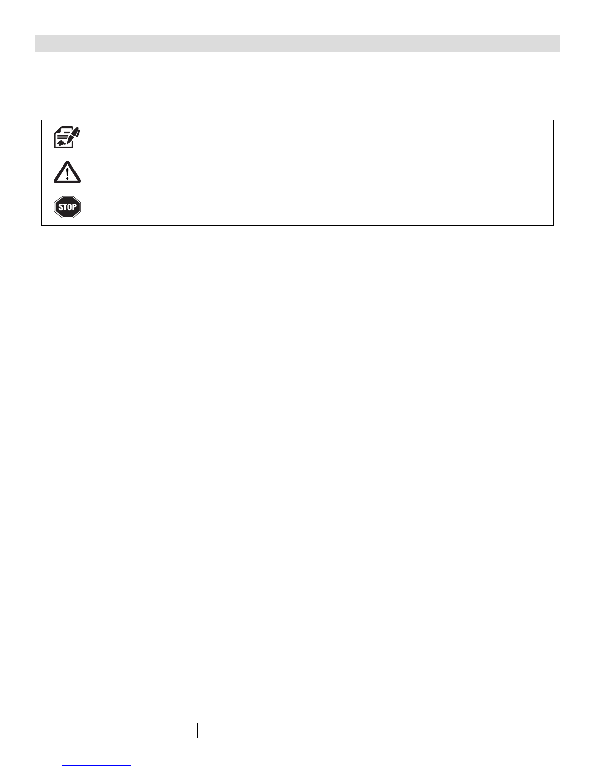
Notes emphasize information and/or provide additional information to assist the user.
Caution messages appear before procedures that could result in damage to equipment if not observed.
Warning messages appear before procedures that could result in personal injury if not observed.
This manual is intended to be used as a basic installation a nd operation g uide for the Welker Pitot Probes, PP-1, PP-2, PP-3, and PP-F. For comp rehensive instructions,
please refer to the IOM Manua ls for each individual component. A list of relevant comp onent IOM Manua ls is provided in Appendix A of this manual.
The informa tion in this manu al has been carefully chec ked for accurac y and is intended to be used a s a guide for the installation, operation, and maintenance o f
the Welker equipment described in this manual. Correct installation and operation, however, are the respo nsibility of the en d user. Welker reserves the right to ma ke
cha nges to this man ual and a ll products in order to improve p erformance and reliability.
BEFOREYOUBEGIN
Read these instructions completely and carefully.
IMPORTANT - Save these instructions for local inspector's use.
IMPORTANT - Observe all governing codes and ordinances.
Note to Installer - Leave these instructions with the end user.
Note to End User - Keep these instructions for future reference.
Installation of this Pitot Probe is of a mechanical nature.
Proper installation is the responsibility of the installer. Product failure due to improper installation is not covered under the warranty.
If you received a damaged Pitot Probe, please contact a Welker representative immediately.
Phone: 281.491.2331
Address: 13839 West Bellfort Street
Sugar Land, TX 77498
IOM-101 MODELS: PP-1, PP-2, PP-3, and PP-F REV: C 13839 West Bellfort St reet, Sugar L and, TX 77498 welker. com Servic e Departm ent 281.491.2331
3
Page 4

SECTION 1: PRODUCTINFORMATION
1.1 Introduction
We appreciate your business and your choice of Welker products. The installation, operation, and maintenance liability for this
equipment becomes that of the purchaser at the time of receipt. Reading the applicable Installation, Operation, and
Maintenance (IOM) Manuals prior to installation and operation of this equipment is required for a full understanding of its
application and performance prior to use.*
If you have any questions, please call Welker at 1-281-491-2331.
*The following p roced ures have been written for use with standard Welker pa rts and eq uipment. Assemblies that have been modified may have additional
requirements and specifications that are not listed in this manual.
1.2 Product Description
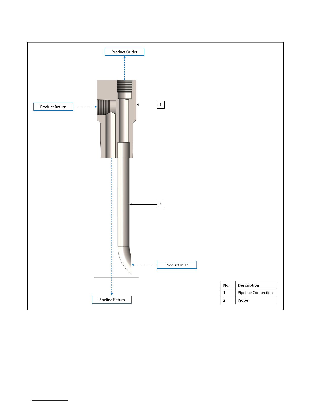
The Welker PP-1, PP-2, PP-3, and PP-F Pitot Probes are designed to create a product loop through a connected sampler or
sampling system.
When the product outlet and return of the unit are connected to a sampler or sampling system, the circulation pump and/or
kinetic energy from flow velocity create a circulation loop, a.k.a. hot loop. When in operation, product circulates through the hot
loop, continually presenting fresh product to the sampler or sampling system, allowing for collection of representative samples.
Welker may custom design the PP-1, PP-2, PP-3, and PP-F to suit the particular application and specifications of each customer.
IOM-101 MODELS: PP-1, PP-2, PP-3, and PP-F REV: C 13839 West Bellfort St reet, Sugar L and, TX 77498 welker. com Servic e Departm ent 281.491.2331
4
Page 5

1.3 Specifications
The specifications listed in this section are generalized for this equipment. Welker can modify the equipment according to your
company's needs. Please note that the specifications may vary depending on the customization of y our equipment.
Products Sampled
Material of Construction
Maximum Allowable Operating Pressure
Connections
Insertion Diameter
Feature
Options
Table 1: PP-1 Specifications
Gases and Liquids Compatible With the Materials of Construction
316/316LStainless Steel
½" MNPT: 7700 psig @ -50 °F to 300 °F (530 barg @ -45 °C to 148 °C)
¾" MNPT: 7300 psig @ -50 °F to 300 °F (503 barg @ -45 °C to 148 °C)
1" MNPT: 5300 psig @ -50 °F to 300 °F (365 barg @ -45 °C to 148 °C)
Pipeline: ½", ¾", or 1" MNPT
Product Inlet and Return: ¼" FNPT
¼" (Standard)
³⁄₈"
Scooped Tip on Inlet Probe
45° Beveled Inlet Probe
Tungsten Carbide and Sulfinert®-Treated Sample Exposed Parts
CRNCertification
Products Sampled
Material of Construction
Maximum Allowable Operating Pressure
Connections
Insertion Diameter
Features
Options
Products Sampled
Material of Construction
Maximum Allowable Operating Pressure
Connections
Insertion Diameter
Features
Option
Table 2: PP-2 Specifications
Gases and Liquids Compatible With the Materials of Construction
316/316LStainless Steel
3600 psig @ -20 °F to 120 °F (248 barg @ -28 °C to 48 °C)
Pipeline: ½", ¾", or 1" MNPT
Product Inlet and Return: ¼" FNPT
¼" (Standard)
³⁄₈"
Ball Valves
Scooped Tip on Inlet Probe
45° Beveled Inlet Probe
Sulfinert®-Treated Sample Exposed Parts
Tungsten Carbide and Sulfinert®-Treated Sample Exposed Parts
CRNCertification
NACECompliance
Table 3: PP-3 Specifications
Gases and Liquids Compatible With the Materials of Construction
316/316LStainless Steel
3600 psig @ -20 °F to 120 °F (248 barg @ -28 °C to 48 °C)
Pipeline: ¾" MNPT (Others Available)
Product Inlet and Return: ¼" FNPT
³⁄₈"
Needle Valves
Scooped Tip on Inlet Probe
45° Beveled Inlet Probe
IOM-101 MODELS: PP-1, PP-2, PP-3, and PP-F REV: C 13839 West Bellfort St reet, Sugar L and, TX 77498 welker. com Servic e Departm ent 281.491.2331
5
Page 6

Products Sampled
Material of Construction
Maximum Allowable
Operating Pressure
Pipeline Connection
Outlet and Return Connections
Tubing Diameter
Features
Options
Table 4: PP-F Specifications
Gases and Liquids Compatible With the Materials of Construction
316/316LStainless Steel (Standard)
Carbon Steel
150 ANSICarbon Steel: 285 psig @ -20 °F to 100 °F (19 barg @ -28 °C to 37 °C)
150 ANSIStainless Steel: 275 psig @ -20 °F to 100 °F (18 barg @ -28 °C to 37 °C)
600 ANSICarbon Steel: 1480 psig @ -20 °F to 100 °F (102 barg @ -28 °C to 37 °C)
600 ANSIStainless Steel: 1440 psig @ -20 °F to 100 °F (99 barg @ -28 °C to 37 °C)
900 ANSICarbon Steel: 2200 psig @ -20 °F to 100 °F (151 barg @ -28 °C to 37 °C)
900 ANSIStainless Steel: 2160 psig @ -20 °F to 100 °F (148 barg @ -28 °C to 37 °C)
1500 ANSI Carbon Steel: 3705 psig @ -20 °F to 100 °F (255 barg @ -28 °C to 37 °C)
1500 ANSI Stainless Steel: 3600 psig @ -20 °F to 100 °F (248 barg @ -28 °C to 37 °C)
Size: 1", 2", or 3"
Rating: 150, 600, 900, or 1500 ANSI
Facing: RF or RTJ
Others Available
¼" FNPT
½" FNPT
³⁄₈" (Standard)
½"
Scooped Tip on Inlet Probe
Shroud
Inlet and Return Ball Valves
NACECompliance
IOM-101 MODELS: PP-1, PP-2, PP-3, and PP-F REV: C 13839 West Bellfort St reet, Sugar L and, TX 77498 welker. com Servic e Departm ent 281.491.2331
6
Page 7
1.4 Equipment Diagrams
Figure 1: PP-1 Diagram
IOM-101 MODELS: PP-1, PP-2, PP-3, and PP-F REV: C 13839 West Bellfort St reet, Sugar L and, TX 77498 welker. com Servic e Departm ent 281.491.2331
7
Page 8
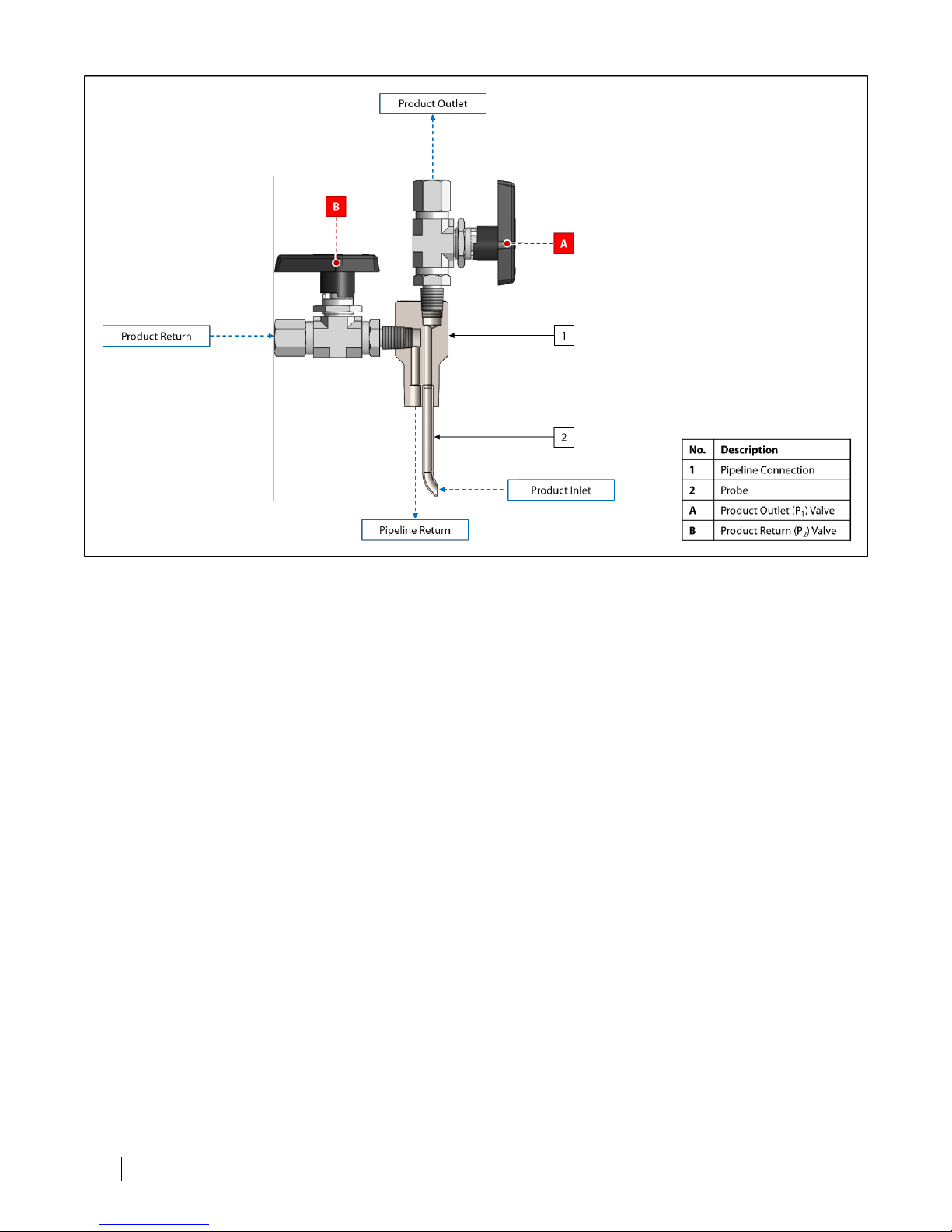
Figure 2: PP-2 Diagram
IOM-101 MODELS: PP-1, PP-2, PP-3, and PP-F REV: C 13839 West Bellfort St reet, Sugar L and, TX 77498 welker. com Servic e Departm ent 281.491.2331
8
Page 9
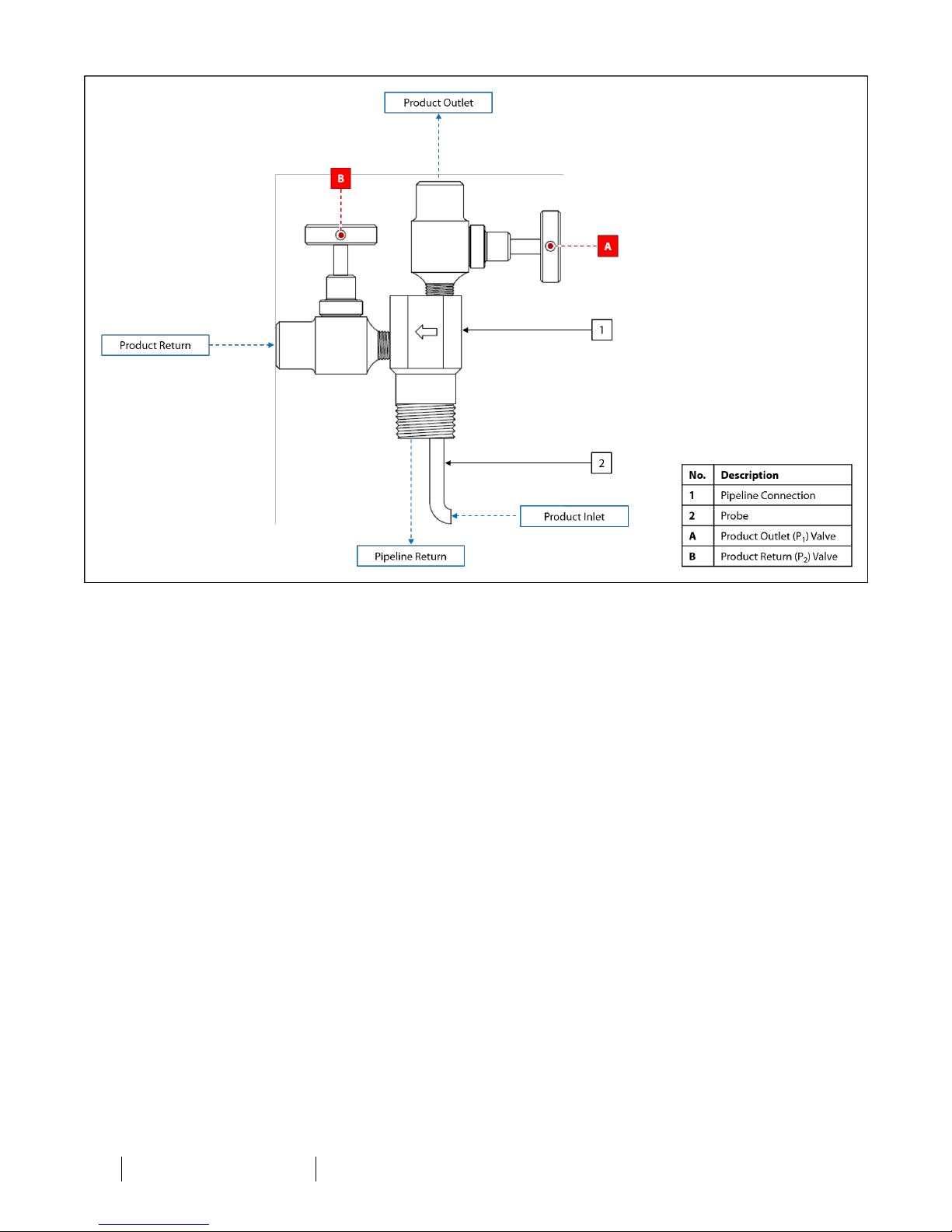
Figure 3: PP-3 Diagram
IOM-101 MODELS: PP-1, PP-2, PP-3, and PP-F REV: C 13839 West Bellfort St reet, Sugar L and, TX 77498 welker. com Servic e Departm ent 281.491.2331
9
Page 10
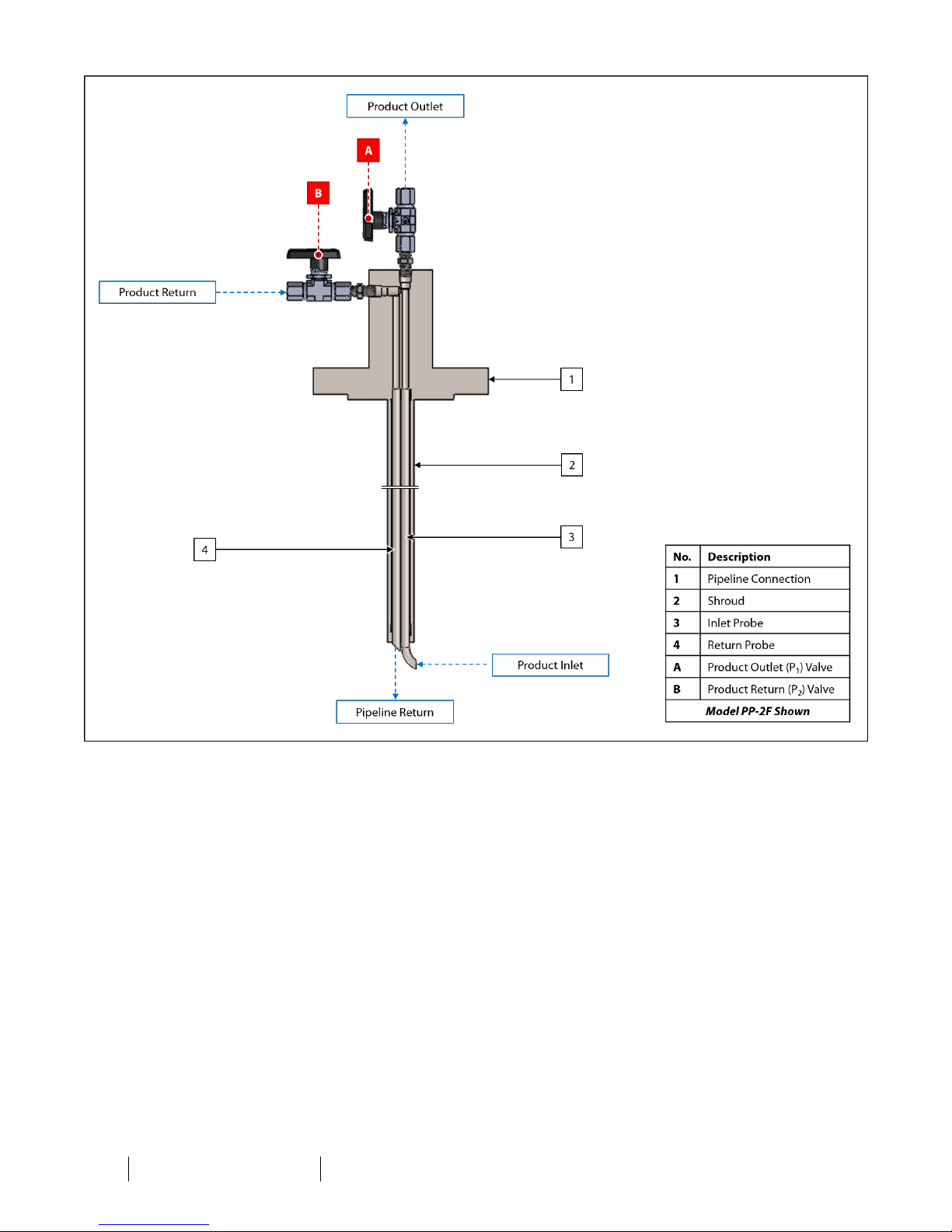
Figure 4: PP-F Diagram
IOM-101 MODELS: PP-1, PP-2, PP-3, and PP-F REV: C 13839 West Bellfort St reet, Sugar L and, TX 77498 welker. com Ser vice Depart ment 281.491.2331
10
Page 11
SECTION 2: INSTALLATION&OPERATION
2.1 Before You Begin
After unpacking the unit, check the equipment for compliance and any damage that may have occurred during shipment.
Immediately contact a Welker representative if you received damaged equipment.
When sealing fittings with PTFE tape, refer to the proper sealing instructions for the brand used.
1. For sampling applications, Welker recommends that the unit be inserted into the center one-third (¹⁄₃) of the pipeline in
a location where the product is well-mixed and will yield an accurate and representative sample.
2. For gas sampling applications, Welker recommends that the unit be installed in the top of the pipe.
3. For liquid sampling applications, Welker recommends that the unit be installed in the side of the pipe.
4. For liquid sampling applications, locate the unit two to four pipe diameters (2–4D) downstream of an inline static mixer
or other flow conditioning system.
5. Handle the unit with care.
2.2 Installation and Operation
1. Depressurize the pipeline.
The pipeline must be depressurized prior to installing and removing the unit.
2.
As necessary, install valves to the pipeline connection (Figure 1). One will be product outlet (P₁) valve A, and the other
will be product return (P₂) valve B.
3.
Ensure that product outlet (P₁) valve A and product return (P₂) valve B are closed (Figure 2, Figure 3, or Figure 4). As
necessary, cut off excess tubing from the probe. Using tubing cutters, remove the excess tubing, and then file and
smooth the cut edge of the probe.
4. If the probe tip is scooped or beveled, determine the direction of product flow in the pipeline. For the Pitot Probe to
function correctly, it must be installed so that the scooped probe tip is open against the direction of product flow.
If applicable, refer to the flow direction stamped on the pipeline connection or handle to determine correct orientation before
installing the Pitot Probe to the pipeline.
5. If the Pitot Probe has an MNPT pipeline connection, continue to step 6. If the Pitot Probe has a flanged pipeline
connection, proceed to step 9.
IOM-101 MODELS: PP-1, PP-2, PP-3, and PP-F REV: C 13839 West Bellfort S treet, Sugar Land , TX 77498 welker .com Ser vice Depar tment 281.491.2331
11
Page 12

MNPTPipeline Connection
6. Wrap the threads of the threaded pipeline connection with PTFEtape.
7. Install the Pitot Probe to the mating connection on the pipeline and tighten.
8. Proceed to step 14.
Flanged Pipeline Connection
9. Position an appropriately sized gasket on the mating flange connection.
10. Install the Pitot Probe to the mating flange connection.
11. Following a cross-bolting sequence, install bolts and nuts to the flanges.
12. Tighten all bolts to the appropriate torque.
13. Continue to step 14.
Completing Installation
14. Pressurize the pipeline and check for leaks.
15.
Use appropriately sized tubing to connect from product outlet (P₁) valve A to the customer equipment (Figure 2, Figure
3, or Figure 4).
16.
Use appropriately sized tubing to connect from the customer equipment to product return (P₂) valve B (Figure 2, Figure
3, or Figure 4).
17.
Open product outlet (P₁) valve A and product return (P₂) valve B to begin operation (Figure 2, Figure 3, or Figure 4).
2.3 Removing the Pitot Probe
1. Depressurize the pipeline.
The pipeline must be depressurized prior to installing and removing the unit.
2.
Close product outlet (P₁) valve A and product return (P₂) valve B (Figure 2, Figure 3, or Figure 4).
3. Disconnect customer equipment from the outlet and return.
4. Remove the Pitot Probe from the pipeline.
IOM-101 MODELS: PP-1, PP-2, PP-3, and PP-F REV: C 13839 West Bellfort S treet, Sugar Land , TX 77498 welker .com Ser vice Depar tment 281.491.2331
12
Page 13
3.1 Before You Begin
SECTION 3: MAINTENANCE
1.
Maintenance is necessary if a leak occurs at one or both valves.
2. Prior to maintenance or disassembly of the unit, it is advisable to have a repair kit available for repairs of the system in
case of unexpected wear or faulty seals.
New seals supplied in spare parts kits should be lightly lubricated before being installed to ease the installation of the seals and
reduce the risk of damage when positioning them on parts. Wipe excess lubricant from the seals, as it may adversely affect
analytical instrument results.
For sample-exposed seals, Welker recommends non-hydrocarbon-based lubricants, such as Krytox®.
For non-sample-exposed seals, Welker recommends either non-hydrocarbon-based lubricants or silicone-based lubricants, such
as Molykote® 111.
After the seals are installed, the outer diameter of shafts and inner diameter of cylinders may be lubricated to allow smooth
transition of parts.
3. All maintenance and cleaning of the unit should be performed on a smooth, clean surface.
4. Welker recommends having adjustable wrenches available for maintenance. Please note that the exact tool required
may vary by model.
IOM-101 MODELS: PP-1, PP-2, PP-3, and PP-F REV: C 13839 West Bellfort S treet, Sugar Land , TX 77498 welker .com Ser vice Depar tment 281.491.2331
13
Page 14

3.2 Maintenance
Maintenance is needed when a leak occurs at product outlet (P₁) valve A and/or product return (P₂) valve B.
1.
Prior to performing maintenance, the Pitot Probe must be removed from the pipeline. See Section 2.3, Removing the
Pitot Probe, for instructions on removing the Pitot Probe from the pipeline.
2.
Unscrew product outlet (P₁) valve A and/or product return (P₂) valve B from the pipeline connection (Figure 2, Figure 3,
or Figure 4).
3.
To perform maintenance on product outlet (P₁) valve A and/or product return (P₂) valve B, refer to the Installation,
Operation, and Maintenance (IOM) Manual for the valve(s).
4. As necessary, clean the probe.
5.
Install product outlet (P₁) valve A and/or product return (P₂) valve B to the pipeline connection (Figure 2, Figure 3, or
Figure 4).
6.
Maintenance is now complete. Reinstall the Pitot Probe according to the instructions in Section 2.2, Installation and
Operation.
Check valves for leaks and repair as necessary during reinstallation.
3.3 Troubleshooting
Issues Possible Causes Solutions
Product outlet (P₁) valve A and/or
product return (P₂) valve B is
leaking.
Table 5: Pitot Probe Troubleshooting
There is debris in the valve.
The valve O-rings and/or seat are worn or
damaged.
Maintain the valve. Refer to the
Installation, Operation, and Maintenance
(IOM) Manual for the valve for
maintenance instructions.
Maintain the valve. Refer to the
Installation, Operation, and Maintenance
(IOM) Manual for the valve for
maintenance instructions.
IOM-101 MODELS: PP-1, PP-2, PP-3, and PP-F REV: C 13839 West Bellfort S treet, Sugar Land , TX 77498 welker .com Ser vice Depar tment 281.491.2331
14
Page 15

APPENDIX A: REFERENCEDORATTACHEDDOCUMENTS
Welker Installation, Operation, and Maintenance (IOM) Manuals suggested for use with this unit:
l IOM-105: Welker NV-1 and NV-2 Instrument Valves
Other Installation, Operation, and Maintenance (IOM) Manuals suggested for use with this unit:
l Apollo Valves 76-100 Series Stainless Steel Ball Valve With Mounting Pad 1⁄4" - 1" (Welker IOM-V141)
l Parker Hannifin Corporation BallValves B Series (Welker IOM-V365)
l Parker Hannifin Corporation Ball and Plug Valves (Welker IOM-V213)
Welker drawings and schematics suggested for use with this unit:
l Assembly Drawing: AD626BA (PP-2)
l Assembly Drawing: AD626BJ (PP-3)
l Assembly Drawing: AD843BD.1 (PP-F)
l Machine Drawing:PP1231 (PP-1)
IOM-101 MODELS: PP-1, PP-2, PP-3, and PP-F REV: C 13839 West Bellfort S treet, Sugar Land , TX 77498 welker .com Ser vice Depar tment 281.491.2331
15
Page 16

NOTES
____________________________________________________________________________________________________
____________________________________________________________________________________________________
____________________________________________________________________________________________________
____________________________________________________________________________________________________
____________________________________________________________________________________________________
____________________________________________________________________________________________________
____________________________________________________________________________________________________
____________________________________________________________________________________________________
____________________________________________________________________________________________________
____________________________________________________________________________________________________
____________________________________________________________________________________________________
____________________________________________________________________________________________________
____________________________________________________________________________________________________
____________________________________________________________________________________________________
____________________________________________________________________________________________________
____________________________________________________________________________________________________
____________________________________________________________________________________________________
____________________________________________________________________________________________________
____________________________________________________________________________________________________
13839 West Bellfort Street
Sugar Land, TX77498
Phone: 281.491.2331
IOM-101 MODELS: PP-1, PP-2, PP-3, and PP-F REV: C 13839 West Bellfort S treet, Sugar Land , TX 77498 welker .com Ser vice Depar tment 281.491.2331
16
welker.com
 Loading...