

Page 1

INSTALLATION, OPERATION, ANDMAINTENANCEMANUAL
WELKER CONSTANTPRESSURESAMPLECONTAINER
MODEL
LS-14
DRAWING NUMBERS
AD245.HCRN
AD245CRN
AD245CV
MANUALNUMBER
IOM-131
REVISION
Rev. F, 9/11/2019
Page 2

TABLEOF CONTENTS
SAFETY 3
1. PRODUCT INFORMATION 4
1.1 Introduction 4
1.2 Product Description 4
1.3 Specifications 5
1.4 Equipment Diagrams 7
2. INSTALLATION & OPERATION 14
2.1 Before You Begin 14
2.2 Installation 14
2.3 Preparing forSampling 19
2.4 Composite Sampling 20
3. MAINTENANCE 22
3.1 Before You Begin 22
3.2 Maintenance 22
3.3 Troubleshooting 30
APPENDIX 32
A: Referenced or Attached Documents 32
Copyright © 2019 Welker,Inc. All rights reserved. Welker®, W Welker®, Wlogo, WelkerScope®, Welker Jet®, andOdorEyes®areregistered trademarks of Welker,Inc.
IOM-131 MODEL: LS -14 REV: F 13839 West Bellfort St reet, Sugar L and, TX 77498 welker. com Servic e Departm ent 281.491.2331
2
Page 3
SAFETY
IMPORTANTSAFETYINFORMATION
READALLINSTRUCTIONS
Notes emphasize information and/or provide additional information to assist the user.
Caution messages appear before procedures that could result in damage to equipment if not observed.
Warning messages appear before procedures that could result in personal injury if not observed.
This manual is intended to be used as a basic installation a nd operation g uide for the Welker Constant Pressure Sam ple Container, LS-14. For comprehen sive
instructions, please refer to the IOM Manuals for each ind ividu al componen t. A list of relevant component IOM Manu als is p rovided in Appendix A of this manual.
The informa tion in this manu al has been carefully chec ked for accurac y and is intended to be used a s a guide for the installation, operation, and maintenance o f
the Welker equipment described in this manual. Correct installation and operation, however, are the respo nsibility of the en d user. Welker reserves the right to ma ke
cha nges to this man ual and a ll prod ucts in order to improve performan ce and relia bility.
BEFOREYOUBEGIN
Read these instructions completely and carefully.
IMPORTANT - Save these instructions for local inspector's use.
IMPORTANT - Observe all governing codes and ordinances.
Note to Installer - Leave these instructions with the end user.
Note to End User - Keep these instructions for future reference.
Installation of this Constant Pressure Sample Container is of a mechanical and electrical nature.
Proper installation is the responsibility of the installer. Product failure due to improper installation is not covered under the warranty.
If you received a damaged Constant Pressure Sample Container, please contact a Welker representative immediately.
Phone: 281.491.2331
Address: 13839 West Bellfort Street
Sugar Land, TX 77498
IOM-131 MODEL: LS -14 REV: F 13839 West Bellfort St reet, Sugar L and, TX 77498 welker. com Servic e Departm ent 281.491.2331
3
Page 4

SECTION 1: PRODUCTINFORMATION
1.1 Introduction
We appreciate your business and your choice of Welker products. The installation, operation, and maintenance liability for this
equipment becomes that of the purchaser at the time of receipt. Reading the applicable Installation, Operation, and
Maintenance (IOM) Manuals prior to installation and operation of this equipment is required for a full understanding of its
application and performance prior to use.*
If you have any questions, please call Welker at 1-281-491-2331.
*The following p ro cedures have been written for use with stand ard Welker parts and equipm ent. Assemblies that have been modified may have additional
requirements and specifications that are not listed in this manual.
1.2 Product Description
The Welker LS-14 Constant Pressure Sample Container is designed to collect, retain, and mix large volumes of representative
composite sample.
The LS-14 can be integrated into a system with a pneumatically driven sample pump that interfaces with a Programmable Logic
Controller (PLC) or other signal control system for proportional to flow or timed collection of sample grabs. Product level can be
visually verified on site by referring to the volume indicator with tracker magnet on the LS-14.
Engineered features ensure that the sample is retained and representative for laboratory analysis. The connected inert gas supply
applies and maintains constant pressure on the sample in the LS-14 to prevent vaporization and the escape of entrained gases.
An operator can manually actuate the mixing plate in the LS-14 to thoroughly mix the sample prior to transfer to a transportable
container for laboratory analysis.
Optional equipment can be added to enable remote operation: a controller to take samples automatically, an electro-hyrdaulic
supply to drive the incorporated sample pump, a magnetostrictive level indicator to communicate product level to the PLC, and
a proximity switch to signal the PLC once the desired volume of sample has been collected.
For this manual, the term "PLC," or Programmable Logic Controller, will be used to refer to the PLC, DCS, or other signal control
system used by the customer to activate and operate the solenoid.
Welker may custom design the LS-14 to suit the particular application and specifications of each customer.
IOM-131 MODEL: LS -14 REV: F 13839 West Bellfort St reet, Sugar L and, TX 77498 welker. com Servic e Departm ent 281.491.2331
4
Page 5

1.3 Specifications
The specifications listed in this section are generalized for this equipment. Welker can modify the equipment according to your
company's needs. Please note that the specifications may vary depending on the customization of your equipment.
Products Sampled
Materials of Construction
Maximum Allowable
Operating Pressure
Connections
Utility Requirements
Electrical Connections
Volume
Operation
Dimensions
Features
Table 1: LS-14 Specifications
Condensate, Light Crude Oil, Light Liquid Hydrocarbons, Liquid Petroleum Gas,
Natural Gas Liquids, and Refined Products
316/316LStainless Steel, Aluminum, Carbon Steel, PTFE, and Viton®
Others Available
2160 psig @ -20 °F to 100 °F (148 barg @ -28 °C to 37 °C)
Others Available
Composite SampleDraw Off: ¼" FNPT
Inert Gas Supply Fill Inlet: ¼" FNPT
Pneumatic Supply Inlet (Optional): ¼" Tubing
Product Return: ¼" FNPT
Sample Inlet: ¼" FNPT
5 or 10 USGallon Hydraulic Oil Reservoir (Optional)
Inert Gas Supply
Electro-hydraulic Unit (EHUC) (Optional): AC 110 V, AC 220 V, or AC 480 V, ¾" FNPT
Magnetostrictive Level Indicator (Optional): DC 24 V, 4–20 mA Output, ¾" FNPT
Solenoid(s): AC 110 V, AC 240 V, DC 12 V, or DC 24 V
1½ USGallons @ 80%
3 USGallons @ 80%
5 USGallons @ 80%
10 USGallons @ 80%
Hydraulic or Pneumatic Mixer Actuation
12" x 12" Mounting Plate (Standard)
24" x 28" x 2" (Length x Width x Height) Painted Carbon Steel Skid
36" x 22" x 2" (Length x Width x Height) Painted Carbon Steel Skid With Center Post
42" x 30" x 2" (Length x Width x Height) Painted Carbon Steel Skid With Center Post
Composite Sample Draw Off Port/Valve
Inert Gas Supply Tank
Inert Gas Supply Tank Port/Valve
Manifold Block
Mixer Actuation Solenoid
Plate Mixer
Pressure Gauges
Product Return Port/Valve
Sample Inlet Port / CheckValve
Skid WeldAssembly
VisualMagnetic Volume Indicator
IOM-131 MODEL: LS -14 REV: F 13839 West Bellfort St reet, Sugar L and, TX 77498 welker. com Servic e Departm ent 281.491.2331
5
Page 6

Options
Table 1: LS-14 Specifications (Continued)
Digital Controller
Electro-hydraulic Unit
Flow Switch
Magnetostrictive LevelIndicator
Pneumatic Supply Conditioning System
Proximity Switch
Solenoid(s)
Welker AVA-2 Volume Analyzer
Welker inLoop™ Crude OilSampler
Welker MPS-2 Gas Sampler
Welker SSO-9M Mini Injection Pump
Welker SSO-9MEDInjection Pump
CRNCertification
IOM-131 MODEL: LS -14 REV: F 13839 West Bellfort St reet, Sugar L and, TX 77498 welker. com Servic e Departm ent 281.491.2331
6
Page 7
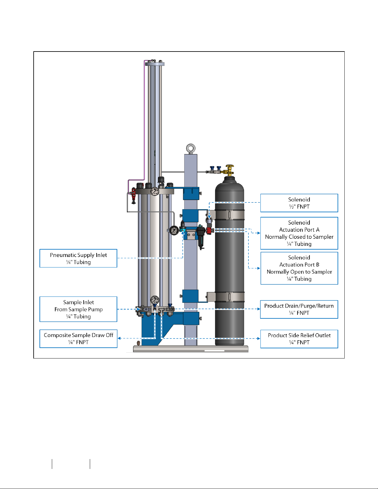
1.4 Equipment Diagrams
Figure 1: Standard LS-14 Connections Diagram
IOM-131 MODEL: LS -14 REV: F 13839 West Bellfort St reet, Sugar L and, TX 77498 welker. com Servic e Departm ent 281.491.2331
7
Page 8
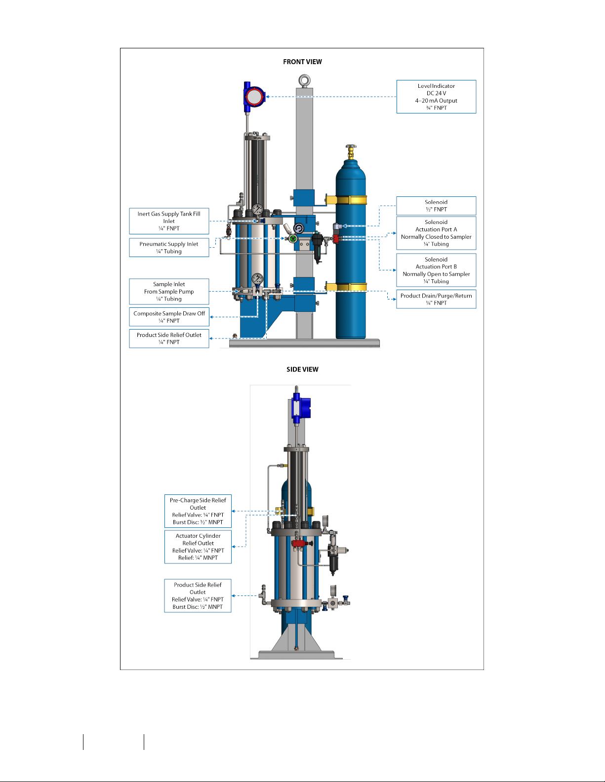
Figure 2: CRN-Certified LS-14 Connections Diagram
IOM-131 MODEL: LS -14 REV: F 13839 West Bellfort St reet, Sugar L and, TX 77498 welker. com Servic e Departm ent 281.491.2331
8
Page 9
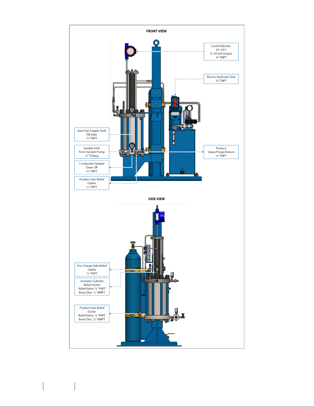
Figure 3: CRN-Certified LS-14 WithOptional Hydraulic Mixer Actuation Connections Diagram
IOM-131 MODEL: LS -14 REV: F 13839 West Bellfort St reet, Sugar L and, TX 77498 welker. com Servic e Departm ent 281.491.2331
9
Page 10
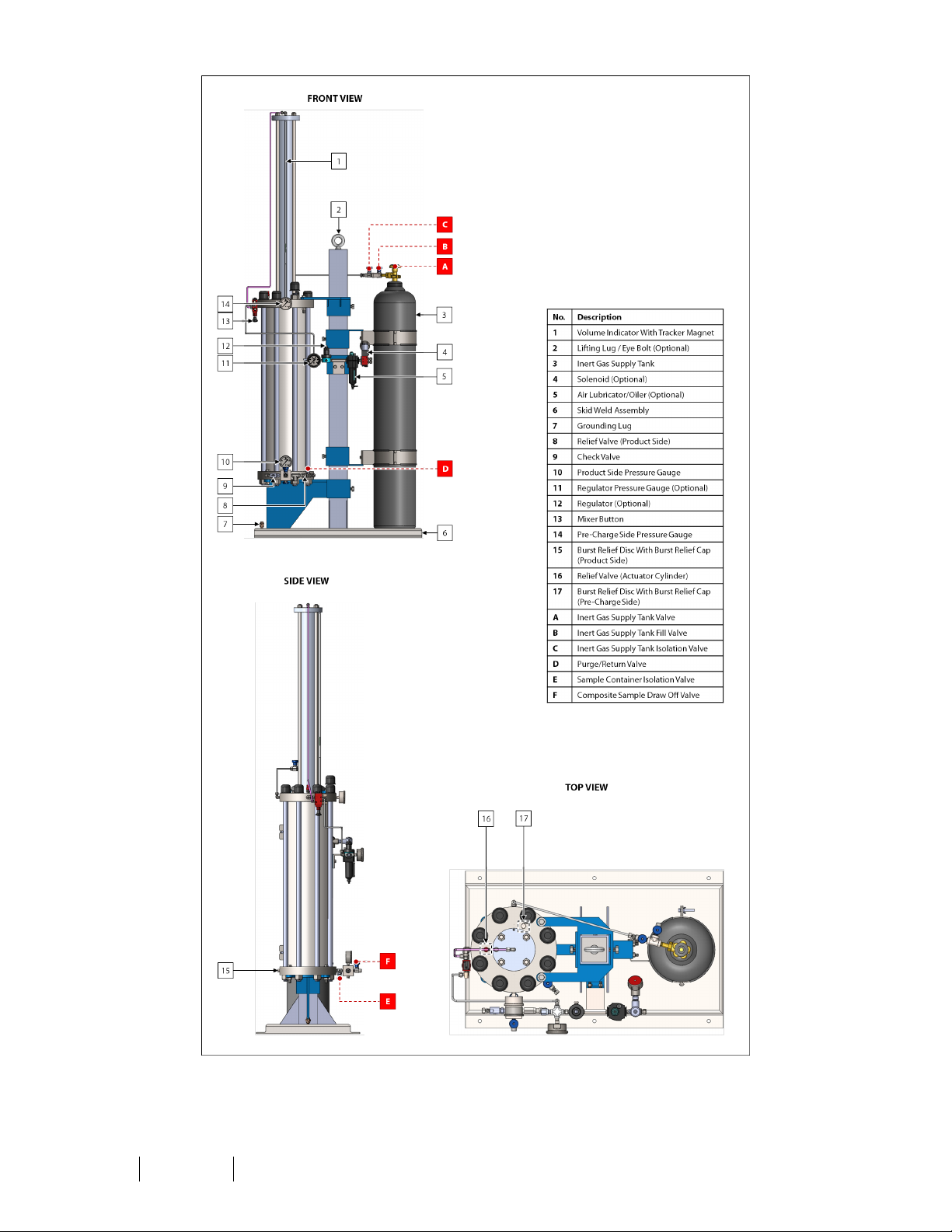
Figure 4: Standard LS-14 Diagram
IOM-131 MODEL: L S-14 REV: F 13839 West Bellfort St reet, Sugar L and, TX 77498 welker. com Servic e Departm ent 281.491.2331
10
Page 11
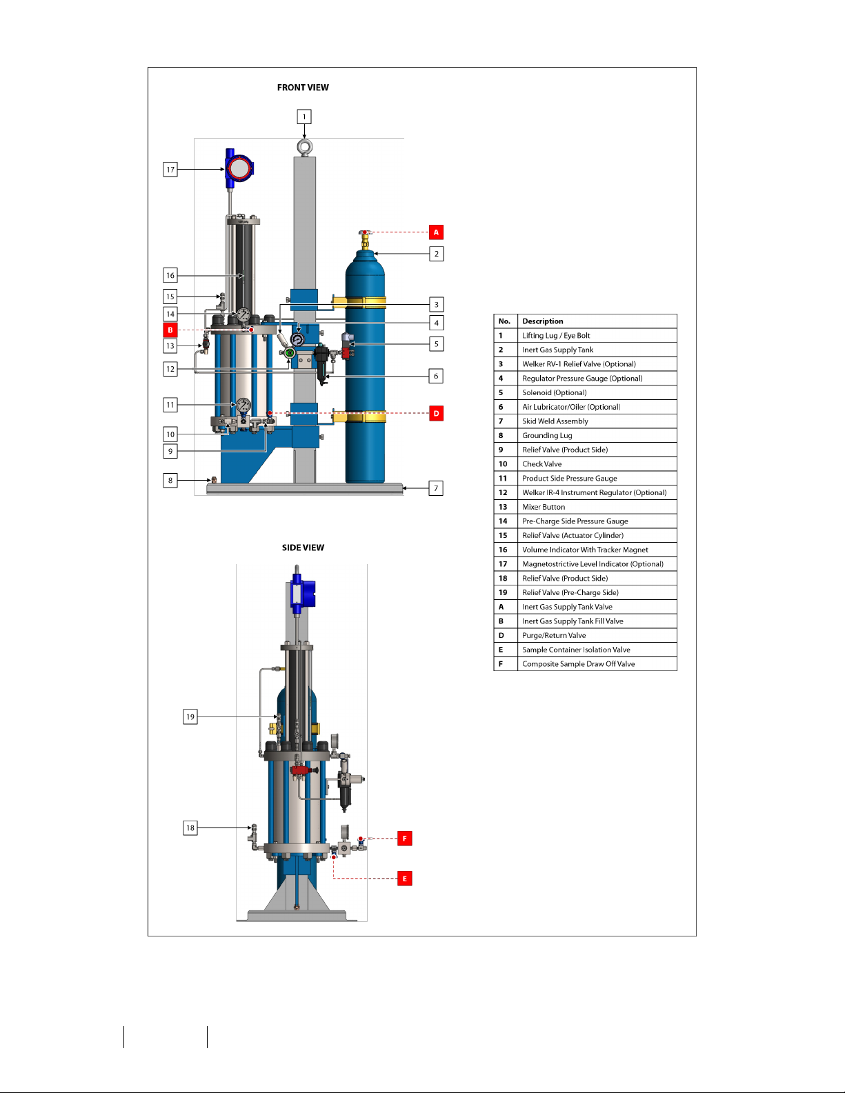
Figure 5: CRN-Certified LS-14 Diagram
IOM-131 MODEL: L S-14 REV: F 13839 West Bellfort St reet, Sugar L and, TX 77498 welker. com Servic e Departm ent 281.491.2331
11
Page 12
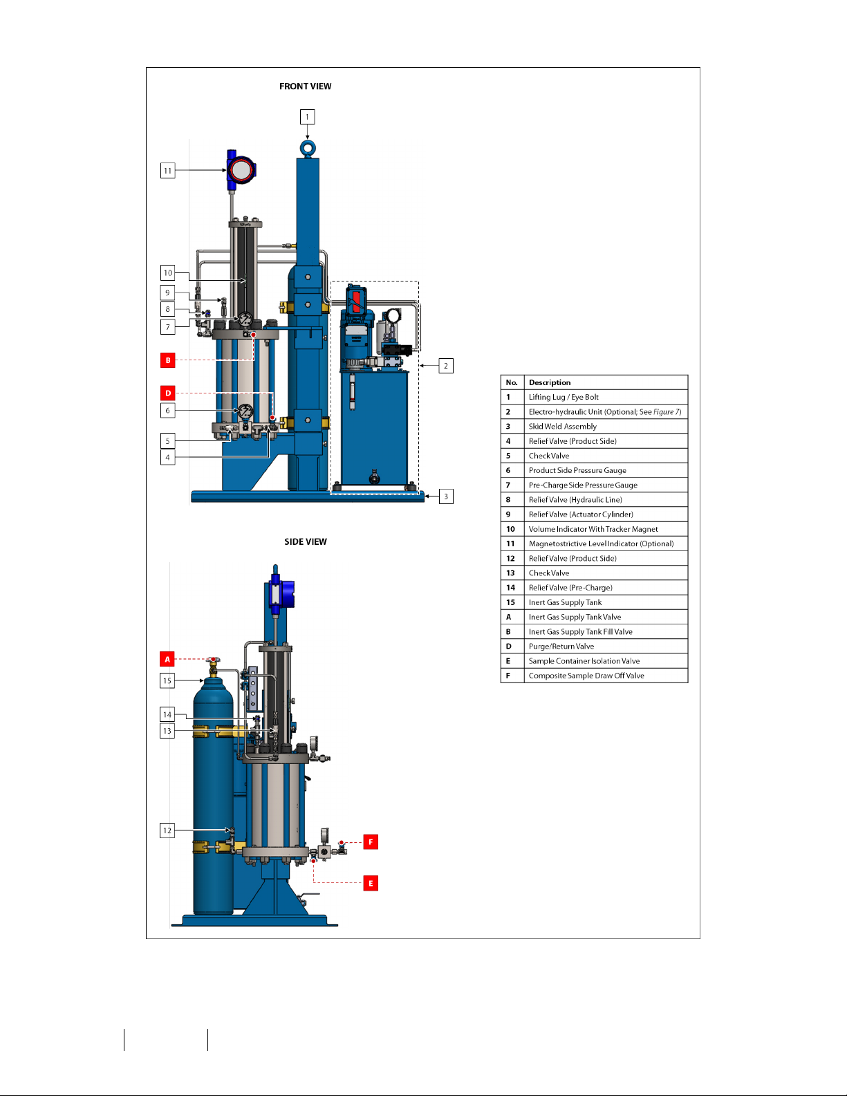
Figure 6: CRN-Certified LS-14 With Optional Hydraulic Mixer Actuation Diagram
IOM-131 MODEL: L S-14 REV: F 13839 West Bellfort St reet, Sugar L and, TX 77498 welker. com Servic e Departm ent 281.491.2331
12
Page 13
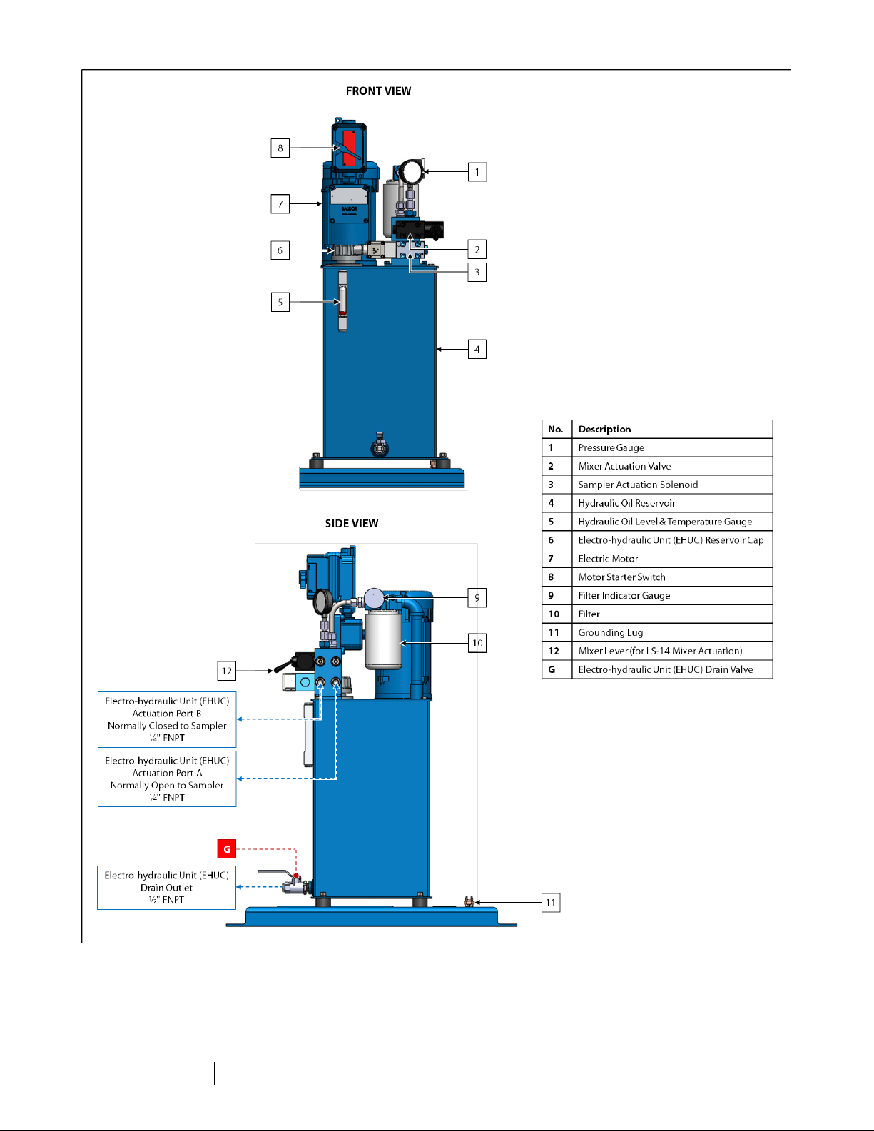
Figure 7: Electro-hydraulic Unit (EHUC) Diagram (Optional)
IOM-131 MODEL: L S-14 REV: F 13839 West Bellfort St reet, Sugar L and, TX 77498 welker. com Servic e Departm ent 281.491.2331
13
Page 14
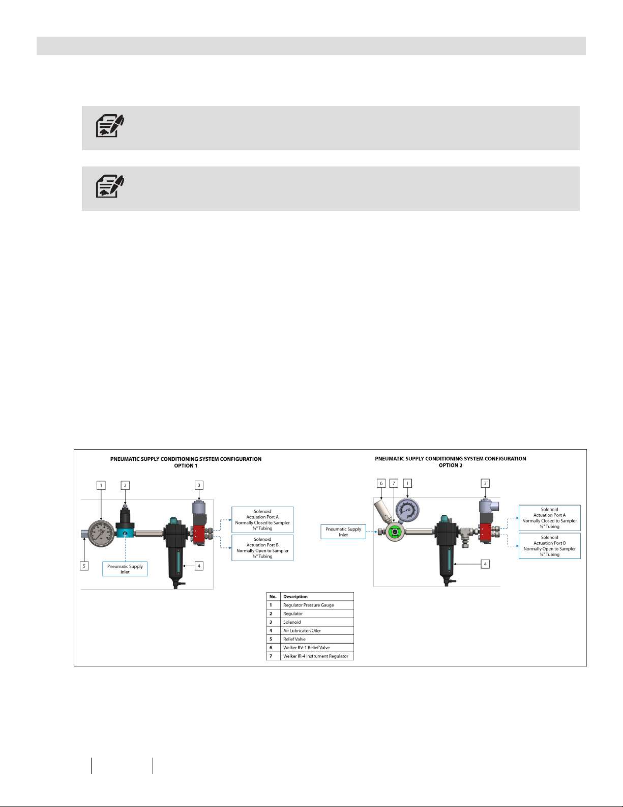
2.1 Before You Begin
2.2 Installation
SECTION 2: INSTALLATION&OPERATION
After unpacking the unit, check the equipment for compliance and any damage that may have occurred during shipment.
Immediately contact a Welker representative if you received damaged equipment.
When sealing fittings with PTFE tape, refer to the proper sealing instructions for the brand used.
1.
2.
3.
4.
5.
6.
7.
8.
Locate the skid as close as possible to the sample point.
Mount the skid to a flat, level surface, such as a concrete slab.
Connect a grounding wire to the grounding lug on the skid to safely ground the system (Figure 4, Figure 5, or Figure 7).
Ensure that all valves on the LS-14 are closed (Figure 4, Figure 5, or Figure 6).
Using appropriately sized tubing, connect from purge/return valve D to the pipeline (Figure 4, Figure 5, or Figure 6).
As necessary, connect a sampler to the sample inlet on the manifold block (Figure 1, Figure 2, or Figure 3).
As necessary, connect from the solenoid to the sampler (Figure 1, Figure 2, or Figure 7).
Apply pressure from the sampler to the manifold block. Check for leaks and repair as necessary.
9. As necessary, fill the reservoir of the air lubricator/oiler to the maximum fill line with oil compatible with the seal
material (Figure 8). Refer to the Installation, Operation, and Maintenance (IOM) Manual for the air lubricator/oiler for
instructions on filling the reservoir and for recommendations on the type of oil to use.
Figure 8: Pneumatic Supply Conditioning System
10.
11.
As necessary, connect a clean, dry pneumatic supply to the pneumatic supply inlet on the regulator (Figure 8).
As necessary, open the reservoir cap on the EHUC, and then fill the EHUC with the appropriate volume of ISO 46
hydraulic oil (Figure 7).
IOM-131 MODEL: L S-14 REV: F 13839 West Bellfort St reet, Sugar L and, TX 77498 welker. com Servic e Departm ent 281.491.2331
14
Page 15
12.
13.
14.
As necessary, connect an appropriate electrical supply to the EHUC (Figure 3).
As necessary, connect a DC 24 V electrical supply to the level indicator (Figure 2 or Figure 3).
As necessary, connect the solenoid to the PLC. Refer to industry standards for appropriate electrical connections to
interface with the PLC.
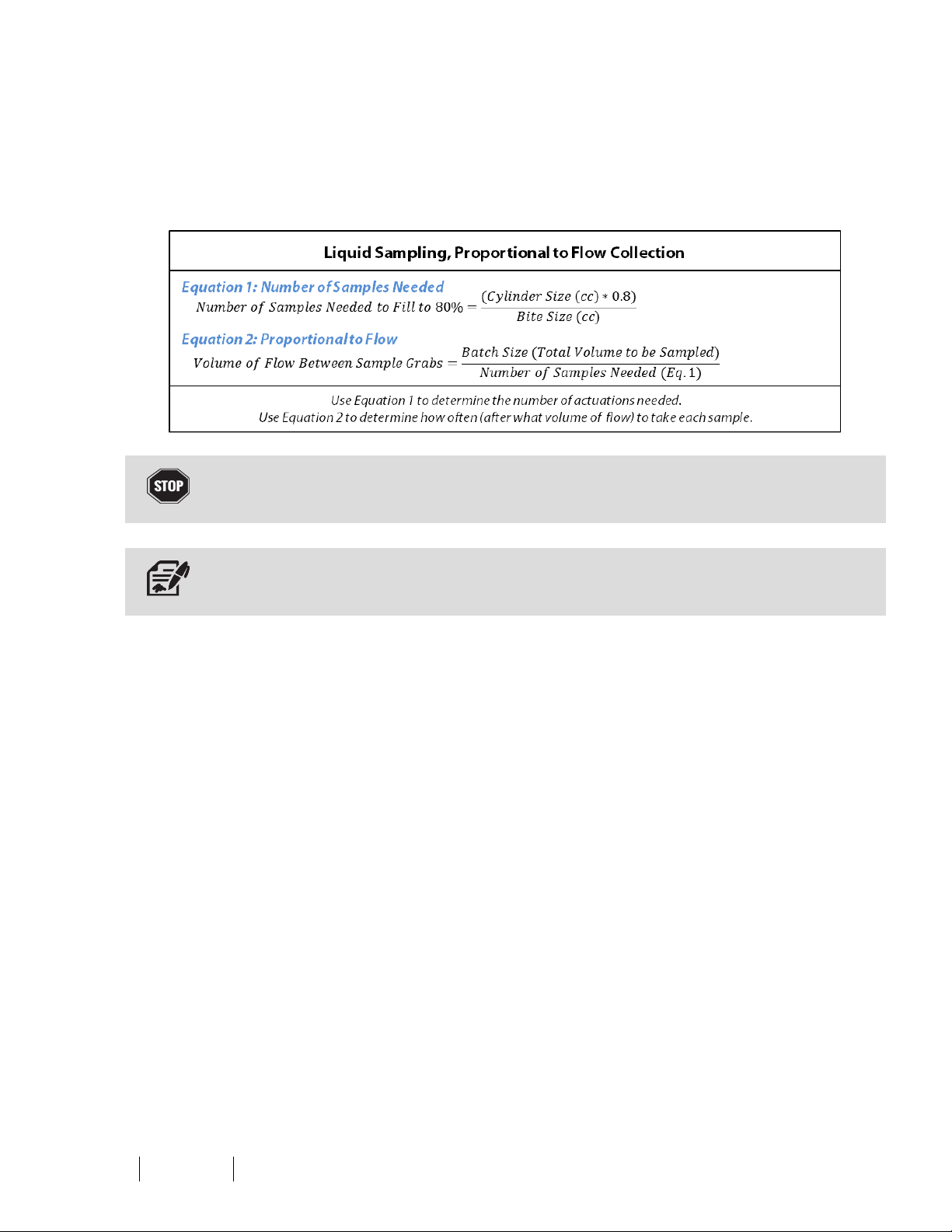
15. As necessary, set the PLC to the desired proportional to flow sampling frequency based on the sampling actuation
equations provided (Figure 9).
Figure 9: Sampling Frequency Equations
Never fill the cylinder above 80% of its capacity. Allow at least 20% room for product expansion should the cylinder be exposed
to increased temperatures.
Note that there are 3,785 cc in 1 US gallon. The LS-14 may be 1½, 3, 5, or 10 USgallons at 80%.
IOM-131 MODEL: L S-14 REV: F 13839 West Bellfort St reet, Sugar L and, TX 77498 welker. com Servic e Departm ent 281.491.2331
15
Page 16
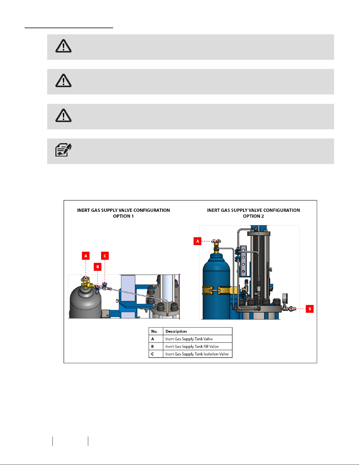
Filling the Inert Gas Supply Tank
The inert gas being used to pre-charge the LS-14 must be compatible with the seals in the LS-14. Welker recommends using
nitrogen or helium as the inert gas supply.
The relief valves and gauges must be adequate for the pressure used to pre-charge the LS-14.
Pre-charging must be complete before product is supplied to the system.
Inert gas tanks are shipped empty from the manufacturer.
16.
Determine the configuration of the inert gas supply valves on the LS-14 (Figure 10). If the LS-14 is equipped with option
1, continue to step 17. If the LS-14 is equipped with option 2, proceed to step 27.
Figure 10: Inert Gas Supply Valve Configuration Options
IOM-131 MODEL: L S-14 REV: F 13839 West Bellfort St reet, Sugar L and, TX 77498 welker. com Servic e Departm ent 281.491.2331
16
Page 17
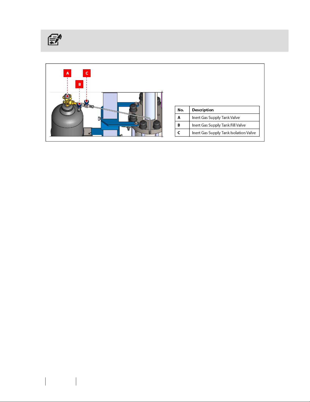
Inert Gas Supply Valve Configuration Option 1
Filling the inert gas supply tank with inert gas supply tank isolation valve C open also pre-charges the LS-14.
Figure 11: Inert Gas Supply Valve Configuration Option 1
17.
18.
19.
20.
21.
22.
23.
24.
25.
26.
Connect an appropriate customer-supplied nitrogen or other inert gas supply container to inert gas supply tank fill valve
B located between the valve on the inert gas supply tank (valve A) and the isolation valve (valve C) (Figure 11).
Open valves A and C, and then slowly open valve B (Figure 11).
Allow the inert gas supply tank to fill.
While filling the inert gas supply tank, refer to the pre-charge side pressure gauge to monitor the pressure of the tank
(Figure 4).
If the product side pressure gauge shows pressure, open purge/return valve D to lower the piston and relieve pressure
within the LS-14 (Figure 4).
Fill the inert gas supply tank until the pre-charge side pressure gauge reads 50–100 psig above pipeline operating
pressure, not to exceed the maximum allowable operating pressure of the LS-14.
Once full, close valve B and disconnect the customer-supplied inert gas supply container. Valves A andC must remain
open (Figure 11).
Plug the port of valve B by wrapping the threads of a male hex plug withPTFEtape and screwing it into the port of
valve B (Figure 11). Valve B must remain plugged at all times except when adding inert gas to the inert gas supply tank.
Check all connections between the inert gas supply tank and the receiver cylinder for leaks. Repair as necessary.
If the LS-14 will use pneumatics for mixer actuation, proceed to step 37. If the LS-14 will use hydraulics for mixer
actuation, proceed to Section 2.3, Preparing for Sampling.
IOM-131 MODEL: L S-14 REV: F 13839 West Bellfort St reet, Sugar L and, TX 77498 welker. com Servic e Departm ent 281.491.2331
17
Page 18
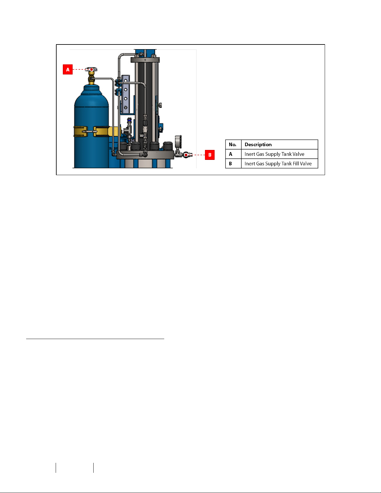
Inert Gas Supply Valve Configuration Option 2
Figure 12: Inert Gas Supply Valve Configuration Option 2
27.
Connect an appropriate customer-supplied nitrogen or other inert gas supply container to inert gas supply tank fill valve
B located in front of the pre-charge pressure gauge (Figure 12).
28.
29.
30.
Open valve A, and then slowly open valve B (Figure 12).
Allow the inert gas supply tank to fill.
While filling the inert gas supply tank, refer to the pre-charge side pressure gauge to monitor the pressure of the tank
(Figure 5 or Figure 6).
31.
If the product side pressure gauge shows pressure, open purge/return valve D to lower the piston and relieve pressure
within the LS-14 (Figure 5 or Figure 6).
32.
Fill the inert gas supply tank until the pre-charge side pressure gauge reads 50–100 psig above pipeline operating
pressure, not to exceed the maximum allowable operating pressure of the LS-14.
33.
Once full, close valve B and disconnect the customer-supplied inert gas supply container. Valve A must remain open
(Figure 12).
34.
Plug the port of valve B by wrapping the threads of a male hex plug withPTFEtape and screwing it into the port of
valve B (Figure 12). Valve B must remain plugged at all times except when adding inert gas to the inert gas supply tank.
35.
36.
Check all connections between the inert gas supply tank and the receiver cylinder for leaks. Repair as necessary.
If the LS-14 will use pneumatics for mixer actuation, continue to step 37. If the LS-14 will use hydraulics for mixer
actuation, proceed to Section 2.3, Preparing for Sampling.
Regulating the Pneumatic Supply (As Necessary)
37.
38.
Turn on the pneumatic supply.
Regulate the pneumatic supply to approximately 40–45 psig.
IOM-131 MODEL: L S-14 REV: F 13839 West Bellfort St reet, Sugar L and, TX 77498 welker. com Servic e Departm ent 281.491.2331
18
Page 19

2.3 Preparing for Sampling
1. Open the pipeline connection.
2.
As necessary, adjust the sample volume on the sampler. Refer to the Installation, Operation, and Maintenance (IOM)
Manual for the sampler for instructions on adjusting the sample volume.
3. TurnONpower to the system.
4.
As necessary, manually turnON the motor starter for the EHUC (Figure 7).
5. Purge the LS-14 prior to beginning composite sampling.
Purging the LS-14
Welker recommends that the LS-14 be evacuated or purged prior to each sample batch to prevent cross-contamination
between samples.
6.
Open sample container isolation valve E (Figure 4, Figure 5, or Figure 6). Ensure that composite sample draw off valve F
is closed.
7. Begin product flow through the system.
8.
Open purge/return valve D (Figure 4, Figure 5, or Figure 6).
9. Manually or remotely actuate the sampler to purge the line of air or previous product.
10.
Once all previous product has drained from the LS-14, close purge/return valve D (Figure 4, Figure 5, or Figure 6).
Verifying Sampler Operation
11.
Close sample container isolation valve E (Figure 4, Figure 5, or Figure 6).
12. Manually actuate the sampler using the manual override on the solenoid.
13.
Observe the product side pressure gauge on the LS-14 (Figure 4, Figure 5, or Figure 6). If the sampler is operating
correctly, a spike in pressure is shown.
14.
Once sampler operation has been verified, open sample container isolation valve E on the manifold block (Figure 4,
Figure 5, or Figure 6).
Valve E on the manifold block must remain open for the duration of composite sampling.
IOM-131 MODEL: L S-14 REV: F 13839 West Bellfort St reet, Sugar L and, TX 77498 welker. com Servic e Departm ent 281.491.2331
19
Page 20
2.4 Composite Sampling
1. If the LS-14 is equipped with inert gas supply valve configuration option 1, ensure that valves A and C on the inert gas
supply tank are open (Figure 11). If the LS-14 is equipped with inert gas supply valve configuration option 2, ensure that
valve A on the inert gas supply tank is open (Figure 12).
Valves A and C on the inert gas supply tank must remain open for the duration of composite sampling.
2.
Ensure that sample container isolation valve E is open (Figure 4, Figure 5, or Figure 6).
If sample container isolation valve E is not open, product will vent through the relief valve instead of entering the LS-14.
3.
4.
5.
6.
As necessary, ensure that the EHUCis ON (Figure 7).
Ensure that the pipeline connection is open and sample is flowing to the sample receiver.
For sampling operation procedures, refer to the Installation, Operation, and Maintenance (IOM) Manual for the sampler.
The magnetic volume indicator on the LS-14 should begin to rise as product fills the LS-14.
7. Allow the LS-14 to fill to the desired volume, not to exceed 80%.
Never fill the cylinder above 80% of its capacity. Allow at least 20% room for product expansion should the cylinder be exposed
to increased temperatures.
Withdrawing Product for Transportation After Composite Sampling
Welker recommends the following transportable containers for use with this unit:
• Welker Constant Pressure Cylinders for light liquid products;
• Welker Constant Pressure Cylinders or chilled containers for Reid vapor pressure (RVP) testing; and
• capped metal or amber glass containers of the appropriate volume for retain samples.
8.
9.
As necessary, turn OFF and isolate the sampler from the LS-14.
To transfer sampled product to a constant pressure cylinder for laboratory analysis, connect the product side of the
constant pressure cylinder to composite sample draw off valve F (Figure 4, Figure 5, or Figure 6). The cylinder should
have a pre-charge pressure of approximately 100 psig above the product pressure in the LS-14. Refer to the Installation,
Operation, and Maintenance (IOM) Manual for the constant pressure cylinder for pre-charging instructions.
10.
Prior to withdrawing sampled product from the LS-14, the operator should manually cycle the mixer four to five times
(4–5x). If the LS-14 is equipped with a pneumatic mixer, alternately press and release the mixer button on the side of
the LS-14 (Figure 4 or Figure 5). If the LS-14 is equipped with a hydraulic mixer, alternately hold up and release the
mixer lever on the EHUC (Figure 7).
11.
With sample container isolation valve E open, open composite sample draw off valve F on the LS-14, and then open the
inlet valve on the constant pressure cylinder (Figure 4, Figure 5, or Figure 6).
12.
Slowly open the product purge valve on the constant pressure cylinder to purge any air. Shut the valve completely once
liquid begins to purge.
13.
Actuate the mixer for another three to four (3–4) complete cycles.
IOM-131 MODEL: L S-14 REV: F 13839 West Bellfort St reet, Sugar L and, TX 77498 welker. com Servic e Departm ent 281.491.2331
20
Page 21
14. Slowly open the pre-charge valve on the constant pressure cylinder and allow the constant pressure cylinder to fill to
the desired volume, not to exceed 80%.
Never fill the cylinder above 80% of its capacity. Allow at least 20% room for product expansion should the cylinder be exposed
to increased temperatures.
15.
After the transfer is complete, close composite sample draw off valve F on the LS-14 and the inlet valve on the constant
pressure cylinder (Figure 4, Figure 5, or Figure 6).
16.
17.
Disconnect the constant pressure cylinder from composite sample draw off valve F (Figure 4, Figure 5, or Figure 6).
Tag the constant pressure cylinder and prepare it for transportation to the testing laboratory in accordance with
company policy.
18.
If desired, repeat steps 9–17 to transfer any sampled product remaining in the LS-14 to additional constant pressure
cylinders for laboratory analysis.
Draining the LS-14
Any sample remaining in the LS-14 must be eliminated prior to the start of the next round of composite sampling.
19.
Open purge/return valve D on the LS-14 to return any remaining product to the pipeline (Figure 4, Figure 5, or Figure 6).
20.
21.
If pneumatics is used to actuate the mixer, air may be relieved from the mixer as the LS-14 is drained.
Purge the LS-14 prior to beginning a new round of composite sampling. See Section 2.3, Preparing for Sampling, for
instructions on purging the LS-14.
Once the LS-14 has been purged, a new round of composite sampling may begin.
IOM-131 MODEL: L S-14 REV: F 13839 West Bellfort St reet, Sugar L and, TX 77498 welker. com Servic e Departm ent 281.491.2331
21
Page 22
3.1 Before You Begin
SECTION 3: MAINTENANCE
1.
Welker recommends that the unit have standard yearly maintenance under normal operating conditions.
In cases of severe service, dirty conditions, excessive usage, or other unique applications that may lead to excess wear
on the unit, a more frequent maintenance schedule may be appropriate.
2. Prior to maintenance or disassembly of the unit, it is advisable to have a repair kit available for repairs of the system in
case of unexpected wear or faulty seals.
New seals supplied in spare parts kits should be lightly lubricated before being installed to ease the installation of the seals and
reduce the risk of damage when positioning them on parts. Wipe excess lubricant from the seals, as it may adversely affect
analytical instrument results.
For sample-exposed seals, Welker recommends non-hydrocarbon-based lubricants, such as Krytox®.
For non-sample-exposed seals, Welker recommends either non-hydrocarbon-based lubricants or silicone-based lubricants, such
as Molykote® 111.
After the seals are installed, the outer diameter of shafts and inner diameter of cylinders may be lubricated to allow smooth
transition of parts.
3. All maintenance and cleaning of the unit should be performed on a smooth, clean surface.
4. Welker recommends having the following tools available for maintenance. Please note that the exact tools required may
vary by model.
a. Channel Lock Pliers
b. Large Crescent Wrench
c. Seal Pick
d. Small Crescent Wrench
3.2 Maintenance
1. Turn OFFall electrical power to the system and completely shut down the system.
2.
Close inert gas supply tank valve A to preserve the inert gas in the tank (Figure 10).
3. Depressurize the LS-14 by removing the plug from inert gas supply tank fill valve B and then opening inert gas supply
tank fill valve B (Figure 10). If applicable, open inert gas supply tank isolation valve C (Figure 10).
4.
Open purge/return valve D to drain the LS-14 to the pipeline or to a safe recovery system or sump (Figure 4, Figure 5, or
Figure 6).
5. As necessary, shut OFFor disconnect the pneumatic supply.
IOM-131 MODEL: L S-14 REV: F 13839 West Bellfort St reet, Sugar L and, TX 77498 welker. com Servic e Departm ent 281.491.2331
22
Page 23
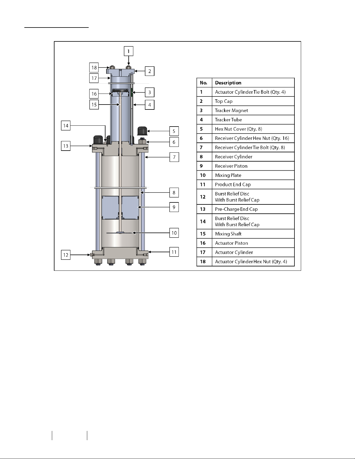
Disassembling the LS-14
Figure 13: LS-14 Maintenance Diagram
6. Disconnect the tubing from the top cap.
7. Disconnect the tubing between the inert gas supply tank and the pre-charge end cap.
8. Remove the actuator cylinder hex nuts from the actuator cylinder tie bolts, and then remove the top cap.
9. Remove the tracker tube and tracker magnet, and then set them aside. Take care not to misplace the tracker tube pins
inside the tracker tube.
10. Slowly slide the actuator cylinder up and off the actuator piston.
11.
Remove the magnet retainer, magnet, and actuator piston from the mixer shaft (Figure 18).
12. Loosen the receiver cylinder hex nuts on the pre-charge end cap, and then loosen the receiver cylinder hex nuts on the
product end cap.
13. Fully unscrew six (6) of the receiver cylinder hex nuts on the pre-charge end cap and their respective receiver cylinder
hex nuts on the product end cap.
14. Remove the six (6) receiver cylinder tie bolts by pulling them up and out of the pre-charge end cap.
15. Fully unscrew and remove the remaining receiver cylinder hex nuts on the pre-charge end cap.
16. Remove the pre-charge end cap from the LS-14.
17. Carefully lift the pre-charge end cap straight up and off the mixer shaft.
IOM-131 MODEL: L S-14 REV: F 13839 West Bellfort St reet, Sugar L and, TX 77498 welker. com Servic e Departm ent 281.491.2331
23
Page 24

18. With the receiver piston still inside, carefully lift the receiver cylinder off the product end cap.
The receiver cylinder is extremely heavy. It may be necessary to have a partner assist in removing the cylinder. Use appropriate
personal protective equipment (PPE) and follow appropriate company policies for heavy lifting.
19. Gripping the mixing shaft above the mixing plate, gently pull the mixing shaft out through the bottom of the receiver
piston, taking care not to scratch the mixing shaft, as scratches may cause seals to leak. If scratches are present, the unit
may need to be repaired or replaced. Contact Welker for service options.
20. From the pre-charge side, slowly push the receiver piston out of the receiver cylinder. Note the position of the top and
bottom of the piston and cylinder for ease of reassembly.
As necessary, use a clean wooden dowel or PVCpipe to gently push the piston out of the cylinder. DONOT use metal objects,
as they may scratch and damage the unit.
IOM-131 MODEL: L S-14 REV: F 13839 West Bellfort St reet, Sugar L and, TX 77498 welker. com Servic e Departm ent 281.491.2331
24
Page 25
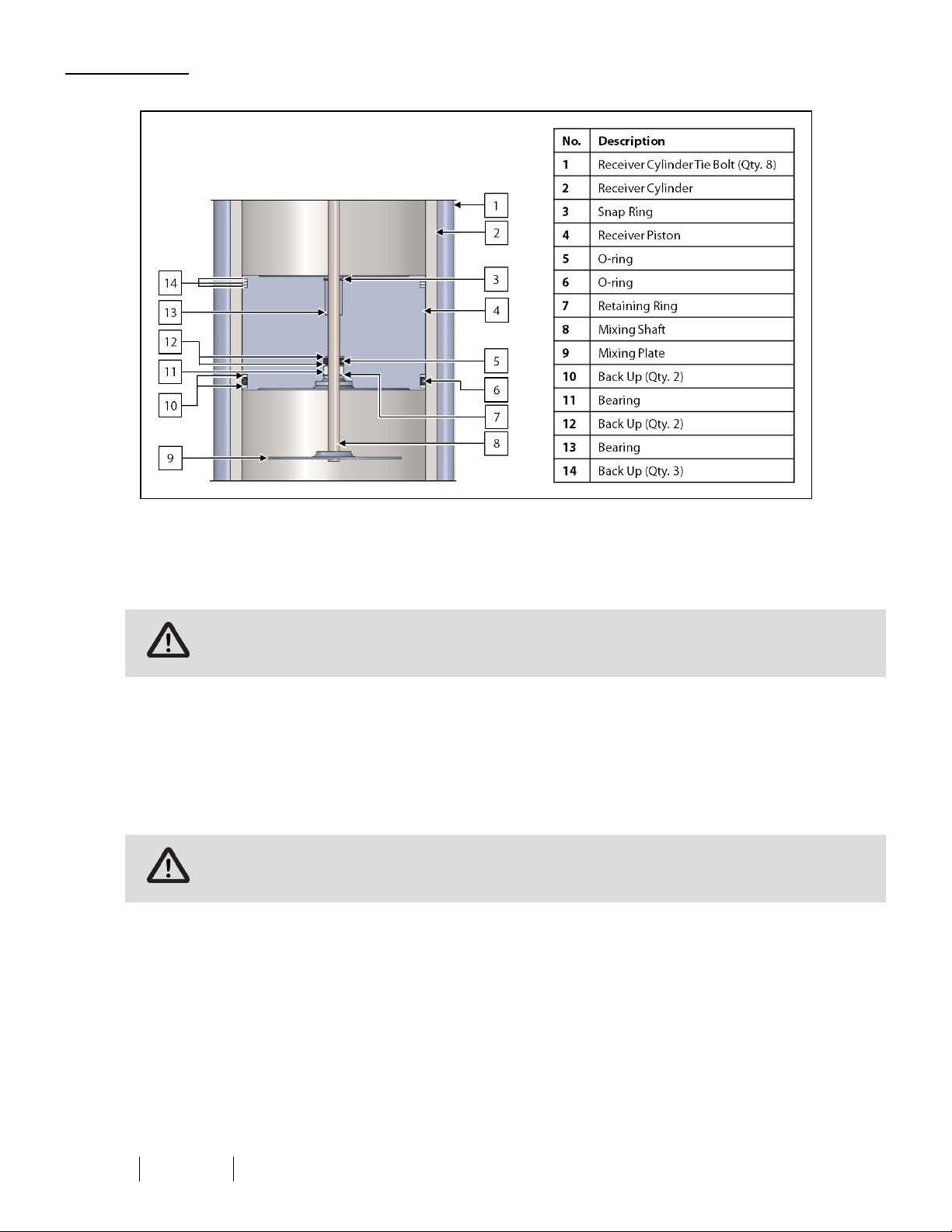
Receiver Cylinder
Figure 14: Receiver Cylinder Maintenance Diagram
21. Closely examine the polished and honed surfaces of the receiver cylinder, as scratches or pits may cause the seals to
leak. If scratches or pits are present, the unit may need to be repaired or replaced. Contact Welker for service options.
22. Lightly lubricate the inside of the receiver cylinder.
DONOTuse a hydrocarbon-based lubricant, as it can leave a residue that can skew laboratory analysis results.
23. Ensure that the bearing in the receiver piston is clean and smooth. Replace as necessary.
24. Replace the back ups, O-rings, retaining ring, and snap ring on the receiver piston.
25. Closely examine the polished and honed surfaces on the mixing shaft, as scratches or pits may cause the seals to leak. If
scratches or pits are present, the unit may need to be repaired or replaced. Contact Welker for service options.
26. Lightly lubricate the mixing shaft.
DONOTuse a hydrocarbon-based lubricant, as it can leave a residue that can skew laboratory analysis results.
27. Insert the mixing shaft into the receiver piston, taking care not to damage the seals. Gently rotate the threads through
the seals.
28. Insert the receiver piston into the receiver cylinder.
IOM-131 MODEL: L S-14 REV: F 13839 West Bellfort St reet, Sugar L and, TX 77498 welker. com Servic e Departm ent 281.491.2331
25
Page 26
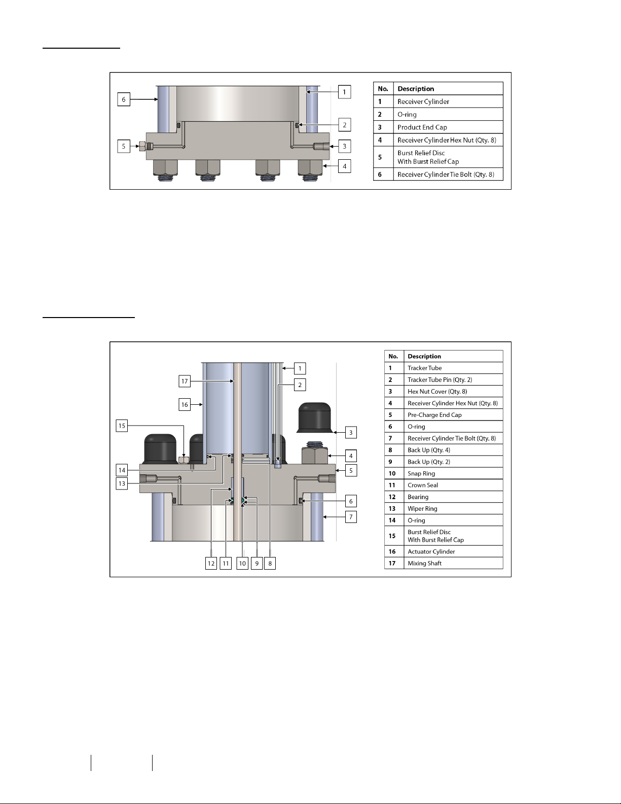
Product End Cap
Figure 15: Product End Cap Maintenance Diagram
29. Replace the O-ring on the product end cap.
30.
If the LS-14 is equipped with a burst relief disc, replace the burst relief disc. Refer to the Installation, Operation, and
Maintenance (IOM) Manual for the burst relief disc for instructions on installing replacement discs.
31. If applicable, tighten the burst relief cap to 25 ft•lb once the replacement burst relief disc has been installed.
32.
If the LS-14 is equipped with an external relief, maintain the relief. Refer to the Installation, Operation, and Maintenance
(IOM) Manual for the external relief for maintenance instructions.
Pre-Charge End Cap
Figure 16: Pre-Charge End Cap Maintenance Diagram
33. Ensure that the bearing in the pre-charge end cap is clean and smooth. Replace as necessary.
34. Replace the wiper ring, O-rings, back ups, snap ring, and crown seal on the pre-charge end cap.
35.
If the LS-14 is equipped with a burst relief disc, replace the burst relief disc. Refer to the Installation, Operation, and
Maintenance (IOM) Manual for the burst relief disc for instructions on installing replacement discs.
36. If applicable, tighten the burst relief cap to 25 ft•lb once the replacement burst relief disc has been installed.
37.
If the LS-14 is equipped with an external relief, maintain the relief. Refer to the Installation, Operation, and Maintenance
(IOM) Manual for the external relief for maintenance instructions.
IOM-131 MODEL: L S-14 REV: F 13839 West Bellfort St reet, Sugar L and, TX 77498 welker. com Servic e Departm ent 281.491.2331
26
Page 27
Reassembling the Receiver Cylinder
38. Place the receiver cylinder onto the product end cap.
39. Carefully place the pre-charge end cap onto the receiver cylinder. The gauge port on the pre-charge end cap should
align with the gauge port on the product end cap.
40. Insert the receiver cylinder tie bolts into the product end cap.
41. Following a cross-bolting sequence, first screw the receiver cylinder hex nuts down two (2) threads on the top of each
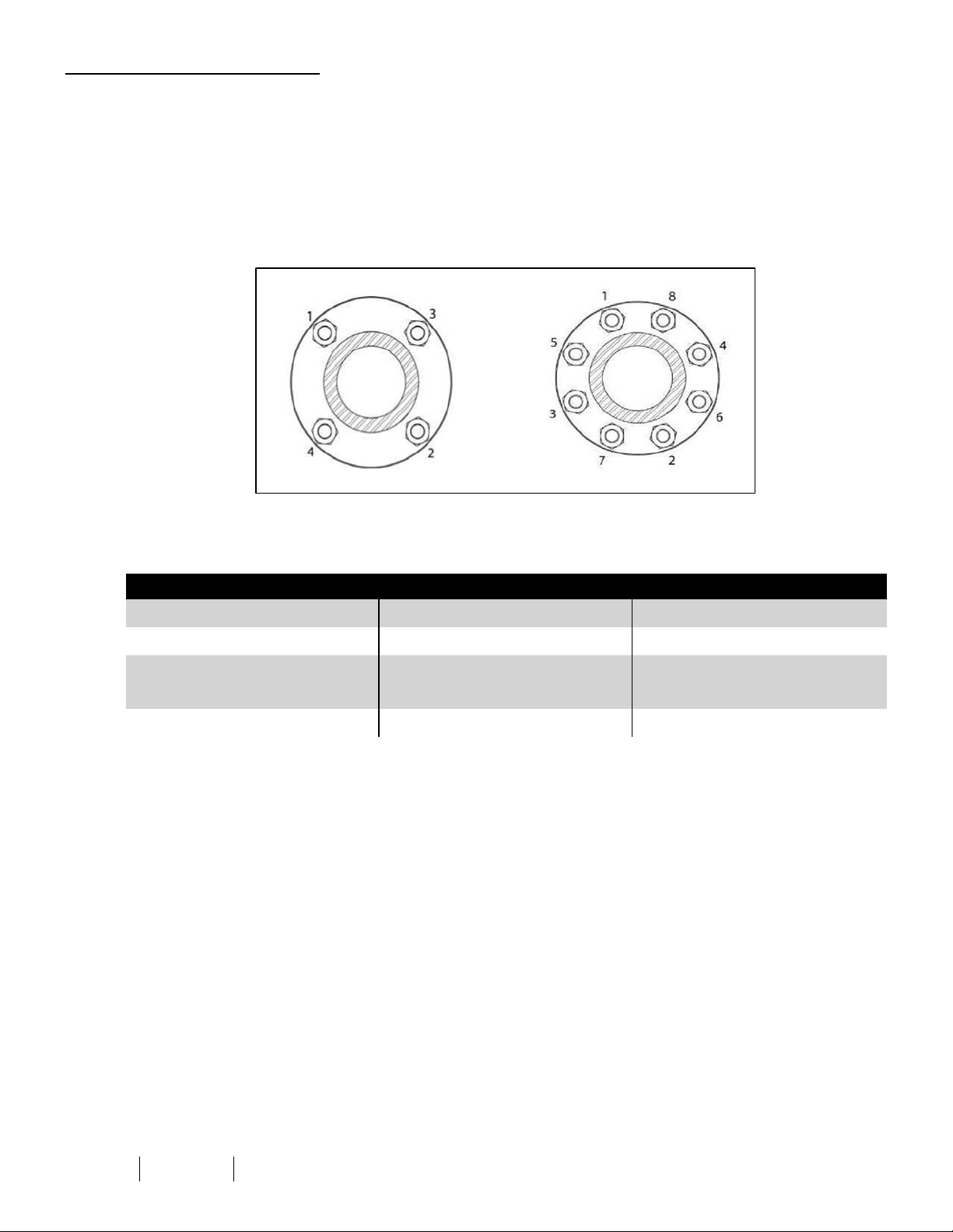
bolt, and then screw the hex nuts up two (2) threads on the bottom of each bolt (Figure 17).
Figure 17: Cross-Bolting Sequence
42. Push each tie bolt up from the bottom, and then hand-tighten the hex nuts on each top bolt.
43.
As necessary, tighten all tie bolts to the correct torque (Table 2).
Table 2: Torque Specifications for Tie Bolts
Tie Bolt Diameter Foot-Pounds (ft•lb) Kilograms per Meter (kg/m)
³⁄₈" 5–6 0.69–0.82
½" 15–20 2.07–2.76
⁵⁄₈" 25–30 3.45–4.14
⁷⁄₈" or 1" 55–65 7.60–8.98
IOM-131 MODEL: L S-14 REV: F 13839 West Bellfort St reet, Sugar L and, TX 77498 welker. com Servic e Departm ent 281.491.2331
27
Page 28
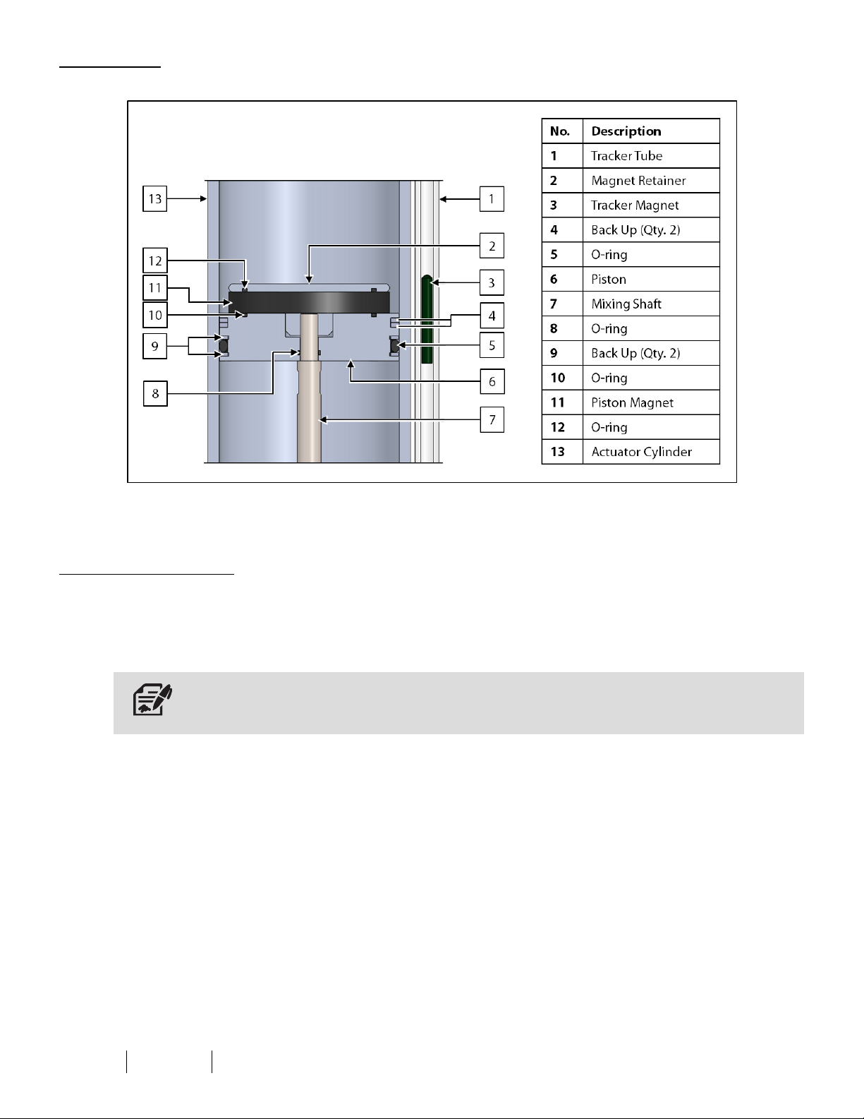
Actuator Piston
Figure 18: Actuator PistonMaintenance Diagram
44. Replace the O-rings and back ups on the actuator piston.
45. Replace the O-ring on the magnet retainer.
Reassembling the Actuator
46. Assemble the actuator piston, magnet, and magnet retainer.
47. Ensure that the tracker magnet and tracker tube pins are inside the tracker tube, and then carefully attach the volume
indicator to the actuator cylinder.
If the tracker tube pins are not inside the tracker tube, the tracker magnet will fall below 0%, yielding an inaccurate reading.
48. Slide the actuator cylinder down into place over the mixing shaft.
IOM-131 MODEL: L S-14 REV: F 13839 West Bellfort St reet, Sugar L and, TX 77498 welker. com Servic e Departm ent 281.491.2331
28
Page 29
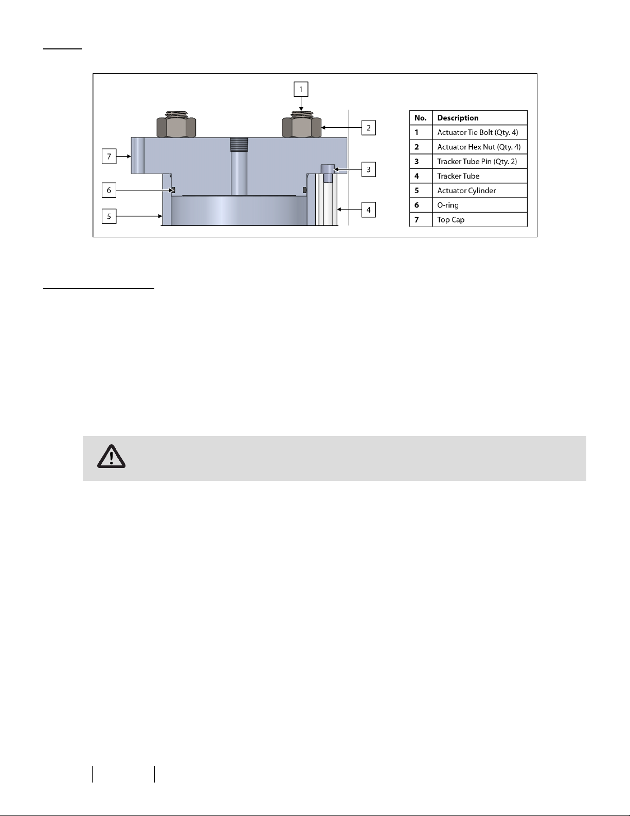
Top Cap
Figure 19: Top Cap Maintenance Diagram
49. Replace the O-ring on the top cap.
Reassembling the LS-14
50. Place the top cap onto the actuator cylinder.
51. Insert the actuator tie bolts into the top cap.
52.
53.
Following a cross-bolting sequence, tighten the actuator hex nuts (Figure 17).
As necessary, tighten all tie bolts to the correct torque (Table 2).
54. Connect the tubing to the top cap.
55. Connect the tubing between the inert gas supply tank and the pre-charge end cap.
56. Check the system for loose fittings. Tighten any loose fittings and replace ferrules where necessary.
57.
Install the system according to the instructions in Section 2.2, Installation, and Section 2.3, Preparing for Sampling.
Check valves for leaks and repair as necessary during reinstallation.
IOM-131 MODEL: L S-14 REV: F 13839 West Bellfort St reet, Sugar L and, TX 77498 welker. com Servic e Departm ent 281.491.2331
29
Page 30

3.3 Troubleshooting
Issues Possible Causes Solutions
The LS-14 will not fill to 80%.
The LS-14 is filling too quickly.
Table 3: LS-14 Troubleshooting
Pre-charge pressure may not be relieving
back to the inert gas supply tank.
Pre-charge pressure may not be supplied
to the LS-14 at the appropriate pressure.
Ensure that valve A and valve C, if
applicable, on the inert gas supply tank
are open during composite sampling to
allow pressure to be relieved back to the
inert gas supply tank from the pre-charge
side as product enters the LS-14 (Figure
10).
Apply additional pre-charge pressure to
the LS-14 until the pre-charge pressure
reaches 50–100 psig above pipeline
operating pressure, not to exceed the
maximum allowable operating pressure
of the equipment.
The tracker magnet is not moving.
The burst disc on the product side
of the LS-14 is leaking.
The burst disc on the pre-charge
side of the LS-14 is leaking.
The sampler may be set at a faster
sampling frequency than desired.
The hydraulic or pneumatic supply may
not be directed below the actuator
piston.
Sample is leaking from the receiver
cylinder.
The lifespan of the burst disc may have
been exceeded.
The valve on the pre-charge side of the
LS-14 may be closed.
Adjust the PLC to sample at the desired
rate. Ensure that the calculations used to
determine the sample frequency are
correct (Figure 9).
Ensure that the mixer lever/button is
tubed to the bottom of the actuator
cylinder.
Ensure that purge/return valve D is closed.
Check for leaks between the sampler and
the receiver cylinder and repair as
necessary.
Replace the burst disc. A more frequent
preventative maintenance schedule may
be required for the burst disc. Do not
exceed 80% volume in the LS-14 to avoid
overpressurizing the receiver cylinder.
Ensure that valve A and valve C, if
applicable, on the inert gas supply tank
are open during composite sampling to
allow pressure to be relieved back to the
inert gas supply tank from the pre-charge
side as product enters the LS-14 (Figure
10).
The lifespan of the burst disc may have
been exceeded.
Replace the burst disc. A more frequent
preventative maintenance schedule may
be required for the burst disc.
IOM-131 MODEL: L S-14 REV: F 13839 West Bellfort St reet, Sugar L and, TX 77498 welker. com Servic e Departm ent 281.491.2331
30
Page 31

Issues Possible Causes Solutions
The regulator is leaking.
Table 3: LS-14 Troubleshooting (Continued)
The poppet assembly may need to be
replaced.
Check the poppet assembly and the seat
on the regulator. Replace as necessary.
Refer to the Installation, Operation, and
Maintenance (IOM) Manual for the
regulator for instructions on maintaining
the regulator.
The pneumatic supply may be too high,
too low, or not operating.
Inspect the pneumatic supply and
regulator to ensure that air is supplied at
the appropriate pressure.
The mixer is not working properly.
The hydraulic supply may be too low or
not operating.
The relief and check valve in the
hydraulic line have failed.
Inspect the electro-hydraulic unit (EHUC).
Add hydraulic oil as necessary. Ensure that
hydraulics is supplied at the appropriate
pressure. If the EHUCis not operating,
refer to the Installation, Operation, and
Maintenance (IOM) Manual for the EHUC.
Maintain the relief and check valve. Refer
to the Installation, Operation, and
Maintenance (IOM) Manuals for the relief
and check valve for instructions.
IOM-131 MODEL: L S-14 REV: F 13839 West Bellfort St reet, Sugar L and, TX 77498 welker. com Servic e Departm ent 281.491.2331
31
Page 32

APPENDIX A: REFERENCEDORATTACHEDDOCUMENTS
WelkerInstallation, Operation, and Maintenance (IOM) Manuals suggested for use with this unit:
l IOM-001: Welker 4P Sample Frequency Controller
l IOM-002: Welker 6Tc Timer/Controller
l IOM-011: Welker CP-2G, CP-5G, CP-35G, and CP-2G With Premium Purge Constant Pressure Sample Cylinders
WithTracker Tube
l IOM-025: Welker IR-1, IR-2, IR-4, and IR-6 Instrument Regulators
l IOM-029: Welker inLoop™ Crude Oil Sampler
l IOM-033: Welker RV-1, RV-2,RV-2CP, andRV-3 Relief Valves
l IOM-041: Welker AVA-1 andAVA-2 Volume Analyzers
l IOM-046: Welker F-4 Filter Dryer
l IOM-056: Welker MPS-2 Gas Sampler
l IOM-105: Welker NV-1 andNV-2 Instrument Valves
l IOM-175: Welker SSO-9MEDInjection Pump
l IOM-182: Welker CV-K Check Valve
Other Installation, Operation, and Maintenance (IOM) Manuals suggested for use with this unit:
l Automatic Timing &Controls 354BSeries Shawnee IIHigh Speed Counter (Welker IOM-V034)
l Circle Seal Controls 500 Series Adjustable Popoff &Inline Relief Valves (Welker IOM-V178)
l Continental Disc Corporation Preparation and Installation of the ½" Standard Type Rupture Disc/Screw Type Holder
Assembly (Welker IOM-V301)
l Gems Sensors Inc. Series Piston-Type FlowSwitches FS-925/926 & FS-927/930 (Welker IOM-V029)
l Magnetrol International, Incorporated Thermatel® Model TD1/TD2 ThermalDispersion Flow/Level/Interface Switch
(Welker IOM-V129)
l MTSSystems Corporation Level Plus® Liquid-Level Sensors With Temposonics® Technology M-Series Model MR Analog
Transmitter (Welker IOM-V036)
l Norgren Micro-Fog® and Oil-Fog Tool Lubricators L73M and L73C (Welker IOM-V013)
l Norgren R83 Cylinder Gas Pressure Regulator For Industrial Gas Systems (Welker IOM-V014)
l Swagelok Company Proportional Relief Valves R Series (Welker IOM-V086)
l TopWorx™ GO™ Switch 10 & 20 Series (Welker IOM-V131)
l Versa Products Company, Inc. C-316 Series Stainless Steel 3-Way and 4-Way Manual, Latching and Key Valves
(Welker IOM-V070)
l WIKA Instrument Corporation Bourdon Tube Pressure Gauges Type 232.53 and Type 233.53 (Welker IOM-V171)
l Wilson Company Standard Hydraulic Power Units (Welker IOM-V009)
Welker drawings and schematics suggested for use with this unit:
l Assembly Drawing: AD245.HCRN (CRN-Certified LS-14 With Optional Hydraulic Mixer Actuation)
l Assembly Drawing: AD245CRN (CRN-Certified Standard LS-14)
l Assembly Drawing: AD245CV (Standard LS-14)
IOM-131 MODEL: L S-14 REV: F 13839 West Bellfort St reet, Sugar L and, TX 77498 welker. com Servic e Departm ent 281.491.2331
32
Page 33

NOTES
____________________________________________________________________________________________________
____________________________________________________________________________________________________
____________________________________________________________________________________________________
____________________________________________________________________________________________________
____________________________________________________________________________________________________
____________________________________________________________________________________________________
____________________________________________________________________________________________________
____________________________________________________________________________________________________
____________________________________________________________________________________________________
____________________________________________________________________________________________________
____________________________________________________________________________________________________
____________________________________________________________________________________________________
____________________________________________________________________________________________________
____________________________________________________________________________________________________
____________________________________________________________________________________________________
____________________________________________________________________________________________________
____________________________________________________________________________________________________
____________________________________________________________________________________________________
____________________________________________________________________________________________________
13839 West Bellfort Street
Sugar Land, TX77498
Phone: 281.491.2331
welker.com
IOM-131 MODEL: L S-14 REV: F 13839 West Bellfort St reet, Sugar L and, TX 77498 welker. com Servic e Departm ent 281.491.2331
33
 Loading...