

Page 1

Installation, Operation, and
Maintenance Manual
®
Welker
Manual Insertion Probe
Instrument Regulator
Model
IRM-4SS
The information in this manual has been carefully checked for accuracy and is intended to be used as a guide for
the installation, operation, and maintenance of the Welker equipment described above. Correct operating and/or
installation techniques, howe ver, ar e the responsibilit y of the e nd user. Welker reserves the right to make changes
to this and all products in order to improve performance and reliability.
© Copyright 2007, Welker, Inc.
13839 West Bellfort
Sugar Land, Texas 77498-1671
U.S.A.
Tel.: (800) 776-7267
Tel.: (281) 491-2331
Fax: (281) 491-8344
www.welkereng.com
Page 2

TABLE OF CONTENT S
1. GENERAL 3
1.1 I
1.2 D
1.3
2. INSTALLATION INSTRUCTIONS 6
NTRODUCTION 3
ESCRIPTION OF PRODUCT 3
SPECIFICATIONS 4
2.1 G
2.2
2.3
2.4 R
ENERAL 6
IMPORTANT INFORMATION 6
INSTALLATION INSTRUCTIONS 6
ETRACTING THE PROBE 8
3. MAINTENANCE 9
3.1 G
3.2 I
3.3
3.4 P
Welker®, Welker Jet®, and WelkerScope® are Registered Trademar k s owned by Welker, Inc.
ENERAL 9
NSTRUMENT REGULATOR MAINTENANCE 10
RELIEF VALVE (RV-1) MAINTENANCE 11
ROBE MAINTENANCE 12
IOM-089 Page 2 of 13
Manual Insertion Prob e I n s tr ument Regulator
Rev: B
Last updated: 9/8/2009
Page 3
SPECIFICATIONS
1. GENERAL
1.1 Introduction
We appreciate your business and your choice of Welker products. The installation,
operation, and maintenance liability for this product becomes that of the purchaser at the
time of receipt. Readi ng the applicable Installation, Operation, and Maintenance (IOM)
Manual prior to installation and operation of this equipment is required for a full
understanding of its application and performance prior to use. If you have any questions,
please call 1-800-776-7267 in the USA or 1-281-491-2331.
The following procedures have been written for use with standard Welker parts and
equipment. Assemblies that have been modified may have additional requirements and
specifications that are not listed in this manual.
Notes, Warnings, and Cautions
Notes emphasize i nformation or set it off from the surrounding text.
Caution messages appear before procedures that, if not observed, could result
in damage to equipment.
Warnings alert users to a specific procedure or practice th at, if
not followed correctly, could cause personal injury.
1.2 Description of Product
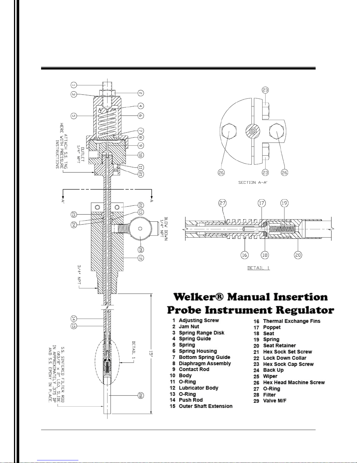
The Welker Probe Instrument Regulator is designed to
serve as a probe and a regulator combination while
minimizing the Joule-Thomson effect by design. Supply
enters through the tip of the probe and is regulated to a
reduced pressure and immediately passes through thermal
exchange fins before exiting the flowing stream in the
pipeline. The body houses the output adjustment and
spring along with output port, gauge port, and safety relief
port.
This probe can be manually inserted and or retracted
without interfering or venting pressure within 500 PSIG.
IOM-089 Page 3 of 13
Manual Insertion Prob e I n s tr ument Regulator
Rev: B
Last updated: 9/8/2009
Page 4
SPECIFICATIONS
1.3 Specifications
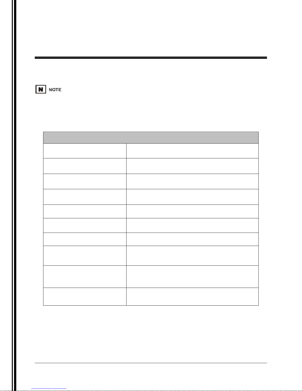
The specifications listed in this Section are generalized for this equipment. Welker can modify the
equipment according to your company’s needs. However, please note that the specifications may vary
depending on the customization of your produc t.
Specifications
Table 1
Products
Materials of Construction
Insertion Length
Viscosity Range
Sample Outlet Connection
Pipeline Connection
Products
Maximum Allowable Operating
Pressure*
Insertion Pressure*
Natural gas or other gases or liquid s compatible with the
materials of construction
®
316 Stainless Steel, Viton
, PTFE (others available)
18" (457mm) Standard {others available in 1" (25.4mm)
increments}
0.009cp to 2,000cp @68°
1
/4" NPT
3
/4" or 1" NP T
F (20° C
Natural gas or other gases or liquid s compatible with the
materials of construction
2,160 PSIG @ -20°
F to 100° F
(148 bar @ -29° C to 37° C)
Manual insertion and retraction up to 500 PSIG ONLY.
Operating pressure can then be increased to 2,160 PSIG MAX.
Output Range*
* Maximum allowable pressures and output ranges may be lower depending on specifications of the pipel ine connectio n device.
IOM-089 Page 4 of 13
Manual Insertion Prob e I n s tr ument Regulator
Rev: B
Last updated: 9/8/2009
0-100 psi @ -20° F to 100 ° F
(0-6 bar @ -29° C to 37° C)
Page 5
SPECIFICATIONS
IOM-089 Page 5 of 13
Manual Insertion Prob e I n s tr ument Regulator
Rev: B
Last updated: 9/8/2009
Page 6
INSTALLATION & OPERATIONS
2. INSTALLATION INSTRUCTIONS
2.1 General
After unpacking the unit, check it for compliance and for any damages that may
have occurred during shipment.
Claims for damages caused during shipping must be initiated by the receiver and directed to
the shippi ng carrier. Welker is not responsible for any damages caused from mishandling
by the shipping company.
When sealing fittings with PTFE tape, refer to the pr oper sealing instructions for the tape
used.
2.2 Important Information
• The most common cause for repairs to an adjustable probe occurs when the
pipeline isolation valve closes on the probe while the probe is still inserted into the
pipeline. Avoid this practice.
• Operate the unit slowly and smoothly when inserting and retracting the unit to
avoid unnecessary slamming.
• Avoid rough handling of the probe and unnecessary bending of the probe shaft.
The shaft has a polished surface that travels through a seal.
• The entire instrument should be treated with care.
2.3 Installation Instructions
The preferred location for ins t allation i nto t he pip eline is i n a straig ht Section of inlet piping before the
flowing stream is subjected to turns and impingements that can produce aerosols. Aerosols can
contaminate the sample being taken.
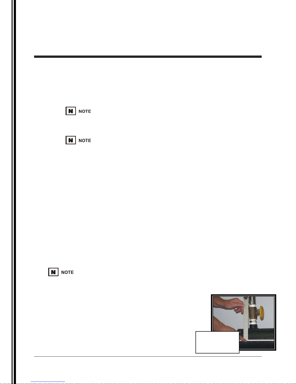
1. Determine the amount of insertion travel desired by
measuring from the top of the pipeline isolation valve to
the middle one-third of the pipeline (See Figure 1).
2. With the probe on a flat surface, slide the probe shaft
through the pipeline connection until the desired
insertion length is obtained.
Figure 1
Insertion
Le ngth
IOM-089 Page 6 of 13
Manual Insertion Prob e I n s tr ument Regulator
Rev: B
Last updated: 9/8/2009
Page 7
INSTALLATION & OPERATIONS
2.3 Installation Instructions (Continued)
3. With a wrench, tighten the lock collar to the insertion shaft firmly.
4. Completely retract the probe shaft.
5. Install the probe assembly to the pipeline isolation valve.
6. Close the appropriate pipeline valves in order to depressurize the pipeline to 500 PSI or
lower for probe installation.
7. Open the pipeline isolation valve.
8. Insert the probe by pushing directly down on the probe valve using both hands for
stability.
9. Use tubing to connect from the outlet port on the
regulator to the inlet of the instrument.
10. Install the lock down bolts (Part 26).
11. Check for leaks.
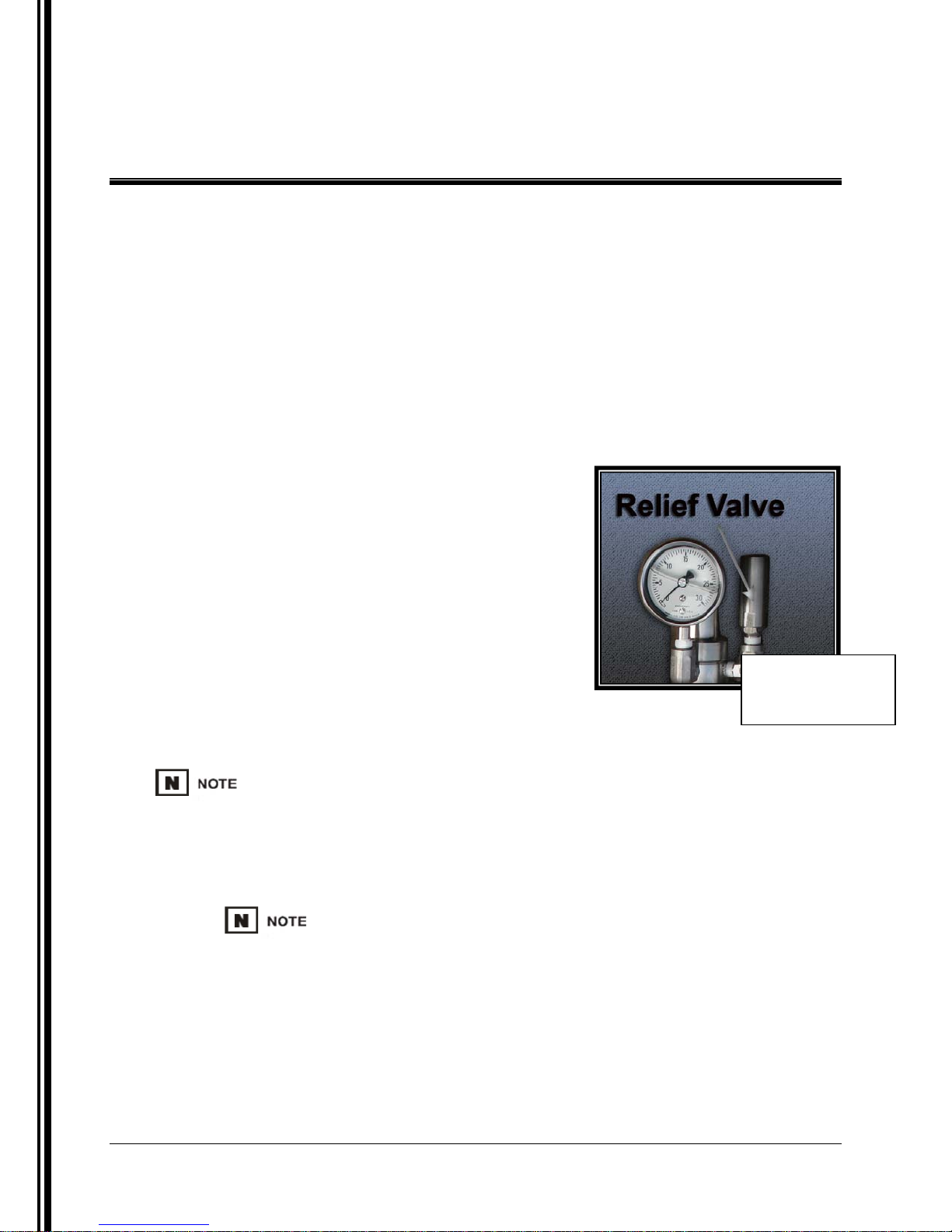
12. Connect a gauge to the gauge port in the
regulator.
13. If necessary, follow steps in number 14 of this
Section, using a safe auxiliary gas supply to set
the relief valve to the proper pressure. If relief is
Relief Valve
preset, skip to number 15 of this Section.
14. Set the Relief Valve (RV-1) ( Figure 3):
If requested, Welker can preset Welker relief valves prior to shipment.
• Use a hex wrench to adjust the spring tension in the relief valve for positive shut-off.
• Adjust the relief to the desired set point.
Some models will vent to atmosphere, while others can be piped to another system if
required.
• The relief valve is now in operation.
15. Connect the set relief valve to the relief valve port in the regulator.
Figure 3
IOM-089 Page 7 of 13
Manual Insertion Prob e I n s tr ument Regulator
Rev: B
Last updated: 9/8/2009
Page 8
INSTALLATION & OPERATIONS
2.3 Installation Instructions (Continued)
16. Make sure the pipeline is providing pressure to the regulator. The gauge should read
pipeline pressure.
17. Set the Instrument Regulator to desired pressure setting:
• Turn the inlet supply to pressurize the regulator inlet.
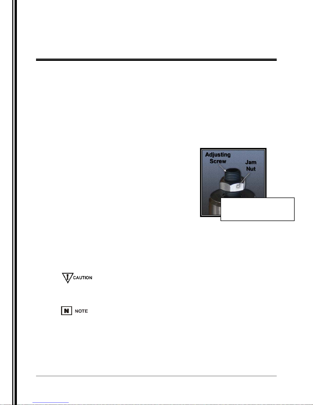
• Loosen or tighten the adjusting screw until the gauge reads the desired pressure for
outlet (See Figure 2).
• Tighten the jam nut (Part 2) on the adjusting screw (Part 1) to secure it into place.
• The regulator is now in operation.
18. The probe is now in serv ice. P ipeline can now be
restored to full operating pressure.
2.4 Retracting the Probe
1. Loosen the jam nut (Part 2), and turn the
adjusting screw counterclockwise until there is no
output from the regulator.
Setting the Instrument
Figure 2
Regula tor
2. Depressurize the pipeline to 500 PSI or lower, and disconnect any tubing from the
probe assembly.
3. Firmly grasp the probe valve.
4. Push down on the valve while loosening the lock down bolts (Part 26).
5. Slowly let the probe retract.
Make sure that the probe is completely retracted before proceeding.
6. Close the pipeline isolation valve.
If the probe is being withdrawn from the pipeline to run a pig, stop at step 6 of
this Section.
7. Remove the probe assembl y from the pipeline isolation valve.
8. The probe assembly is now ready for maintenance or to be moved to another location.
IOM-089 Page 8 of 13
Manual Insertion Prob e I n s tr ument Regulator
Rev: B
Last updated: 9/8/2009
Page 9
MAINTENANCE
3. MAINTENANCE
3.1 General
Prior to maintenance or disassembly of the unit, it is advisable to have a repair kit handy
for the system in cas e of unexpected wea r or faulty seals. All maintenance and cle aning
of the unit should be done on a smooth, clean surface.
We recommend that t he unit hav e annual mainte nance under no rmal o perating co nditions. In
the case of severe service, dirty conditions, excessive cycling usage, or other unique
applications that may subject the equipment to unpredictable circumstances, a more frequent
maintenance schedule may be appropriate.
New seals supplied in spare Parts kits are not lubricated. They should be lightly coated with
lubrication grease (Dow Corning 111 [DC 111] or equivalent lubricant) before they are installed into
the equipment. This helps wi th the installa tion of the sea ls while reducin g the ris k of d amage when
positioning them on the parts.
Maintenance on the inst rument regulator sho ul d not be performed until the regulator has been
isolated from all pressure.
Recommended Tools
It would be advisable to have the following tools available for maintenance of the unit; however,
tools used will vary depending on probe model.
• Small hex key set
• 6" adjustable wrench
• 10" adjustable wrench
• 10" channel lock pliers
• Fine grit sandpaper
• Flat blade screwdriver
IOM-089 Page 9 of 13
Manual Insertion Prob e I n s tr ument Regulator
Rev: B
Last updated: 9/8/2009
Page 10
MAINTENANCE
3.2 Instrument Regulator Maintenance
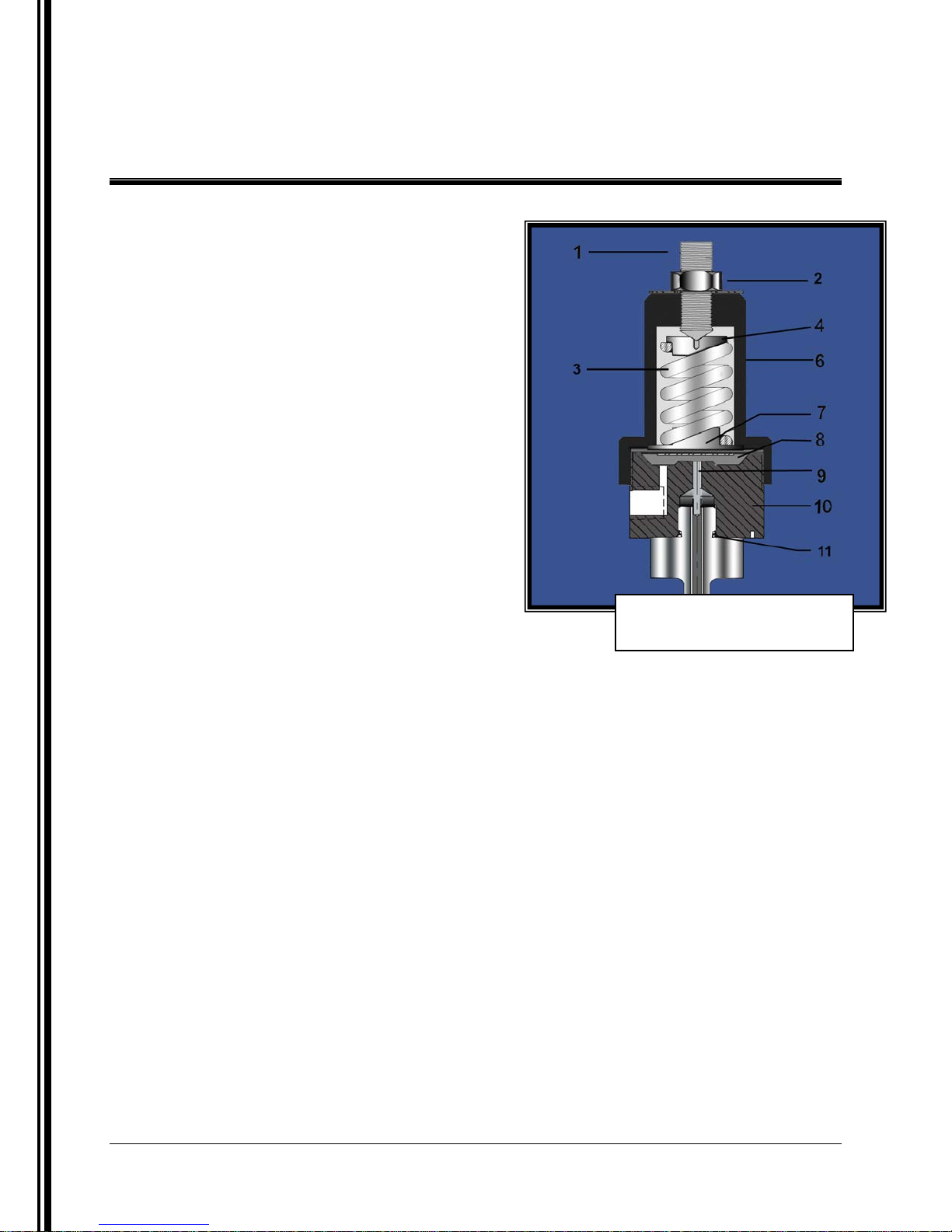
(See Figure 3)
1. Follow instructions in Section 2.2 to
retract the probe and remove the
instrument from the pipeline.
2. Disconnect the instrument from the
regulator outlet port
3. Loosen the adjusting nut (Part 2) on
the adjusting screw (Part 1).
4. Loosen the adjusting screw to relieve
tension on the spring (Part 3).
5. Disassemble Diaphragm Assembly:
a) Unscrew the spring housing (Part 6)
and remove.
b) Remove the top spring guide (Part 4)
and the spring (Part 3).
Instrument Regulator
Figure 3
c) Remove the bottom spring guide (Part 7).
d) Remove the diaphragm assembly (Part 8). Inspect for wear, and replace if
necessary.
e) Set the diaphragm back into place.
f) Set the bottom spring guide back into place on top of the diaphragm.
6. Set the spring (Part 3) back into place.
7. Set the top spring guide (Part 4) back into place on top of the spring.
8. Reattach the spring housing (Part 6) securely. Hand-tighten the housing.
9. Proceed to Section 3.3 for relief valve maintenance.
IOM-089 Page 10 of 13
Manual Insertion Prob e I n s tr ument Regulator
Rev: B
Last updated: 9/8/2009
Page 11
MAINTENANCE
3.3 Relief Valve (RV-1) Maintenance
(See Figure 4)
1. Isolate and depressurize the relief valve from the supply source.
2. Remove the relief valve from the supply.
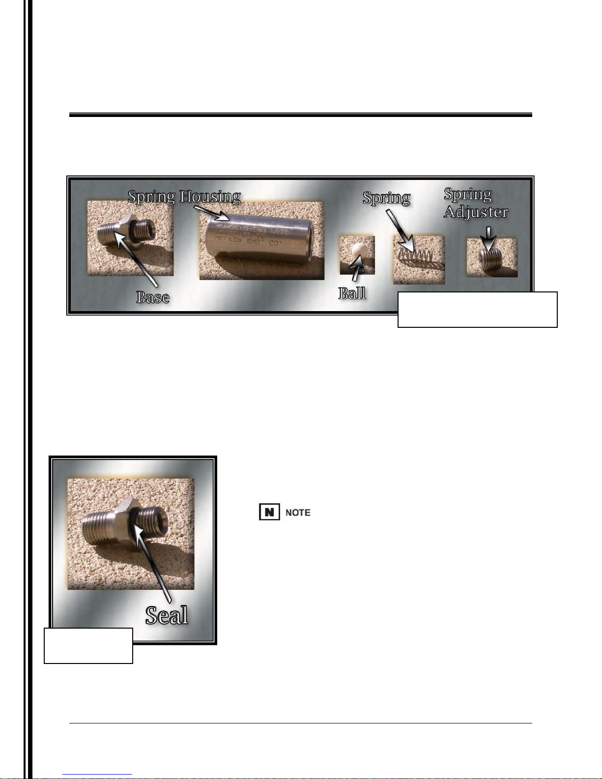
Figure 4
Relief Valve (RV-1D)
Figure 5
Seal
3. Remove the spring adjuster, spring and ball.
4. If the spring is in good condition, it can be reused.
5. Check the ball for nicks and scratches and replace if necessary.
6. Unscrew the base from the spring housing and replace the seal (See Figure 5).
7. Screw the base and spring housing back together.
8. Drop the ball and spring into the spring housing.
The ball must r est on the se al. If the ba ll rests on the
metal trim, then the relief will not seat.
9. Replace the spring adjuster.
10. The relief valve is ready to reinstall and reset.
11. Proceed to Section 3.4 for probe maintenance
instructions
IOM-089 Page 11 of 13
Manual Insertion Prob e I n s tr ument Regulator
Rev: B
Last updated: 9/8/2009
Page 12
MAINTENANCE
3.4 Probe Maintenance Instructions
(See Figure 5)
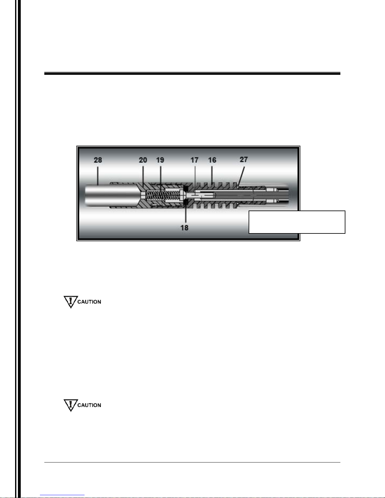
1. Use a pair of channel lock pliers as a backup to hold the thermal fins (Part 16)
while using another pair to remove the seat retainer (Part 20).
Figure 5
Thermal Fins & Retainer
2. Remove the poppet spring (Part 19) and the poppet (Part 17).
3. Use a pointed instrument to carefully pick the seat (Part 18) out of the body of the
thermal fin.
4. Examine the poppe t and t he s eat (P art 18) for sc ra t ches . If scr at ches a r e pr e s ent , t he
part will need to be replaced.
Debris or scratches on either the poppet or the seat will prevent positive shut-off of the regulator.
5. Use solvent to clean the filter (Part 28) in the retainer.
6. Guide the poppet into the seat.
7. Replace the spring and seat retainer.
8. Tighten the seat retainer firmly.
9. Replace the O-ring (Part 27) on the shaft.
10. If there is a shaft extension, remove the extension from the thermal fins.
11. Reattach the thermal fins to the shaft. Tighten firmly.
When reattac hing the b ase to the body, make sure that the contact rod and push rod are carefully
installed and lined up correctly. The push rod should fit easily over the poppet and should not
stack on top of it. If the rod is stacked on top of the poppet, the device will not be able to be
reassembled properly.
IOM-089 Page 12 of 13
Manual Insertion Prob e I n s tr ument Regulator
Rev: B
Last updated: 9/8/2009
Page 13

13839 West Bellfort, Sugar Land, Texas 77498-1671
Phone: (281) 491-2331
Fax: (281) 491-8344
Toll Free: (800) 776-7267
Web Page: www.welkereng.com
 Loading...