

Page 1

INSTALLATION, OPERATION, ANDMAINTENANCEMANUAL
WELKER®CYLINDERSTEAM&VACUUMCLEANER
MODEL
CSVC
DRAWING NUMBERS
AD881CA
AD881CB
MANUALNUMBER
IOM-128
REVISION
Rev. B, 3/16/2016
Page 2

TABLEOF CONTENTS
SAFETY 3
1. PRODUCT INFORMATION 4
1.1 Introduction 4
1.2 Product Description 4
1.3 Safety Warning 4
1.4 Important Information 4
1.5 Specifications 5
1.6 Equipment Diagrams 6
2. INSTALLATION & OPERATION 11
2.1 Before You Begin 11
2.2 Installation 12
2.3 Operation 13
3. MAINTENANCE 19
3.1 Before You Begin 19
3.2 Maintenance 20
APPENDIX 21
A: Referenced or Attached Documents 21
Welker®, Welker Jet®, WelkerScope®, and OdorEyes® are Registered Trademarks owned by Welker, Inc.
IOM-128 MODEL: CSVC REV: B 13839 West Bellfort St reet Sugar Land, TX 77498 welker. com Servic e Depart ment 281.491.2331
2
Page 3
SAFETY
IMPORTANTSAFETYINFORMATION
READALLINSTRUCTIONS
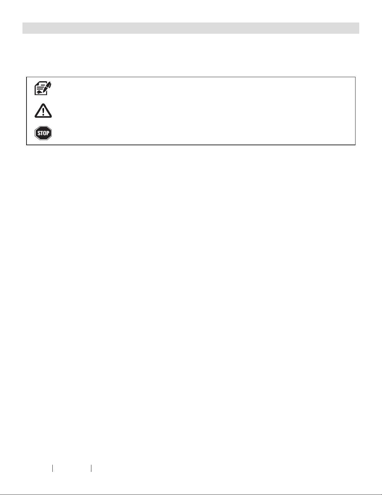
Notes emphasize information and/or provide additional information to assist the user.
Caution messages appear before procedures that could result in damage to equipment if not observed.
Warning messages appear before procedures that could result in personal injury if not observed.
This m anual is intended to be used as a basic installation and operation guide fo r the Welker® Cylinder Steam & Vacuum Cleaner, CSVC. For comprehensive
instructions, please refer to the IOMManua ls for each individual component. A list of relevant component IOM Manuals is provided in Appendix A of this manual.
The information in this manual has been ca refully checked fo r accuracy and is intended to be used as a guide for the installation, operation, and maintenance of
the Welker® equipment described in this manual. Correct installation and operation, however, are the responsibility of the end user. Welker reserves the right to make
changes to this manual and all products in order to improve performanc e and reliability.
BEFOREYOUBEGIN
Read t hese instructions completely and carefully.
IMPORTANT - Savethese instructions for l ocal inspector's use.
IMPORTANT - Observeall governing codes and ordinances.
Note to Installer - Leavethese instructions with the end user.
Note to End User - Keep these instructions for future reference.
Installation of this CylinderSteam & Vacuum Cleaner is of a mechanical and electrical nature.
Properinstallation isthe responsibility of the installer. Product failure due to improperinstallation isnot covered underthe warranty.
If you received a damaged CylinderSteam & Vacuum Cleaner, please contact a Welker®representativeimmediately.
Phone: 281.491.2331
Address: 13839West Bellfort Street
Sugar Land, TX 77498
IOM-128 MODEL: CSVC REV: B 13839 West Bellfort St reet Sugar Land, TX 77498 welker. com Servic e Depart ment 281.491.2331
3
Page 4

SECTION 1: PRODUCTINFORMATION
1.1 Introduction
We appreciate your business and your choice of Welker® products. The installation, operation, and maintenance liability for this
equipment becomes that of the purchaser at the time of receipt. Reading the applicable Installation, Operation, and
Maintenance (IOM) Manuals prior to installation and operation of this equipment is required for a full understanding of its
application and performance prior to use.*
If you have any questions, please call Welker at 1-281-491-2331.
*The following proc edures have been written for use with standard Welker® pa rts and equipment. Assemblies that have been modified may have additional
requirements and specifications that are not listed in this manua l.
1.2 Product Description
The Welker® CSVC Cylinder Steam & Vacuum Cleaner is an effective cleaning system that utilizes heat from saturated and superheated steam to clean sample cylinders. Unlike hot water, steam evenly distributes heat to all surfaces. Moisture content of steam
can be quickly and easily controlled by regulating the inlet pressure. The use of a steam separator will reduce moisture in
saturated steam to less than one percent (1%). This system does not require any chemicals, saves on water usage, and facilitates
the simultaneous cleaning of multiple cylinders. In short, the CSVC is an efficient, environmentally-friendly system for removing
contaminants inside sample cylinders.
Welker may custom design the CSVC to suit the particular application and specifications of each customer.
1.3 Safety Warning
1. Steam may be dangerous if the proper precautions are not taken. Hot surfaces and release of live steam may cause
serious bodily injury. Follow safety and correct operating procedures when working with steam. When operating the
system, wear appropriate personal protective equipment (PPE), which could include gloves that cover the forearms.
2. Exposure to steam is hazardous. If not properly controlled, steam may cause serious bodily injury and/or property
damage.
1.4 Important Information
1. Cylinders must be completely emptied and drained before being connected to the CSVC.
2. A damaged steam hose may result in serious personal injury and/or property damage.
3. Never transport a cylinder with pressure exceeding DOTregulations as established in 49 C.F.R. In cases where the
cylinder may be exposed to varying temperatures, do not allow the cylinder to exceed its maximum allowable
operating pressure (MAOP).
4. Handle the cylinder with care. Protect the cylinder and valves during transport.
5. Once analysis is complete, the cylinder should be emptied safely and placed in a safe area.
6.
Welker recommends cleaning and leak testing the cylinder after each use. Refer to the Installation, Operation, and
Maintenance (IOM) Manual for the Welker® SC Single Cavity Sample Cylinder for instructions.
IOM-128 MODEL: CSVC REV: B 13839 West Bellfort St reet Sugar Land, TX 77498 welker. com Servic e Depart ment 281.491.2331
4
Page 5

1.5 Specifications
The specifications listed in this section are generalized for this equipment. Welker can modify the equipment according t o your
company's needs. Please note that the specifications may vary depending on the customizations of your
equipment.
Table 1: CSVC Specifications
Application
Maximum Allowable Operating Pressure
Steam Temperature Range
Connections
Cleaning of Sample Cylinders
90 psig (6.2 barg)
212 °F to 331 °F (100 °C to 166 °C)
½" FNPT (Standard)
¾" FNPT
Utility Requirement Water Supply: Up to 100 psig (6.8 barg)
Electrical Connection
AC 120 V
AC 480 V, 3 Phase
300 cc (Standard)
Cylinder Volume
500 cc
1000 cc
Up to 6 Cylinders (Standard)
System Cylinder Capacity
Up to 12 Cylinders
Up to 24 Cylinders
Blowdown Separator
Insulated Tubing
Steam Generator
Features
Steam Traps
Swagelok® Quick-Connects
Thermostatically Controlled Heater
Vacuum Pump
FasMate® Quick-Connects
Options
Water Pump
Welker® SG-3 Sight Glasses
IOM-128 MODEL: CSVC REV: B 13839 West Bellfort St reet Sugar Land, TX 77498 welker. com Servic e Depart ment 281.491.2331
5
Page 6
1.6 Equipment Diagrams
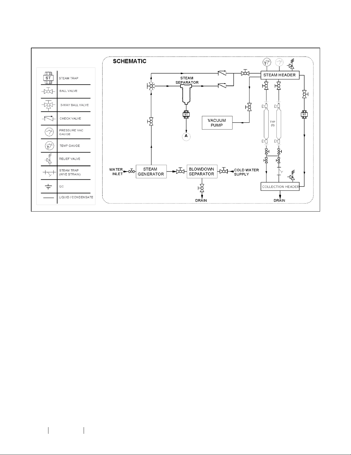
Figure 1: CSVC Schematic
IOM-128 MODEL: CSVC REV: B 13839 West Bellfort St reet Sugar Land, TX 77498 welker. com Servic e Depart ment 281.491.2331
6
Page 7
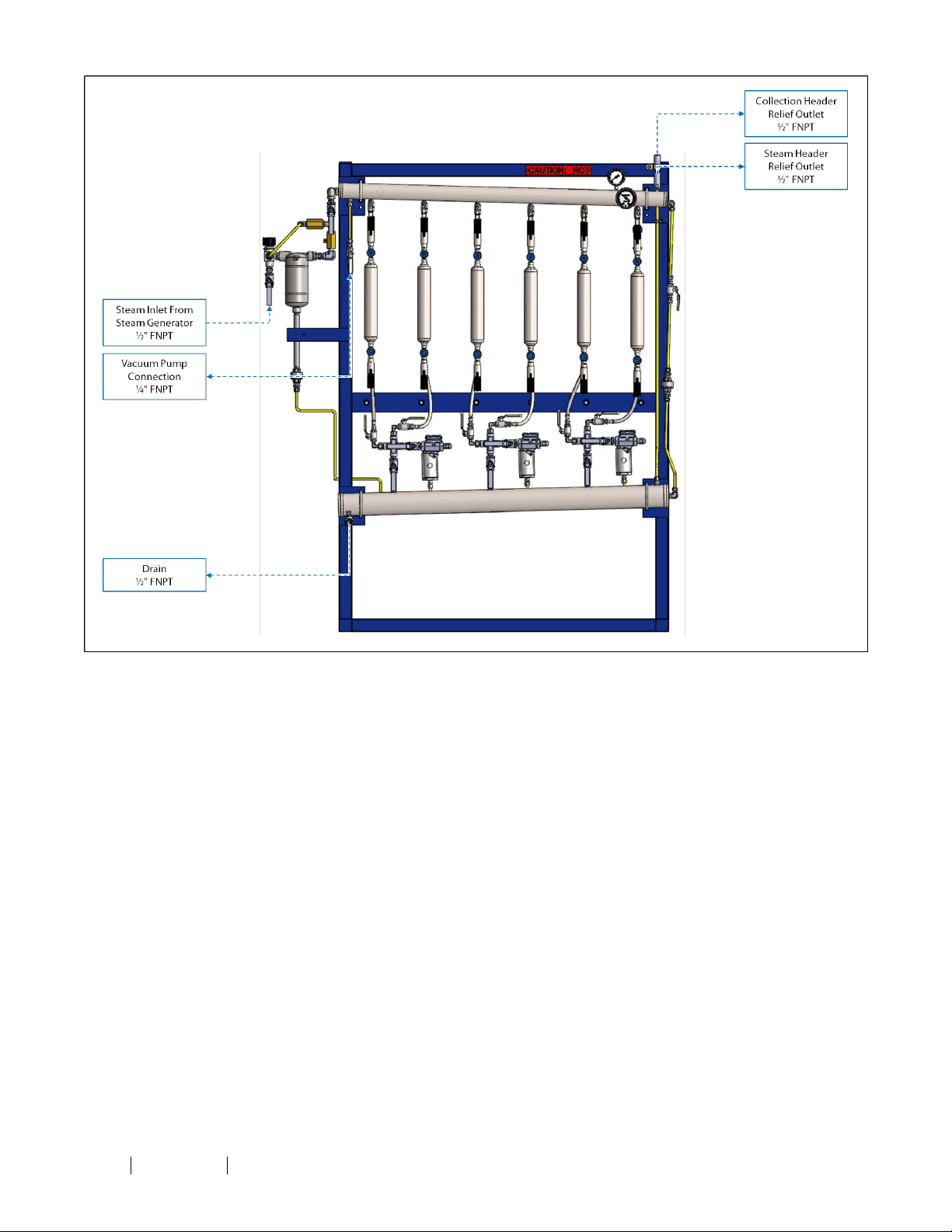
Figure 2: CSVC Connections Diagram (Shown With Optional FasMate® Quick-Connects)
IOM-128 MODEL: CSVC REV: B 13839 West Bellfort St reet Sugar Land, TX 77498 welker. com Servic e Depart ment 281.491.2331
7
Page 8
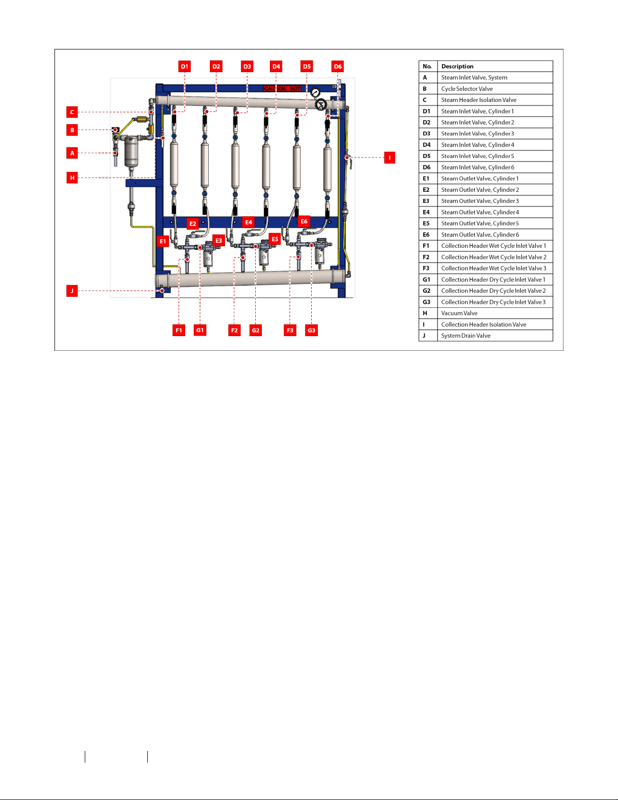
Figure 3: CSVC Valve Diagram (Shown With Optional FasMate® Quick-Connects)
IOM-128 MODEL: CSVC REV: B 13839 West Bellfort St reet Sugar Land, TX 77498 welker. com Servic e Depart ment 281.491.2331
8
Page 9
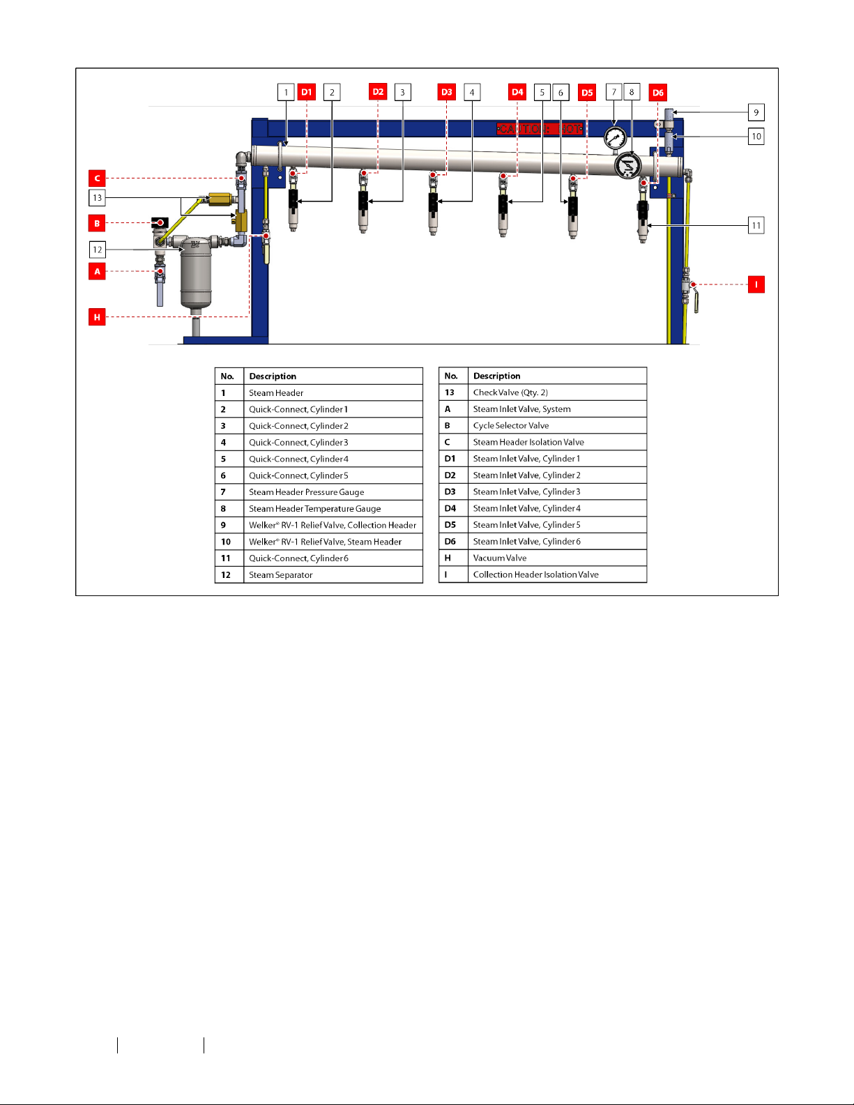
Figure 4: Steam Header Diagram (Shown With Optional FasMate® Quick-Connects)
IOM-128 MODEL: CSVC REV: B 13839 West Bellfort St reet Sugar Land, TX 77498 welker. com Servic e Depart ment 281.491.2331
9
Page 10
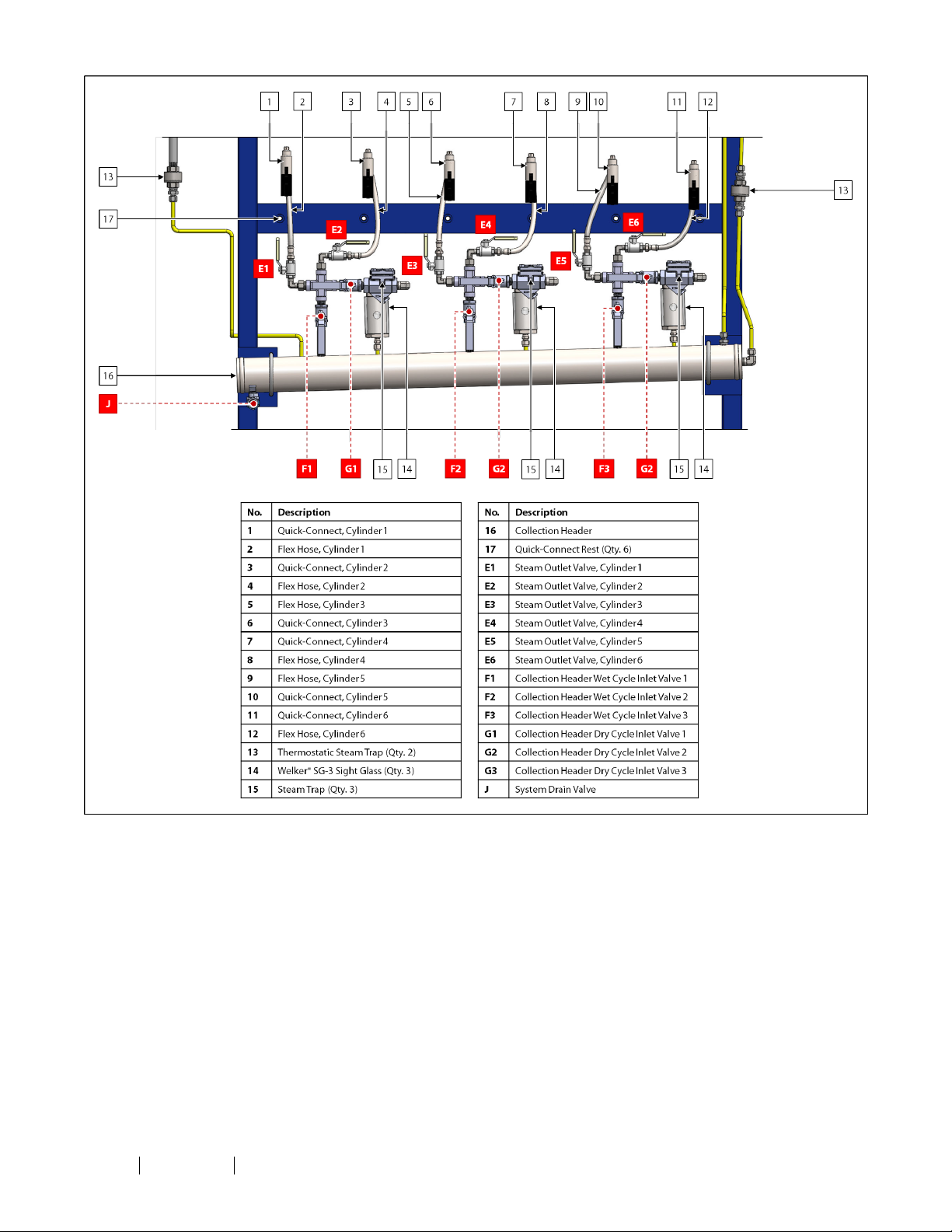
Figure 5: Collection Header Diagram (Shown With Optional FasMate® Quick-Connects)
IOM-128 MODEL: CSVC REV: B 13839 West Bellfort St reet Sugar Land, TX 77498 welker. com Servic e Depart ment 281.491.2331
10
Page 11
2.1 Before You Begin
SECTION 2: INSTALLATION & OPERATION
After unpacking the unit, check the equipment for compliance and any damage that may haveoccurred during shipment.
Immediately contact a Welker®representative if you received damagedequipment.
When sealing fittings with PTFE tape,refer to the propersealing instructions for the brand used.
The Cylinder Steam & Vacuum Cleaner will shipskid-mounted and "hard-tube" connected with manufacturer-supplied fittings
and hardware.However,the customerwill need to supply some tubing and fittings in orderto complete the installation of the
system.
IOM-128 MODEL: CSVC REV: B 13839 West Bellfort St reet Sugar Land, TX 77498 welker. com Servic e Depart ment 281.491.2331
11
Page 12
2.2 Installation
1. Install the CSVC in the desired location.
Welker recommends the CSVCbe install ed in a location whereaccess to valves, cylinders, auxiliary equipment, and utilities is not
restricted and where relief valves can be safely vented to prevent potential injury.
2.
3.
Ensure that all valves are closed (Figure 3).
Set the relief valve on the steam header to the appropriate pressure (Figure 4). Refer to the Installation, Operation, and
Maintenance (IOM) Manual for the Welker® RV-1 Relief Valve for instructions on setting the relief.
4.
Set the relief valve on the collection header (Figure 4). This relief should be set approximately 10 psig below the relief
valve on the steam header. Refer to the Installation, Operation, and Maintenance (IOM) Manual for the RV-1 for
instructions on setting the relief.
Setting the relief on the collection headerto a pressurelowerthan that of the reliefon the steam headerensures proper
functioning of the steam traps.
5.
6.
7.
8.
9.
If desired, use ½" tubing to connect from the relief valves to an appropriate venting location (Figure 2).
Using ½" tubing, connect from system drain valve J to an appropriate container (Figure 2).
Using the provided ½" steam hose, connect from the steam generator to the steam inlet (Figure 2).
Using the provided ½" vacuum hose, connect from the vacuum pump to vacuum valve H (Figure 2).
Connect the customer-supplied water supply to the inlet on the steam generator (Figure 1).
There is a 10 psig pressure drop across the steam generator from the water inlet to the steam outlet.
10.
12
Connect the customer-supplied cold water supply to the inlet on the blowdown separator (Figure 1).
Thisunit requires a col d water connection. Welker recommends that the inlet to the blowdown separator be lower than the
sight glass of the steam generator to ensuresafe drainageduring blowdown.
The blowdown separator reducestemperatures and pressuresto safe l evels for dischargeto the drain or sewer.During
blowdown, the blowdown separator separatesliquid from vapor to prevent live steam discharge to city drains.
IOM-128 MODEL: CSVC REV: B 13839 West Bellfort St reet Sugar Land, TX 77498 welker. com Servic e Depart ment 281.491.2331
Page 13
2.3 Operation
Steam Generator
To ensure safe operation of the steam generator, follow all manufacturerinstructions, including PPE recommendations and
safety instructions. Referto the Installation, Operation, and Maintenanc e (IOM) Manual for the steam generator for operating
instructions.
1.
2.
Ensure that all valves are closed (Figure 3).
Close the drain valve and steam outlet valve on the steam generator, and then turn on the customer water supply. Allow
the water level to rise approximately halfway up the steam generator sight glass before operating the steam generator.
This may take several minutes.
3.
Connect an appropriate electrical supply to the steam generator. Refer to the Installation, Operation, andMaintenance
(IOM) Manual for the steam generator for the manufacturer's wiring instructions.
4.
Set the thermostat to the desired steam temperature, and then turn ON the boiler switch to start the steam generator
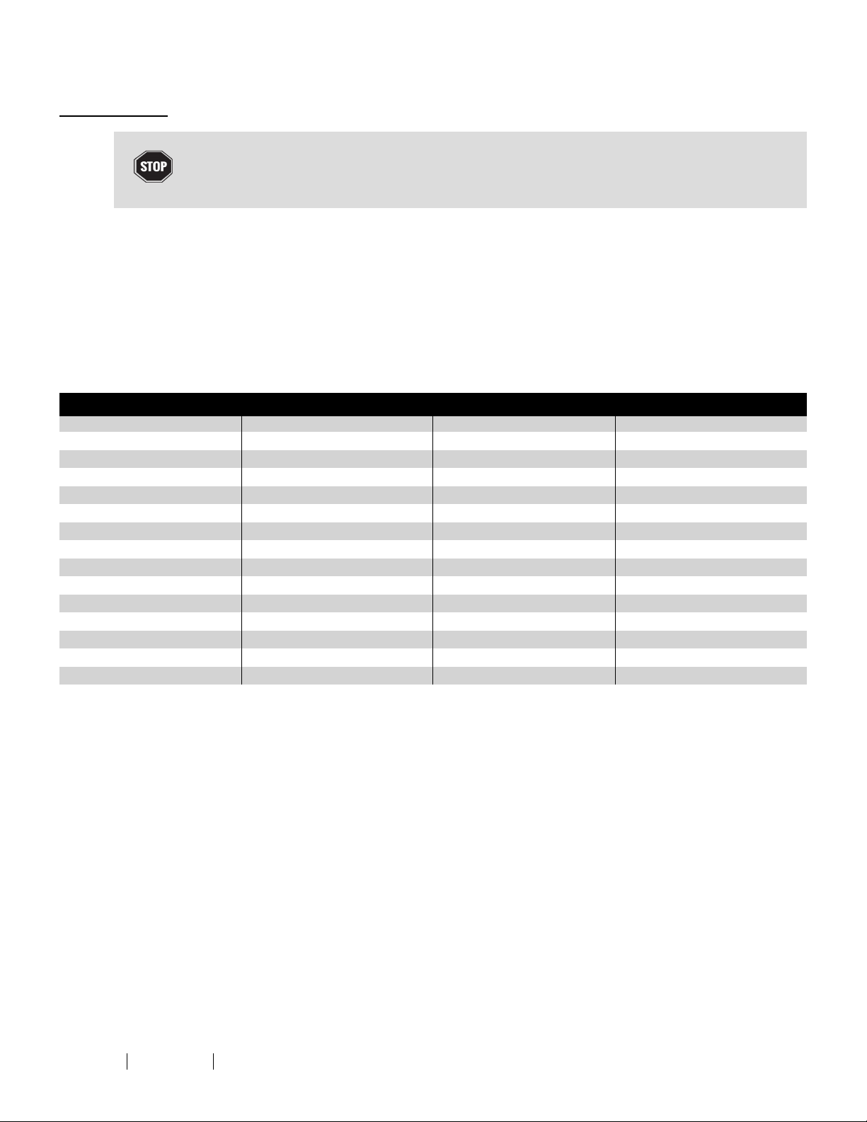
(Table 2). Allow at least thirty (30) minutes for the steam to reach the desired temperature.
Table 2: Steam Temperature Settings
Water Inlet Pressure (psig) Steam Temperature (°F) Water Inlet Pressure (psig) Steam Temperature (°F)
10
15
20
25
0
1
2
3
4
5
6
7
8
9
212 30
216 35
219 40
222 45
224 50
227 55
230 60
232 65
235 70
237 75
240 80
250 85
259 90
267 –
274
281
287
292
298
303
307
312
316
320
324
328
331
–
5.
13
Once the steam has reached the desired temperature, open the steam outlet valve on the steam generator.
IOM-128 MODEL: CSVC REV: B 13839 West Bellfort St reet Sugar Land, TX 77498 welker. com Servic e Depart ment 281.491.2331
Page 14
Steam System
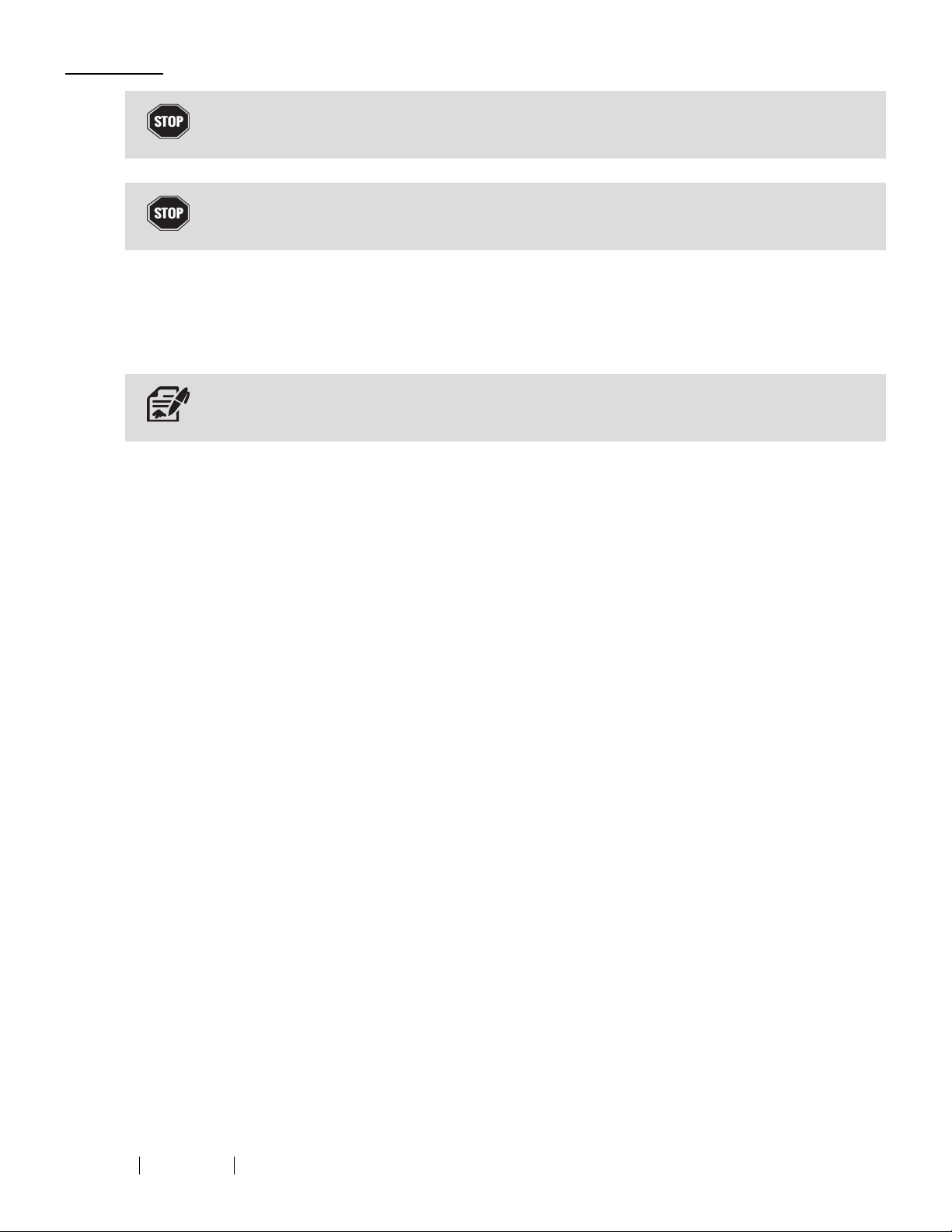
Failureto properly follow the manufacturer'srecommended proceduresfor the care, maintenance, and storageof the steam
hoses may result in serious bodily injury and/or property damage.
Only specially trained personnel should engage in operating or testing procedures that requireparticular skills and/or training.
Failureto comply may result in damage to the hoses,other property damage,and/or serious bodily injury.
10.
11.
12.
13.
14.
6.
7.
Ensure that the steam has reached the desired temperature.
Connect the inlet of the customer-supplied Welker® SC Single Cavity Sample Cylinder to the quick-connect on the
steam header (Figure 4).
8.
9.
Connect the outlet of the customer-supplied SC to the flex hose with quick-connect on the collection header (Figure 5).
When connecting the outlet of the SC to t he coll ection header, Welkerrecommends positioning the flex hose so that access to
the collection headervalves is not restricted.
Open both valves on the SC.
Open system drain valve J on the collection header (Figure 3 or Figure 5). If the CSVC is equipped with a second
collection header, open system drain valve J on the second collection header as necessary.
Open steam outlet valve E for the installed SC (Figure 3 or Figure 4).
Open steam inlet valve D for the installed SC (Figure 3 or Figure 4).
As necessary, repeat steps 7-12 for any additional SCs.
Open steam header isolation valve C and collection header isolation valve I (Figure 3 or Figure 4).
IOM-128 MODEL: CSVC REV: B 13839 West Bellfort St reet Sugar Land, TX 77498 welker. com Servic e Depart ment 281.491.2331
14
Page 15
Wet Cycle
15.
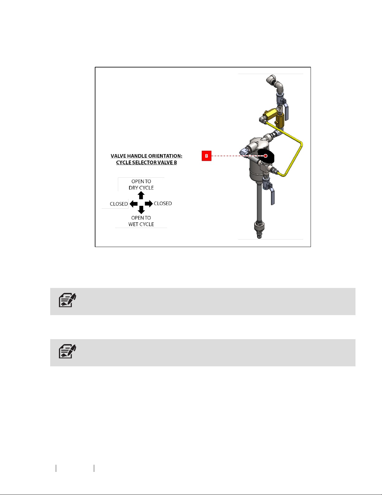
Manually turn the handle on cycle selector valve B so that the arrow on the handle points away from the steam separator
(Figure 6). This will open the valve to the wet cycle.
Figure 6: Cycle Selector Valve B Orientation
16.
17.
18.
19.
Open collection header wet cycle inlet valve F for all installed SCs (Figure 3 or Figure 5).
Open steam inlet valve A to start the wet cycle (Figure 3). Saturated contaminants will drain to the container connected
to the drain.
During the wet cycle, the steam generator generates saturated steam, which dissolves and flushes cont aminants from the
sample cylinders.
Allow the wet cycle to run for the appropriate amount of time.
The time requiredto completely clean the sample cylindersis dependent on the set temperature of the steam generator, the
water inlet pressure, the t ype of contaminant(s), and the number of sample cylinders.
Once the sample cylinders are free of visible contaminants or considered clean in accordance with the end user's
specifications, close steam inlet valve A (Figure 3). This ends the wet cycle.
IOM-128 MODEL: CSVC REV: B 13839 West Bellfort St reet Sugar Land, TX 77498 welker. com Servic e Depart ment 281.491.2331
15
Page 16
DryCycle
20.
21.
22.
23.
Manually turn the handle on cycle selector valve B so that the arrow on the handle points toward the steam separator
(Figure 6). This will open the valve to the dry cycle.
Cycle selector valve B will be HOT.
Open collection header dry cycle inlet valve G and close collection header wet cycle inlet valve F for the installed SCs
(Figure 3 or Figure 5).
Open steam inlet valve A to start the dry cycle (Figure 3).
During the dry cycle, saturated steam is diverted to t he steam separator,which removes up to 99.8%of moisture.A steam trap
downstream of the sample cylindersdischarges condensate without allowing t he escapeof live steam. The steam trap and
continued input of heat allow steam to be contained, increasing the temperature at which the cylindersare maintained.The
cycle further heats the system to facilitate "baking" of any residueremaining in the sample cyl inders.
Allow the dry cycle to run until the SCs are clean.
The time requiredto completely clean the sample cylindersis dependent on the set temperature of the steam generator, the
water inlet pressure, the t ype of contaminant(s), and the number of sample cylinders.
24.
25.
26.
27.
Once the sample cylinders are considered clean in accordance with the end user's specifications, close steam inlet valve
A (Figure 3). This ends the dry cycle.
Open collection header wet cycle inlet valve F and close collection header dry cycle inlet valve G for the installed SCs
(Figure 3 or Figure 5).
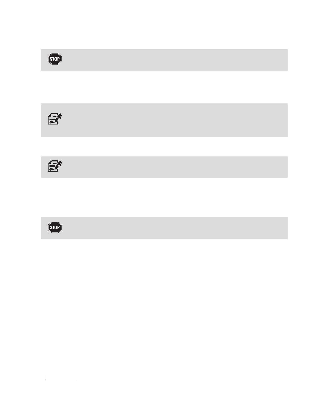
The sample cylinders must be drained prior to disconnecting t he quick-connects. Failure to drainthe sample cylinderspriorto
disconnecting t he quick-connects may result in damage to the equipment and/or injury to the operator.
Close steam header isolation valve C on each steam header used (Figure 3 or Figure 4).
If a vacuum will not be pulled on the SCs, continue to step 28. If a vacuum will be pulled on the SCs, proceed to step
35.
IOM-128 MODEL: CSVC REV: B 13839 West Bellfort St reet Sugar Land, TX 77498 welker. com Servic e Depart ment 281.491.2331
16
Page 17
Vacuum System
No Vacuum
The SCs will be HOT.Allow t he SCs to cool prior to proceeding.
28.
29.
30.
31.
32.
33.
34.
Turn OFF the thermostat to the steam generator.
Close steam inlet valve D and close steam outlet valve E on the flex hose for all installed SCs (Figure 3 or Figure 5).
Close both valves on eachSC.
Disconnect the SCs from the CSVC. If applicable, install the quick-connects to the corresponding quick-connect rests
(Figure 5).
The flex hoses will be HOT.
Open steam header isolation valve C and steam inlet valve A to relieve pressure in the steam header (Figure 3 or Figure
5).
Once pressure has been relieved from the steam header, close steam inlet valve A (Figure 3 or Figure 4).
Welker recommends a daily blowdown of the steam generator. Refer to the Installation, Operation, and Maintenance
(IOM) Manual for the steam generator for instructions.
Power must be OFFwhen the steam generator is drained.
IOM-128 MODEL: CSVC REV: B 13839 West Bellfort St reet Sugar Land, TX 77498 welker. com Servic e Depart ment 281.491.2331
17
Page 18
Pulling a Vacuum
35.
36.
37.
38.
39.
40.
41.
42.
43.
44.
45.
Turn OFF the thermostat on the steam generator.
Close steam outlet valve E on the flex hose for all installed SCs (Figure 3 or Figure 5).
Close collection header isolation valve I (Figure 3 or Figure 5).
Close the bottom valve on all installed SCs.
Turn ONthe vacuum pump.
Open vacuum valve H to pull a vacuum on the SCs (Figure 3). The steam header pressure gauge will display how much
vacuum has been pulled on the SCs.
The time requiredto pul l the desired vacuum is dependent on the sample cylinder volume.
If desired, close the top valve on the SCs to maintain the vacuum on the SCs.
Close vacuum valve H (Figure 3 or Figure 4).
Turn OFF the vacuum pump.
Close steam inlet valve D (Figure 3 or Figure 5).
Disconnect the SCs from the CSVC. If applicable, install the quick-connects to the corresponding quick-connect rests
(Figure 5).
The flex hoses will be HOT.
46.
47.
48.
49.
Open collection header isolation valve I (Figure 3 or Figure 4).
Open steam header isolation valve C and steam inlet valve A to relieve pressure in the steam header (Figure 3 or Figure
4).
Once pressure has been relieved from the steam header, close steam inlet valve A (Figure 3 or Figure 4).
Welker recommends daily blowdown of the steam generator. Refer to the Installation, Operation, and Maintenance
(IOM) Manual for the steam generator for instructions.
Power must be OFFwhen the steam generator is drained.
IOM-128 MODEL: CSVC REV: B 13839 West Bellfort St reet Sugar Land, TX 77498 welker. com Servic e Depart ment 281.491.2331
18
Page 19
3.1 Before You Begin
SECTION 3: MAINTENANCE
1.
Welker recommends that the unit have standard yearly maintenance under normal operating conditions.
In cases of severe service, dirty conditions, excessive usage, or other unique applications that may lead to excess wear
on the unit, a more frequent maintenance schedule may be appropriate.
2. Prior to maintenance or disassembly of the unit, it is advisable to have a repair kit available for repairs of the system in
case of unexpected wear or faulty seals.
New seals supplied in spareparts kits should be lightly lubricated before being installed to ease the installation of the seals and
reducethe risk of damage when positioning them on parts. Wipe excess lubricant from the seals, as it may adversely affect
analytical instrument results.
For sample-exposedseals, Welker recommends non-hydrocarbon-basedlubricants, such as Krytox®.
For non-sample-exposed seals, Welker recommends either non-hydrocarbon-based lubricants or silicone-based lubricants, such
as Molykote® 111.
After the seals are install ed, t he outer diameter of shafts and innerdiameter of cylinders may be lubricated to allow smooth
transition of parts.
3. All maintenance and cleaning of the unit should be performed on a smooth, clean surface.
4. Welker recommends having the following tools available for maintenance. Please note that the exact tools required may
vary by model.
a. 10" Adjustable Wrench (Qty. 2)
b. Flat Head Screwdriver
c. Seal Pick
d. Tubing Cutters
IOM-128 MODEL: CSVC REV: B 13839 West Bellfort St reet Sugar Land, TX 77498 welker. com Servic e Depart ment 281.491.2331
19
Page 20
3.2 Maintenance
1. Routinely inspect the steam separator and steam traps for buildup, clogging, corrosion, and other damage. Refer to the
Installation, Operation, and Maintenance (IOM) Manual for the steam generator and for the steam traps for inspection
and maintenance instructions.
Propersteam separator and steam trap maintenance is essential to a steam system. Faulty steam traps not only waste energy,
but also can contribute t o pipe erosion due t o poor water quality and contaminants allowed to pass downstream. A poor
maintenance program will increase energy losses,decrease reliability, reduce steam quality, and may affect production
downtime.
The frequency of inspection should be determinedby application.
2.
Maintain the steam generator. Refer to the Installation, Operation, and Maintenance (IOM) Manual for the steam
generator for maintenance instructions.
IOM-128 MODEL: CSVC REV: B 13839 West Bellfort St reet Sugar Land, TX 77498 welker. com Servic e Depart ment 281.491.2331
20
Page 21

APPENDIX A: REFERENCEDOR ATTACHEDDOCUMENTS
Welker®Installation, Operation, and Maintenance (IOM) Manuals suggested for use with this unit:
l IOM-033: Welker® RV-1, RV-2, RV-2CP, andRV-3 Relief Valves
l IOM-146: Welker® SCSingle Cavity Sample Cylinder
l IOM-172: Welker® SG-3 Sight Glass
Other Installation, Operation, and Maintenance (IOM) Manuals suggested for use with this unit:
l Apollo Valves 76-100 Series Stainless Steel BallValve withMounting Pad 1/4" - 1" (Welker® IOM-V141)
l Ashcroft® BISeries Bi-Metal Thermometers (Welker® IOM-V235)
l Ashcroft® Type 1008S Stainless Steel Case Gauge withStainless Steel System (Welker® IOM-V242)
l Chromalox® Type CMB Electric Steam Generator (Welker® IOM-V049)
l Chromalox® Steam Boilers (Welker® IOM-V052)
l Dekker Vacuum Technologies, Inc. DuraVane Lubricated Rotary Vane Pump forSaturated Air (Wet) Service RVL031W
(Welker® IOM-V246)
l FasTest Inc. FasMate® FN and FX Series Connectors (Welker® IOM-V245)
l McMaster-Carr Supply Company Extra-Flexible Nylon Tubing (Welker® IOM-V248)
l McMaster-Carr Supply Company Red Steam Hose (Welker® IOM-V247)
l McMaster-Carr Supply Company Super High-Pressure CheckValves (Welker® IOM-V251)
l Swagelok® Hose and Flexible Tubing (Welker® IOM-V176)
l Swagelok® One-Piece Instrumentation BallValves 40G Series and 40 Series (Welker® IOM-V085)
l Swagelok® Quick-Connects QC, QF, QM, and QTMSeries (Welker® IOM-V088)
l TLV® Balanced Pressure Thermostatic Steam Trap Model L21S/L32S (Welker® IOM-V249)
l TLV® Balanced Pressure Thermostatic Steam Trap Model LV21 (Welker® IOM-V051)
l TLV® Cyclone Separator Model DC7 (Welker® IOM-V050)
Welker® drawings and schematics suggested for use with this unit:
l Assembly Drawing: AD881CA (For up to 24 Sample Cylinders)
l Assembly Drawing: AD881CB (For up to 6 Sample Cylinders; With Optional FasMate® Quick-Connects and Welker® Sight
Glasses)
IOM-128 MODEL: CSVC REV: B 13839 West Bellfort St reet Sugar Land, TX 77498 welker. com Servic e Depart ment 281.491.2331
21
Page 22

NOTES
____________________________________________________________________________________________________
____________________________________________________________________________________________________
____________________________________________________________________________________________________
____________________________________________________________________________________________________
____________________________________________________________________________________________________
____________________________________________________________________________________________________
____________________________________________________________________________________________________
____________________________________________________________________________________________________
____________________________________________________________________________________________________
____________________________________________________________________________________________________
____________________________________________________________________________________________________
____________________________________________________________________________________________________
____________________________________________________________________________________________________
____________________________________________________________________________________________________
____________________________________________________________________________________________________
____________________________________________________________________________________________________
____________________________________________________________________________________________________
____________________________________________________________________________________________________
____________________________________________________________________________________________________
13839 West Bellfort Street
Sugar Land, TX77498
Phone: 281.491.2331
welker.com
IOM-128 MODEL: CSVC REV: B 13839 West Bellfort St reet Sugar Land, TX 77498 welker. com Servic e Depart ment 281.491.2331
22
 Loading...