

Page 1

INSTALLATION, OPERATION, ANDMAINTENANCEMANUAL
WELKER ADJUSTABLEPROBE
MODELS
AP-3
AP-3F
DRAWING NUMBERS
AD126BU
AD126CO
AD126DR
AD126EH
MANUALNUMBER
IOM-009
REVISION
Rev. D, 10/19/2018
Page 2

TABLEOF CONTENTS
SAFETY 3
1. PRODUCT INFORMATION 4
1.1 Introduction 4
1.2 Product Description 4
1.3 Specifications 5
1.4 Equipment Diagrams 6
2. INSTALLATION & OPERATION 8
2.1 Before You Begin 8
2.2 Preparing the AP-3 for Installation 8
2.3 Installing the AP-3 10
2.4 Retracting the AP-3 11
3. MAINTENANCE 12
3.1 Before You Begin 12
3.2 Maintenance 12
APPENDIX 15
A: Referenced or Attached Documents 15
Copyright © 2018 Welker,Inc. All rights reserved. Welker®, W Welker®, Wlogo, WelkerScope®, Welker Jet®, andOdorEyes®areregistered trademarks of Welker,Inc.
IOM-009 MODELS: AP-3 and A P-3F REV: D 13839 West Bellfort St reet, Sugar L and, TX 77498 welker. com Servic e Departm ent 281.491.2331
2
Page 3
SAFETY
IMPORTANTSAFETYINFORMATION
READALLINSTRUCTIONS
Notes emphasize information and/or provide additional information to assist the user.
Caution messages appear before procedures that could result in damage to equipment if not observed.
Warning messages appear before procedures that could result in personal injury if not observed.
This manual is intended to be used as a basic installation a nd operation g uide for the Welker Adjustable Probes, AP-3 and AP-3F. For com prehensive instructions,
please refer to the IOM Manua ls for each individual component. A list of relevant comp onent IOM Manua ls is provided in Appendix A of this manual.
The informa tion in this manu al has been carefully chec ked for accurac y and is intended to be used a s a guide for the installation, operation, and maintenance o f
the Welker equipment described in this manual. Correct installation and operation, however, are the respo nsibility of the en d user. Welker reserves the right to ma ke
cha nges to this man ual and a ll products in order to improve p erformance and reliability.
BEFOREYOUBEGIN
Read these instructions completely and carefully.
IMPORTANT - Save these instructions for local inspector's use.
IMPORTANT - Observe all governing codes and ordinances.
Note to Installer - Leave these instructions with the end user.
Note to End User - Keep these instructions for future reference.
Installation of this Adjustable Probe is of a mechanical nature.
Proper installation is the responsibility of the installer. Product failure due to improper installation is not covered under the warranty.
If you received a damaged Adjustable Probe, please contact a Welker representative immediately.
Phone: 281.491.2331
Address: 13839 West Bellfort Street
Sugar Land, TX 77498
IOM-009 MODELS: AP-3 and A P-3F REV: D 13839 West Bellfort St reet, Sugar L and, TX 77498 welker. com Servic e Departm ent 281.491.2331
3
Page 4

SECTION 1: PRODUCTINFORMATION
1.1 Introduction
We appreciate your business and your choice of Welker products. The installation, operation, and maintenance liability for this
equipment becomes that of the purchaser at the time of receipt. Reading the applicable Installation, Operation, and
Maintenance (IOM) Manuals prior to installation and operation of this equipment is required for a full understanding of its
application and performance prior to use.*
If you have any questions, please call Welker at 1-281-491-2331.
*The following p roced ures have been written for use with standard Welker pa rts and eq uipment. Assemblies that have been modified may have additional
requirements and specifications that are not listed in this manual.
1.2 Product Description
The Welker AP-3 Adjustable Probe is designed for use in systems where it is desirable to insert and retract the probe while the
pipeline remains pressurized. When used with a pipeline isolation valve, the AP-3 can be safely inserted and retracted manually
without interfering or venting pressure when operating pressure is reduced to the appropriate level.
Welker may custom design the AP-3 to suit the particular application and specifications of each customer.
IOM-009 MODELS: AP-3 and A P-3F REV: D 13839 West Bellfort St reet, Sugar L and, TX 77498 welker. com Servic e Departm ent 281.491.2331
4
Page 5

1.3 Specifications
The specifications listed in this section are generalized for this equipment. Welker can modify the equipment according to your
company's needs. Please note that the specifications may vary depending on the customization of y our equipment.
Products Sampled
Materials of Construction
Maximum Allowable Operating Pressure
Maximum Allowable
Insertion/Retraction Pressure
Pipeline Connection
Insertion Length
Options
Table 1: AP-3 Specifications
Gases and Liquids Compatible With the Materials of Construction
316/316LStainless Steel, PTFE, and Viton®
Others Available
NPT: 1440 psig @ -20 °F to 120 °F (99 barg @ -28 °C to 48 °C)
150 ANSI (SS): 275 psig @ -20 °F to 100 °F (18 barg @ -28 °C to 37 °C)
300 ANSI (SS): 720 psig @ -20 °F to 100 °F (49 barg @ -28 °C to 37 °C)
600 ANSI(SS):1440 psig @ -20 °F to 100 °F (99 barg @ -28 °C to 37 °C)
1500 ANSI (SS): 3600 psig @ -20 °F to 100 °F (248 barg @ -28 °C to 37 °C)
6 mm Tubing: 1100 psig (75 barg)
¼" Tubing: 1000 psig (68 barg)
³∕₈" Tubing: 500 psig (34 barg)
½" Tubing: 250 psig (17 barg)
⁵∕₈" Tubing: 160 psig (11 barg)
¾" Tubing: 115 psig (7 barg)
1" Tubing: 65 psig (4 barg)
NPT
½"
¾"
Flanged
Size:
¾", 1, 1½", 2", 3", or 4"
Rating:
150, 300, 600, or 1500 ANSI
1"
0–18" (0–45 cm) (Standard)
Others Available
Beveled Probe Tip
Outlet Valve
Retraction Indicator Wires
Scooped Probe Tip
CECompliance
NACECompliance
IOM-009 MODELS: AP-3 and A P-3F REV: D 13839 West Bellfort St reet, Sugar L and, TX 77498 welker. com Servic e Departm ent 281.491.2331
5
Page 6
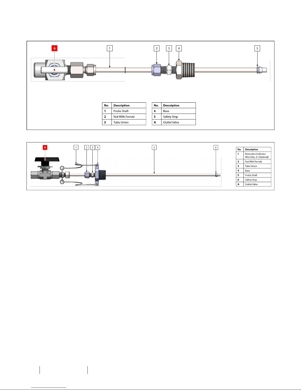
1.4 Equipment Diagrams
Figure 1: Standard AP-3
Figure 2: AP-3 With Optional Retraction Indicator Wires
IOM-009 MODELS: AP-3 and A P-3F REV: D 13839 West Bellfort St reet, Sugar L and, TX 77498 welker. com Servic e Departm ent 281.491.2331
6
Page 7
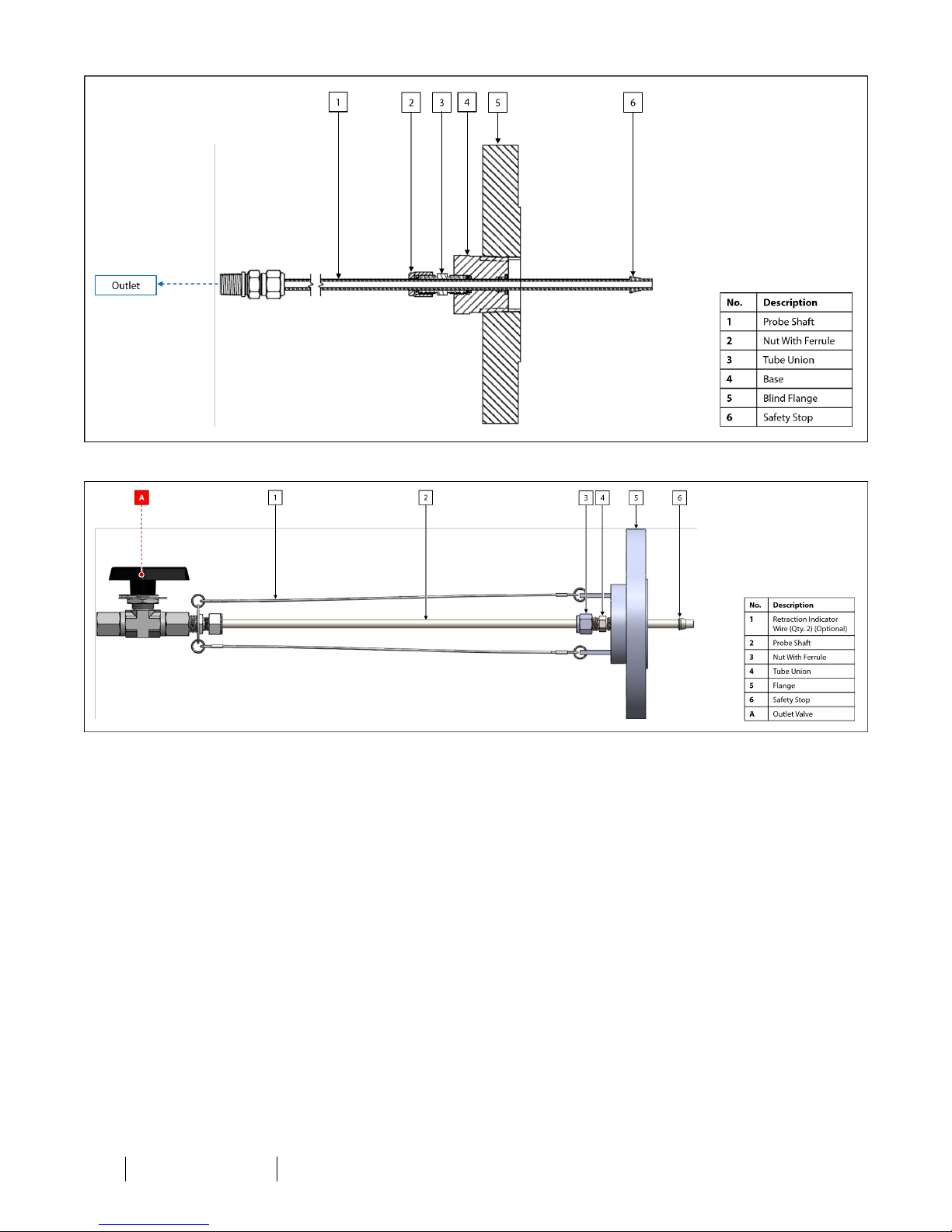
Figure 3: AP-3 With Blind Flange
Figure 4: AP-3F With Optional Retraction Indicator Wires
IOM-009 MODELS: AP-3 and A P-3F REV: D 13839 West Bellfort St reet, Sugar L and, TX 77498 welker. com Servic e Departm ent 281.491.2331
7
Page 8
SECTION 2: INSTALLATION&OPERATION
2.1 Before You Begin
After unpacking the unit, check the equipment for compliance and any damage that may have occurred during shipment.
Immediately contact a Welker representative if you received damaged equipment.
When sealing fittings with PTFE tape, refer to the proper sealing instructions for the brand used.
1. A sample probe is recommended to extract sample from the center one-third (¹∕₃) of the pipeline in a location where
the product is well-mixed and will yield a representative sample.
2. For gas sampling applications, Welker recommends that the unit be installed in the top of the pipe.
3. For liquid sampling applications, Welker recommends that the unit be installed in the side of the pipe.
4. Handle the unit with care. Avoid bending and scratching the probe shaft, which has a polished surface that travels
through seals.
5. Operate the unit slowly and smoothly while inserting and retracting to avoid damaging the unit.
6. Take care not to close the pipeline isolation valve on the probe shaft while the shaft is inserted in the pipeline. This is
the most common cause of damage to Welker probes.
2.2 Preparing the AP-3 for Installation
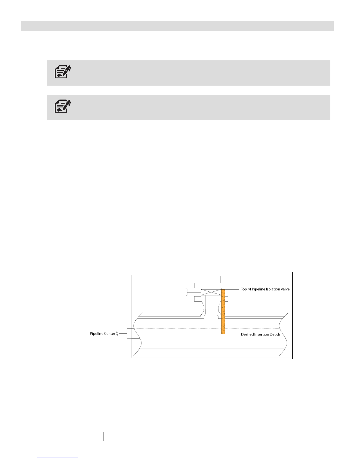
1. Prior to installation, the length the probe shaft will need to travel inside the pipeline must be determined. Measure the
distance the shaft must travel from the top of the pipeline isolation valve to the desired insertion depth (e.g., the center
one-third (¹∕₃) of the pipeline) (Figure 5). This will be the shaft insertion length.
Figure 5: Determining Insertion Depth
2. Pull up on the probe shaft to ensure that it is fully retracted. The safety stop at the tip of the probe shaft will be flush
with the base or flange face.
3.
Beginning at the top edge of the nut, measure along the probe shaft to the desired insertion length (Figure 1, Figure 2,
Figure 3, or Figure 4). Use a felt tip pen to mark this point.
IOM-009 MODELS: AP-3 and A P-3F REV: D 13839 West Bellfort St reet, Sugar L and, TX 77498 welker. com Servic e Departm ent 281.491.2331
8
Page 9

4. Carefully slide the nut and tube union up the probe shaft to the desired insertion length, taking care not to scratch the
probe shaft.
5. Holding the tube union with a wrench, use another wrench to tighten the nut onto the tube union. The ferrule inside
the nut will clasp onto the shaft, locking the tube union in place.
This procedure ensures that the insertion length will be mechanically limited by the tube union assembly.
6. As necessary, cut off excess tubing from the shaft. Beginning at the top edge of the nut, measure approximately two
inches (2") along the shaft. Use a felt tip pen to mark this point.
7. Using tubing cutters, remove the excess tubing at the marked point, and then file and smooth the cut edge of the
probe shaft.
8.
9.
If excess tubing was cut off, return outlet valve A to the top of the probe shaft (Figure 1, Figure 2, Figure 4).
Ensure that outlet valve A is closed (Figure 1, Figure 2, Figure 4).
IOM-009 MODELS: AP-3 and A P-3F REV: D 13839 West Bellfort St reet, Sugar L and, TX 77498 welker. com Servic e Departm ent 281.491.2331
9
Page 10
2.3 Installing the AP-3
Pipeline pressure must be reduced to the maximum allowable insertion/retraction pressure prior to inserting and retracting the
AP-3.
The maximum allowable insertion/retraction pressure varies according to shaft size. Pipeline pressure should be reduced to at or
below:
•
1100 psig (75 barg) for 6 mm tubing.
•
1000 psig (68 barg) for ¼" tubing.
•
500 psig (34 barg) for ³∕₈" tubing.
•
250 psig (17 barg) for ½" tubing.
•
160 psig (11 barg) for ⁵∕₈" tubing.
•
115 psig (7 barg) for ¾" tubing.
•
65 psig (4 barg) for 1" tubing.
1.
If applicable, ensure that outlet valve Ais closed (Figure 1, Figure 2, or Figure 4).
2. Ensure that the probe shaft is retracted.
3. Secure the AP-3 to a full port pipeline isolation valve.
4. Slowly open the pipeline isolation valve. Check for leaks and repair as necessary.
5. To manually insert the AP-3, push down on the top of the probe shaft until the tube union assembly reaches the base or
flange. If manually inserting an AP-3 with blind flange, push down on the top of the probe shaft until the base reaches
the blind flange.
DONOT release the AP-3 until the tube union has been secured to the base or flange.
Push the shaft straight down and do not allow the shaft to bend.
6. Secure the AP-3 in place by tightening the tube union assembly into the base or flange. If manually inserting a AP-3 with
blind flange, secure the AP-3 in place by tightening the base into the blind flange.
7. Install customer-supplied tubing or other fittings to the outlet.
8. Restore the pipeline to full operating pressure.
9.
If applicable, open outlet valve A (Figure 1, Figure 2, or Figure 4).
IOM-009 MODELS: AP-3 and A P-3F REV: D 13839 West Bellfort St reet, Sugar L and, TX 77498 welker. com Servic e Departm ent 281.491.2331
10
Page 11
2.4 Retracting the AP-3
Pipeline pressure must be reduced to the maximum allowable insertion/retraction pressure prior to inserting and retracting the
AP-3.
The maximum allowable insertion/retraction pressure varies according to shaft size. Pipeline pressure should be reduced to at or
below:
•
1100 psig (75 barg) for 6 mm tubing.
•
1000 psig (68 barg) for ¼" tubing.
•
500 psig (34 barg) for ³∕₈" tubing.
•
250 psig (17 barg) for ½" tubing.
•
160 psig (11 barg) for ⁵∕₈" tubing.
•
115 psig (7 barg) for ¾" tubing.
•
65 psig (4 barg) for 1" tubing.
1.
If applicable, close outlet valve A (Figure 1, Figure 2, or Figure 4).
2. Disconnect the customer-supplied tubing or fittings attached to the outlet.
3. Firmly push down on the top of the probe shaft while slowly loosening the tube union assembly from the base or
flange. If retracting an AP-3 with blind flange, firmly push down on the top if the probe shaft while slowly loosening the
base from the blind flange.
Failure to ensure that adequate pressure is applied to the top of the AP-3 prior to retraction could result in unexpected
retraction of the shaft at great speed, which could damage the unit or injure the operator.
4. The AP-3 will begin retracting from the pipeline.
5. Pull up on the probe shaft to ensure that it has been fully retracted.
6. Close the pipeline isolation valve.
7. The AP-3 is now ready to be removed from the pipeline isolation valve for maintenance or to be moved to another
location.
IOM-009 MODELS: AP-3 and A P-3F REV: D 13839 West Bellfort St reet, Sugar L and, TX 77498 welker. com Servic e Departm ent 281.491.2331
11
Page 12
3.1 Before You Begin
SECTION 3: MAINTENANCE
1.
Maintenance is necessary if a leak occurs at the base or flange.
2. Prior to maintenance or disassembly of the unit, it is advisable to have a repair kit available for repairs of the system in
case of unexpected wear or faulty seals.
New seals supplied in spare parts kits should be lightly lubricated before being installed to ease the installation of the seals and
reduce the risk of damage when positioning them on parts. Wipe excess lubricant from the seals, as it may adversely affect
analytical instrument results.
For sample-exposed seals, Welker recommends non-hydrocarbon-based lubricants, such as Krytox®.
For non-sample-exposed seals, Welker recommends either non-hydrocarbon-based lubricants or silicone-based lubricants, such
as Molykote® 111.
After the seals are installed, the outer diameter of shafts and inner diameter of cylinders may be lubricated to allow smooth
transition of parts.
3. All maintenance and cleaning of the unit should be performed on a smooth, clean surface.
4. Welker recommends having the following tools available for maintenance. Please note that the exact tools required may
vary by model.
a. Adjustable Wrench
b. File or Fine Grit Sandpaper
c. Seal Pick
d. Tubing Crimp and Accessories
e. Wire Cutters
3.2 Maintenance
If a leak occurs at the base or flange, the AP-3 requires maintenance.
1.
Prior to performing maintenance, the AP-3 must be removed from the pipeline. See Section 2.4, Retracting the AP-3, for
instructions on retracting the probe shaft and removing the unit from the pipeline.
IOM-009 MODELS: AP-3 and A P-3F REV: D 13839 West Bellfort St reet, Sugar L and, TX 77498 welker. com Servic e Departm ent 281.491.2331
12
Page 13
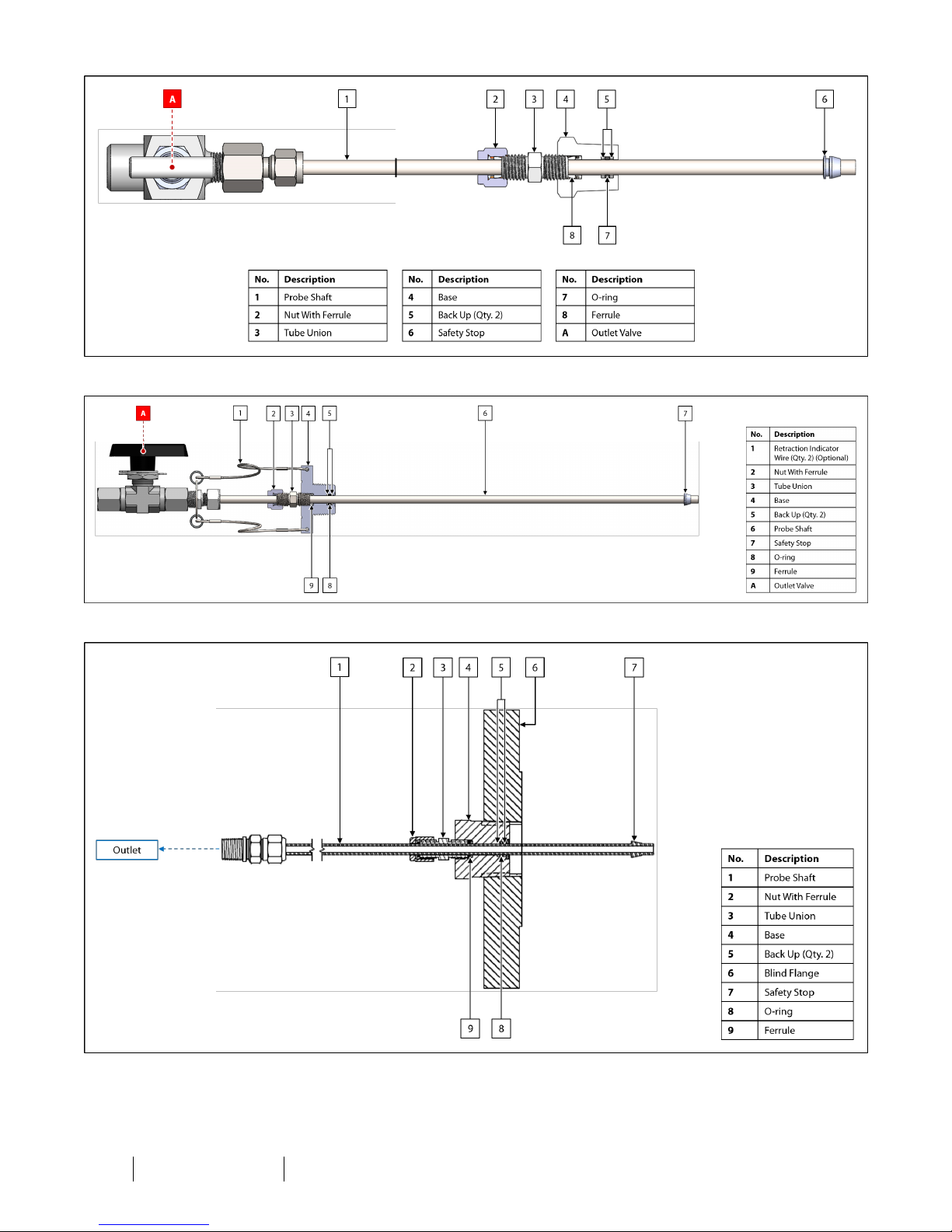
Figure 6: Maintenance Diagram — Standard AP-3
Figure 7: Maintenance Diagram — AP-3 With Optional Retraction Indicator Wires
Figure 8: Maintenance Diagram — AP-3 With Blind Flange
IOM-009 MODELS: AP-3 and A P-3F REV: D 13839 West Bellfort St reet, Sugar L and, TX 77498 welker. com Servic e Departm ent 281.491.2331
13
Page 14
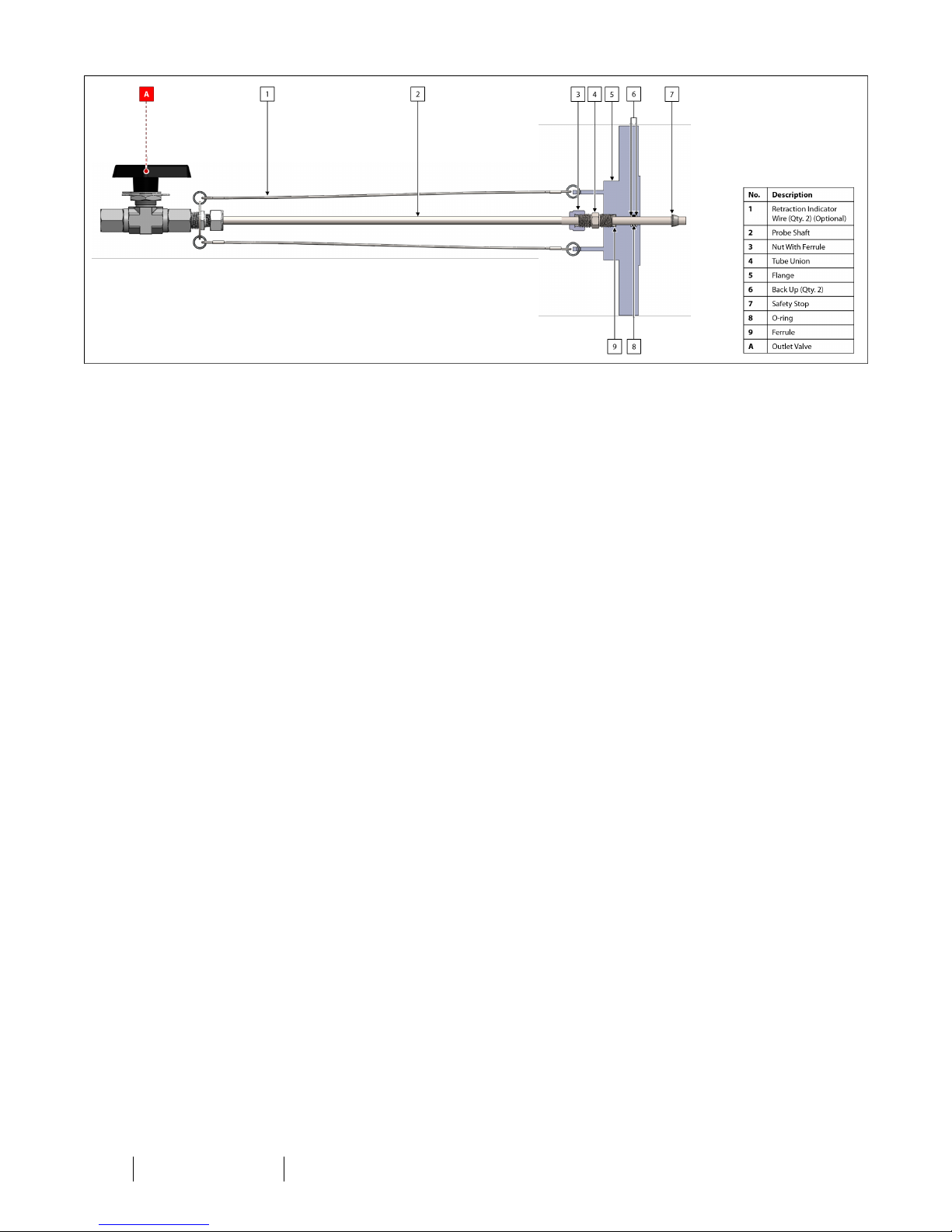
Figure 9: Maintenance Diagram — AP-3F With Optional Retraction Indicator Wires
2.
3.
If applicable, cut the retraction indicator wires and remove them from the AP-3 (Figure 7 or Figure 9).
If applicable, remove outlet valve A from the probe shaft (Figure 6, Figure 7, or Figure 9).
4. Loosen the nut with ferrule.
5. Using tubing cutters, cut the probe shaft below the crimp made by the ferrule inside the nut.
6. File the burr left by the tubing cutters and lightly sand the area. This will allow the probe shaft to slide out of the base or
flange.
7. Slide the probe shaft out through the bottom of the base or flange.
8. Replace the O-ring and back ups in the base or flange.
9. Carefully insert the probe shaft through the bottom of the base or flange.
10. Slide a new ferrule onto the shaft.
11. Return the nut to the shaft.
12.
13.
If applicable, return outlet valve A to the probe shaft (Figure 6, Figure 7, or Figure 9).
If applicable, connect retraction indicator wires from the base or flange to the top of the probe shaft (Figure 7 or Figure
9).
14.
The AP-3 may now be installed to the pipeline. See Section 2.2, Preparing the AP-3 for Installation, and Section 2.3,
Installing the AP-3, for instructions on installing the AP-3 to the pipeline.
IOM-009 MODELS: AP-3 and A P-3F REV: D 13839 West Bellfort St reet, Sugar L and, TX 77498 welker. com Servic e Departm ent 281.491.2331
14
Page 15

APPENDIX A: REFERENCEDORATTACHEDDOCUMENTS
WelkerInstallation, Operation, and Maintenance (IOM) Manuals suggested for use with this unit:
l IOM-105: Welker NV-1 and NV-2 Instrument Valves
Other Installation, Operation, and Maintenance (IOM) Manuals suggested for use with this unit:
l Anderson Greenwood H7/H71 Hand Valves (Welker IOM-V414)
l Apollo Valves 76-100 Series Stainless Steel Ball Valve with Mounting Pad 1/4"-1" (Welker IOM-V141)
l Generant Inc. Forged Needle Valve Series FNV (Welker IOM-V240)
l Parker Hannifin Corporation Ball and Plug Valves (Welker IOM-V213)
l Parker Hannifin Corporation Ball Valves B Series (Welker IOM-V365)
l Swagelok Company Ball Valves 60Series (Welker IOM-V018)
l Swagelok Company Check Valves C, CA, CH, CP, and CPASeries (Welker IOM-V076)
l Swagelok Company Integral-Bonnet Needle Valves O, 1, 18, 20, and 26 Series (Welker IOM-V136)
l Swagelok Company One-Piece Instrumentation Ball Valves 40G Series and 40 Series (Welker IOM-V085)
l Swagelok Company Severe-Service Union-Bonnet Needle Valves N Series and HNSeries (Welker IOM-V347)
l Swagelok Company Trunnion BallValves 83 Series and H83 Series (Welker IOM-V359)
Welker drawings and schematics suggested for use with this unit:
l Assembly Drawing: AD126BU (AP-3 With Retraction Indicator Wires)
l Assembly Drawing: AD126CO (Standard AP-3)
l Assembly Drawing: AD126DR (AP-3F With Retraction Indicator Wires)
l Assembly Drawing: AD126EH (AP-3 Mounted on Blind Flange)
IOM-009 MODELS: AP-3 and A P-3F REV: D 13839 West Bellfort St reet, Sugar L and, TX 77498 welker. com Servic e Departm ent 281.491.2331
15
Page 16

NOTES
____________________________________________________________________________________________________
____________________________________________________________________________________________________
____________________________________________________________________________________________________
____________________________________________________________________________________________________
____________________________________________________________________________________________________
____________________________________________________________________________________________________
____________________________________________________________________________________________________
____________________________________________________________________________________________________
____________________________________________________________________________________________________
____________________________________________________________________________________________________
____________________________________________________________________________________________________
____________________________________________________________________________________________________
____________________________________________________________________________________________________
____________________________________________________________________________________________________
____________________________________________________________________________________________________
____________________________________________________________________________________________________
____________________________________________________________________________________________________
____________________________________________________________________________________________________
____________________________________________________________________________________________________
13839 West Bellfort Street
Sugar Land, TX77498
Phone: 281.491.2331
IOM-009 MODELS: AP-3 and A P-3F REV: D 13839 West Bellfort St reet, Sugar L and, TX 77498 welker. com Servic e Departm ent 281.491.2331
16
welker.com
 Loading...