

Page 1

MedWeld 5000
Integrated Weld Control
Technical Reference Manual
Software #F04100 and #F04300
Revision 02
Modified: 1/31/06
Part No. M-032170
Copyright © 2006, WTC
Page 2

MedWeld 5000 Technical Reference Manual Modified: 1/31/06
M-032170
Page 3

MedWeld 5000 Technical Reference Manual Modified: 1/31/06
Chapter 1 MedWeld 5000 Overview .............................. 1-1
System Description ........................................................................ 1-1
Welding with the MFDC Inverter .................................................. 1-1
Timer Unit ...................................................................................... 1-3
DeviceNet Integration .................................................................... 1-4
Timer Interface to the Inverter ....................................................... 1-4
Timer Unit Output ................................................................................ 1-4
Timer Unit Input ................................................................................... 1-4
Component Descriptions ................................................................ 1-5
Circuit Breaker ............................................................................... 1-5
Isolation Contactor ......................................................................... 1-5
Charging Pack ................................................................................ 1-5
Control Transformer ...................................................................... 1-6
MFDC Inverter .............................................................................. 1-6
Timer Unit ...................................................................................... 1-6
Chapter 2 Installing the MedWeld 5000 ........................ 2-1
Getting Started .................................................................... 2-1
Making the Required Connections ................................................ 2-1
DeviceNet Integration .................................................................... 2-2
Providing MedLAN Connections .................................................. 2-3
MedLAN and DEP-100S Connections .......................................... 2-3
MedLAN Wiring Specifications ........................................................... 2-3
Cable Requirements .............................................................................. 2-3
Cable Routing Requirements ......................................................... 2-4
Setting the timer MedLAN Address .............................................. 2-4
Programming the Timer Unit ......................................................... 2-5
Flexible I/O List ............................................................................. 2-7
Flexible Inputs ...................................................................................... 2-7
DEP-100S Programming Device ................................................... 2-9
Chapter 3 Communications and I/O .............................. 3-1
Local and Safety I/O ........................................................... 3-1
Local Inputs ................................................................................... 3-1
Local Outputs ................................................................................. 3-2
Organization of the DeviceNet I/O ................................................ 3-3
I/O Definitions .................................................................... 3-3
Inputs ............................................................................................. 3-3
Outputs ........................................................................................... 3-8
DeviceNet Bitmap ..............................................................3-11
DEP-100S Abbreviations .................................................. 3-13
Input Abbreviations ..................................................................... 3-13
Output Abbreviations ................................................................... 3-14
Page 4

MedWeld 5000 Technical Reference Manual Modified: 1/31/06
Chapter 4 Weld Schedules ............................................. 4-1
What is a Weld Schedule? ................................................... 4-1
Software Capabilities .......................................................... 4-2
List of Functions ................................................................. 4-3
MedWeld 5000 Funcitons .............................................................. 4-3
Function Descriptions ......................................................... 4-4
Delay Functions ............................................................................. 4-4
Weld Functions .............................................................................. 4-5
Weld Functions Using Automatic Current Compensation ............. 4-7
Weld Functions that Adjust Current .............................................. 4-9
Special Functions ......................................................................... 4-11
Special Function Definitions ....................................................... 4-11
Default Weld Sequence: Robot ......................................... 4-15
Default Weld Sequence: Machine ..................................... 4-15
Chapter 5 Advanced Software Features ........................ 5-1
C-Factor .............................................................................. 5-1
Dynamic Current Windows ................................................. 5-2
AVC Example ................................................................................ 5-2
ACC Firing Mode .......................................................................... 5-3
SPC Indexing Capabilities .................................................. 5-4
SPC Functions ................................................................................ 5-4
SPC setup Parameters .................................................................... 5-5
Retract Features ................................................................... 5-7
Retract Mode Setup Parameter ...................................................... 5-7
Initiation From Retract ................................................................... 5-8
DEP-100S Programming Restrictions ................................ 5-8
Weld/No Weld Status ..................................................................... 5-8
Viewing Weld Data ........................................................................ 5-9
Stepper Function .......................................................................... 5-11
Chapter 6 Setup Parameters .......................................... 6-1
Parameter Descriptions ....................................................... 6-2
Default Settings ..................................................................6-11
Chapter 7 Stepper Data ................................................. 7-1
What is a Stepper? ............................................................... 7-1
Linear Steppers .............................................................................. 7-2
Auxiliary Weld Counters ............................................................... 7-2
Default Linear Stepper Profile ....................................................... 7-3
Page 5

MedWeld 5000 Technical Reference Manual Modified: 1/31/06
Display at the DEP-100S .................................................... 7-4
Chapter 8 Fault Conditions ........................................... 8-1
List of Faults ....................................................................... 8-2
MFDC Fault Status LEDs .............................................................. 8-3
Chapter 9 Hardware Troubleshooting ........................... 9-1
Power Supply ..................................................................... 9-1
Processor ............................................................................. 9-2
Weld Processor ................................................................... 9-3
Solving Typical Problems ................................................... 9-5
Page 6

MedWeld 5000 Technical Reference Manual Modified: 1/31/06
Page 7

MedWeld 5000 Technical Reference Guide Modified: 1/31/06 vii
M-032170
Getting Started
If You Need Help . . .
Welding Technology
Corp. (WTC)
WTC is committed to quality products, service and support. Our service
department maintains an assistance hotline to assist with application or
troubleshooting during normal business hours.
By Phone or Fax: To arrange for field service, call one of these numbers:
Industrial Technical Service (ITS) Voice: (248) 477-3900
Fax: (248) 477-8897
The ITS telephone number offers 24-hour service, seven days a week.
Before calling, make a note of any fault conditions, applicable software
and hardware revision numbers. Record the part number of the
enclosure (on the serial tag on the inside or front door of the enclosure).
Also note the sequence of events leading to the problem, and the
drawing numbers of the schematics you received with the enclosure.For
your convenience, fill out the “Problem Report Form” on page -xv.
By E-mail: When an immediate response is not critical, contact WTC at the
following e-mail addresses:
WTC’s technical support will respond within 24 hours, Monday through
Friday, to your e-mail requests. Please include your name, company
name, location, product part and serial number and a description of the
problem with your request. Be sure to indicate how you want us to
respond, and include applicable phone and fax numbers with your email address.
On the Web: Visit our Web site at: www.weldtechcorp.com.
Sales/Marketing Comments
Technical Support
Page 8
Getting Started
viii Modified: 1/31/06 MedWeld 5000 Technical Reference Guide
M-032170
Symbols Used in This Manual
Danger! and WARNING! messages indicate high-voltage hazards in
weld controls, SCRs, MFDC inverters and weld monitoring equipment.
Danger! This symbol will be used wherever failure
to observe safety measures may result in
death, severe bodily injury or serious
damage to property.
WA RN IN G !
This symbol will be used wherever insufficient
or lacking compliance with instructions may
result in personal injury.
Caution: and NOTE: messages indicate the following:
Caution:
This symbol denotes when insufficient or lacking
compliance with the instructions may damage
equipment or files.
NOTE: This convention informs the user about special features, or where to find
more information.
Page 9
Getting Started
MedWeld 5000 Technical Reference Guide Modified: 1/31/06 ix
M-032170
Revision History
Safety Dangers
Danger! FAILURE TO OBSERVE SAFETY MEASURES
MAY RESULT IN DEATH, SEVERE BODILY
INJURY OR SERIOUS DAMAGE TO PROPERTY.
Danger!
LETHAL voltages are present when applying
power to the weld control. Exposure to high
voltage WILL CAUSE SEVERE ELECTRICAL
BURNS, INTERNAL INJURIES and/or DEATH.
Refer all necessary service on this machine
ONLY to qualified maintenance personnel.
Danger!
NEVER drill into the control cabinet without
properly protecting internal components from
metal debris and removing power. Failure to
observe this requirement may cause a
potential EXPLOSION HAZARD.
Revision Release Date Comments
1 01/31/05 Initial release of manual.
2 09/07/05 Added F04300 MFDC software parameters.
Page 10
Getting Started
x Modified: 1/31/06 MedWeld 5000 Technical Reference Guide
M-032170
Danger!
Always ensure proper flow rate, temperature
and chemistry of cooling water. Obstructed or
insufficient flow of cooling water may damage
welding transformers, SCRs or MFDC inverters.
Refer to “Cooling Water Requirements” on page
-xii for more details.
Danger!
NEVER remove circuit boards with
110 VAC (or higher voltage) power applied. Be
certain to REMOVE POWER BEFORE servicing,
installing or removing circuit boards.
Caution:
When lifting any weight over 20 kg (~45 lb.),
use either a two-man lift or an assisted lift.
How to Use this Manual
This manual is designed as a reference guide. Use it as you would a
dictionary. See the Table of Contents to locate the instructions or
information you require. For additional details, you are referred to the
appropriate sections and page numbers.
The Table of Contents lists each section and subsection. In these
sections, descriptive subheadings indicate the information provided.
Simply flip to the page number and subheading indicated.
Detailed procedures describe the steps required to perform each
programming task. Other descriptions explain the procedures for
installation, initialization and troubleshooting, along with explanations
of the hardware and each weld function.
Page 11

Getting Started
MedWeld 5000 Technical Reference Guide Modified: 1/31/06 xi
M-032170
Software Updates
WTC reserves the right to make substitutions or changes as required to
the hardware or software described in this manual.
This manual may be periodically updated to reflect software changes
that will affect operation of the equipment described. Request copies of
the latest updates by completing the “Comments for Feedback Form” on
page -xvii, or by visiting WTC’s Web site: www.weldtechcorp.com.
Page 12

Getting Started
xii Modified: 1/31/06 MedWeld 5000 Technical Reference Guide
M-032170
Cooling Water Requirements
Specifications on
the Web
The specifications for cooling water are subject to change. For the latest
specifications, go to the WTC Web site:
http://www.weldtechcorp.com/documentation/index.html.
Working with Static-Sensitive Devices
ESD Costs! Electrostatic discharge (ESD) can ignite flammable materials and
damage electronic components. Static electricity can attract
contaminants in clean environments or cause products to stick together.
Other costs of ESD-damaged electronic devices are in their replacement
and production down time. Associated costs of repair and rework,
shipping, labor and overhead can be significant. Reducing losses to ESD
and static electricity is an ABSOLUTE NECESSITY.
Observe the following warnings AT ALL TIMES:
Danger! NEVER use the personnel grounding system
described below when working with
voltages above 220 VAC.
Personnel
Grounding
Before touching any Electrostatic Discharge Sensitive (ESDS) devices
or circuit boards, put on and wear an Electrostatic Discharge (ESD)
wrist strap. Ground this strap through a one megohm (1 MΩ) resistor.
Handling or Moving
ESDS Devices
Handle all circuit boards by their edges ONLY. NEVER touch the traces
or edge pad connectors.
Transport, store and ship ESDS devices and circuit boards in a static
shielding container. An acceptable container is either a static shielding
bag or a static shielding tote. To be effective, either type of container
MUST be closed.
NOTE: Use ONLY static-shielding containers for transporting ESDS devices or
circuit boards.
Page 13

Getting Started
MedWeld 5000 Technical Reference Guide Modified: 1/31/06 xiii
M-032170
Workstation
Requirements
If diagnostics are required, move the circuit board to an approved ESD
workstation. A static-safe workstation must include a grounded ESD
mat, wrist strap and cord. The measured static voltage at a workstation
MUST NOT exceed 50 volts.
Contact
Information
For detailed information about ESD precautions, contact
Copyright
WTC software and publications are copyrighted and all rights are
reserved by WTC. Distribution and sale of software is intended for the
use of the original purchaser, and only for use on a single machine.
Copying, duplicating, selling or otherwise distributing this software is a
violation of law.
WTC specifically does not authorize duplication of the software stored
in the EEPROM, distribution media (magnetic or CD-ROM) or in print
form, without prior written authorization and payment of royalty fees.
Patents
This product contains intellectual property owned or licensed by WTC,
excluding (but not limited to) one or more of the following U. S.
patents:
Other patents, U. S. or foreign, may be issued or pending.
The software and documentation associated with this product are
protected by copyrights owned by WTC. Trademarks have been adopted
and used on all or part of this product.
ESD Association
Voi ce : 315–339–6937
Fax: 315–339–6793
e-mail: [email protected]
4,388,515
4,493,040
4,804,819
4,973,419
5,386,096
5,483,035
4,399,511
4,513,363
4,831,229
4,945,201
5,424,506
5,589,088
4,459,456
4,516,008
4,849,873
5,128,507
5,440,092
5,667,704
4,459,457
4,721,840
4,851,635
5,276,308
5,449,887
5,757,176
4,463,244
4,733,045
4,885,451
5,347,105
5,471,028
5,793,243
4,973,815
6,130,396
6,215,086
6,225,590
6,342,686
6,359,566
Page 14

Getting Started
xiv Modified: 1/31/06 MedWeld 5000 Technical Reference Guide
M-032170
This page is intentionally left blank.
Page 15

Getting Started
MedWeld 5000 Technical Reference Guide Modified: 1/31/06 xv
M-032170
Problem Report Form
Plant Name and Location:
Phone:
Your Name: Date:
Time:
Program # (Timer power-up message): – – / /
Part #:
Fault code display. When a fault or error occurs, the Product ### displays
a status code. Indicate each code that is displayed:
Description of the problem:
Sequence of events leading to the problem:
Drawing number(s) of schematic(s) shipped with the Product ###:
Page 16

Getting Started
xvi Modified: 1/31/06 MedWeld 5000 Technical Reference Guide
M-032170
This page is intentionally left blank.
Page 17

Getting Started
MedWeld 5000 Technical Reference Guide Modified: 1/31/06 xvii
M-032170
Your Feedback Welcome Here!
We welcome your feedback on the accuracy and usefulness of this
manual. Our Training and Documentation staff will review your
comments and implement the required corrections in future updates.
For specific comments, fill in the Comments for Feedback form below.
Fax it at (248) 477-8897.
Comments for
Feedback Form
Your Name: Date: Time:
Company Name: Phone:
Company Address:
City:
State: ZIP:
Program/Revision #:
# of Manuals at your site:
Document Number/Name:
Your comments:
Page 18

Getting Started
xviii Modified: 1/31/06 MedWeld 5000 Technical Reference Guide
M-032170
This page is intentionally left blank.
Page 19

MedWeld 5000 Technical Reference Manual 1 - 1
M-032170
MedWeld 5000 Overview 1
System Description The MedWeld 5000 provides firing signals to the MFDC inverter, in
turn, the MFDC provides DC welding current.
This modular design allows use in a number of applications and
provides two forms of integration:
• Discrete interface (DIO). The weld control can exchange I/O with a
machine, robot or portable gun controller. The weld control
communicates using inputs from the automation and outputs to the
automation.
• A DeviceNet ™ interface. This open communications standard
provides a low-cost communications link with I/O messaging
between the weld control and tool.
These advanced integration options provide added flexibility to the
WTC design, which provides full-function and programming
capabilities.
The control compensates for changes in the welding environment by
monitoring the voltage and increasing the current as required to ensure
consistent welds. The primary current (I) changes as the voltage
fluctuates (for example, if the weld energy (E) drops, the timer firing
phase shifts forward (to increase I) until E stabilizes.).
You program a weld function specifying current in two ways:
• To use either Automatic Voltage Compensation (to maintain a
desired primary voltage) or
• Automatic Current Compensation (to maintain constant secondary
current).
The MedWeld 5000 can perform the weld, delay, slope, pulsation or
timing functions required by your application. Other functions allow
you to control outputs and monitor the status of inputs.
Welding with the
MFDC Inverter
The MFDC Inverter replaces the silicon-controlled rectifiers (SCR
packs) used to provide the high-voltage welding current to the welding
transformer.
The inverter and timer unit replace both the firing card and the thyristors
used in conventional, single-phase welding. The “intelligent” timer or
regulator/driver allows the inverter to be driven by firing signals from
Page 20

MedWeld 5000 Overview
1 - 2 MedWeld 5000 Technical Reference Manual
M-032170
the timer unit. It also provides fault detection. Finally, mid-frequency
conversion reduces the size of the welding transformer and the power
line demand required.
• SPC data (Group, bin and part number)
This data can be reviewed this data with a programming device
(such as the WTC DEP-100S Hand-Held Terminal), or use it for
data analysis by programs such as WTC’s WebVIEW.
• Sequence number executed
• Transformer turns ratio
• Minimum, average and maximum DC bus voltage
• Minimum, average and maximum secondary current
•C-factor
• Average on-time
• Number of cycles in the last weld
• Line cycle or milisecond timing
• Stepper data and
• Desired constant current.
The MFDC is different from “traditional” single-phase welding and
high-frequency DC welding in the following ways:
• There is essentially no power factor or impedance in highfrequency welding that corresponds to the power factor issues of
AC welding. The power factor is high and constant, and the welder
transformer secondary circuit is direct current (DC).
• The welding transformer depends on the applied voltage and circuit
resistance. It is generally independent of the magnetic effects of the
secondary circuit. (Magnetic material in the secondary is not a
consideration.)
• Given a constant applied voltage, the weld current depends
primarily on the resistance of the weld itself. (Welds with different
resistances will result in different weld current.)
Page 21

MedWeld 5000 Overview
MedWeld 5000 Technical Reference Manual 1 - 3
M-032170
Timer Unit The timer unit sends a gating signal to the inverter, as required by the
weld schedule. The timer unit will tell the inverter when to pull in the
main power isolator, allowing the inverter to provide welding current.
The timer unit performs all the weld timing functions required to
execute a weld schedule:
• Checks input signals (provided through DeviceNet) and reacts to
them accordingly.
• Operates the output signals based on the weld schedule.
• Sends the gating signals to the inverter as required by the weld
schedule.
• Adjusts the firing signal, based on the control’s firing mode, to
provide a constant supply despite changes in the welding
environment.
• LEDs on the timer unit module indicate control status. These
indicators are described below:
If the LEDs do not turn on during the weld schedule, the timer unit may
be faulty, or the control may be sequencing in No Weld mode.
PWR
This LED lights to indicate that power is being supplied to the
timer unit and it is functioning normally.
RUN
These LEDs light to indicate that the timer unit card has sent
the logic level gating signal to the inverter. These LEDs are
normally off. They should only turn on when current is
provided by the weld schedule.
SEQ
These 2 LEDs light to indicate that communication is
occurring on the MedLAN channel.
NS
These LEDs light to indicate that communication is taking
place between the data entry panel (DEP) and the timer unit
card.
EN
This LED lights when the control is ready to weld. This means
that the control will provide current under these conditions:
• No faults exist
• The Control Stop Input is not active (off is active)
• The control is in Weld Mode
• The WCU is synchronized with the welding bus and
• The Inverter is ready to weld (the IRTW signal is high).
Page 22
MedWeld 5000 Overview
1 - 4 MedWeld 5000 Technical Reference Manual
M-032170
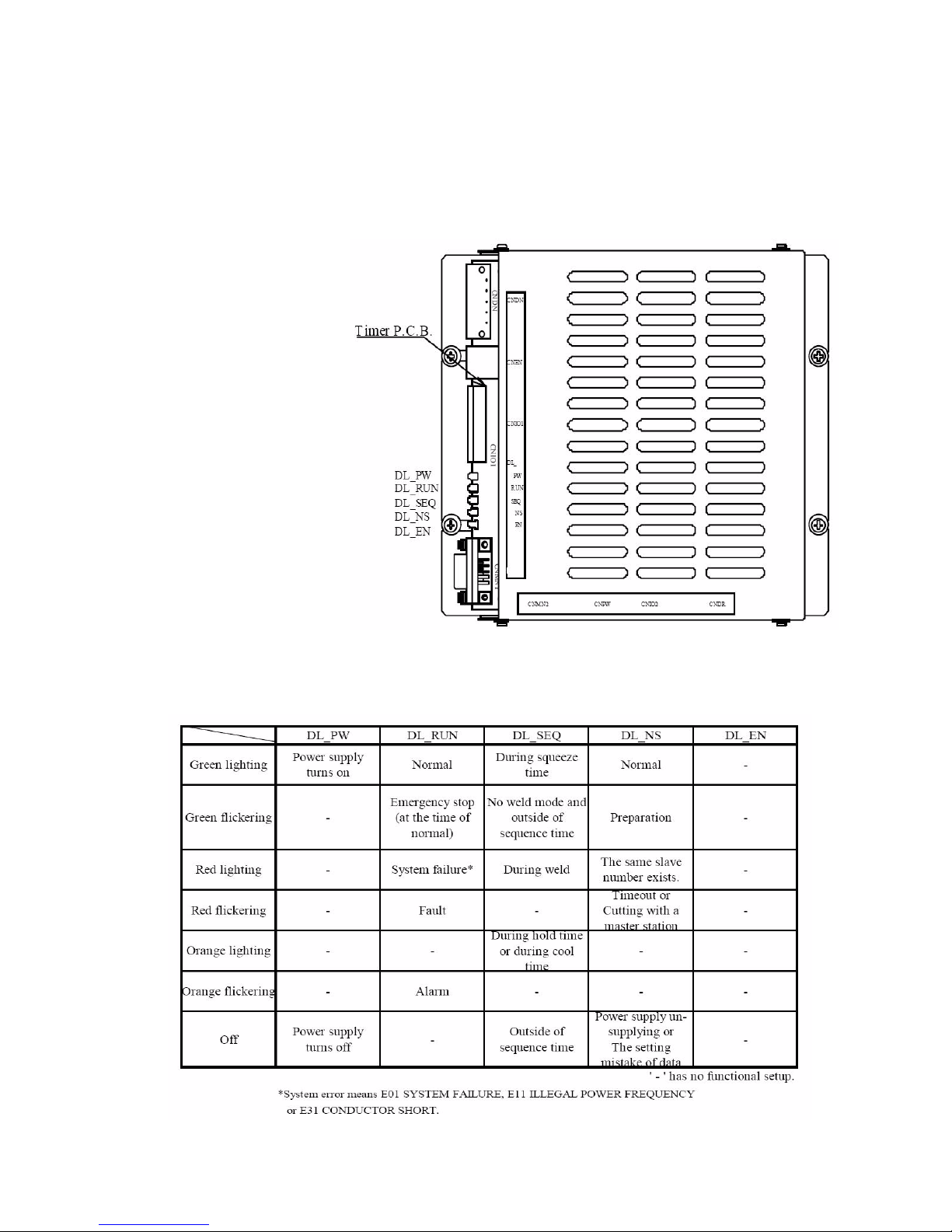
Timer LED Indicators The timer unit in your MedWeld 5000 weld control (shown below) has
indicator lights that show the current status of the weld timer. The
diagrams below show the location of the status lights and what
conditions cause the status lights to turn on.
Timer Status Lights The light color, flicker and location indicate the current status of the
weld timer.
Page 23

MedWeld 5000 Overview
MedWeld 5000 Technical Reference Manual 1 - 5
M-032170
DeviceNet Integration This integration scheme supports a network of DeviceNet devices,
allowing for rapid communications between industrial devices.
The DeviceNet communications protocol is an open network standard,
maintained by the Open DeviceNet Vendor Association (ODVA). The
DeviceNet protocol allows for peer-to-peer data (where any product can
produce or consume messages and the DeviceNet product can function
as Client, Server or both. The network can have up to 64 node
addresses, and each node supports an infinite number of I/O.
NOTE: For more information on DeviceNet, contact your WTC representative.
Timer Interface to the
Inverter
The interface between the timer unit and the MFDC inverter allows the
MedWeld 5000 to specify the amount of current to the work piece, allow
the inverter to alert the timer of fault conditions it detects during the
weld, and provides weld data to the timer, which is then displayed on the
DEP.
The inverter responds to the gating signals from the timer unit. The
timer unit tells the inverter when to pull in the main isolation contactor
and receives the signal from the inverter when the inverter is ready to
weld.
Timer Unit Output
The timer unit activates the Turn On The Isolation Contactor output to
the inverter when it executes Function #88 in the weld sequence. This
output is NOT directly wired to the isolation contactor: It sends a signal
to the inverter that the contactor should be pulled in. (The inverter’s
regulator board receives the signal. The regulator board is wired to the
isolation contactor.)
Timer Unit Input
The timer unit receives the isolation contactor input directly from the
isolation contactor. This input indicates the status of the contactor
(pulled in or dropped out).
The timer unit also receives a Ready to Weld signal from the inverter
(IRTW). This indicates when the inverter is capable of providing weld
current:
• The inverter thermal switches indicate that cooling water is present
• The isolation contactor can be pulled in
• The inverter capacitors are ready for charging (to provide DC bus
voltage).
Page 24

MedWeld 5000 Overview
1 - 6 MedWeld 5000 Technical Reference Manual
M-032170
Component
Descriptions
The MedWeld 5000 control consists of the following components:
• Timer unit
• Circuit breaker,
• Isolation contactor,
• Charging pack,
• Control transformer and
•MFDC Inverter.
Circuit Breaker The control circuit breaker serves to remove power to the welding
control and all of its internal components. Incoming power enters the
control enclosure through the access plates at the top right of the
cabinet. With the weld control connected to the weld bus and the circuit
breaker in the ON position, supply voltage is applied to the input of the
charging pack as 1L1, 1L2 and 1L3.
The size of the circuit will vary, depending on the size of the inverter
and the application the inverter is to be used in. Cabling into the
inverter should be sized to the current rating of the circuit breaker.
Danger! Lethal voltage may be present in the
inverter for several minutes after the power
source has been removed at the circuit breaker.
Power MUST be removed from the DC bus before assuming that it is
safe to service or maintain the weld enclosure.
Isolation Contactor The isolation contactor is provided electrically after the inverter. This
contactor removes power from the weld transformer using the
ISOLATION CONTACTOR output at the SLC output module.
Charging Pack The charging pack controls when power will be provided to the
inverter's charging capacitors. The charging pack differs between the
different models of inverters. (Refer to the drawings provided with your
control for more complete information.) Once the charging pack
activated, it remains activated until either an inverter fault is generated,
the charge request signal is deactivated.
If the inverter has discharged just before it is requested to close, the
inverter may delay activating the charging pack for up to 20 seconds.
Page 25

MedWeld 5000 Overview
MedWeld 5000 Technical Reference Manual 1 - 7
M-032170
Control Transformer The control transformer receives the supply voltage (480, 415 or 380
VAC at 50 Hz or 60 Hz) from the circuit breaker. It reduces the supply
voltage to the level required for other devices. It has step-down taps for
• 120 VAC outputs and
• Low-voltage (24 VAC) “clean” power to the electronics power
input of the inverter regulator board.
MFDC Inverter The MFDC inverter assembly consists of a regulator board, the charging
pack, discharge resistors, capacitors and IGBTs (insulated gate bipolar
transistors). The IGBTs control the time that current is allowed to pass
to the welding transformer.
The regulator board receives the gating signal from the timer unit and
translates the signal into target flux or current (depending on firing
mode). The regulator gates the IGBTs and monitors to obtain the target.
The charging pack is described above. The discharge resistors discharge
the capacitors.
• The capacitors smooth the VDC bus and provide energy during the
weld.
• The IGBTs are electronic switches that control when power is
supplied to the welding transformer.
• Inverters have at least one thermal switch that monitors
temperature. The inverter will stop gating if a thermal switch is
tripped.
• The inverter provides the outputs to the welding transformer at H1
and H2.
Timer Unit When the MedWeld 5000 timer unit receives a START WELD
command, the timer unit starts executing the selected weld sequence.
When the DC bus voltage stabilizes, the inverter is ready to weld. The
inverter activates the IRTW signal, and the timer unit is capable of
sending gating signals to the inverter. The inverter performs the power
conversion to provide DC current to the welding transformer.
At the end of the weld sequence, the timer unit drops out the isolation
contactor for the weld transformer.
NOTE: If the weld control provides the weld transformer isolation contactor, the
inverter remains activated and is de-activated only by inverter fault
conditions or power-down of the weld control. Refer to the drawings
provided with your system for more information.
The timer unit indicates any fault conditions detected at the inverter,
either at the data entry panel, or at another MedLAN device connected
to the timer unit. (This can be the WebVIEW.)
Page 26

MedWeld 5000 Overview
1 - 8 MedWeld 5000 Technical Reference Manual
M-032170
Faults generated in this system are of two types:
• Faults generated by the timer unit, and
• Faults generated by the MFDC inverter.
Inverter faults will de-energize the charging pack. Any fault shown on
the DEP or any MedLAN device will inhibit the firing signal to the
inverter (but does not de-energize the charging pack).
Page 27

MedWeld 5000 Technical Reference Manual 2 - 1
M-032170
Installing the MedWeld 5000 2
To install the MedWeld 5000, you must provide the required DeviceNet
communications, configure the unit for the MedLAN network, set the
network address and program the timer unit to meet your application
requirements.
These steps are described in the sections that follow.
Getting Started
Making the Required
Connections
To install the MedWeld 5000, follow these steps:
1. Make certain the circuit breaker handle on the enclosure is in the
OFF (down) position before attempting to open the door.
WARNING! WARNING! The cabinet door is interlocked with
the circuit breaker to prevent opening the door
while power is applied. DO NOT attempt to force
open the door. Damage to the cabinet may
result. NEVER attempt to defeat the interlock.
2. Inspect the inside of the enclosure for any damage caused in
shipping. Check for any parts which may have come loose in
shipping, any packing materials or loose connections.
3. Place the enclosure in the desired location. Secure it with the
mounting tabs and holes provided. The cabinet is designed to be
mounted using all four of the mounting tabs.
Page 28

Installing the MedWeld 5000
2 - 2 MedWeld 5000 Technical Reference Manual
M-032170
WARNING! WTC does NOT recommend drilling additional
holes in the cabinet for additional brackets. If
additional holes are required, make certain all
components are covered to protect them from
metal shavings. Metal debris (from drilling into
the cabinet) can cause catastrophic failure. The
WTC warranty does NOT cover damage caused
by metal debris.
NOTE: Removable plates may be provided to connect cooling water, weld bus
voltage, the welding transformer and to allow for wiring into the I/O.
4. With the welding bus power off, connect the power cables from the
welding bus to the top of the circuit breaker.
5. Provide the connection to the weld transformer. (Refer to the decal
affixed on the enclosure for assistance in connecting the welding
transformer.)
6. Provide the MedLAN connections through the access plate at the
top of the enclosure (if a MedLAN connection is desired or
required). Provide the I/O connections based on the control’s
integration scheme.
DeviceNet Integration DeviceNet communications protocol is an open network standard,
maintained by the Open DeviceNet Vendor Association (ODVA). This
protocol allows for peer-to-peer data (where any product can produce or
consume messages and the DeviceNet product can function as Client,
Server or both). The network can have up to 64 node addresses. Each
node supports an infinite number of I/O.
7. Finally, make the connection to the DeviceNet drop line at the
terminal block plug provided on the DeviceNet module. To do this,
match the wire insulation wire colors to the colors shown on the
terminal block label. Also, the trunk lines at both ends of your
DeviceNet system must be terminated with 121 Ohms, 1%, 1/4W
terminating resistors.
NOTE: The MedWeld 5000 is designed to use either DeviceNet or Discrete I/O.
When configuring the I/O for your application, be certain that the
DeviceNet and Discrete I/O do not conflict with each other. Conflicting
I/O will not allow the weld control to fire. An example of conflicting
Page 29

Installing the MedWeld 5000
MedWeld 5000 Technical Reference Manual 2 - 3
M-032170
I/O would be having different I/O in both the discrete I/O map and the
Fieldbus I/O map. If the operator has programmed matching I/O maps
for discrete and Fieldbus I/O, the Fieldbus I/O takes precedance.
Caution:
DO NOT wire into the network while the network
power supply is turned on. This may short the network
or disrupt communications.
Providing MedLAN
Connections
MedLAN (WTC’s Local Area Network) is a proprietary
communications protocol. It defines how devices on the network
communicate with each other.
NOTE: The MedLAN address identifies each weld control’s location on the
network; therefore each weld control’s address must be programmed
BEFORE communication over the MedLAN channel is possible.
Networking takes place over the MedLAN channel. Use a WTC data
entry device DEP-100, or WebView for network communications or to
program a single weld control.
However, for the MedLAN network, you MUST use a DEP-100S
Programming Device to program the MedLAN address for each control
on the network through the programming port.
NOTE: In some configurations, a connector is provided on the door of the
enclosure for convenience in connecting the DEP-100. This port is
internally wired to the timer unit card.
This must be done before you can use MedLAN. If you do not program
a MedLAN address, communication errors may result.
MedLAN and DEP-
100S Connections
The network connection requires a WTC Network Power Pack for
power to the DEP-100S programming device.
MedLAN Wiring Specifications
The MedLAN interface is an optically-isolated RS–485 connection. The
baud rate of this connection is 9,600.
Cable Requirements
WTC recommends using the Belden 9463 cable or equivalent. The
following tables list the cable pinouts.
Page 30
Installing the MedWeld 5000
2 - 4 MedWeld 5000 Technical Reference Manual
M-032170
Caution:
Remove power BEFORE attempting to connect or
disconnect cabling. Exercise care when making the
MedLAN cable connections. If the MedLAN cable
should become connected to the MDP1 and MDP2
power connections, serious damage to communication
components WILL occur.
WARNING! NEVER connect any of the communication ports
to the MDP- power wires. Damage to the ports or
other internal components may result.
Cable Routing
Requirements
Wire the MedLAN network ONLY in a “daisy-chain” method. NEVER
use “stub” wiring.
The maximum total length of the MedLAN network cable is 3,000 feet.
Up to 30 weld controls may be connected to a single MedLAN network.
A maximum of one DEP-100S, may be connected to a single MedLAN
network.
WARNING! Be certain to cover all components to protect
them from metal shavings. Metal debris (from
drilling into the cabinet) can cause catastrophic
failure. The WTC warranty does NOT cover
damage caused by metal debris.
Physically separate the MedLAN cable from wiring greater than 50
volts. If the MedLAN cable must cross this wiring, it must do so at a 90°
angle.
Setting the timer
MedLAN Address
The MedWeld 5000 uses MedLAN (WTC’s proprietary Local Area
Network) to create a communications network between devices. After
configuring each control, establishing the MedLAN connection and
powering it up, you must set the MedLAN address for each device
before it can respond to the network.
Page 31
Installing the MedWeld 5000
MedWeld 5000 Technical Reference Manual 2 - 5
M-032170
Caution:
The MedWeld 5000 address is the same as the
DeviceNet node address. If the port address is changed
in the network settings, DeviceNet node address will be
changed to match the port address and vise versa.
Use the WTC DEP-100S to program the MedLAN address for each
individual weld control, through the top (DEP) port of the timer unit.
NOTE: The steps required to set the address are listed below. Refer to the
manual provided with the DEP-100S programming device for more
information on operation.
To set the addresses for each weld control, follow this procedure:
1. Plug the DEP-100S into the DEP port on the timer unit (or the DEP
port on the enclosure door, if provided).
2. Press the key labeled PROGRAM MODE on the DEP-100S.
3. Press F5 on the DEP-100S (for additional functions).
4. Press F4 to select network addressing (NETWORK ADDR).
Press the F1 key to select the port # (MedLAN address).
With the numeric keys, enter an address (“port”) number (00–29).
Press ENTER to tell the DEP-100S you have completed your selection.
Press the F3 (download) to send the new MedLAN address to the
device. (A message that the download was completed will appear
briefly.)
Unplug the DEP-100S and move to the next control. Follow this
procedure for every control in the network.
Caution:
Make certain that each device has a unique address.
Duplicate addresses may cause the network to lock up.
Programming the
Timer Unit
Each timer unit provides flexible I/O for defining weld schedules. It also
lets you configure the device to meet your application requirements by
programming setup parameters. The control provides programmable
steppers to compensate for lost current density over the life of the
electrodes.
Page 32

Installing the MedWeld 5000
2 - 6 MedWeld 5000 Technical Reference Manual
M-032170
All of these features are programmable from several different
programming devices:
• Plug the WTC DEP-100S programming device into the connector
on the enclosure door or on the timer unit module.
• The robot teach pendant.
The flexible I/O allows the operator the ability to program the I/O map
for discrete I/O control or the fieldbus I/O for DeviceNet. Flexible I/O
allows an operator to designate which I/O point is used for a particular
function. For example, if the operator wants to use the input Weld
Initiate, he has the option of putting Weld Initiate on any of the 0-15
inputs he chooses. The flexible I/O should not be in conflict with
another I/O point, this may inhibit the weld control from firing. An
example of conflicting I/O would be having the discrete I/O map and the
FieldBus I/O programmed differently. If the I/O maps for the discrete I/
O and the I/O for the Fieldbus map are identical, the Fieldbus I/O will
take precedance.
Page 33

Installing the MedWeld 5000
MedWeld 5000 Technical Reference Manual 2 - 7
M-032170
Flexible I/O List for
Software #F04100
The following is a list of the flexible inputs and outputs available to
operators. The following I/O can be placed in any order, however, if the
software finds a duplicate in the list, the first duplicate in the list will be
changed to NONE.
Flexible Inputs (Software #F04100)
- NONE
- BINARY SELECT 1
- BINARY SELECT 2
- BINARY SELECT 4
- BINARY SELECT 8
- BINARY SELECT 16
- BINARY SELECT 32
- WELD INITIATE
- WELD / NO WELD
- ISOLATION CONTACTOR SAVER
- FAULT RESET
- WELD PROCEED
- STEPPER RESET
- STEPPER RESET GROUP 1
- STEPPER RESET GROUP 2
-TIP DRESS
- STEPPER AUX WELD CNTR RESET
- APP ERR ACKNOWLEDGE
- CONTROL STOP
- PRESSURE SWITCH
- AUXILLARY COOLING
- PROGRAM DISPLAY SECURITY
- HEAT DISPLAY SECURITY
- USER INPUT 1
- USER INPUT 2
- USER INPUT 3
- USER INPUT 4
- USER INPUT 5
- USER INPUT 6
Page 34

Installing the MedWeld 5000
2 - 8 MedWeld 5000 Technical Reference Manual
M-032170
Flexible Outputs (Software #F04100)
- NONE
- VALVE 1
- VALVE 2
- VALVE 3
- VALVE 4
- VALVE 5
- VALVE 6
- NO FAULT
- NO ALERT
- FAULT
- ALERT
- WELD MODE ON
- NO WELD
- WELD IN PROGRESS
- WELD COMPLETE
- READY TO WELD
- STEPPERS ARE RESET
- STEPPERS ARE RESET GROUP 1
- STEPPERS ARE RESET GROUP 2
- END OF STEPPER
- END OF STEPPER GROUP 1
- END OF STEPPER GROUP 2
- STEPPER APPROCHING MAX
- STPR APPROCHING MAX GROUP 1
- STPR APPROCHING MAX GROUP 2
- TIP CHANGE REQUIRED
- TIP DRESS REQUEST
- STEPPER AUX COUNTER AT MAX
- APP ERROR AVAILABLE
- APP ERROR BIT 1
- APP ERROR BIT 2
- APP ERROR BIT 4
- APP ERROR BIT 8
- APP ERROR BIT 16
- PRESSURE SELECT 1
- PRESSURE SELECT 2
- PRESSURE SELECT 3
- PRESSURE SELECT 4
- USER OUTPUT 1
- USER OUTPUT 2
- USER OUTPUT 3
- USER OUTPUT 4
- USER OUTPUT 5
- USER OUTPUT 6
Page 35

Installing the MedWeld 5000
MedWeld 5000 Technical Reference Manual 2 - 9
M-032170
Flexible I/O List for
Software #F04300
The following is a list of the flexible inputs and outputs available to
operators. The following I/O can be placed in any order, however, if the
software finds a duplicate in the list, the first duplicate in the list will be
changed to NONE.
Flexible Inputs (Software #F04300)
- NONE
- BINARY SELECT 1
- BINARY SELECT 2
- BINARY SELECT 4
- BINARY SELECT 8
- BINARY SELECT 16
- BINARY SELECT 32
- WELD INITIATE
- WELD / NO WELD
- ISOLATION CONTACTOR SAVER
- FAULT RESET
- WELD PROCEED
- STEPPER RESET
- STEPPER RESET GROUP 1
- STEPPER RESET GROUP 2
-TIP DRESS
- STEPPER AUX WELD CNTR RESET
- APP ERR ACKNOWLEDGE
- CONTROL STOP
- PRESSURE SWITCH
- AUXILLARY COOLING
- PROGRAM DISPLAY SECURITY
- HEAT DISPLAY SECURITY
- USER INPUT 1
- USER INPUT 2
- USER INPUT 3
- USER INPUT 4
- USER INPUT 5
- USER INPUT 6
Page 36

Installing the MedWeld 5000
2 - 10 MedWeld 5000 Technical Reference Manual
M-032170
Flexible Outputs (Software #F04300)
- NONE
- VALVE 1
- VALVE 2
- VALVE 3
- VALVE 4
- VALVE 5
- VALVE 6
- NO FAULT
- NO ALERT
- FAULT
- ALERT
- WELD MODE ON
- NO WELD
- WELD IN PROGRESS
- WELD COMPLETE
- READY TO WELD
- STEPPERS ARE RESET
- STEPPERS ARE RESET GROUP 1
- STEPPERS ARE RESET GROUP 2
- END OF STEPPER
- END OF STEPPER GROUP 1
- END OF STEPPER GROUP 2
- STEPPER APPROCHING MAX
- STPR APPROCHING MAX GROUP 1
- STPR APPROCHING MAX GROUP 2
- TIP CHANGE REQUIRED
- TIP DRESS REQUEST
- STEPPER AUX COUNTER AT MAX
- APP ERROR AVAILABLE
- APP ERROR BIT 1
- APP ERROR BIT 2
- APP ERROR BIT 4
- APP ERROR BIT 8
- APP ERROR BIT 16
- PRESSURE SELECT 1
- PRESSURE SELECT 2
- PRESSURE SELECT 3
- PRESSURE SELECT 4
- USER OUTPUT 1
- USER OUTPUT 2
- USER OUTPUT 3
- USER OUTPUT 4
- USER OUTPUT 5
- USER OUTPUT 6
Page 37

Installing the MedWeld 5000
MedWeld 5000 Technical Reference Manual 2 - 11
M-032170
DEP-100S
Programming
Device
WTC’s DEP-100S Programming Device is a data entry device. Use it to
program one, several or up to 30 timer units on a MedLAN network.
• When programming locally, the DEP-100S is plugged directly into
the port on the WTC control.
When communicating through a local port, the DEP-100S is still
required (to set the MedLAN address for each timer unit). Its multi-line
display and “soft” function keys allow you to see weld data or to
program weld settings.
You can view or modify any of the control’s programmable settings,
including weld schedules, steppers and setup parameters. After finishing
programming changes, download the new settings to one or more weld
controls on the MedLAN network.
Page 38

Installing the MedWeld 5000
2 - 12 MedWeld 5000 Technical Reference Manual
M-032170
Page 39

MedWeld 5000 Technical Reference Manual 3 - 1
M-032170
Communications and I/O 3
The MedWeld 5000 communicates with automation equipment using
the following schemes:
• DeviceNet, where I/O is transmitted to a DeviceNet drop line and
sent to a network via the PLC host.
• Discrete I/O. Inputs and outputs are directly wired into the control’s
enclosure.
The following sections describe each option and the I/O provided.
Local and Safety I/O
When the MedWeld 5000 is part of a network (as with the DeviceNet
integration), the module provides local (discrete) control of certain
critical inputs and outputs.
These outputs are the same for both integration options, with all
connections to safety I/O should be provided. The local and safety I/O
tells the timer unit status of the safety I/O, such as the isolation
contactor, the control stop condition and fault conditions.
This I/O is in addition to the I/O mapping provided for DeviceNet
operation.
Local Inputs This section covers MedWeld 5000 supported inputs/outputs. Your
application may not require all of this I/O. Refer to the drawing packet
provided for your exact I/O availability and designations.
CONTROL STOP Input
When this input is de-activated, the control aborts the present schedule
and will not initiate another schedule until the input becomes activated.
The isolation contactor also drops out (to disable weld current). A
CONTROL STOP fault condition is generated.
Attempting to initiate a weld when this input is inactive will activate a
CONTROL STOP Fault and de-activate the NO FAULT Output.
Page 40

Communications and I/O
3 - 2 MedWeld 5000 Technical Reference Manual
M-032170
ISOLATION CONTACTOR Input
This is an input to the weld control enclosure, showing whether the
isolation contactor is open or closed. It is normally open.
If this contact fails to change states after a valid schedule is initiated, the
control will generate a ISO-CNTR OFF WHEN NEEDED fault
condition.
If this contact fails to return to its original state after the contactor is
turned off (including the Isolation Contactor Delay), the control will
generate an ISO-CNTR ERR BKR TRIPPED fault condition. It will
also de-energize the NO FAULT output and trip the circuit breaker.
THERMAL SWITCH Input
This input to the timer unit indicates that the weld enclosure has reached
an over-temperature condition.
If this input is not active when the control receives the signal to initiate a
weld, the timer unit completes the schedule in No Weld, generates a
SYSTEM COOLING fault and de-energizes the NO FAULT output (to
indicate an active fault condition).
Local Outputs NO FAULT Output
This output is ON to indicate that the control is functioning normally. If
the control shuts down as the result of a fault condition, this output will
be turned OFF.
ALERT Output
This output is OFF to indicate that the control is functioning normally.
Alert conditions are usually less serious than faults and are normally
used to warn the operator that maintenance is required.
ISOLATION CONTACTOR Output
The ISOLATION CONTACTOR output operates the weld transformer
isolation contactor. Output #12 on the SLC output module informs the
MFDC inverter when it is required to pull in the charging pack.
The charging pack remains energized. It will drop out only when an
inverter fault is generated, or during an emergency stop condition.
SHUNT TRIP Output
Activating this output trips the circuit breaker in case of a catastrophic
failure.
INITIATE ACKNOWLEDGE Output
This output indicates that a schedule is being executed by the timer unit.
Page 41

Communications and I/O
MedWeld 5000 Technical Reference Manual 3 - 3
M-032170
Organization of the
DeviceNet I/O
This module establishes a direct link between the control enclosure and
the host PLC. The module provides the drop to the DeviceNet as well as
communication with the PLC.
The local and safety I/O is wired directly into the cabinet. These
connections provide inputs and outputs for local use and safety
interlocks.
The DeviceNet integration scheme uses some of the same signals as
those used in the discrete I/O operation. The major difference is that the
I/O is transmitted over a DeviceNet link from the DeviceNet module (in
the controller chassis).
I/O Definitions
Note: This chapter defines all possible I/O. Your timer unit may not provide all
of this I/O, based on the requirements of your application. Refer to the
drawing packet provided for your exact I/O availability and
designations.
Inputs BINARY SELECT Inputs (#1, #2, #4, #8, #16, & #32)
These inputs select the schedule to be initiated (1 – 63). The
schedule is selected by a combination of these inputs. Each input
has a weighted value (1, 2, 4, 8, 16, or 32). The schedule initiated is
the one selected by adding the weighted values of the active inputs.
For example, to initiate schedule #4, activate BINARY SELECT
Input #4. To initiate schedule #7, activate BINARY SELECT Inputs
#1, #2, and #4 (because 1 + 2 + 4 = 7).
WELD ENABLE Input
When this input is activated, the weld control executes the schedule
that was selected by the BINARY SELECT Inputs.
NOTE: If your application does not use this input, the control uses a two-cycle
timed delay to determine when all of the inputs are active. (After
receiving a BINARY SELECT or PARITY Inputs, the control delays for
two cycles to assure that all of the desired inputs have become active.)
Page 42

Communications and I/O
3 - 4 MedWeld 5000 Technical Reference Manual
M-032170
PARITY Input
The control will recognize only an ODD number of BINARY
SELECT inputs. If the schedule to be operated requires closure of
an even number of BINARY SELECT inputs, the PARITY Input
must also be closed to provide the required odd number of inputs.
This arrangement helps to prevent possible malfunctions if a
required input should fail to close.
WELD/NO WELD Input
This is a Weld Input to the control. With this input closed (HIGH),
the control is in Weld Mode. If this input is open, the control is in
No Weld Mode.
With this input open (No Weld Mode), the control will turn on the
NO WELD Output and no weld current will flow.
NO STROKE/NO WELD Input
When this input is active, the control is in No Stroke/No Weld. This
tells the weld control to cycle without supplying current and
without turning on the valves. This input affects the weld valves
only. It does not affect any other outputs.
CONTROL STOP Input
This is a normally HIGH input. When this input goes LOW (deactivated) the control aborts the current schedule, generates a
CONTROL STOP Fault, de-activates the NO FAULT Output and
will not initiate another schedule until this input goes HIGH.
TRANSFORMER OVER-TEMPERATURE Input
This input tells the state of the cooling system. It is provided as an
external welding transformer over-temperature switch. If not used,
this input must be jumpered HIGH.
If this input is not active when the control receives a schedule
initiate, a SYSTEM COOLING Fault will be generated, and the NO
FAULT Output will be de-energized.
A SYSTEM COOLING Fault also occurs if a weld schedule
contains Function #79 (WAIT nnn CY FOR SYSTEM COOLING),
and this input does not become active within the number of cycles
specified.
SCR THERMAL SWITCH Input
This input to the timer unit indicates that an SCR has reached an
over-temperature condition. It also acts as a ready to weld (RTW)
signal from the regulator board to the inverter assembly.
If this input is not active when the control receives the signal to
initiate a weld schedule, the timer unit generates a SYSTEM
Page 43

Communications and I/O
MedWeld 5000 Technical Reference Manual 3 - 5
M-032170
COOLING fault and de-energizes the NO FAULT output, to
indicate an active fault condition. It completes the sequence in no
weld.
The timer unit also generates a SYSTEM COOLING fault and
sequence in No Weld if the weld schedule contains the function
WAIT nnn CYC FOR SYSTEM COOLING and this input does not
become active within the number of cycles specified.
SYSTEM COOLING Input
This input tells the timer unit the state of the contactor cooling
system. If the weld schedule contains the function WAIT nnn CY
FOR SYSTEM COOLING and this input does not become active
within the programmed number of cycles, the timer unit completes
the weld schedule in No Weld.
The function CHECK SYSTEM COOLING will complete the
sequence in No Weld if the input is not active when checked by the
weld schedule.
If the schedule contains the unconditional wait function WAIT FOR
SYSTEM COOLING and the initiate is removed before this input
becomes active, the control will abort the weld schedule and
generate a SYSTEM COOLING fault.
RETRACT 1 PILOT Input
This input changes the state of the RETRACT VALVE 1 output.
The action of the valve is based on the status of the Retract Mode
setup parameter.
NOTE: If your application is set to support dual-solenoid retract valves, this
input will activate Retract Valve A and B, based on the cylinder type
(CYL) setup parameter.
RETRACT 2 PILOT Input
This input changes the state of the RETRACT VALVE 2 output.
The action of the valve depends on the status of the Retract Mode
setup parameter.
Caution:
On power-up, it may be necessary to activate the
RETRACT Input (1 or 2) to energize the output, to
correct the internal state of the retract pilot.
Page 44

Communications and I/O
3 - 6 MedWeld 5000 Technical Reference Manual
M-032170
CLOSE BACKUP
OPEN BACKUP
These two inputs control the status of the BACKUP VALVE
outputs, opening and closing as required by the user.
When this input is set to open, the OPEN BACKUP VALVE output
is set. When set to closed, the CLOSE BACKUP VALVE output is
set. (If both inputs are set, the OPEN BACKUP VALVE output is
set.)
FAULT RESET Input
This input allows the control to remotely reset all faults.
STEPPER Reset Input
This input will reset all the steppers to Step 1 and the weld count to
0.
TIP DRESS/ADVANCE Input
This input moves the stepper to the beginning of the second step in
the stepper profile.
PRESSURE SWITCH Input
If the weld schedule contains the function WAIT nnn CY FOR
PRESSURE SWITCH, and this input does not become active in the
number of cycles specified, the control generates a PRESSURE
SWITCH fault and continues with the schedule.
The control aborts the weld schedule and generates a PRESSURE
SWITCH fault if the weld initiate is removed while the control is
waiting in the function WAIT FOR PRESSURE SWITCH.
ISOLATION CONTACTOR Input
This input to the timer unit shows the state of the isolation
contactor: Either open or closed. It is normally open.
If this contact fails to change states after a valid schedule is
initiated, the control will generate a ISO-CNTR OFF WHEN
NEEDED fault condition.
If this contact fails to return to its original state after the contactor is
turned off (including the Isolation Contactor Delay), the control
will generate an ISO-CNTR ERR BKR TRIPPED fault condition.
It will also de-energize the NO FAULT output and trip the circuit
breaker.
ENABLE ISOLATION CONTACTOR Input
This input must be active (HIGH) to enable the timer unit to
activate (close) the isolation contactor.
Page 45
Communications and I/O
MedWeld 5000 Technical Reference Manual 3 - 7
M-032170
ISOLATION CONTACTOR SAVER Input
This input tells the timer unit to enable the isolation contactor delay
timer. The delay timer holds the isolation contactor closed after a
weld schedule is completed, to prevent it from dropping out
between welds.
If this input is active at the end of a schedule, the timer unit will
hold the isolation contactor closed for the amount of time
programmed.
If this input is not active, the isolation contactor will drop out at the
end of the weld schedule. However, if this input drops out during
the delay time, the remaining time on the delay timer is aborted and
the isolation contactor is immediately opened.
Caution:
(If the weld schedule contains Function #77, it
overrides the isolation contactor delay which was
programmed in the setup parameters.
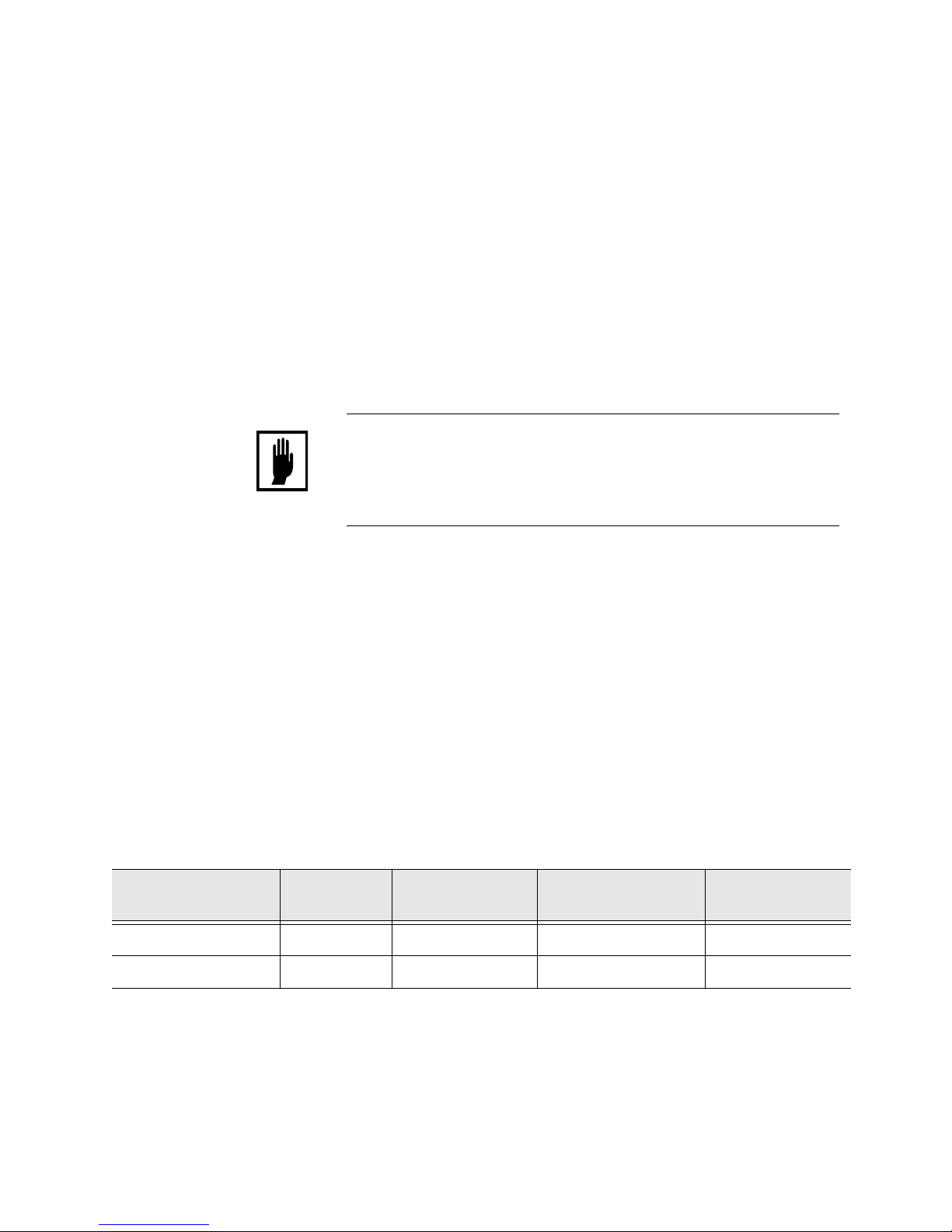
PROGRAM SECURITY
If this input is not jumpered, only data under the Stepper Status
Mode and Heat Display Mode can be changed.
This input is used in conjunction with the HEAT DISPLAY
SECURITY input, only data under the Stepper Display Mode can
be changed.
HEAT DISPLAY SECURITY
This input must be used in conjunction with the PROGRAM
MODE SECURITY input. If this input is not active (not jumpered),
NO changes can be made to any of the programmable data except
under the Stepper Status Mode.
User Inputs 1 – 8
These are generic inputs from the SLC. These inputs can be used to
force the timer unit to wait in a weld schedule using the user input
functions.
Table 1: Security Jumper Position
Control is
LOCKED
Control is Fully
Programmable
Only Heat Display is
Programmable
Control is Fully
Programmable
Program Security No Jumper Jumpered No Jumper Jumpered
Heat Security No Jumper No Jumper
Jumpered Jumpered
Page 46

Communications and I/O
3 - 8 MedWeld 5000 Technical Reference Manual
M-032170
Caution: These inputs are arbitrarily assigned numbers
from 1 -8. Do NOT confuse this label (for example,
Input #1) used by the weld function with an actual input
position. That is, User Input #1 is NOT
NECESSARILY assigned to input #1.
Outputs WELD VALVE Outputs (1 – 6)
These outputs are activated or de-activated when the MedWeld
3005 executes Function #54 (TURN ON WELD VALVE #n) or
Function #55 (TURN OFF WELD VALVE #n).
NOTE: Valves #1 and #2 are shared outputs; they function as the two Advance
(Fluid) valves when enabling Ohma cylinder operation for the processor.
PRESSURE SELECT Outputs (1 – 4)
These outputs are activated or de-activated when the MedWeld
3005 executes functions #56 (TURN ON PRESSURE SELECT #n)
and #57 (TURN OFF PRESSURE SELECT #n).
RETRACT 1 VALVE
RETRACT 2 VALVE
These outputs respond to the on/off status of the RETRACT
VALVE 1 and 2 PILOT Inputs, based on the Retract Mode setup
parameter.
ISOLATION CONTACTOR Output
This output is activated or de-activated when the MedWeld 3005
executes Function #88 (TURN ON ISOLATION CONTACTOR) or
Function #53 (TURN OFF ISOLATION CONTACTOR).
Function #77 (ISOLATION CONTACTOR DELAY nn SEC) also
affects this output, as described in the setup parameters.
The output is used to remove power from the high-voltage circuitry
when it is not required by the weld schedule.
SHUNT TRIP Output
This output is provided to trip the circuit breaker in case of a
catastrophic failure.
Page 47

Communications and I/O
MedWeld 5000 Technical Reference Manual 3 - 9
M-032170
WELD/NO WELD Output
When the WELD/NO WELD input is opened, it energizes this
output (to indicate that the control is in No Weld Mode). If a valid
weld initiate is received while the control is in No Weld Mode, the
weld schedule will schedule normally, BUT WELD CURRENT
WILL NOT FLOW.
FAULT Output
This output is normally OFF, indicating that the control is
functioning normally. If the control shuts down as the result of a
fault condition, this output will be turned ON.
NO FAULT Output
Certain applications use the NO FAULT output (rather than the
FAULT output above). This output is normally ON (to indicate that
no fault conditions exist). If the control shuts down as the result of a
fault condition, this output will be turned OFF.
NO ALERT Output
This output is normally ON. It turns OFF to indicate an alert
condition. Alert conditions are usually less serious than faults and
normally serve to warn the operator that maintenance is required.
ALERT Output
This output is normally OFF and turns on to indicate an alert
condition. Alert conditions are usually less serious than faults and
are normally used to warn the operator that maintenance is
required.
INITIATE ACKNOWLEDGE Output
This output indicates that the control is executing a schedule.
END OF STEPPER Output
The control will activate this output when the stepper completes the
last weld in the last step.
This output becomes active when one or more linear steppers has
reached the end of its program or one or more SureWeld steppers
has reached its programmed limit.
WELD IN PROGRESS Output
The control turns this output ON and OFF in response to the output
control function.
WELD COMPLETE Output
Page 48

Communications and I/O
3 - 10 MedWeld 5000 Technical Reference Manual
M-032170
This output turned on and off by the weld control in response to the
functions #50 & #51 in the weld schedule, TURN ON WELD
COMPLETE and TURN OFF WELD COMPLETE.
READY TO WELD Output
When active, this output indicates that the control is ready to weld
and will pass current if
The control is in Weld Mode,
• NO faults exist,
• The CONTROL STOP input is HIGH,
• The WCU is synchronized with the line voltage,
• System cooling is provided:
• The SCR OVER TEMP input is closed.
• When this output is activated, the RTW LED on the WTC timer
unit will light.
The output is de-activated when the RETRACT VALVE 1 (or 2)
PILOT input is de-activated, and the setup parameter Inhibit
Initiation from Retract is programmed.
STEPPER APPROACHING LAST STEP
For linear steppers, this output will activate when the control
reaches the start of the last step in the stepper profile.
For SureWeld steppers, this output will light when the control
reaches the programmed value in the Stepper Approaching Max.
Welds setup parameter.
WELD MISMATCH Output
This output is active to indicate that the control is in Weld Mode
and the data entry device is in No Weld Mode.
User Outputs (1-8)
These are generic outputs to the SLC. The timer unit turns these
outputs ON or OFF in a weld schedule, using the functions
described in
Caution: These outputs are arbitrarily assigned
numbers from 1– 8. Do NOT confuse this label (Output
#1, for example) used by the weld function with an
actual output position. That is, User Output #1 is NOT
NECESSARILY assigned to output #1.
Page 49
Communications and I/O
MedWeld 5000 Technical Reference Manual 3 - 11
M-032170
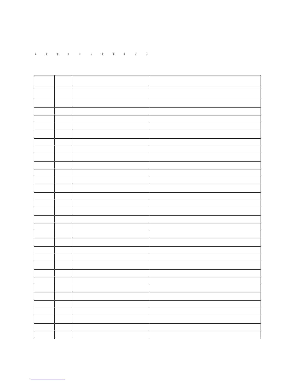
DeviceNet Bitmap
Number
Typ e
Name Description
1 Input Weld / No Weld Active high is Weld Mode, active low is No Weld
Mode.
2 Input Fault Reset Resets faults in timer / weld control.
3 Input Weld Fault Acknowledge Acknowledges a weld error.
4 Input Binary Select #1 Binary Select #1
5 Input Binary Select #2 Binary Select #2
6 Input Binary Select #4 Binary Select #4
7 Input Binary Select #8 Binary Select #8
8 Input Binary Select #16 Binary Select #16
9 Input Binary Select #32 Binary Select #32
10 Input Initiate Weld Initiates a weld schedule based upon Binary Select.
11 Input Spare Spare
12 Input Spare Spare
13 Input Stepper Reset Resets all steppers to zero.
14 Input Isolation Contactor Saver Enable Isolation Contactor Saver Enable bit
15 Input Control Stop Control Stop
16 Input Tips Dressed. Tips have been dressed.
17 Input Spare Spare
18 Input Spare Spare
19 Input Spare Spare
20 Input Spare Spare
21 Input Spare Spare
22 Input Spare Spare
23 Input Spare Spare
24 Input Spare Spare
25 Input Spare Spare
26 Input Spare Spare
27 Input Spare Spare
28 Input Spare Spare
29 Input Spare Spare
30 Input Spare Spare
31 Input Spare Spare
32 Input Spare Spare
Page 50
Communications and I/O
3 - 12 MedWeld 5000 Technical Reference Manual
M-032170
Number
Typ e
Name Description
1 Output Weld Enable Weld Mode On
2 Output No Fault No Faults Exist
3 Output No Alert No Alerts Exist.
4 Output Weld Fault Indicates that a weld fault error code is set
5 Output Weld Error Bit 1 Binary Bit for weld error code 1
6 Output Weld Error Bit 2 Binary Bit for weld error code 2
7 Output Weld Error Bit 4 Binary Bit for weld error code 4
8 Output Weld Error Bit 8 Binary Bit for weld error code 8
9 Output Weld Error Bit 16 Binary Bit for weld error code 16
10 Output Weld Complete Initiates a weld schedule has completed.
11 Output Weld in Progress Indicates that a weld is currently in progress.
12 Output Steppers are Reset Indicates that all steppers are reset.
13 Output Stepper Approaching Max Stepper has entered last step.
14 Output End of Stepper The last weld in the last step of the programmed
stepper was reached.
15 Output Ready to Weld The control is ready to begin welding.
16 Output Tip Dress Request The weld control is requesting a tip dress.
17 Output Spare Spare
18 Output Spare Spare
19 Output Spare Spare
20 Output Spare Spare
21 Output Spare Spare
22 Output Spare Spare
23 Output Spare Spare
24 Output Spare Spare
25 Output Spare Spare
26 Output Spare Spare
27 Output Spare Spare
28 Output Spare Spare
29 Output Spare Spare
30 Output Spare Spare
31 Output Spare Spare
32 Output Spare Spare
Page 51

Communications and I/O
MedWeld 5000 Technical Reference Manual 3 - 13
M-032170
DEP-100S Abbreviations
The DEP-100S provides an I/O Status display to help troubleshoot I/O
issues. The I/O Status display shows the current state of each input and
output.
Status indications are either a 0 or a 1. The number zero indicates the
input or output is inactive (low). The number one indicates that the input
or output is active (high).
The following tables list the abbreviations used to represent the I/O for
DeviceNet at the DEP-100S Programming Device.
Input Abbreviations
NOTE: The processor displays all of the possible I/O on the DEP-100S
programming device. However, only the Local and Safety I/O and the I/
O in the image table are accessible. For more details, refer to the
drawing package provided with your control.
BINARY SELECT #1 Input BS1
BINARY SELECT #2 Input BS2
BINARY SELECT #4 Input BS4
BINARY SELECT #8 Input BS8
BINARY SELECT #16 Input BS16
WELD SCHEDULE ENABLE Input INT
WELD/NO WELD Input (HIGH for weld) WLD
CONTROL STOP Input (HI = operational,
LOW = control stop) CSTP
ISOLATION CONTACTOR SAVER Input CSVR
REMOTE STEPPER RESET Input SR
FAULT RESET Input FR
PROGRAM MODE SECURITY Input PSEC
HEAT DISPLAY SECURITY Input HSEC
TIP DRESS/ADVANCE Input TIPD
PARITY (Odd) Input /BINARY SELECT #64 PTY
PRESSURE SWITCH Input PS1
WELD PROCEED Input WPRO
STEPPER AUXILIARY COUNTER RESET Input SACR
RETRACT PILOT #1 Input RP1
RETRACT PILOT #2 Input RP2
SYSTEM COOLING (SCR THERMAL SWITCH) Input COOL
ISOLATION CONTACTOR (AUXILIARY
CONTACTS) Input IC
User Input #1 UI1
User Input #2 UI2
User Input #3 UI3
User Input #4 UI4
User Input #5 UI5
User Input #6 UI6
User Input #7 UI7
User Input #8 UI8
Page 52

Communications and I/O
3 - 14 MedWeld 5000 Technical Reference Manual
M-032170
Output Abbreviations WELD IN PROGRESS Output WIP
WELD FAULT Output (LOW for fault) FLT
WELD ALERT Output ALT
WELD/NO WELD MISMATCH Output WM
STEPPER IS RESET Output SRST
WELD COMPLETE Output WCMP
READY TO WELD Output RTW
HAS WELDED Output HWO
END OF STEPPER Output EOS
STEPPER ALERT Output SALT
TIP DRESS REQUEST TPDR
STEPPER AUXILIARY COUNTER AT MAXIMUM SACM
VALVE #1/ADVANCE (Fluid) VALVE #1 Output VLV1
VALVE #2/ADVANCE (Fluid) VALVE #2 Output VLV2
VALVE #3 Output VLV3
VALVE #4 Output VLV4
VALVE #5 Output VLV5
VALVE #6 Output VLV6
RETRACT VALVE #1 RV1
RETRACT VALVE #2 RV2
PRESSURE SELECT #1 Output PV1
PRESSURE SELECT #2 Output PV2
PRESSURE SELECT #3 Output PV3
PRESSURE SELECT #4 Output PV4
INTENSIFICATION (Air) VALVE Output INTV
WELD/NO WELD Output (LOW for weld) WNO
ISOLATION CONTACTOR (SSR Relay) Output SSR
SHUNT TRIP Output PO2
INITIATE ACKNOWLEDGE Output IACK
User Output #1 UO1
User Output #2 UO2
User Output #3 UO3
User Output #4 UO4
User Output #5 UO5
User Output #6 UO6
User Output #7 UO7
User Output #8 UO8
Page 53

MedWeld 5000 Technical Reference Manual 4 - 1
M-032170
Weld Schedules 4
The MedWeld 5000 control is capable of storing up to 63 unique weld
schedules. Each weld schedule can then be assigned to one of 63
independent steppers.
This chapter does not describe how to create or modify a weld schedule.
(These steps will depend on the programming device.) This chapter only
describes all of the weld functions available for use in programming a
weld schedule.
What is a Weld Schedule?
A weld schedule is a list of commands that the control is to execute. For
example, to perform a simple spot weld, you might use a weld schedule
consisting of the following functions:
82 LINEAR STEPPER #0 ASSIGNED (0 = OFF)
76 SECONDARY CURRENT LIMIT HIGH=99999
LOW=00000
81 TRANSFORMER TURNS RATIO 73:1
58 TURN ON WELD IN PROGRESS
88 TURN ON ISOLATION CONTACTOR
01 SQUEEZE 30 CYCLES
20 WELD 10 CY. 10000 AMPS
59 TURN OFF WELD IN PROGRESS
63 TURN ON WELD COMPLETE
03 HOLD 05 CYCLES
64 TURN OFF WELD COMPLETE
89 TURN OFF ISOLATION CONTACTOR
Page 54

Weld Schedules
4 - 2 MedWeld 5000 Technical Reference Manual
M-032170
Software Capabilities
The MedWeld 5000 provides commands for:
• Assigning a stepper to a schedule,
• Defining a linear stepper program,
• Turning selected outputs on or off and
• Providing weld current.
Other functions enable
• Overriding the setup parameters,
• Controlling the I/O by monitoring inputs and activating outputs,
• Regulating weld current to fall within a prescribed range, and
repeat the weld if the current is not within that range,
• Statistical process control (SPC) functions,
• Selecting the firing mode (to assure consistent voltage or to assure
constant secondary current)
• Pausing in a schedule to wait for certain operating conditions to
become true.
The software allows users to add or delete functions from this list, or
change any of the numeric values specified in a function. This allows for
the creation of a schedule that meets your application requirements.
The following sections describe the functions available for use in a weld
schedule, including the two-digit function code and the action each
function produces.
The functions are grouped according to their purpose in a weld
schedule, and to aid your understanding their overall interaction.
Page 55

Weld Schedules
MedWeld 5000 Technical Reference Manual 4 - 3
M-032170
List of Functions for Software #F04100
NOTE: Unless otherwise indicated, nn represents any two-digit number from 0
– 99. nnn is a 3-digit number from 0 – 999. Exceptions to this convention
will appear next to the function.
MedWeld 5000
Funcitons
01 SQUEEZE nn CYCLES
02 COOL nn CYCLES
03 HOLD nn CYCLES
04 OFF nn CYCLES
05 INITIAL SQUEEZE nn CYCLES
06 QUENCH nn CYCLES
07 WAIT nn CYCLES
08 PRE-COMPRESSION
09 GUN WAIT DELAY
10 DELAY
11 PLATEN DELAY
12 WELD DELAY
13 METAL FORM TIME
20 WELD nn CY/IMP mm %I
21 TEMPER nn CY/IMP mm %I
22 PREHEAT nn CY/IMP mm %I
23 POSTHEAT nn CY/IMP mm %I
24 PRE-WELD nn CY/IMP mm %I
26 WELD nnnn MSEC mm %I
30 WELD nn CY/IMP nnnn0 AMPS
31 TEMPER nn CY/IMP nnnn0 AMPS
32 PREHEAT nn CY/IMP nnnn0 AMPS
33 POSTHEAT nn CY/IMP nnnn0 AMPS
34 PRE-WELD nn CY/IMP nnnn0 AMPS
35 MAXHEAT nn MSEC nnn uS nnnn0 AMPS
36 WELD nnnn MSEC nnnn0 AMPS
37 CHC WELD nn CY nnnn0 AMPS
40 UPSLOPE nn CY mm %I TO mm %I
41 DOWNSLOPE nn CY mm %I TO mm %I
42 PRESLOPE nn CY mm %I TO mm %I
43 POSTSLOPE nn CY mm %I TO mm %I
45 SLOPE nn CY nnnn0 AMPS TO nnnn0 AMPS
58 TURN ON WELD IN PROGRESS
59 TURN OFF WELD IN PROGRESS
60 IMPULSE = nn HEAT CY, nn COOL CY
61 ABORT IF NO INITIATE FOR nn CYCLES
62 REPEAT (AT NEXT FUNCTION)
Page 56

Weld Schedules
4 - 4 MedWeld 5000 Technical Reference Manual
M-032170
63 TURN ON WELD COMPLETE
64 TURN OFF WELD COMPLETE
65 ISOLATION CONTACTOR DELAY=nn SEC
75 EXTEND UNTIL NO INITIATE
76 SEC. CURR. LIMITS: HI = nnnn0 Low=nnnn0
81 TRANSFORMER TURNS RATIO nnn:1 (nnn=1-256)
82 LINEAR STEPPER #nn ASSIGNED (0 = OFF)
85 PROCESS WELD FAULTS
88 TURN ON ISOLATION CONTACTOR
89 TURN OFF ISOLATION CONTACTOR
99 GOTO SEQ #nn
Page 57

Weld Schedules
MedWeld 5000 Technical Reference Manual 4 - 5
M-032170
List of Functions for Software #F04300
NOTE: Unless otherwise indicated, nn represents any two-digit number from 0
– 99. nnn is a 3-digit number from 0 – 999. Exceptions to this convention
will appear next to the function.
01 SQUEEZE nn CYCLES
02 COOL nn CYCLES
03 HOLD nn CYCLES
04 OFF nn CYCLES
05 INITIAL SQUEEZE nn CYCLES
06 QUENCH nn CYCLES
07 WAIT nn CYCLES
08 PRE-COMPRESSION
09 GUN WAIT DELAY
10 DELAY
11 PLATEN DELAY
12 WELD DELAY
13 METAL FORM TIME
20 WELD nn CY/IMP mm %I
21 TEMPER nn CY/IMP mm %I
22 PREHEAT nn CY/IMP mm %I
23 POSTHEAT nn CY/IMP mm %I
24 PRE-WELD nn CY/IMP mm %I
26 WELD nnnn MSEC mm %I
30 WELD nn CY/IMP nnnn0 AMPS
31 TEMPER nn CY/IMP nnnn0 AMPS
32 PREHEAT nn CY/IMP nnnn0 AMPS
33 POSTHEAT nn CY/IMP nnnn0 AMPS
34 PRE-WELD nn CY/IMP nnnn0 AMPS
35 MAXHEAT nn MSEC nnn uS nnnn0 AMPS
36 WELD nnnn MSEC nnnn0 AMPS
37 CHC WELD nn CY nnnn0 AMPS
40 UPSLOPE nn CY mm %I TO mm %I
41 DOWNSLOPE nn CY mm %I TO mm %I
42 PRESLOPE nn CY mm %I TO mm %I
43 POSTSLOPE nn CY mm %I TO mm %I
45 SLOPE nn CY nnnn0 AMPS TO nnnn0 AMPS
58 TURN ON WELD IN PROGRESS
59 TURN OFF WELD IN PROGRESS
60 IMPULSE = nn HEAT CY, nn COOL CY
61 ABORT IF NO INITIATE FOR nn CYCLES
62 REPEAT (AT NEXT FUNCTION)
63 TURN ON WELD COMPLETE
Page 58

Weld Schedules
4 - 6 MedWeld 5000 Technical Reference Manual
M-032170
64 TURN OFF WELD COMPLETE
65 ISOLATION CONTACTOR DELAY=nn SEC
75 EXTEND UNTIL NO INITIATE
76 SEC. CURR. LIMITS: HI = nnnn0 Low=nnnn0
81 TRANSFORMER TURNS RATIO nnn:1 (nnn=1-256)
82 LINEAR STEPPER #nn ASSIGNED (0 = OFF)
85 PROCESS WELD FAULTS
88 TURN ON ISOLATION CONTACTOR
89 TURN OFF ISOLATION CONTACTOR
99 GOTO SEQ #nn
Page 59
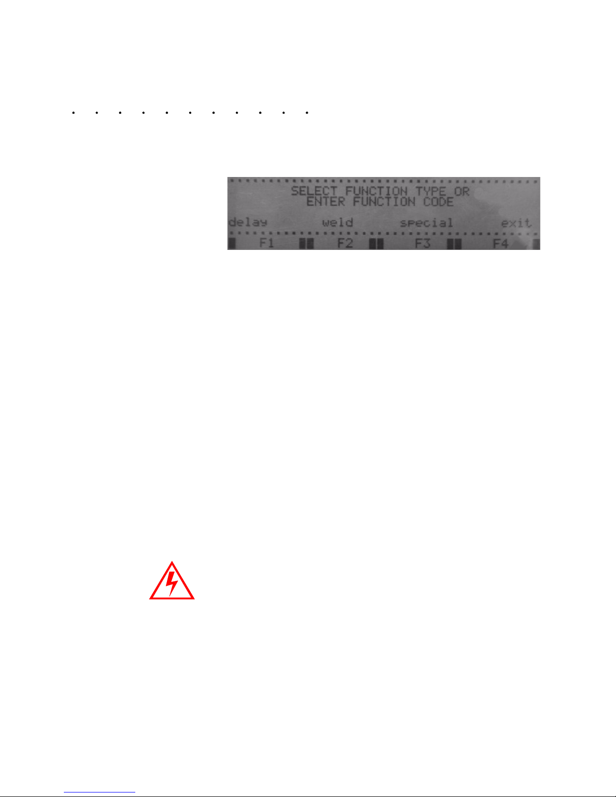
Weld Schedules
MedWeld 5000 Technical Reference Manual 4 - 7
M-032170
Function Descriptions
This section will list functions by group and give descriptions of
function operation. When entering a function via the DEP, the functions
are grouped by Delay, Weld and Special.
Delay Functions Delay functions all have the same effect on the weld schedule: They
cause the control to wait for the number of cycles specified. (Different
names are assigned for describing the reasons for a delay.)
During these functions, weld current does not flow and I/O status is not
changed. Open the list of delay functions on the DEP by pressing F1.
01 SQUEEZE nn CYCLES
02 COOL nn CYCLES
03 HOLD nn CYCLES
04 OFF nn CYCLES
05 INITIAL SQUEEZE nn CYCLES
06 QUENCH nn CYCLES
07 WAIT nn CYCLES
08 PRE-COMPRESSION
09 GUN WAIT DELAY
10 DELAY
11 PLATEN DELAY
12 WELD DELAY
13 METAL FORM TIME
Weld
Functions
Weld functions provide a specified amount of weld current for the
number of cycles programmed. The function entered also selects the
type of firing mode desired.
NOTE: Faults may occur when the control is firing at or near the high and low
range of current for both ACC or AVC. The current range for each
control is unique and depends on factors such as the size of the weld
transformer, actual power capacity and nominal line voltage.
Experiment with the control to determine the upper and lower range of
current each control can provide.
20 WELD nn CY/IMP mm %I
Page 60

Weld Schedules
4 - 8 MedWeld 5000 Technical Reference Manual
M-032170
21 TEMPER nn CY/IMP mm %I
22 PREHEAT nn CY/IMP mm %I
23 POSTHEAT nn CY/IMP mm %I
24 PRE-WELD nn CY/IMP mm %I
26 WELD nnnn MSEC mm %I
30 WELD nn CY/IMP nnnn0 AMPS
31 TEMPER nn CY/IMP nnnn0 AMPS
32 PREHEAT nn CY/IMP nnnn0 AMPS
33 POSTHEAT nn CY/IMP nnnn0 AMPS
34 PRE-WELD nn CY/IMP nnnn0 AMPS
36 WELD nnnn MSEC nnnn0 AMPS
37 CHC WELD nn CY nnnn0 AMPS
40 UPSLOPE nn CY nn %I TO nn %I
41 DOWNSLOPE nn CY nn %I TO nn %I
42 PRESLOPE nn CY nn %I TO nn %I
43 POSTSLOPE nn CY nn %I TO nn %I
45 SLOPE nn CY nnnn0 AMPS TO nnnn0 AMPS
The weld function you select also tells the timer unit the type of firing
mode to use to control the energy provided to a weld. Specify weld
current as either:
• A percentage of maximum available current, or
• The amount of secondary current.
Weld functions having %I at the end of the function (shown in function
numbers 20-26) use Automatic Voltage Compensation. Functions using
the AVC firing mode specify weld current as nn%I when firing in cycles
or mm %I when firing in milliseconds (represent the percentage of
maximum available current). AVC monitors primary voltage. It uses a
nominal voltage reference point (programmed in the setup parameters)
to determine when compensation is required for voltage swings on the
weld bus.
Weld functions that have AMPS at the end of the function (shown in
functions 30-37) have Automatic Current Compensation. Functions
using the ACC firing mode specify a set amount of secondary current,
displayed as nnnnn AMPS. ACC monitors the current during each
cycle. It compensates for changes detected during the next cycle, to
maintain secondary current at the level programmed. This method does
NOT compensate for changes in the welder secondary circuit.
Caution: The Transformer Turns Ratio setup parameter
must be accurately programmed for the control to
supply the correct amount of secondary current in ACC
firing mode.
Page 61

Weld Schedules
MedWeld 5000 Technical Reference Manual 4 - 9
M-032170
NOTE: The weld data generated by the control (and displayed at the DEP or a
data monitoring device) does NOT include every function that provides
weld current. Keep this in mind when programming a weld schedule.
Only the following functions are included in the Weld Data display:
Weld Functions
Using Automatic
Vo l t a g e
Compensation
20 WELD nn CY/IMP mm %I *
21 TEMPER nn CY/IMP mm %I
22 PREHEAT nn CY/IMP mm %I
23 POSTHEAT nn CY/IMP mm %I
24 PRE-WELD nn CY/IMP mm %I
26 WELD nnnn MSEC mm %I *
* The stepper is active during this function.
NOTE: When Function IMPULSE= nn HEAT CY, nn COOL CY (nn=1-99)
appears before any weld function in a schedule, the control displays IMP
(impulses) rather than CY (cycles) to indicate the weld control will
pulsation weld.
Time (Cycles)
99%
20%
%I
20 cycles
60%I
WELD 20 CY 60%I
Page 62

Weld Schedules
4 - 10 MedWeld 5000 Technical Reference Manual
M-032170
Weld Functions Using
Automatic Current
Compensation
ACC is the Automatic Current Compensation firing mode. This mode
programs all values of weld current in A. For a programmed value of
weld current, the control will pass this amount of current during the
WELD function, regardless of the amount of metal in the weld gun’s
throat or the stack-up of metal. (This applies ONLY if the welding
system can deliver the requested current.)
The following weld functions will select the ACC firing mode.
30 WELD nn CY/IMP nnnn0 AMPS*
31 TEMPER nn CY/IMP nnnn0 AMPS
32 PREHEAT nn CY/IMP nnnn0 AMPS
33 POSTHEAT nn CY/IMP nnnn0 AMPS
34 PRE-WELD nn CY/IMP nnnn0 AMPS
35 MAXHEAT nn MS BELOW nnn us nnnn0 AMPS
36 WELD nnnn MSEC nnnn0 AMPS
37 CHC WELD nn CY nnnn0 AMPS
*The stepper is active during this function.
This example depicts firing in ACC mode. The WELD function fires a
secondary current of 5,000 A. The specified 5,000 A. of current will be
maintained for 20 cycles. ACC functions apply current either by cycles,
or in impulses. These functions weld, temper, pre-heat, post-heat or preweld.
WARNING! You MUST specify the correct
transformer turns ratio (especially if the welding
transformer has multiple secondary taps).
Obtain this data from the transformer’s rating
plate or manufacturer.
20 cycles
Secondary
05000 A.
WELD 20 CY 05000 AMPS
Time (Cycles)
current (A.)
Page 63

Weld Schedules
MedWeld 5000 Technical Reference Manual 4 - 11
M-032170
The Transformer Turns Ratio value must be
accurately programmed for the control to
supply the correct amount of secondary current
while firing in ACC mode. An exception is when
firing in Secondary Current mode while using a
secondary-current sensing device. Then,
secondary current is a direct reading, without
calculations regarding the turns ratio.
NOTES: When the function IMPULSE= nn HEAT CY, nn COOL CY (nn=1-
99) appears before any weld function in a schedule, the control displays
IMP (impulses) rather than CY (cycles) to indicate the weld control will
pulsation weld.
35 MAXHEAT nn MS BELOW nnn us nnnn0 AMPS
This function is used when welding special insulated metals, or "quiet
steel" metals. The function MAXHEAT is a preheating function used to
breakdown the insulating properties of the material between the metal.
MAXHEAT was designed to create a threshold level based on the
preheat time (nn = milliseconds), on time of the inverter (nnn = on
time), and nnnn0, which is the current needed to break through the
insulation between the metal. This function is typically followed by a
standard weld function.
This preheat function starts with an 8 millsecond blanking cycle, after
the blanking cycle, the control waits for the on time to be below the
programmed value (nnn = on time threshold), the executes a preheat for
nn milliseconds for nnnn0 amps.
If the 8 millisecond blanking cycle does not complete, the operator will
see "LOW LIMIT FAULT". If the MAXHEAT exceeds 40 cycles, a
"HIGH LIMIT FAULT".
Page 64

Weld Schedules
4 - 12 MedWeld 5000 Technical Reference Manual
M-032170
Weld Functions that
Adjust Current
Functions #40–43 use AVC firing to adjust weld current. Function #45
provides firing in constant current (ACC).
40 UPSLOPE nn CY nn %I TO nn %I
41 DOWNSLOPE nn CY nn %I TO nn %I
42 PRESLOPE nn CY nn %I TO nn %I
43 POSTSLOPE nn CY nn %I TO nn %I
45 SLOPE nn CY nnnn0 AMPS TO nnnn0 AMPS
These functions provide weld current that starts at the first value and
slopes linearly to the second value over the number of cycles specified.
Every function fires for the number of cycles specified. For example,
the function
40 UPSLOPE 30 CY 45% I TO 65% I
tells the control to fire one cycle at 45% of the maximum available heat.
Then, over the next 29 cycles, gradually increase the heat provided to
65%.
41 DOWNSLOPE 30 CY 65% I TO 45% I
This function tells the control to fire one cycle at 65% of the maximum
available heat. Then, over the next 29 cycles, gradually decrease the
heat provided to 45%.
42 PRESLOPE 30 CY 45% I TO 65% I
tells the control to fire one cycle at 45% of the maximum available heat.
Then, over the next 29 cycles, gradually increase the heat provided to
65%.
43 POSTSLOPE 30 CY 65% I TO 45% I
tells the control to fire one cycle at 65% of the maximum available heat.
Then, over the next 29 cycles, gradually decrease the heat provided to
45%.
45 SLOPE 30 CY 5000 AMPS TO 10000 AMPS
This function tells the control to fire one cycle at 5000 AMPS. Then,
over the next 29 cycles, gradually increase the heat provided to 10000
AMPS. This function is an open function, it can either slope "up" or
slope "down" depending on how the operator enters the function.
However, by defining the slope as an impulse (Function
IMPULSE=
nn HEAT CY, nn COOL CY (nn=1-99)
appears before this function
in the schedule), the timer unit gradually increases the energy provided
by each impulse, until it has sloped to the desired energy.
Page 65

Weld Schedules
MedWeld 5000 Technical Reference Manual 4 - 13
M-032170
For example, the following two functions will have the action shown in
the diagram below
60 IMPULSE= nn HEAT CY, nn COOL CY (nn=1-99)
This function defines the length of a weld impulse. It tells the timer unit
that the next function in the schedule should pulsation weld (providing
heat cycles followed by cool cycles, rather than just heat cycles).
When this function appears before any weld function, the control
displays IMP (impulse) rather than CY (cycles) to indicate the weld
control will pulsation weld.
Pulsation welding provides a specified number of impulses. (An
impulse is a number of heat cycles—when weld current flows—
followed by a number of cycles when current does not flow.) Consider
the following schedule:
60 IMPULSE = 10 HEAT CY, 10 COOL CY
20 WELD 04 IMP 65%I
In this example, the timer unit will actually fire for 10 cycles at 65%
heat, then wait for 10 cycles with NO heat, and repeat this pattern 4
times.
This function only affects the next function in a weld schedule. It should
appear before every weld or slope function you want to pulsation weld
in the schedule.
99%
20%
%I
3cy
8cy 8cy
3cy 3cy
40%
45%
50%
IMPULSE=03 HEAT CY, 08 COOL CY
SLOPE 03 IMP 40%I TO 50%I
Time (Cycles)
Page 66

Weld Schedules
4 - 14 MedWeld 5000 Technical Reference Manual
M-032170
Special Functions These functions allow the control to turn outputs on or off within a weld
schedule.
58 TURN ON WELD IN PROGRESS
59 TURN OFF WELD IN PROGRESS
60 IMPULSE = 10 HEAT CY, 10 COOL CY
61 ABORT IF NO INITIATE FOR nn CYCLES
62 REPEAT (AT NEXT FUNCTION)
63 TURN ON WELD COMPLETE
64 TURN OFF WELD COMPLETE
65 ISOLATION CONTACTOR DELAY (SEC): (0–99)
75 EXTEND UNTIL NO INITIATE
76 SEC. CURR. LIMITS: HI = nnnn0 Low=nnnn0
81 TRANSFORMER TURNS RATIO nnn:1 (nnn=1-256)
82 LINEAR STEPPER #nn ASSIGNED (0 = OFF)
85 PROCESS WELD FAULTS
88 TURN ON ISOLATION CONTACTOR
89 TURN OFF ISOLATION CONTACTOR
99 GOTO SEQ #nn
Special Function
Definitions
58 TURN ON WELD IN PROGRESS
The control turns this output ON when a weld is currently in progress.
59 TURN OFF WELD IN PROGRESS
The control turns this output OFF when a weld in progress has com-
pleted.
60 IMPULSE = 10 HEAT CY, 10 COOL CY
This function defines the length of a weld impulse. It tells the timer unit
that the next function in the schedule should pulsation weld (providing
heat cycles followed by cool cycles, rather than just heat cycles).
61 ABORT IF NO INITIATE FOR nn CYCLES
This function tells the control to verify that the weld initiate has
remained active. The control waits the number of cycles programmed
while checking the initiates. If the initiates are not present at any time
while it is waiting, the control will abort the sequence and generate the
WELD INITIAT NOT PRESENT fault.
62 REPEAT (AT NEXT FUNCTION)
This function also monitors the status of the weld initiate. When the
control completes a weld schedule, it repeats the remaining functions in
the schedule. At the end of the schedule, it returns to the repeat function,
Page 67

Weld Schedules
MedWeld 5000 Technical Reference Manual 4 - 15
M-032170
again checks the status of the WELD INITIATE input, and repeats the
rest of the schedule. This continues until the processor detects that the
WELD INITIATE input has been removed.
NOTE: Functions #62 and #75 are mutually exclusive. They should NOT appear
in the same sequence.
63 TURN ON WELD COMPLETE
Function #63 (TURN ON WELD COMPLETE) will only activate the
WELD COMPLETE output under the following conditions: There are
no active fault conditions, AND the BINARY SELECT or WELD
INITIATE input is still active.
This function only processes the weld data: It does NOT update the
FAULT and ALERT outputs. These outputs will be updated when the
control executes the function TURN ON WELD COMPLETE OR at the
end of the weld schedule.
This function will be executed only once by the processor. If it appears
more than once in the schedule, it will be executed the first time it
appears in the weld schedule.
64 TURN OFF WELD COMPLETE
Function #64 (TURN OFF WELD COMPLETE) will deactivate the
WELD COMPLETE output under the following conditions: a fault
occurs, AND the BINARY SELECT or WELD INITIATE input is still
active.
65 ISOLATION CONTACTOR DELAY (SEC): (0–99)
This parameter tells the control how long to hold the isolationcontactor
pulled in after the function TURN OFF ISOLATION CONTACTOR
executes. This is designed to prevent wear on the isolation contactor
caused by dropping in and out between welds. If ISOLATION
CONTACTOR SAVER input is available and set LOW, it disables this
delay timer.
75 EXTEND UNTIL NO INITIATE
This function tells the timer unit to monitor the status of the WELD
INITIATE input, and to extend only the previous function in the weld
schedule until it detects that the WELD INITIATE input is inactive.
NOTE: Functions #62 and #75 are mutually exclusive. They should NOT appear
in the same sequence.
76 SEC. CURR. LIMITS: HI = nnnn0 Low=nnnn0
If setting the FIRING MODE: to (SEC CURRENT) in this setup
parameter, the SEC. CURR. LIMITS function sets a maximum and
minimum AMP value.
If the weld control detected that the current fired
during the weld schedule exceeded the high or low current limit a fault
will occur.
NOTE: The function SEC. CURR. LIMITS sets limits that are unique to a given
weld schedule. The new limits override the limits programmed in the
Page 68

Weld Schedules
4 - 16 MedWeld 5000 Technical Reference Manual
M-032170
setup parameters. They apply only to the weld schedule where they
appear. They also take priority over any other limits established.
81 TRANSFORMER TURNS RATIO nnn:1 (nnn=1-256)
This parameter tells the control the turns ratio of the welding
transformer used. This lets the control determine secondary current
during a weld. (Secondary current equals the primary current multiplied
by the turns ratio.)
NOTE: The function TRANSFORMER TURNS RATIO sets limits that are unique
to a given weld schedule. The new limits override the limits programmed
in the setup parameters. They apply only to the weld schedule where they
appear. They also take priority over any other limits established.
82 LINEAR STEPPER #nn ASSIGNED (0 = OFF)
Function #82 assigns a linear stepper to a weld schedule.
The MedWeld 5000 has 63 independent linear steppers. Linear steppers
have 5 programmable levels (called “steps”) to provide additional
energy. When either function appears in a weld schedule, the
appropriate stepper is advanced (incremented) each time you execute
the weld schedule.
If Function 82 is used in a weld schedule it MUST be the first function
in the schedule.
Valid stepper numbers are 1 – 63. To disable a stepper for a schedule,
assign the stepper as zero (#0).
85 PROCESS WELD FAULTS
This function provides a one-cycle delay in the weld schedule. It asks
the MedWeld 5000 to indicate any faults that may have been generated
so far in the schedule.
88 TURN ON ISOLATION CONTACTOR
The function TURN ON ISOLATION CONTACTOR will first check to
determine if the isolation contactor is already closed, and will pull in the
isolation contactor only if it is open. This is designed to improve the
process speed, bypassing the delay provided to wait for the isolation
contactor to close.
89 TURN OFF ISOLATION CONTACTOR
The function TURN OFF ISOLATION CONTACTOR will first check
to determine if the isolation contactor is closed, and will release the
isolation contactor only if it is open. Stepper Assignment Functions
85 PROCESS WELD FAULTS
This function provides a one-cycle delay in the weld schedule. It asks
the MedWeld 5000 to indicate any faults that may have been generated
so far in the schedule.
Page 69

Weld Schedules
MedWeld 5000 Technical Reference Manual 4 - 17
M-032170
The control normally processes all fault conditions at the end of the
weld schedule. This function allows forcing the control to process fault
conditions before it completes the weld schedule. It should appear in the
weld schedule BEFORE any functions that check fault status or require
current weld data.
Caution: This function also causes the control to
calculate the voltage, current and power factor averages
and the C-factor for the weld. It also terminates the
weld summary data collection, to assure the integrity of
the weld data collected.
99 GOTO SEQ#nn (nn = 1-99)
This function is an unconditional jump to another weld schedule. It tells
the control to stop the present weld schedule, and continue with the first
function in another schedule.
This function can be used to save memory space in the control, by
allowing multiple schedules to execute commonly-used functions.
The control considers the schedule originally initiated as the last
schedule. The stepper assigned to the original schedule is also the only
one incremented. This function should appear as the last function in a
schedule, because the control will not return to the original schedule
when it completes the new schedule.
Caution: It is possible to create an infinite programming
loop with Functions #98 (GOTO SEQ #nn IF
CURRENT LESS THAN nnnn0 AMPS) and #99.
Page 70

Weld Schedules
4 - 18 MedWeld 5000 Technical Reference Manual
M-032170
Default Weld Sequence: Robot
START OF SEQUENCE #nn
82 LINEAR STEPPER #0 ASSIGNED (0 = OFF)
76 SECONDARY CURRENT LIMIT HIGH=99999
LOW=00000
81 TRANSFORMER TURNS RATIO 73:1
58 TURN ON WELD IN PROGRESS
88 TURN ON ISOLATION CONTACTOR
01 SQUEEZE 30 CYCLES
20 WELD 10 CY. 10000 AMPS
59 TURN OFF WELD IN PROGRESS
63 TURN ON WELD COMPLETE
03 HOLD 05 CYCLES
64 TURN OFF WELD COMPLETE
89 TURN OFF ISOLATION CONTACTOR
END OF SEQUENCE #nn
Default Weld Sequence: Machine
Following is the default sequence for a welding machine. Sequences 1 –
15 default to this sequence. Sequences 16 – 31 are defaulted to blank.
START OF SEQUENCE #nn
82 LINEAR STEPPER #0 ASSIGNED (0 = OFF)
76 SECONDARY CURRENT LIMIT HIGH=99999
LOW=00000
81 TRANSFORMER TURNS RATIO 73:1
58 TURN ON WELD IN PROGRESS
88 TURN ON ISOLATION CONTACTOR
01 SQUEEZE 30 CYCLES
20 WELD 10 CY. 30% AMPS
59 TURN OFF WELD IN PROGRESS
63 TURN ON WELD COMPLETE
03 HOLD 05 CYCLES
64 TURN OFF WELD COMPLETE
89 TURN OFF ISOLATION CONTACTOR
END OF SEQUENCE #nn
NOTE: The Machine defaults were designed as a testing solution for the WTC
control test department. Reloading from Machine defaults will load the
WTC standard control test defaults for firing loads. WTC does not
recommend using these defaults in an actual welding application.
Page 71

MedWeld 5000 Technical Reference Manual 5 - 1
M-032170
Advanced Software Features 5
This chapter describes some of the advanced features of the MedWeld
5000 control.
C-Factor
C-Factor is the value of current obtained for each change in percentage
of the maximum secondary current delivered. This value equals 1% of
the total available current during a weld.
The C-Factor can be used in various ways:
• It can be used as a conversion factor between %I values and the
actual value of current that would be produced.
• A change in C-Factor will indicate changes in the welding
environment.
The MedWeld 5000 calculates the actual C-Factor after every weld. The
programming device will display this value in its Weld Data display.
C-Factor is a theoretical maximum only. It does not take into account
the ratings of the weld control or transformer. C-Factor may possibly
exceed what the system can deliver, based on these ratings.
C-Factor is NOT accurate for extremely low currents, where the current
in the welding transformer’s secondary is not continuous.
C-Factor = I x x = x
pri
n
%I
I
%I
sec
V
nominal
V
line
V
nominal
V
line
Page 72

Advanced Software Features
5 - 2 MedWeld 5000 Technical Reference Manual
M-032170
Dynamic Current Windows
You can define a window of acceptable values for current. To define this
window, use the setup parameters: High Current Limit and Low Current
Limit.
These parameters, along with the Nominal C-Factor parameter, define
the acceptable range of current to expect. You can also override the
values in the setup parameters by inserting into the weld schedule
Function #84 (WINDOW: HI=+00% LO=00% C-FACTOR=000).
Function #84 defines a current limit window with high and low limit
values and a new nominal C-Factor. (Refer to the discussion of C-Factor
on page 7-1.)
The target current is determined by the firing mode used by the weld
function: %I or automatic current compensation. This calculation is
shown below:
AVC:
Target current
=
(%I programmed in Function #20 + stepper boost) x C-Factor
ACC:
Target current
=
A. programmed in Function #30 + stepper boost
Calculate the high and low current limits using this equation:
AV C E x a m p l e In this mode, the target value is determined by the following calculation:
Target current
=
%I in Function #20 + Stepper boost x C-factor
An example of how these calculations are used is shown below:
• Function #20 is WELD 10 CY 50%I
• Stepper Boost is 2%
• C-Factor is 170
• High Current Limit = 10%
• Low Current Limit = 20%.
To determine the target current:
Limit = Target current + Target current x
()
HI or LO Limit percentage
100 %
Page 73

Advanced Software Features
MedWeld 5000 Technical Reference Manual 5 - 3
M-032170
Target current
=
(%I programmed in Function #20 + Stepper boost) x C-Factor
= (50 + 2) x 170 = 8,840 A.
To determine the High Current Limit:
High Current Limit
= Target + (Target x %High Limit/100)
= 8,840 + (8,840 x 10/100)
= 8,840 + (884) = 9,724 A.
To determine the Low Current Limit:
Low Current Limit
= Target – (Target x %Low Limit/100)
= 8,840 – (8,840 x 20/100)
= 8,840 – (1,768) = 7,072 A.
ACC Firing Mode In this firing mode, the target value is established by the following
calculation:
Target current
= A. in Function #30 + Stepper boost
An example of how these calculations are used is shown below.
• Function #30 is WELD 08 CY 11000 A. SEC
• Stepper Boost is 700 A. SEC
• High Current Limit = 10%
• Low Current Limit = 20%
To determine the Target Current:
Target current
= A. in Function #30 + stepper boost
= 11,000 + 700 = 11,700 A.
To determine the High Current limit:
High Current Limit
= Target + (Target x %High limit/100)
= 11,700 + (11,700 x 10/100)
= 11,700 + (1170) = 12,870 A.
To determine the Low Current Limit:
Low Current Limit
= Target – (Target x %Low limit/100)
= 11,700 – (11,700 x 20/100)
= 11,700 – 2,340 = 9,360 A.
Page 74

Advanced Software Features
5 - 4 MedWeld 5000 Technical Reference Manual
M-032170
SPC Indexing Capabilities
With SPC (Statistical Process Control) Indexing, the control collects
weld data in temporary storage bins. This data can be collected either in
controlled intervals or continuously for use in special situations (such as
tear-down).
The collected weld data can be analyzed to help recognize certain
welding trends such as changes in resistance of the work piece, primary
current and line voltage.
You can then use WTC’s WebVIEW to retrieve and analyze the stored
data.
To perform SPC indexing, use the following functions in a weld
schedule, along with the SPC setup parameters described below.
SPC Functions 87 SET SPC OFFSET TO nn
For data collection, each weld is assigned a data storage bin number (00
– 99). This function establishes the starting bin number for SPC
indexing. Here is an example:
Car Type #1:
Weld Schedule #20 - (SET SPC OFFSET TO 01)
Weld Schedule #01 - 15 Welds Made (Bins 1–15)
Weld Schedule #02 - 15 Welds Made (Bins 16–30)
Weld Schedule #03 - 18 Welds Made (Bins 31–48)
Car Type #2:
Weld Schedule #21 - (SET SPC OFFSET TO 51)
Weld Schedule #04 - 12 Welds Made (Bins 51–62)
Weld Schedule #05 - 12 Welds Made (Bins 63–74)
Weld Schedule #06 - 14 Welds Made (Bins 75–88)
After establishing a bin number, the program stores the data for each
weld made in its own individual bin. The bin numbers increase by one
each time a weld is made, until another schedule with a different offset
is executed.
Bin #99 is the last usable bin. If the weld control reaches bin #99 and is
still collecting data, the data for each weld will be stored in bin #99 until
a new offset is assigned. For this reason, the data unsuitable for analysis.
NOTE: This function does NOT tell the control to collect weld data. It only
assigns a data storage bin number. Refer to the Data Collection Sample
Size and Data Collection Sample Frequency setup parameters described
below for instructions on how to specify data collection.
Page 75

Advanced Software Features
MedWeld 5000 Technical Reference Manual 5 - 5
M-032170
88 SEND ALL SAMPLES UNTIL NEXT SPC OFFSET
This function tells the control to start collecting weld data for all welds.
This function should follow the SET SPC OFFSET function in the weld
schedule because it is still necessary to assign a starting bin number.
Weld data collection continues until the control executes another
schedule containing this function (without the offset function), to reset
the global data collection process.
This function overrides the global Data Collection Sample Size and
Data Collection Sample Frequency setup parameters. These are
described next.
Caution: This function is NOT designed for use in a
normal production run. It is intended for special
situations (such as tear-down) which require
continuous data collection.
SPC setup Parameters DATA COLLECTION SAMPLE SIZE: 05 (1–99)
DATA COLLECTION SAMPLE FREQUENCY:0100 (1–9999)
These two parameters set a global command which allows the weld
control to sample data for analysis at controlled intervals.
The sample size is the amount of weld data collected for analysis
(number of consecutive welds, per bin). The sample frequency is the
total number of welds per bin, where data was collected (the samples are
taken from).
For example, by setting the Data Collection Sample Size parameter to 2
and the Data Collection Sample Frequency parameter to 8, the control
will collect weld data for 2 consecutive welds (in bin #1), and flag the
XWSS to retrieve the data. It will then collect data for 6 more cycles
(without flagging XWSS) before starting the process again.
The example table on the next page is for Bin #1 ONLY.
Page 76

Advanced Software Features
5 - 6 MedWeld 5000 Technical Reference Manual
M-032170
NOTE: Weld Data Collection is bin dependent. Each bin has its own independent
counter and is uploaded to WebVIEW separately.
Sample/
Frequency
WCU Process WIS/WSS Process
1/8 Data flagged for retrieval Data uploaded
2/8 Data flagged for retrieval Data uploaded
3/8 Data collected Data ignored
4/8 Data collected Data ignored
5/8 Data collected Data ignored
6/8 Data collected Data ignored
7/8 Data collected Data ignored
8/8 Data collected Data ignored
1/8 Data flagged for retrieval Data uploaded
2/8 Data flagged for retrieval Data uploaded
3/8 Data collected Data ignored
4/8 Data collected Data ignored
5/8 Data collected Data ignored
6/8 Data collected Data ignored
7/8 Data collected Data ignored
8/8 Data collected Data ignored
Page 77

Advanced Software Features
MedWeld 5000 Technical Reference Manual 5 - 7
M-032170
Retract Features
This section details the retract operation and how certain programmable
functions and setup parameters affect the operation:
• Retract Mode
• Initiate from Retract.
WARNING! For safety, the MedWeld 5000 ignores any
changes to these parameter settings until power
is removed from the control. (The control
checks the status of these parameters only at
power-up.)
Retract Mode Setup
Parameter
The Retract Mode setup parameter determines how the control will react
to the presence of an active RETRACT PILOT input.
• UNLATCHED tells the control to let the output for the Retract
valve follow the state of the RETRACT PILOT input. This is for
applications which use a toggle or selector switch. (The output will
be active while the input is active.) For air-only and OHMA
cylinders, the HIGH state of the RETRACT PILOT input(s)
indicates the partially-closed position. The LOW state indicates the
fully-open position.
• LATCHED tells the control to change the state of the output each
time it receives a pulse from the RETRACT PILOT input. (The
control expects a brief pulse from the input, such as from a push
button.)
• For air-normal operation, the HIGH state of the RETRACT valve(s)
indicates the partially-closed position. The LOW state indicates the
fully-open position.
• For air-inverted operation, the LOW state of the RETRACT
valve(s) indicates the partially-closed position. The HIGH state
indicates the fully-open position.
NOTE: Selecting LATCHED retract may require toggling the state of the
RETRACT PILOT input at power-up (to change the state of the
RETRACT VALVE output). This will be required if the control powers up
in the incorrect retract state, or if the of the RETRACT PILOT input
status changes while the control is in a C-Stop condition (the CONTROL
STOP input is LOW).
Page 78

Advanced Software Features
5 - 8 MedWeld 5000 Technical Reference Manual
M-032170
Initiation From
Retract
The processor also provides a function which you can place in a weld
schedule to tell the control to check whether the selected cylinder is out
of retract. Function #89 (VERIFY CYLINDER #n IS OUT OF
RETRACT) will abort the schedule and generate a RETRACT PILOT
fault if the cylinder is NOT out of retract.
NOTE: Program the RETRACT PILOT fault as an ALERT condition in the setup
parameters, so the operator can place the valve in the partial retract
position and re-initiate the weld schedule.
If this condition is defined as a FAULT, the control will require a fault
reset before it can continue. (An exception is when the Initiation On
Fault setup parameter is set to ALLOW).
If the weld schedule does NOT contain this function, the control will
allow you to execute a sequence with the gun in the full retract position.
DEP-100S Programming Restrictions
The software or greater has features that modify operation of the DEP100S (Data Entry Panel). These include changes to the operation of the
stepper, the ability to select No Weld operation and restrictions on
inserting and deleting certain functions.
As described in the DEP-100S Programming Guide, the information
you see will vary, based on the software contained in the weld processor.
This section describes how the DEP operation varies from the standard.
Weld/No Weld
Status
The DEP’s Display Mode provides an option called W/NW STATUS. It
allows changing the software setting at the weld processor from Weld to
NoWeld.
This feature is NOT supported by this version of the MedWeld 5000
software. The Display Mode does not provide the W/NW STATUS
option on its display.
Page 79

Advanced Software Features
MedWeld 5000 Technical Reference Manual 5 - 9
M-032170
Viewing Weld Data Software supporting the MFDC displays data on the Weld Data screen
on the DEP-100S (Hand-Held Terminal) differently from that for AC
welding controls. This section describes the differences in the Weld
Data screen:
max
avg
low
These three rows indicate the maximum, average and
minimum values read during the last weld.
busV This value is the INVERTER DC BUS voltage. The low
can typically be as much as 100 VDC below the average.
For diagnostic purposes, the AVG should be monitored.
If average voltage keeps decreasing over time, this could
point to the capacitors degrading and wearing out.
secI This value represents the secondary current the inverter
is firing. This value can be very low, as it indicates the
current being delivered during the first MFDC halfcycle. It is during this half-cycle that the inductance of
the transformer is overcome.
If setting the FIRING MODE: to (PRI CURRENT) or
FIRING MODE: to (PRI VOLTAGE) in the setup
parameters, the secondary current shown will be the
primary current multiplied by the turns ratio set in the
XFMR Turns Ratio setup parameter.
If setting the FIRING MODE: to (SEC CURRENT) in
this setup parameter, the secondary current shown will be
the actual secondary current read from the secondary
current sensor.
priI This shows the primary current the inverter is firing. This
value can be very low, as it indicates the current being
delivered during the first MFDC half-cycle. During this
half-cycle, the inductance of the transformer is
overcome.
Regardless of the setting in the Firing Mode setup
parameter, the primary current shown will be the actual
primary current read from the primary current sensor.
POWER ON COMM ON
........................................
busV secI priI hfc 0000 cf 000
max 000 00000 0000 on time dcv 000
avg 000 00000 0000 0000 sch 00
low 000 00000 0000 %I 00 WCU #00*
........................................
X F1 XX F2 XX F3 XX F4 X
Page 80

Advanced Software Features
5 - 10 MedWeld 5000 Technical Reference Manual
M-032170
hfc The total number of MFDC half-cycles that were fired
during the weld.
on time This value represents how long, in µsec, the inverter
fired during the MFDC half-cycle to obtain the voltage
or current required to make the weld. The maximum time
in µsec the inverter can fire during a MFDC half-cycle
is:
on time
max
= 1/(2*f) – IGBTOFF
Where
f = the Operating High Frequency setup parameter
value.
IGBTOFF = the minimum time required for an IGBT
to turn off. This value is set at the factory.
This is a typical example:
on time
max
= 1/(2*1,200) – 0.000010
on time
max
= 0.000416 – 0.000010
= 0.000406 sec.
Use this value to determine if the inverter can deliver
more voltage or current if necessary. If the on-time is less
than 406 µsec, the inverter can deliver more voltage or
current. If the on-time is 406 µsec and more voltage or
current is required, the application must be modified to
use a transformer with a higher turns ratio, or a larger
inverter.
%I The percent current provided during the last weld. This
value results from dividing the actual current fired by the
Maximum Current setup parameter.
cf C-Factor is 1% of the total available current. The C-
Factor is re-calculated for each weld. It is the amount of
the actual secondary current that will be added to the
total weld energy for each 1% of current:
This value is used to alert the maintenance staff of a
welder's deteriorating secondary or shunting conditions.
dcv The DC buss voltage at the WCU. This is updated each
time the DEP-100S polls the WCU.
I
sec
%I
= C-Factor
Page 81

Advanced Software Features
MedWeld 5000 Technical Reference Manual 5 - 11
M-032170
Stepper Function The primary change to the stepper operation is addition of the Tip Dress
functionality. However, this version of the software also inhibits the
ability to turn the stepper on or off. The software in the MedWeld 5000
does allow the stepper to be advanced or reset as needed. See the chapter
on Steppers for more information.
NOTE: The SureWeld stepper is not available in controls equipped with the
MFDC inverter.
sch #nn The last schedule initiated by the selected WCU
(schedule nn).
WCU #nn The selected weld control (address nn).
Page 82

Advanced Software Features
5 - 12 MedWeld 5000 Technical Reference Manual
M-032170
Page 83

MedWeld 5000 Technical Reference Manual 6 - 1
M-032170
Setup Parameters 6
The MedWeld 5000 provides a number of programmable setup
parameters. They allow for customizing the control to meet your
application requirements.
These parameters "inform" the control about its operating environment.
They also define the hardware (such as the type of transformer used and
its turns ratio), and describe acceptable limits on the ranges of weld
parameters (such as secondary current, power factor and C-factor).
Some parameters define the severity of fault conditions (as either
FAULT or ALERT). They tell the control how to respond when it
detects a fault condition:
• FAULT tells the control to turn OFF the NO FAULT output, or turn
ON the FAULT output. This indicates that a fault condition was
detected. Fault conditions normally inhibit initiation of a weld
schedule.
• ALERT tells the control to activate the ALERT output. An alert
condition generally will not inhibit initiating a weld schedule.
• NONE tells the control to log that the condition was detected, but
neither output is activated. This condition will not inhibit initiation
of a weld schedule.
Parameter settings are programmable (with some exceptions). However,
the list of parameters is fixed. You CANNOT remove a parameter from
this list.
You can change the value assigned to a parameter from the DEP-100S
Programming Device, or WebView.
NOTE: To protect the operator or equipment, some parameters are NOT
programmable. For these, you CANNOT change the setting or value.
Page 84

Setup Parameters
6 - 2 MedWeld 5000 Technical Reference Manual
M-032170
The following shows each setup parameter as displayed at the
programming device, along with all the possible settings. For example,
if a parameter is always defined as a fault condition, (FAULT) will
appear. If it can be changed to an alert condition, you will see
(FAULT)(ALERT).
If a parameter is a numeric value, this manual lists the default setting of
that value. The acceptable range of values will also appear in
parentheses.
Parameter Descriptions
INVALID SEQUENCE SELECTED: (FAULT)
This fault is generated if the PARITY input (when provided) was not
used to provide the odd number of inputs needed to initiate a schedule.
It can also indicate that the BINARY SELECT inputs have changed
state while the processor is repeating.
WELD INITIATE NOT PRESENT: (FAULT) (ALERT) (NONE)
If the weld schedule is using the function to TURN ON WELD
COMPLETE, the MedWeld 3005 expects the INITIATE WELD input to
remain active while executing the weld schedule. If this input is not
active when the weld control executes the function TURN ON WELD
COMPLETE, the control generates this condition.
If the weld schedule does not contain the TURN ON WELD
COMPLETE function, the control does not generate this fault/alert
condition.
CONTROL STOP: (FAULT) (ALERT)
This fault is generated if the CONTROL STOP input (normally high)
goes low during the execution of a weld schedule, or if the CONTROL
STOP input is not active when the control receives a weld initiate.
STEPPER APPROACHING MAX: (FAULT) (ALERT) (NONE)
When a weld schedule is assigned to a linear stepper, this fault indicates
that the stepper has begun the final step of the assigned stepper.
Page 85

Setup Parameters
MedWeld 5000 Technical Reference Manual 6 - 3
M-032170
END OF STEPPER: (FAULT) (ALERT)
The END OF STEPPER fault indicates that a stepper has completed the
last weld in the final step of the assigned stepper. This reflects the state
of either the last stepper initiated, or the last stepper status that was
downloaded.
HIGH CURRENT LIMIT: (FAULT) (ALERT)
LOW CURRENT LIMIT: (FAULT) (ALERT)
These faults indicate that the welding conditions during a weld function,
exceeded or fell below the range programmed in the setup parameters.
CONTROL FAILED TO FIRE: (FAULT) (ALERT)
This condition occurs when the MFDC inverter assembly fails to
properly acknowledge a firing signal from the weld timer during any
weld half-cycle.
EXTENDED WELD: (FAULT) (ALERT) (NONE)
This fault is generated under one of two conditions, based on which
REWELD function appears in the weld schedule:
• If the schedule contains the function REWELD IF CURRENT
LESS THAN 00000 AMPS, this indicates that the control was not
able to provide the desired secondary current during the weld, and
performed an unsuccessful reweld.
• If the schedule contains the function REWELD IF LOW
CURRENT LIMIT FAULT, this indicates that the control
performed a reweld, and the desired current was provided during
the reweld.
ISO CNTR OFF WHEN NEEDED: (FAULT)
The isolation contactor was not pulled in when required by the weld
schedule. This parameter is NOT programmable.
This fault is generated when the control detects that the isolation
contactor is open when it is trying to execute a weld function. (The
contactor must be closed to provide weld current.) A possible cause is
an open L2A or L1AK wire on the SCR.
This fault can also occur if the control detects an absence of voltage
below the contactor when it is closed. A possible cause of the fault is an
open L2A or L1AK wire on the SCR.
On detecting this condition, the control schedules in No Weld and
generates this fault condition. If the control is in No Weld mode, it does
not generate a fault.
ISO CNTR ERR-BRKR TRIPPED: (FAULT)
This fault is generated when the MedWeld 3005 signals to open the
isolation contactor (to cut off weld current) but the isolation contactor
did NOT open. It can also occur if the isolation contactor is pulled in
when a weld initiate is not present.
Page 86

Setup Parameters
6 - 4 MedWeld 5000 Technical Reference Manual
M-032170
HIGH C-FACTOR LIMIT: (FAULT) (ALERT) (NONE)
LOW C-FACTOR LIMIT: (FAULT) (ALERT) (NONE)
These two conditions indicate that the actual C-Factor read during the
weld exceeded or fell below the values programmed in the C-Factor
function (C-FACTOR LIMIT: HI=nnn LOW=nnn).
The low limit is helpful to detect cable and connection deterioration.
The upper limit can detect secondary bridges and shunting paths.
SYSTEM COOLING: (FAULT)
This fault is generated if the control receives a valid weld initiate and
the TRANSFORMER OVER-TEMPERATURE/ SYSTEM COOLING
input is not active. This fault is also generated if the SCR thermal switch
is tripped.
HEAT CYCLE LIMIT: (FAULT)
This fault is generated when the control detects that the number of
consecutive weld cycles where conduction occurred exceeded the limit
programmed in the Heat Cycle Limit (0=SEAM) setup parameter.
When the limit is exceeded, the weld schedule is finished in No Weld
Mode. The control generates a HEAT CYCLE LIMIT fault.
WELD PROCEED: (FAULT) (ALERT) (NONE)
This fault is generated if the appropriate WELD PROCEED input does
not become active within the number of cycles specified in the function
WAIT nnn CY. FOR WELD PROCEED input #n.
CONTROL IN NO WELD: (FAULT) (ALERT) (NONE)
This fault occurs if the control moves from Weld Mode into No Weld
Mode while sequencing. This fault is also generated if the control
receives a weld initiate while in No Weld Mode.
INITIATION ON POWER-UP: (FAULT)
This fault is set if initiates are present on power-up. It is NOT
programmable; it assumes the FAULT status by default.
NO WORK DETECTION: (FAULT)
This fault is a function of CHC. The weld control generates this fault
when no resistance is detected during the weld.
LOW HEAT DETECTION: (FAULT)
This fault is a function of CHC. The weld control generates this fault
when a low heat condition is detected during the weld.
WIRE BREAK DETECTION: (FAULT)
This fault is a function of CHC. The weld control generates this fault
when input from the stainless steel wire goes low.
Page 87

Setup Parameters
MedWeld 5000 Technical Reference Manual 6 - 5
M-032170
LOW POWER LINE (FAULT)
The inverter generates this fault condition when it detects that it was not
able to provide sufficient line voltage in the constant primary voltage
firing mode. (The Firing Mode setup parameter is set to PRI
VOLTAGE.)
SOFT OVERCURRENT: (FAULT) (ALERT)
The inverter generates this condition when it detects that at least two
(but no more than six) mid-frequency half-cycles were terminated
because the inverter reached the programmed Soft Overcurrent limit, or
Maximum Primary Current setup parameter.
CURRENT REGULATION: (FAULT) (ALERT)
When using the PRI CURRENT firing mode, the inverter will generate
this fault condition if it detects that it could not obtain the requested
current during three or more consecutive mid-frequency half-cycles.
In all firing modes, the current set point is reached before the masking
interval ends on 4 or more consecutive highfrequency half-cycles. In the
PRIMARY I firing mode, the Maximum on or Flux Limit is reached on
4 or more consecutive high-frequency half-cycles.
WELDING TRANSFORMER: (FAULT)
This fault is generated when either six or more consecutive half-cycles
or more than four consecutive mid-frequency half-cycles of the same
polarity end because the Maximum Primary Current setup parameter
was exceeded. This fault condition is generated from the PRI
VOLTAGE firing mode.
DC BUS OVER VOLTAGE: (FAULT)
This fault condition is generated when the inverter detects that the
voltage on the DC bus exceeded the inverter’s maximum safe operating
range for two consecutive midfrequency cycles.
INVERTER BUS: (FAULT)
This fault is generated when the inverter detects that the DC bus voltage
dropped by more than 40% of the value measured at the start of weld
time. On detecting this condition, the inverter immediately disregards
firing signals from the weld processor. The inverter then executes the
error shut-down procedure.
INVERTER OVER TEMP: (FAULT)
This fault indicates that either the energy storage capacitors on the
inverter chill plate or the chill plate itself exceeded the recommended
temperature.
OUTPUT GROUND: (FAULT)
This fault indicates a current imbalance between the two output
terminals of the regulator.
Page 88

Setup Parameters
6 - 6 MedWeld 5000 Technical Reference Manual
M-032170
HARD OVERCURRENT: (FAULT)
This fault is generated when the inverter detects an uncontrolled current
above the rating of (at least one) IGBT transistor.
DRIVER LOW VOLTAGE: (FAULT)
This inverter generates this condition on detecting a low voltage
condition on one of the four drivers. The inverter immediately performs
the error shut-down procedure.
INVERTER SYSTEM FAILURE: (FAULT)
An INVERTER SYSTEM FAILURE fault is caused by the failure of the
of inverter CPU board or a failure of inverter charging contactor
(internal) to close.
ILLEGAL POWER FREQUENCY: (FAULT)
This failure is generated when the inverter cannot determine the power
line frequency. Check power line for proper voltage, all phases present,
absence of excessive noise, spikes, sags or dropouts on power line.
MAIN FUSE OPEN: (FAULT)
The inverter did not detect output voltage when an IGBT is turned on
(beginning of weld time). Main Fuse (internal to inverter package) is
open: NOT field-replaceable.
SEC CURRENT SENSOR: (FAULT)(ALERT)
When operating in the SEC CURRENT firing mode, this fault occurs
when the inverter detects a shorted, malfunctioning or otherwise
defective secondary-current sensor.
INCOMPATIBLE HARDWARE: (FAULT)
This fault is generated when the inverter detects a hardware error. This
is typically seen when RATED PRIMARY CURRENT is set in the weld
control setup above the range of the inverter installed. For example,
having a 400 A inverter installed in a control and the setup is
programmed for RATED PRIMARY CURRENT (1000 A.) will
generate this fault.
RATED PRIMARY CURRENT: (150A)(400A)(600A)(1000A)
(2000A)
This setting allows the operator to set the rated primary current of the
inverter.
FIRING MODE: (PRI CURRENT)(PRI
VOLTAGE)
This parameter sets which firing mode to use for the inverter to interpret
the firing signals from the weld processor:
PRI CURRENT selects the constant current firing mode.
PRI VOLTAGE selects the constant primary voltage mode.
This parameter controls how the inverter will supply weld current. It
also sets how fault conditions will be reported if the desired amount of
energy could not be delivered to the weld.
Page 89

Setup Parameters
MedWeld 5000 Technical Reference Manual 6 - 7
M-032170
SOFT OVERCURRENT LIMIT:
If the inverter detects that it could not supply the desired current, it
generates a CURRENT REGULATION fault. The SOFT OVER
CURRENT LIMIT is the setup parameter set to tell the inverter the
limit, so the inverter can fault if that limit is exceeded.
OPERATING HIGH FREQUENCY: 1200 (0400 - 2000)
This parameter defines the output frequency of the inverter. Acceptable
frequencies range from 400 to 2,000 Hz. The primary governing factor
for this parameter is the transformer. Be certain to consult the
transformer’s manufacturer before changing this parameter setting.
SEC. SENSOR mV PER 1000 AMPS: 0150 (0 - 999)
This parameter defines the secondary current sensor ratings. Use it only
when selecting the SEC CURRENT operating mode.
W.T. ON PRI. CURR. MODE: (ENABLE)
(DISABLE)
This parameter allows the WELD TRANSFORMER fault to be disabled
when the inverter is operated in primary current mode. This fault may be
incorrectly detected with some combinations of weld transformer and
secondary load.
TRANSFORMER TURNS RATIO 1: nnn (1 - 256)
This parameter tells the control the turns ratio of the welding
transformer used, so that the control can determine the secondary
current during a weld. Secondary current equals primary current
multiplied by the turns ratio, when the inverter is using the secondary
current firing mode. (Primary current equals the secondary current
divided by the turns ratio.)
NOTE: An exception is when the MFDC inverter setup parameters are set to
enable the Secondary Current firing mode. (This requires a device to
provide a direct reading of secondary current). In this case, the
secondary current is read directly from the current-sensing device on the
secondary of the weld transformer.
To override the turns ratio parameter setting in the weld schedule, use
Function #81.
Caution:
The Control uses this value to determine the secondary
current provided. For this reason, be certain to correctly
program this parameter for the operating environment
BEFORE attempting to use weld functions relating to
Automatic Current Compensation mode (ACC).
Setting function #81 in the weld schedule overrides this
setup parameter.
When programmning the control for ACC firing
Page 90

Setup Parameters
6 - 8 MedWeld 5000 Technical Reference Manual
M-032170
(functions 30-34), if the turns ratio is changed, the weld
control will require the first 2 cycles of the next weld to
adjust the current.
CURRENT LIMIT MODE: (AVERAGE) (PEAK)
This parameter specifies which method the control will use during
current limit processing.
• If this parameter is set to PEAK, the fault is generated if the current
limit is exceeded during any one cycle.
• If set to AVERAGE, the control adds the current read during each
cycle and divides by the number of cycles to determine average
current. The fault is generated only if the average current exceeds
the limit.
NOMINAL LINE VOLTAGE: nnn (100–650)
The control use this parameter to establish a reference point for
determining the compensation required for line voltage fluctuations
when welding in the %I firing mode.
PULSE WIDTH LIMIT:
The output power level is determined by controlling the pulse width of
the high-frequency square wave. This setup parameter will let the
operator set the limit of the pulse width.
MILLI SEC ON TIME:
This value represents how long, in msec, the inverter fired during the
MFDC half-cycle to obtain the voltage or current required to make the
weld.
MILLI SEC OFF TIME:
This value represents how long, in msec, the inverter fired during the
MFDC half-cycle to obtain the voltage or current required to make the
weld.
OFFSET RESISTANCE:
In CHC, the resistance value of the work is detected by the weld control
to control the weld current. Offset resistance is used to determine the
resistance of the weld delivering components (such as the electrode tip
and shank).
LOW HEAT LEVEL:
The setup parameter LOW HEAT LEVEL is programmed as a % of the
total heat. For example, if the LOW HEAT LEVEL is set to 80%, when
the control fires and does not reach 80% heat, the weld control will
fault.
HEAT CYCLE LIMIT (0=SEAM): nn (0–99)
Page 91

Setup Parameters
MedWeld 5000 Technical Reference Manual 6 - 9
M-032170
This parameter defines the maximum number of consecutive cycles of
heat conduction. (After nine consecutive cycles without conduction, the
heat cycle counter is reset to zero.)
For seam welding applications, disable this function by setting the cycle
limit to zero.
ISOLATION CONTACTOR DELAY: nn SEC(0–99)
This parameter tells the control how long to hold the isolation contactor
pulled in after the function TURN OFF ISOLATION CONTACTOR
executes. This is designed to prevent wear on the isolation contactor
caused by dropping in and out between welds.
When the ISOLATION CONTACTOR SAVER input is available and
set LOW, it disables this delay timer.
NOTE: If function #65 (ISOLATION CONTACTOR DELAY) is in the weld
schedule, the function set during the weld schedule will override the
ISOLATION CONTACTOR DELAY setup parameter.
HIGH CURRENT LIMIT WINDOW: nn %(0–99)
LOW CURRENT LIMIT WINDOW: nn %(0–99)
These two parameters define a global current range for every weld
schedule.
The MedWeld 3005 calculates the high current window as a percentage
boost over the current expected. The low current window is a percentage
decrease from the expected current. (The expected current is the base
current—programmed in the weld function—plus the current that the
stepper is providing.)
For ACC, the base is the actual secondary current value programmed.
%I is derived by determining the maximum current deliverable, and the
percentage of that current programmed in the weld schedule.
DATA COLLECTION SAMPLE SIZE: nn (1–99)
DATA COLLECTION SAMPLE FREQUENCY: nnnn (1–9999)
These two parameters set a global command which allows the weld
control to sample data for analysis at controlled intervals.
The sample size is the amount of weld data collected for analysis
(number of consecutive welds, per bin). The sample frequency is the
total number of welds (per bin) where data is collected (the samples are
taken from).
MAXIMUM TIP DRESSES:
This setup parameter allows the operator to assign a maximum number
of times the electrode tips may be dressed using the setup parameter:
Maximum Tip Dresses. (To disable this feature, set this parameter to
zero. By default, it is set to 000.) The timer counts the number of tip
dresses made and will output to the DEP when MAXIMUM TIP
DRESSES has been reached.
Page 92

Setup Parameters
6 - 10 MedWeld 5000 Technical Reference Manual
M-032170
NOTE: The following four setup parameters (velocity of close, velocity of open,
velocity of soft touch and max force) are only used when a servo style
weld gun is used.
VELOCITY OF CLOSE:
In constant velocity mode, this is the maximum speed reached by the
gun as it approaches the soft touch position.
VELOCITY OF SOFT TOUCH:
When switched to force control mode, this is the maximum speed
reached by the gun as it approaches maximum force.
VELOCITY OF OPEN: (AVERAGE) (PEAK)
This is the maximum speed reached by the gun as it opens after the weld
is completed.
MAX FORCE: (AVERAGE) (PEAK)
A maximum force programmed to avoid damage to the gun mechanism.
Page 93

Setup Parameters
MedWeld 5000 Technical Reference Manual 6 - 11
M-032170
Default Settings
INVALID SEQUENCE SELECTED (FAULT)
WELD INITIATE NOT PRESENT (ALERT)
CONTROL STOP (FAULT)
STEPPER APPROACHING MAX (ALERT)
END OF STEPPER (FAULT)
HIGH CURRENT LIMIT FAULT (FAULT)
LOW CURRENT LIMIT FAULT (FAULT)
CONTROL FAILED TO FIRE (ALERT)
EXTENDED WELD (ALERT)
ISO CNTR OFF WHEN NEEDED (FAULT)
ISO CNTR ERR-BRKR TRIPPED (FAULT)
HIGH C-FACTOR LIMIT (ALERT)
LOW C-FACTOR LIMIT (ALERT)
SYSTEM COOLING (FAULT)
HEAT CYCLE LIMIT (FAULT)
WELD PROCEED (FAULT)
CONTROL IN NO WELD: (ALERT)
INITIATION ON POWER-UP (FAULT)
NO WORK DETECTED (FAULT)
LOW HEAT DETECTED (FAULT)
WIRE BREAK DETECTED (FAULT)
LOW POWER LINE (FAULT)
SOFT OVER CURRENT (FAULT)
CURRENT REGULATION LIMIT (FAULT)
WELDING TRANSFORMER (FAULT)
DC BUS OVER VOLTAGE (FAULT)
INVERTER BUS (FAULT)
INVERTER OVERTEMPERATURE (FAULT)
OUTPUT GROUND: (FAULT)
HARD OVERCURRENT: (FAULT)
DRIVER LOW VOLTAGE: (FAULT)
INVERTER SYSTEM FAILURE: (FAULT)
MAIN FUSE OPEN: (FAULT)
SEC CURRENT SENSOR: (FAULT)
INCOMPATIBLE HARDWARE: (FAULT)
RATED PRIMARY CURRENT: (400A)
FIRING MODE: (PRI CURR)
OPERATING FREQUENCY: (1200)
SEC. SENSOR mV PER 1000 AMPS: (150)
TRANSFORMER TURNS RATIO (50:1)
PULSE WIDTH LIMIT: (99)
MILLI SEC ON TIME:
MILLI SEC OFF TIME:
OFFSET RESISTANCE:
LOW HEAT LEVEL:
Page 94

Setup Parameters
6 - 12 MedWeld 5000 Technical Reference Manual
M-032170
CURRENT REGULATION LIMIT (ALERT)
HEAT CYCLE LIMIT (0=SEAM) (60 CYCLES)
ISOLATION CONTACTOR DELAY (5 SEC)
HIGH CURRENT LIMIT WINDOW (20%)
LOW CURRENT LIMIT WINDOW (20%)
DATA COLLECTION SAMPLE SIZE (5)
DATA COLLECTION SAMPLE FREQUENCY (100)
TRANSFORMER TURNS RATIO (100:1)
NOMINAL LINE VOLTAGE (468 VOLTS)
MAXIMUM TIP DRESSES (0)
VELOCITY OF CLOSE:
VELOCITY OF SOFT TOUCH:
VELOCITY OF OPEN:
MAX FORCE:
Page 95

MedWeld 5000 Technical Reference Manual 7 - 1
M-032170
Stepper Data 7
The MedWeld 5000 provides steppers, to help compensate for changes
in the welding environment. These stepper settings are programmable,
to control how the timer unit will compensate for these variations.
What is a Stepper?
The MedWeld 5000 provides A linear stepper type:
• A linear stepper adds heat according to a stepper profile, which is
programmed by the operator.
You program steppers using the WTC programming device. Tell the
timer unit which stepper you want to control the weld schedule, by
using the stepper assignment function #82 LINEAR STEPPER. This
assigns a stepper number to the schedule.
You can program up to 63 linear steppers. The following sections
describe the linear stepper type, along with directions on how to
program the stepper.
You can assign a stepper to a group. This capability allows for
incrementing the stepper when the control executes any weld schedule
assigned to that group. You can also advance or reset a group of
steppers.
82 LINEAR STEPPER #nn ASSIGNED (0=OFF)
Function #82 assigns a linear stepper to a weld schedule. Each linear
stepper has 5 programmable levels (called “steps”) providing additional
energy. When it appears in a weld schedule, this function advances
(increments) the appropriate stepper each time you execute the
schedule. If you include this function, it MUST be the first function in
the schedule. Valid stepper numbers are 1 – 63. To disable a stepper for
a schedule, assign the stepper as zero (#0).
Page 96

Stepper Data
7 - 2 MedWeld 5000 Technical Reference Manual
M-032170
Linear Steppers The conventional linear stepper tracks the number of welds completed.
It increases the heat provided to the weld at several programmed set
points. This serves to compensate for drifts in the welding process.
The stepper profile consists of a number of linear steps, and a parameter
to allow stepper grouping. Each linear step applies additional weld
current over a number of welds.
Because the stepper is linear, if a step is programmed to add 3% current
over 100 welds, it will actually add 1% after 33 welds, and another 1%
after 66 welds. (Heat is added in minimum increments of 1%, based on
the function selected.) By the 100th weld, the stepper is adding the full
3% current boost to the amount of current programmed in the weld
function.
At the end of a weld schedule, the control will verify the stepper that
was activated to see which group it belongs to. The control then
increments the weld count on all steppers that are associated to the
group. (Use the DEP-100S or other programming device to assign
steppers to a group.)
For example, if one gun (tips) was used to several different schedules
using different steppers, grouping allows you to automatically
increment the stepper for every schedule in the group every time the gun
is fired.
When the control completes the last weld in the last step, the electrode
tips must be dressed and the stepper reset.
To use the linear stepper, you must include Function #82 as the first
function in the weld schedule.
NOTE: The stepper is not active during every weld function: it is incremented
only when you execute the following functions that provide weld current:
20 WELD 00 CY 00 %I
26 WELD 0000 MSEC 00 %I
30 WELD 00 CY 00000 AMPS
36 WELD 0000 MSEC 00000 AMPS
40 SLOPE 00 CY 00% TO 00% I
45 SLOPE 00 CY 00000 AMPS TO 00000 AMPS
Auxiliary Weld
Counters
Attached to each linear stepper is an Auxiliary Weld Counter. When a
stepper increments, its auxiliary weld counter also increments. When
the counter reaches the programmed value for the Aux. Counter Max
Counts = nnnnn setup parameter, the AUX. COUNTER AT MAX
output will be turned on. This gives the operator another output to alert
them to a condition without having to reset the steppers or rely on the
STEPPER ALERT alone.
Page 97

Stepper Data
MedWeld 5000 Technical Reference Manual 7 - 3
M-032170
When programming Aux. Counter Max Counts to 00000, the output is
the same as the STEPPER ALERT / APPROACHING MAXIMUM
output. Setting the AUX. COUNTER RESET input HIGH resets all of
the steppers’ auxiliary weld counters. The existing STEPPER RESET
and TIP DRESS RESET inputs will also reset the counters.
You can view and modify the stepper’s auxiliary weld count. It is
available on the Stepper Status display of the DEP-100S (Hand-Held
Termi n al) .
Default Linear
Stepper Profile
As shipped from the factory, the linear steppers use this profile by
default:
START OF STEPPER
STEP #1 00 %i 0700 AMPS IN 0060 WELDS
STEP #2 00 %i 0700 AMPS IN 0180 WELDS
STEP #3 00 %i 0700 AMPS IN 0300 WELDS
STEP #4 00 %i 0700 AMPS IN 0600 WELDS
STEP #5 00 %i 0700 AMPS IN 0800 WELDS
STEPPER GROUP #00
END OF STEPPER
Use one of the programming methods DEP-100S, or WebView to
change the stepper profile to the values required by your application.
STEPPER APPROACHING MAX. (FAULT)(ALERT)(NONE)
When a weld sequence is assigned to a linear stepper, this fault indicates
that the stepper has started the final step of the assigned stepper.
END OF STEPPER (FAULT)(ALERT)(NONE)
This fault is generated when the stepper has completed the number of
welds specified in the last step, the control resets the count to zero and
generates an END OF STEPPER fault.
Page 98

Stepper Data
7 - 4 MedWeld 5000 Technical Reference Manual
M-032170
Display at the DEP-100S
When you select the Linear Stepper Status display from the DEP-100S,
use this display to view the stepper status:
This display shows the amount of energy being added to each weld
function (Boost), the present step and the selected stepper (stpr), as well
as the total weld count and the step count (the number of welds
completed during the present step).
From the stepper status display,
• Press F1 to see a different stepper
• Press F3 to advance the stepper
• Press F4 to see the stepper settings for a different timer unit (wcu#)
• Press F5 to see additional stepper options. The asterisk (*) indicates
that additional displays or information are available. When you
press F5, you see the stepper reset option at F3; or
• Press F5 a second time to present a display showing the status of
every linear stepper:
• Press F5 a third time to return to the initial stepper display.
Page 99

PMMK Software F04100 8 - 1
M-032170
Fault Conditions 8
The fault conditions generated by the timer unit may not always identify
the source of the problem. However, they do provide a starting point to
begin searching.
Certain conditions are defined as Faults or Alerts in the setup
parameters. However, the control’s response to the conditions is
standard:
When the control detects a Fault condition, it may inhibit welding or
inhibit initiation of a new schedule until the fault condition is cleared.
Alert conditions serve more as a warning of a potential problem, or that
maintenance may be required.
NOTES:
The MFDC inverter provides fault detection, and generates additional
fault conditions. The inverter uploads fault conditions to the timer unit
after each weld sequence.
An inverter fault will activate the NO FAULT output at the timer unit,
and the READY TO WELD (RTW) output.
The following tables list each fault:
Page 100

Fault Conditions
8 - 2 PMMK Software F04100
M-032170
List of Faults
INVALID SEQUENCE SELECTED
WELD INITIATE NOT PRESENT
CONTROL STOP
STEPPER APPROACHING MAX
END OF STEPPER
HIGH CURRENT LIMIT
LOW CURRENT LIMIT
CONTROL FAILED TO FIRE
EXTEND WELD
ISO CNTR OFF WHEN NEEDED
ISO CNTR ERR-BRKR TRIPPED
LOW C-FACTOR
HIGH C-FACTOR
SYSTEM COOLING
HEAT CYCLE LIMIT
WELD PROCEED
CONTROL IN NO WELD
INITIATION ON POWER-UP
PRESSURE SWITCH
NO WORK DETECTION
LOW HEAT DETECTION
WIRE BREAK DETECTION
BREAKTHROUGH LOW LIMIT
BREAKTHROUGH HIGH LIMIT
LOW POWER LINE
SOFT OVERCURRENT
CURRENT REGULATION
WELDING TRANSFORMER
DC BUS OVER VOLTAGE
INVERTER BUS
INVERTER OVER TEMPERATURE
OUTPUT GROUND
HARD OVERCURRENT
DRIVER LOW VOLTAGE
INVERTER SYSTEM FAILURE
ILLEGAL POWER FREQUENCY
MAIN FUSE OPEN
SEC CURRENT SENSOR
INCOMPATIVLE HARDWARE
 Loading...