

Page 1

WELDING INDUSTRIES
A
DIVISION
OF
WELDING
ACN
004
OF
AUSTRALIA
INDUSTRIES
547
l1
1
LTD
Head
Telephone
Office
5
Allan
(08)
8276 6494 Facsimile (08) 8276
OWNERS
and International Sales
Street, Melrose Park
South Australia,
MANUAL
TIGARC 150DC
MODEL
NO. MC86-2,
220V/240V VERSION
10195
5039
REV.
6327
C
QUALITY WELDING PRODUCTS, SYSTEMS AND SERVICE
dw
Page 2

Page
2
TJGARC
150DC
MANUAL
The information contained in this manual is set out to enable you to properly
maintain your new equipment and ensure that you obtain maximum operating efficiency.
in
Please ensure that this information is kept
a safe place for ready reference when
required at any future time.
When requesting spare parts, please quote the serial number of the machine and if
possible, the part number of the item required. All relevant numbers are shown in this
manual. Failure to supply this information may result in unnecessary delays in supplying
the correct parts.
SAFETY
Before this equipment is put into operation, the SAFE PRACTICES section at the
back of the manual must be read completely. This will help to avoid possible injury due to
misuse
PLASTIC HANDLE
or
improper welding applications.
Please note that the handle fitted to the TIGARC 140DC is intended for carrying the
machine by hand only.
DO
NOT
manner.
CONTENTS
use this handle for suspending or mounting the machine in any other
SECTION
1
...........................
2..
.........................
3
...........................
4,
..........................
5..
.........................
...........................
6
7..
.........................
8.
..........................
9..
.........................
Receiving
Specifications..
......................................................
..............................................
Connection To Mains
Operation
Maintenance.
Fault Finding
Service Information
Parts Lists
Safe Practices.
......................................................
................................................
.................................................
......................................
......................................................
..............................................
....................................
PAGE
.3
.4
.5
.5
..8
.8
..9
10
.l3
FIGURE PAGE
1
...........................
2.
..........................
3..
.........................
4.
..........................
5
...........................
6
...........................
6.
..........................
GTAW Welding
Connections For GTAW
Connections For MMAW
MMAW Welding
Circuit Diagram
Power
Source Assembly
GTAW Torch And Accessories
.............................................
.................................
...............................
............................................
.............................................
...............................
.....................
.5
6
.7
.8
.9
l1
.l2
Page 3

TiGARC
1
RECEIVING
150DC
MANUAL
Page
3
l
Check the equipment received against
shipment is complete and undamaged.
please
immediately
The
TIGARC
TIGARC
Sample
8
(This) Owners
The genuine
I
Work lead with sprin ‘Work’ clamp
Electrode
Face
shield
The genuine W1A
D
150
Amp
Torch terminal adaptor
Tungsten electrode,
B
Gas
regulator
II
Gas
hose
a
Heavy duty
notify
150DC
150DC
pack
WIA
lead
GTAW torch
assembly, 2 metre
Work
your
supplier.
carton contains:
Weldin
of
AUSTA
Manuaf
AA32
with
AA47-0
and
W
Acccessory Kit contains:
e
7
ectrode holder
Accessory Kit contains:
2%
ffowguage
lead with spring ‘Work’ clamp.
Power
C
thoriated
12P
Supply
and
the
If
13s
shipping invoice
any
damage
electrodes
has
to
make sure the
occurred
in
transit,
Page 4

2.
SPECfFlCATIONS
INPUT
RATED
MAXIMUM
MAXIMUM KVA
SUPPLY
OPEN
RATED
WELDING
ELECTRODE
MAS$
VOLTAGE
iNPUT
FLEXIBLE
CIRCUIT
OUTPUT
GTAW
MMAW..
CURRENT
SHORT
................................................
............................................
CURRENT
RANGE
..........................................................
........................................
...........................
CIRCUIT
REQUIREMENT
CA5L.E RATJNG
VOLTAGE
CURRENT
RANGE
CURRENT
................
...........
..........................
.....................
..................................
220/240
14
.....
38
8.2
15
44
05
52.5
100
50
5
to
2.0
27
Volts
Amps@220V,
Amps@220V.
kva
AC
Amps
Volts
A,
Kg
A,
A,
A,
22
120
to
3.2mm
Max.
l4
VDC,
12
Vac,
24
VDC,
VDC,
Amps
100%
diameter
50/60
12.5
Amps@24BV
34
Amps@240V
25%
Duty
180%
25%
Duty
Duty
Duty
Hz
DIMENSIONS
Duty
Cycle
5
minutes
is
defined
in
any
..............................................
in
Australian Standard
5
minute
period, expressed
H
W
AS1966.1
as
365mm(inci.
240mm, D 370mm
as
a
percentage.
handle),
the ratio
of
arcing
time
to
Page 5

TIGARC
3.
CONNECTION
The WELDARC 140 can be set for a supply voltage of either 220 or 240 volts
AC.
terminate the white wire in the appropriately marked connection point. The
machine is factory set for 240 volts.
150DC
To
adjust the supply voltage tapping, remove the machine cover, and
MANUAL
TO
ELECTRICAL MAINS
POWER
SUPPLY
Page
5
The recommended Supply Fuse rating
requirements, the mains supply to welding machines
if
Circuit Breaker may trip frequently
The machine is supplied with
mains power supply cable. If it becomes necessary to replace the mains power
a
supply cable, use only
4.
OPERATION
GAS
between a non-melting tungsten electrode and
molten weld metal and tungsten electrode are protected from contamination by a
shield of inert gas, usually Argon.
the edges of the workpiece together without metal being added to the weld, or filler
metal may be fed into
TUNGSTEN
GTAW is a very clean welding method in which the welding arc is established
cable with equivalent current rating.
ARC
WELDING
the
arc by hand.
used in this application.
a
3
metre,
The
process
is
15
Amps. Due to peak current
is
best protected by a fuse. A
15
Amp Heavy Duty
the
workpiece. The welding
can
be
used
(30/0.25)
to
fusion weld, ie. melt
PVC
zone,
BUTT
JOINT
LAP
JOINT
FIGURE
1.
GAS
TUNGSTEN
30°
ARC
FILLET
JOINT
WELDtNG.
Page 6

The
TIGARC
connected
to
150DC
the
is
GTAW
a Direct Current machine,
(-)
output terminal. Figure
connection of the welding torch and gas supply.
and
for
GTAW
2
illustrates the correct
the torch is
Tungsten electrodes for
provide
the best arc initiation, arc stability and tip shape retention characteristics.
DC
GTAW
should be
Thoriated electrodes can be recognised by
a
electrode is ground to
welding currents less than
for currents greater than
torch, the tungsten should protrude
Before initial use
for
5
minutes at approximately
be
set
rate should
To
initiate the arc, the tungsten electrode
piece
establish
of
copper adjacent to the workpiece, then lifted in a smooth movement
an
arc length slightly larger than the diameter of the electrode. When the
arc is stable,
Use
of
contamination.
A
rod.
contaminated electrode produces an unstable arc.
in the range
it
can
a
copper
The
point, with the grinding marks pointing
20
amps,
20
amps, the recommended angle
of
the welding torch, allow gas to purge the torch and
2-5
be
transferred
striking plate
electrode can
the
included angle
12mm
70
litres/min. For welding purposes, the gas flow
from the ceramic gas nozzle.
litres/min.
to
the workpiece.
is
recommended
also
be contaminated
1 - 2%
a
red
should
Thoriated. This
coded
of
be
touched preferably onto
n
end. The tungsten
towards
the tip. Fqr
the pojnt should
is
60
.
When set in the
to
avoid electrode
by
contact with
type
be
hoses
the
will
30
a
to
filler
,
GTAW
(
-
1
CONNECTION
WORK
(
$-
)
CONNECTION
GAS
0OTTLE
&
RESULATOR
I
l1
FIGURE
2.
CONNECTIONS
FOR
GTAW.
Page 7

TlGARC
150DC
MANUAL
Page
7’
MMAW
consumable electrode
shielded
may
be
smaller sizes are used when welding at lower currents, such
applications. tncreasing the electrode drameter permits higher welding currents to
be selected.
When
150DC,
rnanufaeturers’ recommendations for that electrode. Both methods of connection
are shown in Figure
Austarc
is a welding process where
and
the workpiece. The arc and the weld pool are both
by
ases
generated from
use
8
with 2.0mm, 2.5mm, and
using
it
is
12P,
a
DC
(Direct Current) welding machine such
important to select the electrode polarity
3
below.
Classification
AS1553,
A
all
arc makes
applications. Preferred polarity electrode positive.
the
E41
popular general purpose electrode used with ease
positions, vertical up
an
coating
3.2mm
i2.
it
an
ideal
are is struck between B flux-coated
of
the electrode. The
diameter welding electrodes. The
in
accordance with the
or
down.
electrode
for
TIGARC
as
sheet-metal
as
the
TIGARC
The
smooth forceful
all general mild
150DC
in
steel
Austarc
Austarc
Unicord
13S,
Classification AS1553,
16K,
312,
Classification
Classification
E41
13.
A
smooth running electrode with
suited to light sheetmetal
Preferred polarity electrode positive.
AS1553,
A
IOW
out-of-position welding characteristics.
ideal for medium carbon steels, or steels
analysis. Operate electrode positive.
AS2576,
A
high
alectrade specially formulated for joining
and
irons, and for toot and
electrode positive.
R
ELECTROUE NEGATIVE
E4816.
hydrogen
1330-A3
tensile
electrode with
(770
and
MPa),
a
soft
smooth mitre fillet welds,
good
high
die
arc stability and
This
chromium nickel
maintenance. Operate
arc, particularly
electrode
of
unknown
all
alloy steels
ELECTRODE
is
POSITIVE
FIGURE
3.CONNECTIONS
FOR
MMAW.
Page 8

Page
8
TIGARC
f50DC
MANUAL
To strike the arc, drag the end of the electrode
striking a match.
establish an arc length of approximately
feed the electrode into
general rule, the arc should be held
burn off and
flow
of metal with a roug
short leads to
is
electrode
As
along the weld path, aiming to maintain a
Decreasing this rate
increasing
at
the end of a weld deposit, by
electrode to break the arc. Unfilled craters are a point of weakness, and can lead
to weld cracking.
liable to freeze onto the workpiece.
the solidified weld deposit forms, move the
it
will narrow the weld deposit.
good
a
As
the arc initiates,
the
arc in arder to maintain a constant arc length.
weld a pearance. An arc which
R
weld appearance and reduced penetration.
narrow
weld
of
travel will result in a wider
deposit and "stuttery" arc characteristic, and the
lift
3mm.
as
short
pool
Always
pausing
the electrode slightly
As
as
of molten wetd metal behind the arc,
momentarily before withdrawing
possible while
fill the crater which tends to form
along
the electrode
is
too long causes an.unwieldly
end
weld
the workpiece as
away,
end
still
of the electrode slowly
deposit, and similarly
aiming to
is consumed,
giving stable
An
arc too
As
the
if
a
Striking the arc Maintain steady arc kngth
FIGURE
5.
MAINTENANCE
Care
should
welding
prevailing conditions, the machine covers
be
6.
that the fan is running. Check for continuity of the welding current circuit,
lead, work
power source.
removed
FAULT
Check that Mains Supply
clamp
be
by
the use of
FINDING,
and electrode holder.
4.
MANUAL
taken to prevent excessive build-up
It
is
recommended that at regular intervals, according to the
dry,
low
NO
WELDING
is
METAL
pressure compressed air, or
ARC WELDING.
be
removed and any accumulated dust
CURRENT
available at the
T1GARC
of
dust
150DC
a
d
and
dirt within the
vacuum
Power
Source,
cleaner.
i.e.
i.e.,
work
The
TIGARC
device which will
deliver
overload
establish and correct
located on
and
Welding
device cannot
the
If
equipment failure
Service Branch, or quaiified service agent.
15ODC
trip
current until the overload device has been
rear panel, just above the
welding power source incorporates
if
the
unit is overloaded. In this event the machine will not
be
reset immediately after
the
cause
is
suspected, forward the unit to your nearest
of
the overload condition. The reset button is
Supply
an
inbuilt protection
MANUMY
it
has tripped. Before resetting,
Flexible Cable entry.
reset.
WIA
The
Sales
Page 9

TIGARC
7.
SERVICE
150DC
MANUAL
INFORMATION.
Page
9
The electrical components
diagram below. The output of the welding transformer
with the
based phase shift circuit. Adjustment
open
ACTIVE
-
NEUTRAL
-
GTAW
Primary voltage to the Welding Transformer is controlled by means
circuit output
-
-
output current
voltage
of
the
TIGARC
smoothed
of
the Welding Transformer.
by
a
of
the front panel potentiometer will vary
150DC
DC
inductance coil.
are shown
is
full-wave bridge rectified,
.
!I
l- l
in
the
of a Triac
circuit
the
PRlMARY
AUXILLIARY
TRANSFORMER
CPlO2-0116
AUXILLIARY
RECTIFIER
I
CURRENT LIMITING RESISTORS
I
L-J
PRIMARY
I
SECONDARY
~~82-15110
FIGURE
5.
'il"""""
I
TfGARC
L
OVERLOAD DEVICE
MC84-013
,
150DC
CIRCUIT
BTA40-6008
INDUCTANCE
MC86-20
MAIN
RECTIFIER
CPlO4-012
DIAGRAM
MC86-11
-VE
GTAW
+VE
-
Page 10

page
current limiting resistors. The current from these components maintains the GTAW
are during periods when the triac
assembly provides
incorporates specialized components,
Replacement assemblies obtained from WIA are supplied complete with Triac
Potentiometer.
retaining pop-rivets. Clean the mounting surface to remove swarf and any
remaining heat-sink compound. Always apply clean heat-sink compound to the
new triac prior to assembly.
10
The
TIGARC
Replacing the Triac requires removal of the original part by first drilling out the
To correctly adjust the phase-shift range of a replacement circuit board:
m
Rotate the Current Control potentiometer knob to
position, (fully anti-clockwise).
II
Disconnect the red wire from
(CP38-31/5).
U
Connect a
"-ve MMAW".
P
With the PIGARC energised, but not welding, adjust the potentiometer
on the printed circuit board to obtain a voltmeter reading of
U
Reconnect the red wire to the positive terminal of the auxilliary rectifier.
150DC
the
DC
also includes an auxilliary transformer, rectifier, and
is
not conducting.
appropriate trigger pulses to
it
is not intended to be repaired in the field.
the
positive terminal
Voltmeter to the welding output terminals
TIGARC
The
the
of
J50DC
printed circuit board
Triac. AS
the
minimum current
the auxilliary rectifier
"+VB
12
MANUAL
this
circuit
WORK"
volts.
and
and
RV2
8.
PARTS
TlGARC
ITEM
1
..................
Includes
2..................MC86-23...................Transformer
3
..................
4
..................
5..................SA140-0/1
6
..................
Includes
7
..................
8..................CP27-0/15
9..................CP101-0/17
10
11
12
13
15
17
I8
19
20
21
22
23
24
25
26
31
LISTS
150DC
.................
.................
.................
.................
.................
.................
.................
.................
.................
.................
.................
.................
.................
.................
.................
.................
POWER
-#........PART#
MC864
CP101-11/8
CPlO1-11/2
MC86-13
MC84-14
MC84-16
MCI1-41/1
MC66-Q/8
W1
MK6/4
H390W
H285
CP102-0/18
WIN199
HF200-1
MC84-0
MC84-0/2
MC&4-0/4
MC86-20
CP104-0/2
CP102-0/16
eP38-31/5
MC82-15/10
MC84-24
SOURCE
......................
1
...................
..............
..............
...................
...................
................
...................
...............
.................
................
..............
1-0/16
..................
......................
......................
.........................
..............
labe^ labe^ be^
75
..............
/
3
.................
.................
.................
...................
................
..............
................
.............
...................
DESeRIFSPION
Printed Circuit Assembly
Potentiometer
Triac
Assembly (220J240V)
Base
Cover
Handle
Terminal Assembly
Terminal Knob
Primary Flex and
Fan
and Motor
Fan Finger Guard
Potentiometer Knob
Terminal Block
Cup Terminal and Washer
Earth Tab
Circuit Board Support
Set
Foot
Overload Device
Cable Gland
Cable Gland Nut
Inductance Assembly
Rectifier Assembly
Auxilliary Transformer
Diode
Resistor
Heatsink to
Bridge
suit
220/240V
Plug
Page 11
TIGARC
150DC
MANUAL
\n
Page
ITEM
INSIDE
J?
1
i
25
FITTED
BACK
COVER
1
r
IU
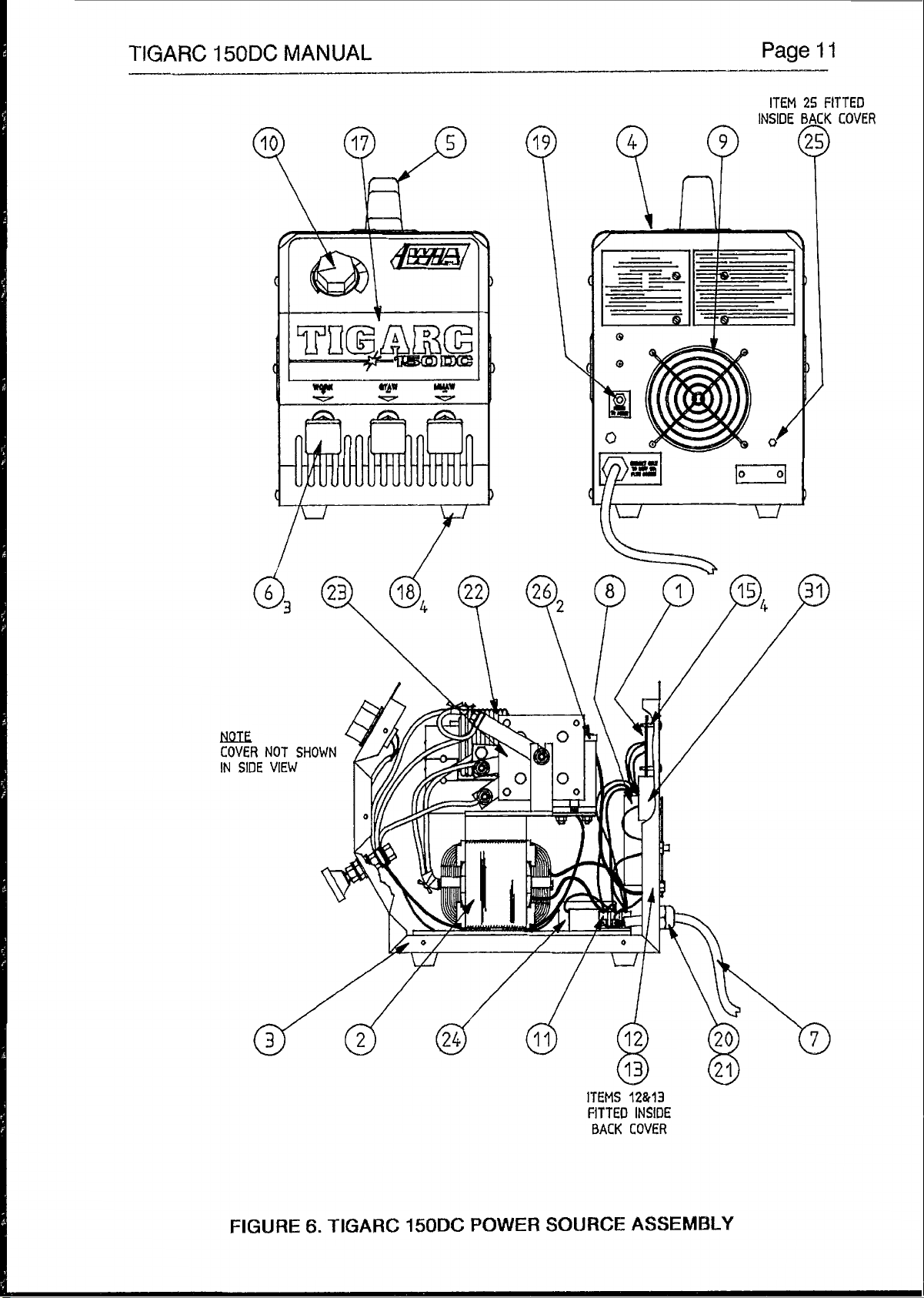
FIGURE
6.
TIGARC
150DC
POWER
ITEMS
FITTED
BACK
SOURCE
12&13
INSIDE
COVER
ASSEMBLY
Page 12

page
12
TIGARC
158DC
MANUAL
GTAW
ITEM
Includes
TORCH AND
#.............PART
1
.................
1
.
1
.............
1.2
..............
l
,3.
.............
1.4
..............
1.5
..............
-I
..............
2.....
............
3.................CKi5PCA..................Porch
4..........,......AA47-0/1
5..
...............
ACCESSORIES
#.....................DESCRIPTION
CK1512VR
.300M..
3OOH-13
3C332
3CB332
3A7
IBQVK
"fWNGTH2.4
.......................
.......................
.......................
.....................
...........................
.......................
..................
HA101-185
................
GTAW
Medium
Heatshield
Collet
Collet
Alumina
Gas
..............
................
2.4mrn
Gas
Gas
Torch,
bac
kcap
body
Nozzle
Valve
diam.
Terminal
Hose
Regulator
Assembly
Rigid
2%
Thoriated
Adaptor
and
Tungsten
ftowgauge
FIGURE
7.
GTAW
TORCH
AND
ACCESSORIES
Page 13

TIGARC
9.
SAFE
150DC
MANUAL
PRACTICES
WHEN USING WELDING
EQUIPMENT
Page
l3
These notes are provided in the interests
to
only as a basic guide
the Standards Association of Australia, also various State Electricity Authorities, Departments of Labour and
Industry or Mines Department and other Local Health or Safety Inspection Authorities may have additional
requirements. WTlA Technical Note TN7-98
welding.
EYE
PROTECTION
NEVER
with side shields underneath, with appropriate filter lenses protected by clear cover lens. This is a MUST for
welding, cutting, and chipping
lens when broken, pitted, or spattered.
LOOK
Amps
0-100
700-150
150-200
200-300
300-400
400-500
500
+
Safe Working Habits. A full list of Standards pertaining
AT AN ARC WITHOUT PROTECTION. Wear a helmet with safety goggles or glasses
to
protect the eyes from radiant energy and flying metal. Replace the cover
Recommended
TIG MMAW MIG Pulsed MIG
.............
...................................................
10
..................
.........
l1
..................
.........
12
..................
.........
13..
................
.........
14
..................
............................
"
"
shade
9
10
10-11
1 1
12
13
"
of
improving operator safety. They should be considered
also
provides a comprehensive guide
filter
lens.
...................
.................
............
.................
.................
.................
10
10
11-12
12-1 3
13
14
14
.................
.................
............
............
.................
.................
.................
12-13
12-13
12-13
12-1
14
14
14
3
to
industry is available from
to
safe practices in
BURN PROTECTION.
The welding arc is intense and visibly bright.
clothing, reflect from light-coloured surfaces, and burn the skin and eyes. Burns resulting from gas-shielded
arcs resemble acute sunburn, but can be more severe and painful.
Wear protective clothing
collar and pocket flaps, and wear cuffless trousers
Avoid oily or greasy clothing.
pieces should never be handled without gloves.
Ear plugs should be worn when welding in overhead positions or in a confined space. A hard hat
should be worn when others are working overhead.
Flammable hair preparations should not be used by persons intending to weld or cut.
TOXIC
vapours, heat, or oxygen depletion that welding or cutting may produce. NEVER ventilate with oxygen.
produce harmful concentrations of toxic fumes. Adequate local exhaust ventilation must be used, or each
person in the area as well as the operator must wear an air-supplied respirator. For beryllium, both must be
used.
removed from the work surface, the area is well ventilated, or the operator wears an air-supplied respirator.
respirator.
FUMES.
Adequate ventilation with air is essential. Severe discomfort, illness or death can result from fumes,
Lead, cadmium, zinc, mercury, and beryllium bearing and similar materials when welded or cut may
Metals coated with or containing materials that emit fumes should not be heated unless coating is
Work in a confined space only while it is being ventilated and, if necessary, while wearing air-supplied
-
leather or heat resistant gloves, hat, and safety-toe boots. Button shirt
A
spark may ignite them.
Its
radiation can damage eyes, penetrate lightweight
to
avoid entry of sparks and slag.
Hot
metal such as electrode stubs and work
Page 14

page
supplied respirator.
14
Work
in
a confined space
only
while
it
is being ventilated and,
TtGARC
if
necessary, while Wearing air-
15QDC
MANUAL
Vapours from chlorinated solvents can be decomposed by the heat of the arc (or flame)
PHOSGENE,
energy of the arc can also decompose trichlorethylene and perchlorethylene vapors to form
phosgene.
atmosphere or where the radiant energy can penetrate
amounts
FIRE
windows or doors, and through watl or floor openings, out of sight of the operator. Sparks and slag
can travel up to
particles that can cause short circuits.
to
work can not be moved, move combustibles at least
or protect against ignition with suitable and snug-fitting fire-resistant covers or shields.
and floor near work should be protected
durlng and for some time after welding or cutting
AND
Be
Keep equipment clean and operable, free
If
combustibles are present in the work area, do
an area free of combustibles. Avoid paint spray rooms, dip tanks, storage areas, ventilators.
Walls
A
person acting
a highly toxic gas, and
Do
not weld or cut where solvent vapors can be drawn into
of
trichlorethylene or percholorethylene.
lung
and eye irritating products. The ultra-violet (radiant)
the
welding
to
atmospheres containing even minute
EXPLOSION PREVENTION.
aware that flying sparks or falling slag can pass through cracks,
10
metres from the arc.
of
oil, grease, and (in electrical parts) of metallic
NOT
weld or cut. Move the work
10
metres away out
touching combustibles on opposite sides should not be welded on or cut. Walls, ceilings,
by
heat-resistant covers or shields.
as
Fire Watcher must be standing by with suitable fire extinguishing equipment
if;
along
of
reach of sparks and heat;
pipes, through
to
form
or
cutting
if
practicable,
If
the
U
Combustibles (including building construction) are within
U
Combustibles are further than
U
Openings (concealed or visible)
combustibles to sparks.
a
Combustibles adjacent
radiant or conducted heat.
is
After work
An
tank or drum which has contained combustibles can produce flammable vapors when
heated. Such a container must never be welded on or cut, unless
described
steam
followed by purging and inerting wlth nitrogen or carbon dioxide, and using protective equipment as
recommended In
Never weld
SHOCK
equipment can fatally shock a person whose body becomes a conductor. Ensure that the machine
correctly connected and earthed.
mobile or portable equlpment, regularly inspect condition of traillng power teads and connecting
plugs. Repair or replace damaged leads.
in
or
caustic cleaning (or a solvent or water washing, dependlng on the combustible’s solubility),
Hollow castings or containers must be vented before weldlng or cutting. They can explode.
PREVENTION.
Exposed conductors or other bare metal
done, check that area
AS.1674-1974,
AS.1674-1974.
or
cut where the air may contain flammable dust, gas, or liquid vapours.
the
S.A.A.
Water-filling just below worktng level may substitute for inerting.
10
metres but can be ignited
in
floors or walls within
to
walls, ceilings, roofs,
is
free
of
sparks, glowing embers, and flames.
Cutting and Welding Safety Code. This includes a thorough
in
the welding circuit, or ungrounded electrlcally alive
If
unsure have machine installed by a qualified electricfan. On
or
10
metres.
by
sparks.
10
metres may expose
metal partitions can be ignited by
it
has first been cleaned as
is
Fully insulated electrode holders should be used.
Fully insulated lock-type connectors should be used to join welding cable lengths.
Terminals and other exposed parts of electrical unlts should have insulated knobs or covers
secured before operation.
Do
not use holders with protruding screws.
 Loading...