

Page 1
INSTRUCTION MANUAL
PHONE : (+44) 0845 130 7757
Email: [email protected]
Website: www.weldability-sif.com
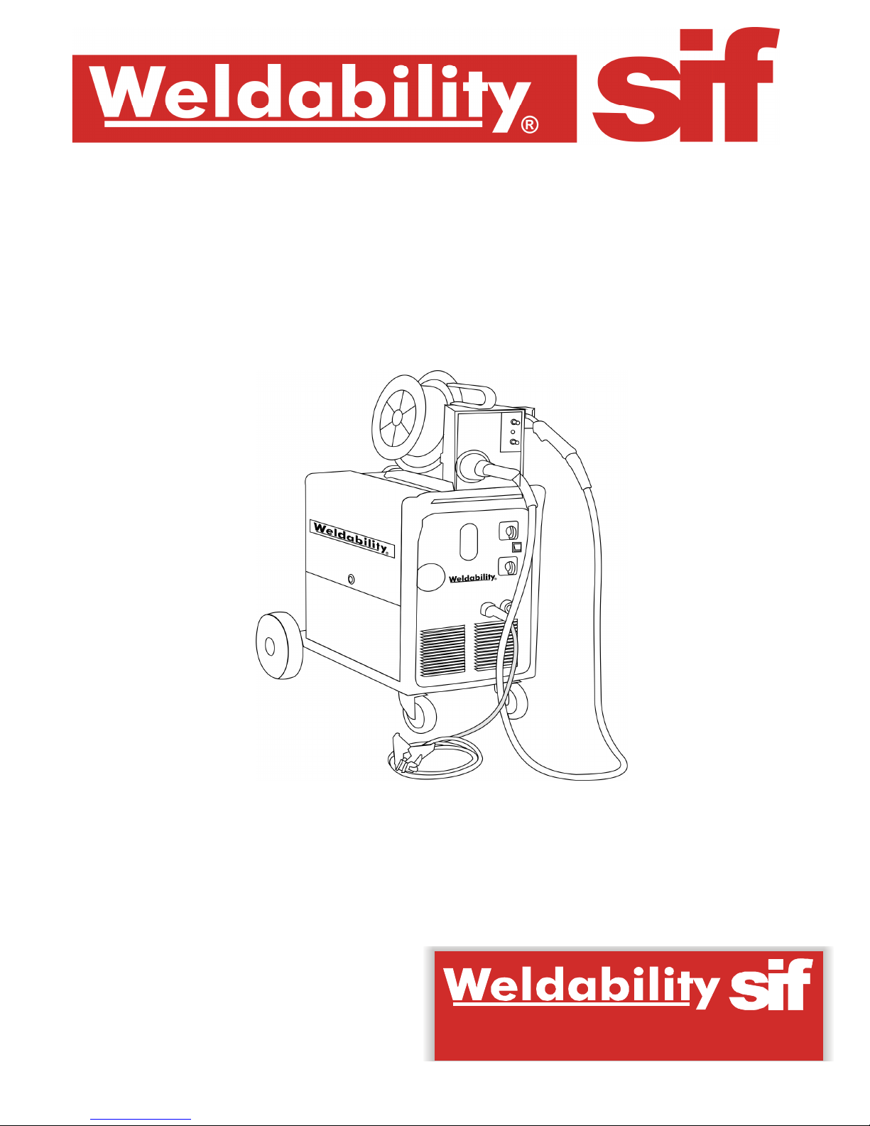
WELDABILITY MIG400E MACHINE
®
FAX : (+44) 01462 482202
Page 2
H A VESZÉLY, KÖTELEZETTSÉG ÉS TILTÁS JELZÉSEINEK FELIRATAI.
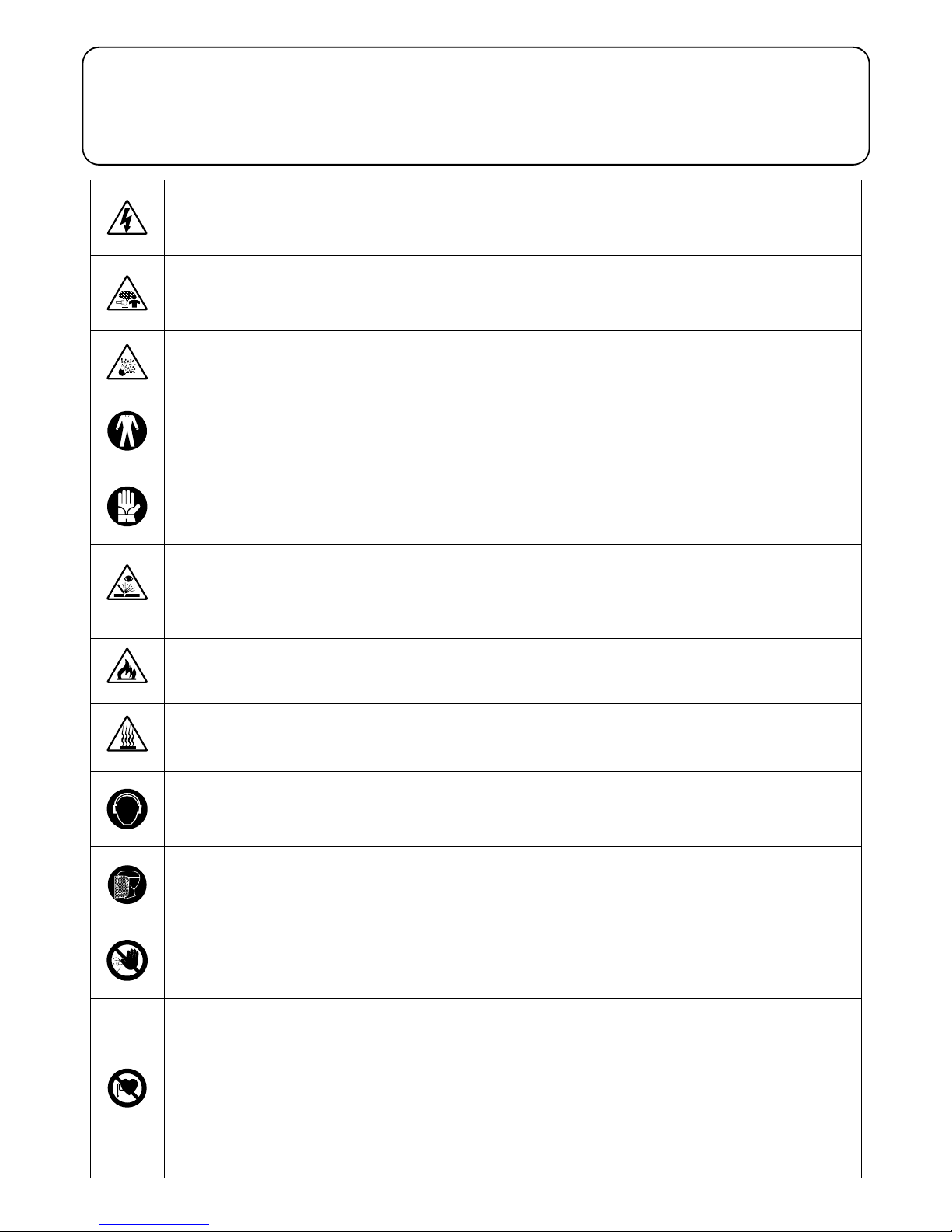
GB EXPLANATION OF DANGER, MANDATORY AND PROHIBITION SIGNS.
RO LEGENDĂ INDICATOARE DE AVERTIZARE A PERICOLELOR, DE OBLIGARE ŞI
I LEGENDA SEGNALI DI PERICOLO, D’OBBLIGO E DIVIETO.
DE INTERZICERE.
F LÉGENDE SIGNAUX DE DANGER, D'OBLIGATION ET D'INTERDICTION.
PL OBJAŚNIENIA ZNAKÓW OSTRZEGAWCZYCH, NAKAZU I ZAKAZU.
D LEGENDE DER GEFAHREN-, GEBOTS- UND VERBOTSZEICHEN.
CZ VYSVĚTLIVKY K SIGNÁLŮM NEBEZPEČÍ, PŘÍKAZŮM A ZÁKAZŮM.
E LEYENDA SEÑALES DE PELIGRO, DE OBLIGACIÓN Y PROHIBICIÓN.
SK VYSVETLIVKY K SIGNÁLOM NEBEZPEČENSTVA, PRÍKAZOM A ZÁKAZOM.
P LEGENDA DOS SINAIS DE PERIGO, OBRIGAÇÃO E PROIBIDO.
SI LEGENDA SIGNALOV ZA NEVARNOST, ZA PREDPISANO IN PREPOVEDANO.
NL LEGENDE SIGNALEN VAN GEVAAR, VERPLICHTING EN VERBOD.
HR/SCG LEGENDA OZNAKA OPASNOSTI, OBAVEZA I ZABRANA.
DK OVERSIGT OVER FARE, PLIGT OG FORBUDSSIGNALER.
LT PAVOJAUS, PRIVALOMŲJŲ IR DRAUDŽIAMŲJŲ ŽENKLŲ PAAIŠKINIMAS.
SF VAROITUS, VELVOITUS, JA KIELTOMERKIT.
EE OHUD, KOHUSTUSED JA KEELUD.
N SIGNALERINGSTEKST FOR FARE, FORPLIKTELSER OG FORBUDT.
LV BĪSTAMĪBU, PIENĀKUMU UN AIZLIEGUMA ZĪMJU PASKAIDROJUMI.
S BILDTEXT SYMBOLER FÖR FARA, PÅBUD OCH FÖRBUD.
BG ЛЕГЕНДА НА ЗНАЦИТЕ ЗА ОПАСНОСТ, ЗАДЪЛЖИТЕЛНИ И ЗА ЗАБРАНА.
GR ΛΕΖΑΝΤΑ ΣΗΜΑΤΩΝ ΚΙΝΔΥΝΟΥ, ΥΠΟΧΡΕΩΣΗΣ ΚΑΙ ΑΠΑΓΟΡΕΥΣΗΣ.
RU ЛЕГЕНДА СИМВОЛОВ БЕЗОПАСНОСТИ, ОБЯЗАННОСТИ И ЗАПРЕТА.
DANGER OF ELECTRIC SHOCK - PERICOLO SHOCK ELETTRICO - RISQUE DE CHOC ÉLECTRIQUE - STROMSCHLAGGEFAHR - PELIGRO DESCARGA ELÉCTRICA PERIGO DE CHOQUE ELÉTRICO - GEVAAR ELEKTROSHOCK - FARE FOR ELEKTRISK STØD - SÄHKÖISKUN VAARA - FARE FOR ELEKTRISK STØT - FARA FÖR
ELEKTRISK STÖT - ΚΙΝΔΥΝΟΣ ΗΛΕΚΤΡΟΠΛΗΞΙΑΣ - ОПАСНОСТЬ ПОРАЖЕНИЯ ЭЛЕКТРИЧЕСКИМ ТОКОМ - ÁRAMÜTÉS VESZÉLYE - PERICOL DE ELECTROCUTARE
- NIEBEZPIECZEŃSTWO SZOKU ELEKTRYCZNEGO - NEBEZPEČÍ ZÁSAHU ELEKTRICKÝM PROUDEM - NEBEZPEČENSTVO ZÁSAHU ELEKTRICKÝM PRÚDOM NEVARNOST ELEKTRIČNEGA UDARA - OPASNOST STRUJNOG UDARA - ELEKTROS SMŪGIO PAVOJUS - ELEKTRILÖÖGIOHT - ELEKTROŠOKA BĪSTAMĪBA -
ОПАСНОСТ ОТ ТОКОВ УДАР.
DANGER OF WELDING FUMES - PERICOLO FUMI DI SALDATURA - DANGER FUMÉES DE SOUDAGE - GEFAHR DER ENTWICKLUNG VON RAUCHGASEN BEIM
SCHWEISSEN - PELIGRO HUMOS DE SOLDADURA - PERIGO DE FUMAÇAS DE SOLDAGEM - GEVAAR LASROOK - FARE P.G.A. SVEJSEDAMPE - HITSAUSSAVUJEN
VAARA - FARE FOR SVEISERØYK - FARA FÖR RÖK FRÅN SVETSNING - ΚΙΝΔΥΝΟΣ ΚΑΠΝΩΝ ΣΥΓΚΟΛΛΗΣΗΣ - ОПАСНОСТЬ ДЫМОВ СВАРКИ - HEGESZTÉS
KÖVETKEZTÉBEN KELETKEZETT FÜST VESZÉLYE - PERICOL DE GAZE DE SUDURĂ - NIEBEZPIECZEŃSTWO OPARÓW SPAWALNICZYCH - NEBEZPEČÍ
SVAŘOVACÍCH DÝMŮ - NEBEZPEČENSTVO VÝPAROV ZO ZVÁRANIA - NEVARNOST VARILNEGA DIMA - OPASNOST OD DIMA PRILIKOM VARENJA - SUVIRINIMO
DŪMŲ PAVOJUS - KEEVITAMISEL SUITSU OHT - METINĀŠANAS IZTVAIKOJUMU BĪSTAMĪBA - ОПАСНОСТ ОТ ПУШЕКА ПРИ ЗАВАРЯВАНЕ.
DANGER OF EXPLOSION - PERICOLO ESPLOSIONE - RISQUE D'EXPLOSION - EXPLOSIONSGEFAHR - PELIGRO EXPLOSIÓN - PERIGO DE EXPLOSÃO - GEVAAR
ONTPLOFFING - SPRÆNGFARE - RÄJÄHDYSVAARA - FARE FOR EKSPLOSJON - FARA FÖR EXPLOSION - ΚΙΝΔΥΝΟΣ ΕΚΡΗΞΗΣ - ОПАСНОСТЬ ВЗРЫВА -
ROBBANÁS VESZÉLYE - PERICOL DE EXPLOZIE - NIEBEZPIECZEŃSTWO WYBUCHU - NEBEZPEČÍ VÝBUCHU - NEBEZPEČENSTVO VÝBUCHU - NEVARNOST
EKSPLOZIJE - OPASNOST OD EKSPLOZIJE - SPROGIMO PAVOJUS - PLAHVATUSOHT - SPRĀDZIENBĪSTAMĪBA - ОПАСНОСТ ОТ ЕКСПЛОЗИЯ.
WEARING PROTECTIVE CLOTHING ISC OMPULSORY - OBBLIGO INDOSSARE INDUMENTI PROTETTIVI - PORT DES VÊTEMENTS DE PROTECTION OBLIGATOIRE -
DAS TRAGEN VON SCHUTZKLEIDUNG IST PFLICHT - OBLIGACIÓN DE LLEVAR ROPA DE PROTECCIÓN - OBRIGATÓRIO O USO DE VESTUÁRIO DE PROTEÇÃO VERPLICHT BESCHERMENDE KLEDIJ TE DRAGEN - PLIGT TIL AT ANVENDE BESKYTTELSESTØJ - SUOJAVAATETUKSEN KÄYTTÖ PAKOLLISTA - FORPLIKTELSE Å
BRUKE VERNETØY - OBLIGATORISKT ATT BÄRA SKYDDSPLAGG - ΥΠΟΧΡΕΩΣΗ ΝΑ ΦΟΡΑΤΕ ΠΡΟΣΤΑΤΕΥΤΙΚΑ ΕΝΔΥΜΑΤΑ - ОБЯЗАННОСТЬ НАДЕВАТЬ
ЗАЩИТНУЮ ОДЕЖДУ - VÉDŐRUHA HASZNÁLATA KÖTELEZŐ - FOLOSIREA ÎMBRĂCĂMINTEI DE PROTECŢIE OBLIGATORIE - NAKAZ NOSZENIA ODZIE Y
OCHRONNEJ- POVINNÉ POUŽITÍ OCHRANNÝCH PROSTŘEDKŮ - POVINNÉ POUŽITIE OCHRANNÝCH PROSTRIEDKOV - OBVEZNO OBLECITE ZAŠČITNA OBLAČILA OBAVEZNO KORIŠTENJE ZAŠTITNE ODJEĆE - PRIVALOMA DĖVĖTI APSAUGINĘ APRANGĄ - KOHUSTUSLIK KANDA KAITSERIIETUST - PIENĀKUMS ĢĒRBT
AIZSARGTĒRPUS - ЗАДЪЛЖИТЕЛНО НОСЕНЕ НА ПРЕДПАЗНО ОБЛЕКЛО.
Ż
WEARING PROTECTIVE GLOVES IS COMPULSORY - OBBLIGO INDOSSARE GUANTI PROTETTIVI - PORT DES GANTS DE PROTECTION OBLIGATOIRE - DAS TRAGEN
VON SCHUTZHANDSCHUHEN IST PFLICHT - OBLIGACIÓN DE LLEVAR GUANTES DE PROTECCIÓN - OBRIGATÓRIO O USO DE LUVAS DE SEGURANÇA - VERPLICHT
BESCHERMENDE HANDSCHOENEN TE DRAGEN - PLIGT TIL AT BRUGE BESKYTTELSESHANDSKER - SUOJAKÄSINEIDEN KÄYTTÖ PAKOLLISTA - FORPLIKTELSE Å
BRUKE VERNEHANSKER - OBLIGATORISKT ATT BÄRA SKYDDSHANDSKAR - ΥΠΟΧΡΕΩΣΗ ΝΑ ΦΟΡΑΤΕ ΠΡΟΣΤΑΤΕΥΤΙΚΑ ΓΑΝΤΙΑ -
ОБЯЗАННОСТЬ НАДЕВАТЬ
VÉDŐKESZTYŰ HASZNÁLATA KÖTELEZŐ - FOLOSIREA MĂNUŞILOR DE PROTECŢIE OBLIGATORIE - NAKAZ NOSZENIA RĘKAWIC
ЗАЩИТНЫЕ ПЕРЧАТКИ -
OCHRONNYCH - POVINNÉ POUŽITÍ OCHRANNÝCH RUKAVIC - POVINNÉ POUŽITIE OCHRANNÝCH RUKAVÍC - OBVEZNO NADENITE ZAŠČITNE ROKAVICE OBAVEZNO KORIŠTENJE ZAŠTITNIH RUKAVICA - PRIVALOMA MŪVĖTI APSAUGINES PIRŠTINES - KOHUSTUSLIK KANDA KAITSEKINDAID - PIENĀKUMS ĢĒRBT
AIZSARGCIMDUS - ЗАДЪЛЖИТЕЛНО НОСЕНЕ НА ПРЕДПАЗНИ РЪКАВИЦИ.
DANGER OF ULTRAVIOLET RADIATION FROM WELDING - PERICOLO RADIAZIONI ULTRAVIOLETTE DA SALDATURA - DANGER RADIATIONS ULTRAVIOLETTES DE
SOUDAGE - GEFAHR ULTRAVIOLETTER STRAHLUNGEN BEIM SCHWEISSEN - PELIGRO RADIACIONES ULTRAVIOLETAS - PERIGO DE RADIAÇÕES ULTRAVIOLETAS
DE SOLDADURA - GEVAAR ULTRAVIOLET STRALEN VAN HET LASSEN - FARE FOR ULTRAVIOLETTE SVEJSESTRÅLER - HITSAUKSEN AIHEUTTAMAN
ULTRAVIOLETTISÄTEILYN VAARA - FARE FOR ULTRAFIOLETT STRÅLNING UNDER SVEISINGSPROSEDYREN - FARA FÖR ULTRAVIOLETT STRÅLNING FRÅN
SVETSNING - ΚΙΝΔΥΝΟΣ ΥΠΕΡΙΩΔΟΥΣ ΑΚΤΙΝΟΒΟΛΙΑΣ ΑΠΟ ΣΥΓΚΟΛΛΗΣΗ - ОПАСНОСТЬ УЛЬТРАФИОЛЕТОВОГО ИЗЛУЧЕНИЯ СВАРКИ - HEGESZTÉS
KÖVETKEZTÉBEN LÉTREJÖTT IBOLYÁNTÚLI SUGÁRZÁS VESZÉLYE - PERICOL DE RADIAŢII ULTRAVIOLETE DE LA SUDURĂ - NIEBEZPIECZEŃSTWO
PROMIENIOWANIA NADFIOLETOWEGO PODCZAS SPAWANIA - NEBEZPEČÍ ULTRAFIALOVÉHO ZÁŘENÍ ZE SVAŘOVÁNÍ Í - NEBEZPEČENSTVO ULTRAFIALOVÉHO
ŽIARENIA ZO ZVÁRANIA - NEVARNOST SEVANJA ULTRAVIJOLIČNIH ŽARKOV ZARADI VARJENJA - OPASNOST OD ULTRALJUBIČASTIH ZRAKA PRILIKOM VARENJA
- ULTRAVIOLETINIO SPINDULIAVIMO SUVIRINIMO METU PAVOJUS - KEEVITAMISEL ERALDUVA ULTRAVIOLETTKIIRGUSEOHT - METINĀŠANAS ULTRAVIOLETĀ
IZSTAROJUMA BĪSTAMĪBA - ОПАСНОСТ ОТ УЛТРАВИОЛЕТОВО ОБЛЪЧВАНЕ ПРИ ЗАВАРЯВАНЕ.
WEARING A PROTECTIVE MASK IS COMPULSORY - OBBLIGO USARE MASCHERA PROTETTIVA - PORT DU MASQUE DE PROTECTION OBLIGATOIRE - DER
GEBRAUCH EINER SCHUTZMASKE IST PFLICHT - OBLIGACIÓN DE USAR MÁSCARA DE PROTECCIÓN - OBRIGATÓRIO O USO DE MÁSCARA DE PROTEÇÃO VERPLICHT GEBRUIK VAN BESCHERMEND MASKER - PLIGT TIL AT ANVENDE BESKYTTELSESMASKE - SUOJAMASKIN KÄYTTÖ PAKOLLISTA - FORPLIKTELSE Å
BRUKE VERNEBRILLER - OBLIGATORISKT ATT BÄRA SKYDDSMASK - ΥΠΟΧΡΕΩΣΗ ΝΑ ΦΟΡΑΤΕ ΠΡΟΣΤΑΤΕΥΤΙΚΗ ΜΑΣΚΑ - ОБЯЗАННОСТЬ ПОЛЬЗОВАТЬСЯ
ЗАЩИТНОЙ МАСКОЙ - VÉDŐMASZK HASZNÁLATA KÖTELEZŐ - FOLOSIREA MĂŞTII DE PROTECŢIE OBLIGATORIE - NAKAZ UŻYWANIA MASKI OCHRONNEJ -
POVINNÉ POUŽITÍ OCHRANNÉHO ŠTÍTU - POVINNÉ POUŽITIE OCHRANNÉHO ŠTÍTU - OBVEZNOST UPORABI ZAŠČITNE MASKE - OBAVEZNO KORIŠTENJE
ZAŠTITNE MASKE - PRIVALOMA UŽSIDĖTI APSAUGINĘ KAUKĘ - KOHUSTUSLIK KANDA KAITSEMASKI - PIENĀKUMS IZMANTOT AIZSARGMASKU -
ЗАДЪЛЖИТЕЛНО ИЗПОЛЗВАНЕ НА ПРЕДПАЗНА ЗАВАРЪЧНА МАСКА.
USERS OF VITAL ELECTRICAL AND ELECTRONIC DEVICES MUST NOT USE THE WELDING MACHINE - VIETATO L’USO DELLA SALDATRICE AI PORTATORI DI
APPARECCHIATURE ELETTRICHE ED ELETTRONICHE VITALI - UTILISATION DU POSTE DE SOUDAGE INTERDIT AUX PORTEURS D'APPAREILS ÉLECTRIQUES ET
ÉLECTRONIQUES MÉDICAUX - TRÄGERN LEBENSERHALTENDER ELEKTRISCHER UND ELEKTRONISCHER GERÄTE IST DER GEBRAUCH DER
SCHWEISSMASCHINE UNTERSAGT - PROHIBIDO EL USO DE LA SOLDADORA A LOS PORTADORES DE APARATOS ELÉCTRICOS Y ELECTRÓNICOS VITALES - È
PROIBIDO O USO DA MÁQUINA DE SOLDA POR PORTADORES DE APARELHAGENS ELÉTRICAS E ELETRÔNICAS VITAIS - HET GEBRUIK VAN DE LASMACHINE IS
VERBODEN AAN DE DRAGERS VAN VITALE ELEKTRISCHE EN ELEKTRONISCHE APPARATUUR - DET ER FORBUDT FOR DEM, DER ANVENDER LIVSVIGTIGT
ELEKTRISK OG ELEKTRONISK APPARATUR, AT BENYTTE SVEJSEMASKINEN - HITSAUSKONEEN KÄYTTÖ KIELLETTY HENKILÖILLE, JOILLA ON ELIMISTÖÖN
ASENNETTU SÄHKÖINEN TAI ELEKTRONINEN LAITE - FORBUDT Å BRUKE SVEISEBRENNEREN FOR PERSONER SOM BRUKER LIVSVIKTIGE ELEKTRISKE OG
ELEKTRONISKE APPARATER - FÖRBJUDET FÖR PERSONER SOM BÄR ELEKTRISKA OCH ELEKTRONISKA LIVSUPPEHÅLLANDE APPARATER ATT ANVÄNDA
SVETSEN - ΑΠΑΓΟΡΕΥΕΤΑΙ Η ΧΡΗΣΗ ΤΟΥ ΣΥΓΚΟΛΛΗΤΗ ΣΕ ΑΤΟΜΑ ΠΟΥ ΦΕΡΟΥΝ ΗΛΕΚΤΡΙΚΕΣ ΚΑΙ ΗΛΕΚΤΡΟΝΙΚΕΣ ΣΥΣΚΕΥΕΣ ΖΩΤΙΚΗΣ ΣΗΜΑΣΙΑΣ -
ЗАПРЕЩАЕТСЯ ИСПОЛЬЗОВАНИЕ СВАРОЧНОГО АППАРАТА ЛИЦАМ С ЖИЗНЕННОВАЖНОЙ ЭЛЕКТРИЧЕСКОЙ И ЭЛЕКТРОННОЙ АППАРАТУРЫ - TILOS A
HEGESZTŐGÉP HASZNÁLATA MINDAZOK SZÁMÁRA, AKIK SZERVEZETÉBEN ÉLETFENNTARTÓ ELEKTROMOS VAGY ELEKTRONIKUS KÉSZÜLEK VAN BEÉPÍTVE-
SE INTERZICE FOLOSIREA APARATULUI DE SUDURĂ DE CĂTRE PERSOANE PURTĂTOARE DE APARATURĂ ELECTRICĂ ŞI ELECTRONICĂ VITALE - ZABRONIONE
JEST UŻYWANIE SPAWARKI OSOBOM STOSUJĄCYM URZĄDZENIA ELEKTRYCZNE I ELEKTRONICZNE WSPOMAGAJĄCE FUNKCJE ŻYCIOWE - ZÁKAZ POUŽITÍ
SVAŘOVACÍHO PŘÍSTROJE NOSITELŮM ELEKTRICKÝCH A ELEKTRONICKÝCH ŽIVOTNĚ DŮLEŽITÝCH ZAŘÍZENÍ - ZÁKAZ POUŽÍVANIA ZVÁRACIEHO PRÍSTROJA
OSOBÁM POUŽÍVAJÚCIM ELEKTRICKÉ A ELEKTRONICKÉ ŽIVOTNE DÔLEŽITÉ ZARIADENIA - PREPOVEDANA UPORABA VARILNE NAPRAVE ZA OSEBE, KI
UPORABLJAJO ELEKTRIČNE IN ELEKTRONSKE ŽIVLJENJSKO POMEMBNE NAPRAVE - ZABRANJENO JE KORIŠTENJE STROJA ZA VARENJE NOSITELJIMA
ELEKTRIČNIH I ELEKTRONSKIH APARATA - ASMENIMS, SU GYVYBIŠKAI SVARBIAIS ELEKTRINIAIS AR ELEKTRONINIAIS PRIETAISAIS, SUVIRINIMO APARATU
NAUDOTIS DRAUDŽIAMA - KEEVITUSAPARAADI KASUTAMINE ON KEELATUD ISIKUTELE, KES KANNAVAD MEDITSIINILISI ELEKTRIINSTRUMENTI JA
ELUSTAMISSEADMEID - ELEKTRISKO VAI ELEKTRONISKO MEDICĪNISKO IERĪČU LIETOTĀJIEM IR AIZLIEGTS IZMANTOT METINĀŠANAS APARĀTU - ЗАБРАНЕНО Е
ИЗПОЛЗВАНЕТО НА ЕЛЕКТРОЖЕНА ОТ ЛИЦА - НОСИТЕЛИ НА ЕЛЕКТРИЧЕСКИ И ЕЛЕКТРОННИ МЕДИЦИНСКИ УСТРОЙСТВА.
DANGER OF FIRE - PERICOLO INCENDIO - RISQUE D'INCENDIE - BRANDGEFAHR - PELIGRO DE INCENDIO - PERIGO DE INCÊNDIO - GEVAAR VOOR BRAND BRANDFARE - TULIPALON VAARA - BRANNFARE - BRANDRISK - ΚΙΝΔΥΝΟΣ ΠΥΡΚΑΓΙΑΣ - ОПАСНОСТЬ ПОЖАРА - TŰZVESZÉLY - PERICOL DE INCENDIU -
NIEBEZPIECZEŃSTWO POŻARU - NEBEZPEČÍ POŽÁRU - NEBEZPEČENSTVO POŽIARU - NEVARNOST POŽARA - OPASNOST OD POŽARA - GAISRO PAVOJUS TULEOHT - UGUNSGRĒKA BĪSTAMĪBA - ОПАСНОСТ ОТ ПОЖАР.
DANGER OF BURNS - PERICOLO DI USTIONI - RISQUE DE BRÛLURES - VERBRENNUNGSGEFAHR - PELIGRO DE QUEMADURAS - PERIGO DE QUEIMADURAS GEVAAR VOOR BRANDWONDEN - FARE FOR FORBRÆNDINGER - PALOVAMMOJEN VAARA - FARE FOR FORBRENNINGER - RISK FÖR BRÄNNSKADA - ΚΙΝΔΥΝΟΣ
ΕΓΚΑΥΜΑΤΩΝ - ОПАСНОСТЬ ОЖОГОВ - ÉGÉSI SÉRÜLÉS VESZÉLYE - PERICOL DE ARSURI - NIEBEZPIECZEŃSTWO OPARZEŃ - NEBEZPEČÍ POPÁLENIN -
NEBEZPEČENSTVO POPÁLENÍN - NEVARNOST OPEKLIN - OPASNOST OD OPEKLINA - NUSIDEGINIMO PAVOJUS - PÕLETUSHAAVADE SAAMISE OHT - APDEGUMU
GŪŠANAS BĪSTAMĪBA - ОПАСНОСТ ОТ ИЗГАРЯНИЯ.
NO ENTRY FOR UNAUTHORISED PERSONNEL - DIVIETO DI ACCESSO ALLE PERSONE NON AUTORIZZATE - ACCÈS INTERDIT AUX PERSONNES NON AUTORISÉES UNBEFUGTEN PERSONEN IST DER ZUTRITT VERBOTEN - PROHIBIDO EL ACCESO A PERSONAS NO AUTORIZADAS - PROIBIÇÃO DE ACESSO ÀS PESSOAS NÃO
AUTORIZADAS - TOEGANGSVERBOD VOOR NIET GEAUTORISEERDE PERSONEN - ADGANG FORBUDT FOR UVEDKOMMENDE - PÄÄSY KIELLETTY ASIATTOMILTA PERSONER SOM IKKE ER AUTORISERTE MÅ IKKE HA ADGANG TIL APPARATEN - TILLTRÄDE FÖRBJUDET FÖR ICKE AUKTORISERADE PERSONER - ΑΠΑΓΟΡΕΥΣΗ
ΠΡΟΣΒΑΣΗΣ ΣΕ ΜΗ ΕΠΙΤΕΤΡΑΜΕΝΑ ΑΤΟΜΑ - ЗАПРЕТ ДЛЯ ДОСТУПА ПОСТОРОННИХ ЛИЦ - FEL NEM JOGOSÍTOTT SZEMÉLYEK SZÁMÁRA TILOS A BELÉPÉS -
ACCESUL PERSOANELOR NEAUTORIZATE ESTE INTERZIS - ZAKAZ DOSTĘPU OSOBOM NIEUPOWAŻNIONYM - DOSTOP PREPOVEDAN NEPOOBLAŠČENIM
OSEBAM - ZÁKAZ VSTUPU NEPOVOLANÝM OSOBÁM - ZABRANA PRISTUPA NEOVLAŠTENIM OSOBAMA - PAŠALINIAMS ĮEITI DRAUDŽIAMA - SELLEKS
VOLITAMATA ISIKUTEL ON TÖÖALAS VIIBIMINE KEELATUD - NEPIEDEROŠĀM PERSONĀM IEEJA AIZLIEGTA - ЗАБРАНЕН Е ДОСТЪПЪТ НА НЕУПЪЛНОМОЩЕНИ
ЛИЦА.
USE OF EAR PROTECTORS IS COMPULSORY - OBBLIGO PROTEZIONE DELL’UDITO - PROTECTIONS DE L’OUÏE OBLIGATOIRES - DAS TRAGEN EINES
GEHÖRSCHUTZES IST PFLICHT - OBLIGACIÓN DE PROTECCIÓN DEL OÍDO - OBRIGAÇÃO DE PROTECÇÃO DOS OUVIDOS - OORBESCHERMING VERPLICHT - PLIGT
TIL AT ANVENDE HØREVÆRN - KUULON SUOJAUSPAKKO - DU MÅ HA PÅ DIG HØRSELVERN- HÖRSELN MÅSTE SKYDDAS - ΥΠΟΧΡΕΩΣΗ ΠΡΟΣΤΑΣΙΑΣ ΑΚΟΗΣ -
ОБЯЗАТЕЛЬНАЯ ЗАЩИТА ОРГАНОВ СЛУХА - HALLÁSVÉDELEM KÖTELEZŐ - PROTECŢIA AUZULUI OBLIGATORIE - NAKAZ OCHRONY SŁUCHU - POVINNOST
OCHRANY SLUCHU - POVINNÁ OCHRANA SLUCHU - OBVEZNA UPORABA GLUŠNIKOV - OBAVEZNA ZAŠTITA SLUHA - PRIVALOMOS APSAUGOS PRIEMONĖS
KLAUSOS ORGANAMS - KOHUSTUSLIK ON KANDA KUULMISKAITSEVAHENDEID - PIENĀKUMS AIZSARGĀT DZIRDES ORGĀNUS - ЗАДЪЛЖИТЕЛНО ДА СЕ
ПОЛЗВАТ ПРЕДПАЗНИ СРЕДСТВА ЗА СЛУХА.
- 2 -
Page 3
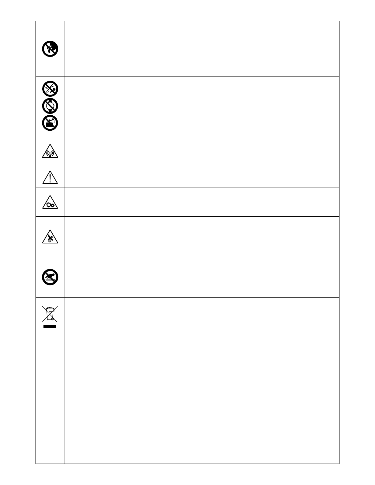
PEOPLE WITH METAL PROSTHESES ARE NOT ALLOWED TO USE THE MACHINE - VIETATO L'USO DELLA MACCHINA AI PORTATORI DI PROTESI METALLICHE UTILISATION INTERDITE DE LA MACHINE AUX PORTEURS DE PROTHÈSES MÉTALLIQUES - TRÄGERN VON METALLPROTHESEN IST DER UMGANG MIT DER
MASCHINE VERBOTEN - PROHIBIDO EL USO DE LA MÁQUINA A LOS PORTADORES DE PRÓTESIS METÁLICAS - PROIBIDO O USO DA MÁQUINA AOS PORTADORES
DE PRÓTESES METÁLICAS - HET GEBRUIK VAN DE MACHINE IS VERBODEN AAN DE DRAGERS VAN METALEN PROTHESEN - DET ER FORBUDT FOR PERSONER
MED METALPROTESER AT BENYTTE MASKINEN - KONEEN KÄYTTÖ KIELLETTY METALLIPROTEESIEN KANTAJILTA - BRUK AV MASKINEN ER IKKE TILLATT FOR
PERSONER MED METALLPROTESER - FÖRBJUDET FÖR PERSONER SOM BÄR METALLPROTES ATT ANVÄNDA MASKINEN - ΑΠΑΓΟΡΕΥΕΤΑΙ Η ΧΡΗΣΗ ΤΗΣ
ΜΗΧΑΝΗΣ ΣΕ ΑΤΟΜΑ ΠΟΥ ΦΕΡΟΥΝ ΜΕΤΑΛΛΙΚΕΣ ΠΡΟΣΘΗΚΕΣ - ИСПОЛЬЗОВАНИЕ МАШИНЫ ЗАПРЕЩАЕТСЯ ЛЮДЯМ, ИМЕЮЩИМ МЕТАЛЛИЧЕСКИЕ
ПРОТЕЗЫ - TILOS A GÉP HASZNÁLATA FÉMPROTÉZIST VISELŐ SZEMÉLYEK SZÁMÁRA - SE INTERZICE FOLOSIREA MAŞINII DE CĂTRE PERSOANELE
PURTĂTOARE DE PROTEZE METALICE - ZAKAZ UŻYWANIA URZĄDZENIA OSOBOM STOSUJĄCYM PROTEZY METALOWE - ZÁKAZ POUŽITÍ STROJE NOSITELŮM
KOVOVÝCH PROTÉZ - ZÁKAZ POUŽITIA STROJA OSOBÁM S KOVOVÝMI PROTÉZAMI - PREPOVEDANA UPORABA STROJA ZA NOSILCE KOVINSKIH PROTEZ ZABRANJENA UPOTREBA STROJA OSOBAMA KOJE NOSE METALNE PROTEZE - SU SUVIRINIMO APARATU DRAUDŽIAMA DIRBTI ASMENIMS, NAUDOJANTIEMS
METALINIUS PROTEZUS - SEADET EI TOHI KASUTADA ISIKUD, KES KASUTAVAD METALLPROTEESE - CILVĒKIEM AR METĀLA PROTĒZĒM IR AIZLIEGTS LIETOT
IERĪCI - ЗАБРАНЕНА Е УПОТРЕБАТА НА МАШИНАТА ОТ НОСИТЕЛИ НА МЕТАЛНИ ПРОТЕЗИ.
DO NOT WEAR OR CARRY METAL OBJECTS, WATCHES OR MAGNETISED CARDS - VIETATO INDOSSARE OGGETTI METALLICI, OROLOGI E SCHEDE MAGNETICHE INTERDICTION DE PORTER DES OBJETS MÉTALLIQUES, MONTRES ET CARTES MAGNÉTIQUES - DAS TRAGEN VON METALLOBJEKTEN, UHREN UND
MAGNETKARTEN IST VERBOTEN - PROHIBIDO LLEVAR OBJETOS METÁLICOS, RELOJES, Y TARJETAS MAGNÉTICAS - PROIBIDO VESTIR OBJECTOS METÁLICOS,
RELÓGIOS E FICHAS MAGNÉTICAS - HET IS VERBODEN METALEN VOORWERPEN, UURWERKEN EN MAGNETISCHE FICHES TE DRAGEN - FORBUD MOD AT BÆRE
METALGENSTANDE, URE OG MAGNETISKE KORT - METALLISTEN ESINEIDEN, KELLOJEN JA MAGNEETTIKORTTIEN MUKANA PITÄMINEN KIELLETTY - FORBUDT Å
HA PÅ SEG METALLFORMÅL, KLOKKER OG MAGNETISKE KORT - FÖRBJUDET ATT BÄRA METALLFÖREMÅL, KLOCKOR OCH MAGNETKORT - ΑΠΑΓΟΡΕΥΕΤΑΙ ΝΑ
ΦΟΡΑΤΕ ΜΕΤΑΛΛΙΚΑ ΑΝΤΙΚΕΙΜΕΝΑ, ΡΟΛΟΓΙΑ ΚΑΙ ΜΑΓΝΗΤΙΚΕΣ ΠΛΑΚΕΤΕΣ - ЗАПРЕЩАЕТСЯ НОСИТЬ МЕТАЛЛИЧЕСКИЕ ПРЕДМЕТЫ, ЧАСЫ ИЛИ МАГНИТНЫЕ
ПЛАТЫЮ - TILOS FÉMTÁRGYAK, KARÓRÁK VISELETE ÉS MÁGNESES KÁRTYÁK MAGUKNÁL TARTÁSA - ESTE INTERZISĂ PURTAREA OBIECTELOR METALICE, A
CEASURILOR ŞI A CARTELELOR MAGNETICE - ZAKAZ NOSZENIA PRZEDMIOTÓW METALOWYCH, ZEGARKÓW I KART MAGNETYCZNYCH - ZÁKAZ NOŠENÍ
KOVOVÝCH PŘEDMĚTŮ, HODINEK A MAGNETICKÝCH KARET - ZÁKAZ NOSENIA KOVOVÝCH PREDMETOV, HODINIEK A MAGNETICKÝCH KARIET - PREPOVEDANO
NOŠENJE KOVINSKIH PREDMETOV, UR IN MAGNETNIH KARTIC - ZABRANJENO NOŠENJE METALNIH PREDMETA, SATOVA I MAGNETSKIH ČIPOVA - DRAUDŽIAMA
PRIE SAVĘS TURĖ TI METALINIŲ DAIKTŲ, LAIKRODŽIŲ AR MAGNETINIŲ PLOKŠTELIŲ - KEELATUD ON KANDA METALLESEMEID, KELLASID JA MAGENTKAARTE -
IR AIZLIEGTS VILKT METĀLA PRIEKŠMETUS, PULKSTEŅUS UN ŅEMT LĪDZI MAGNĒTISKĀS KARTES - ЗАБРАНЕНО Е НОСЕНЕТО НА МЕТАЛНИ ПРЕДМЕТИ,
ЧАСОВНИЦИ И МАГНИТНИ СХЕМИ.
DANGER OF NON-IONISING RADIATION - PERICOLO RADIAZIONI NON IONIZZANTI - DANGER RADIATIONS NON IONISANTES - GEFAHR NICHT IONISIERENDER
STRAHLUNGEN - PELIGRO RADIACIONES NO IONIZANTES - PERIGO DE RADIAÇÕES NÃO IONIZANTES - GEVAAR NIET IONISERENDE STRALEN - FARE FOR IKKEIONISERENDE STRÅLER - IONISOIMATTOMAN SÄTEILYN VAARA - FARE FOR UJONISERT STRÅLNING - FARA FÖR ICKE JONISERANDE - ΚΙΝΔΥΝΟΣ ΜΗ
ΙΟΝΙΖΟΝΤΩΝ ΑΚΤΙΝΟΒΟΛΙΩΝ - ОПАСНОСТЬ НЕ ИОНИЗИРУЮЩЕЙ РАДИАЦИИ - NEM INOGEN SUGÁRZÁS VESZÉLYE - PERICOL DE RADIAŢII NEIONIZANTE -
ZAGROŻENIE PROMIENIOWANIEM NIEJONIZUJĄCYM - NEBEZPEČÍ NEIONIZUJÍCÍHO ZÁŘENÍ - NEBEZPEČENSTVO NEIONIZUJÚCEHO ZARIADENIA - NEVARNOST
NEJONIZIRANEGA SEVANJA - OPASNOST NEJONIZIRAJUĆIH ZRAKA - NEJONIZUOTO SPINDULIAVIMO PAVOJUS - MITTEIONISEERITUDKIIRGUSTE OHT NEJONIZĒJOŠA IZSTAROJUMA BĪSTAMĪBA - ОПАСТНОСТ ОТ НЕ ЙОНИЗИРАНО ОБЛЪЧВАНЕ.
GENERAL HAZARD - PERICOLO GENERICO - DANGER GÉNÉRIQUE - GEFAHR ALLGEMEINER ART - PELIGRO GENÉRICO - PERIGO GERAL - ALGEMEEN GEVAAR ALMEN FARE - YLEINEN VAARA - GENERISK FARE STRÅLNING - ALLMÄN FARA - ΓΕΝΙΚΟΣ ΚΙΝΔΥΝΟΣ - ОБЩАЯ ОПАСНОСТЬ - ÁLTALÁNOS VESZÉLY - PERICOL
GENERAL - OGÓLNE NIEBEZPIECZEŃSTWO - VŠEOBECNÉ NEBEZPEČÍ -VŠEOBECNÉ NEBEZPEČENSTVO - SPLOŠNA NEVARNOST - OPĆA OPASNOST - BENDRAS
PAVOJUS - ÜLDINE OHT - VISPĀRĪGA BĪSTAMĪBA - ОБЩИ ОПАСТНОСТИ.
WARNING: MOVING PARTS - ATTENZIONE ORGANI IN MOVIMENTO - ATTENTION ORGANES EN MOUVEMENT - VORSICHT BEWEGUNGSELEMENTE - ATENCIÓN
ÓRGANOS EN MOVIMIENTO - CUIDADO ÓRGÃOS EM MOVIMENTO - OPGELET ORGANEN IN BEWEGING - PAS PÅ DELE I BEVÆGELSE - VARO LIIKKUVIA OSIA ADVARSEL: BEVEGELIGE DELER - VARNING FÖR ORGAN I RÖRELSE -ΠΡΟΣΟΧΗ ΟΡΓΑΝΑ ΣΕ ΚΙΝΗΣΗ - ВНИМАНИЕ, ЧАСТИ В ДВИЖЕНИИ - VIGYÁZAT:
GÉPALKATRÉSZEK MOZGÁSBAN VANNAK - ATENŢIE PIESE ÎN MIŞCARE - UWAGA: RUCHOME CZĘŚCI MASZYNY - POZOR NA POHYBUJÍCÍ SE SOUČÁSTI - POZOR
NA POHYBUJÚCE SA SÚČASTI - POZOR, NAPRAVE DELUJEJO - POZOR DIJELOVI U POKRETU - DĖMESIO! JUDANČIOS DETALĖS - TÄHELEPANU! LIIKUVAD
MASINAOSAD - UZMANĪBU KUSTĪGĀS DAĻAS - ВНИМАНИЕ ДВИЖЕЩИ СЕ МЕХАНИЗМИ.
MIND YOUR HANDS, MOVING PARTS - ATTENZIONE ALLE MANI, ORGANI IN MOVIMENTO - ATTENTION AUX MAINS, ORGANES EN MOUVEMENT - AUF DIE HÄNDE
ACHTEN, BEWEGUNGSELEMENTE - ATENCIÓN A LAS MANOS, ÓRGANOS EN MOVIMIENTO - CUIDADO COM AS MÃOS, ÓRGÃOS EM MOVIMENTO - OPGELET VOOR
DE HANDEN, ORGANEN IN BEWEGING - PAS PÅ HÆNDERNE, DELE I BEVÆGELSE - SUOJAA KÄDET LIIKKUVILTA OSILTA - FORSIKTIG MED HENDENE, BEVEGELIGE
DELER - AKTA HÄNDERNA, ORGAN I RÖRELSE - ΠΡΟΣΟΧΗ ΣΤΑ ΧΕΡΙΑ, ΟΡΓΑΝΑ ΣΕ ΚΙΝΗΣΗ - ОПАСНОСТЬ ДЛЯ РУК, ЧАСТИ В ДВИЖЕНИИ - VIGYÁZAT A KEZEKRE,
GÉPALKATRÉSZEK MOZGÁSBAN VANNAK- ATENŢIE LA MÂINI, PIESE ÎN MIŞCARE - CHRONIĆ RĘCE PRZED RUCHOMYMI CZĘŚCIAMI MASZYNY - POZOR NA RUCE,
POHYBUJÍCÍ SE SOUČÁSTI - POZOR NA RUKY, POHYBUJÚCE SA SÚČASTI - PAZITE NA ROKE, NAPRAVE DELUJEJO - POZOR SA RUKAMA, DIJELOVI U POKRETU -
SAUGOTI RANKAS, JUDANČIOS DETALĖS - TÄHELEPANU KÄTELE, LIIKUVAD MASINAOSAD - UZMANĪBU KUSTĪGĀS DAĻAS - UZMANĪBU SEKOJIET TAM, LAI
ROKAS NEPIESKARTOS KUSTĪGAJĀM DAĻĀM - UZMANĪBU SEKOJIET TAM, LAI ROKAS NEPIESKARTOS KUSTĪGAJĀM DAĻĀM - ВНИМАНИЕ ПАЗЕТЕ РЪЦЕТЕ ОТ
ДВИЖЕЩИТЕ СЕ МЕХАНИЗМИ.
Symbol indicating separation of electrical and electronic appliances for refuse collection. The user is not allowed to dispose of these appliances
as solid, mixed urban refuse, and must do it through authorised refuse collection centres. - Simbolo che indica la raccolta separata delle
apparecchiature elettriche ed elettroniche. L'utente ha l'obbligo di non smaltire questa apparecchiatura come rifiuto municipale solido misto,
ma di rivolgersi ai centri di raccolta autorizzati. - Symbole indiquant la collecte différenciée des appareils électriques et électroniques.
L'utilisateur ne peut éliminer ces appareils avec les déchets ménagers solides mixtes, mais doit s'adresser à un centre de collecte autorisé. Symbol für die getrennte Erfassung elektrischer und elektronischer Geräte. Der Benutzer hat pflichtgemäß dafür zu sorgen, daß dieses Gerät
nicht mit dem gemischt erfaßten festen Siedlungsabfall entsorgt wird. Stattdessen muß er eine der autorisierten Entsorgungsstellen
einschalten. - Símbolo que indica la recogida por separado de los aparatos eléctricos y electrónicos. El usuario tiene la obligación de no
eliminar este aparato como desecho urbano sólido mixto, sino de dirigirse a los centros de recogida autorizados. - Símbolo que indica a reunião
separada das aparelhagens eléctricas e electrónicas. O utente tem a obrigação de não eliminar esta aparelhagem como lixo municipal sólido
misto, mas deve procurar os centros de recolha autorizados. - Symbool dat wijst op de gescheiden inzameling van elektrische en elektronische
toestellen. De gebruiker is verplicht deze toestellen niet te lozen als gemengde vaste stadsafval, maar moet zich wenden tot de geautoriseerde
ophaalcentra. - Symbol, der står for særlig indsamling af elektriske og elektroniske apparater. Brugeren har pligt til ikke at bortskaffe dette
apparat som blandet, fast byaffald; der skal rettes henvendelse til et autoriseret indsamlingscenter. - Symboli, joka ilmoittaa sähkö- ja
elektroniikkalaitteiden erillisen keräyksen. Käyttäjän velvollisuus on kääntyä valtuutettujen keräyspisteiden puoleen eikä välittää laitetta
kunnallisena sekajätteenä. - Symbol som angir separat sortering av elektriske og elektroniske apparater. Brukeren må oppfylle forpliktelsen å
ikke kaste bort dette apparatet sammen med vanlige hjemmeavfallet, uten henvende seg til autoriserte oppsamlingssentraler. - Symbol som
indikerar separat sopsortering av elektriska och elektroniska apparater. Användaren får inte sortera denna anordning tillsammans med blandat
fast hushållsavfall, utan måste vända sig till en auktoriserad insamlingsstation. - Σύμβολο που δείχνει τη διαφοροποιημένη συλλογή των
ηλεκτρικών κια ηλεκτρονικών συσκευών. Ο χρήστης υποχρεούται να μην διοχετεύει αυτή τη συσκευή σαν μικτό στερεό αστικό απόβλητο, αλλά
να απευθύνεται σε εγκεκριμένα κέντρα συλλογής. - Символ, указывающий на раздельный сбор электрического и электронного
оборудования. Пользователь не имеет права выбрасывать данное оборудование в качестве смешанного твердого бытового отхода, а
обязан обращаться в специализированные центры сбора отходов. - Jelölés, mely az elektromos és elektronikus felszerelések szelektív
hulladékgyűjtését jelzi. A felhasználó köteles ezt a felszerelést nem a városi törmelékhulladékkal együttesen gyűjteni, hanem erre engedéllyel
rendelkező hulladékgyűjtő központhoz fordulni. - Simbol ce indică depozitarea separată a aparatelor electrice şi electronice. Utilizatorul este
obligat să nu depoziteze acest aparat împreună cu deşeurile solide mixte ci să-l predea într-un centru de depozitare a deşeurilor autorizat. Symbol, który oznacza sortowanie odpadów aparatury elektrycznej i elektronicznej. Zabrania się likwidowania aparatury jako mieszanych
odpadów miejskich stałych, obowiązkiem użytkownika jest skierowanie się do autoryzowanych ośrodków gromadzących odpady. - Symbol
označující separovaný sběr elektrických a elektronických zařízení. Uživatel je povinen nezlikvidovat toto zařízení jako pevný smíšený
komunální odpad, ale obrátit se s ním na autorizované sběrny. - Symbol označujúci separovaný zber elektrických a elektronických zariadení.
Užívateľ nesmie likvidovať toto zariadenie ako pevný zmiešaný komunálny odpad, ale je povinný doručiť ho do autorizovaný zberní. - Simbol, ki
označuje ločeno zbiranje električnih in elektronskih aparatov. Uporabnik tega aparata ne sme zavreči kot navaden gospodinjski trden odpadek,
ampak se mora obrniti na pooblaščene centre za zbiranje. - Simbol koji označava posebno sakupljanje električnih i elektronskih aparata.
Korisnik ne smije odložiti ovaj aparat kao običan kruti otpad, već se mora obratiti ovlaštenim centrima za sakupljanje. - Simbolis, nurodantis
atskirų nebenaudojamų elektrinių ir elektroninių prietaisų surinkimą. Vartotojas negali išmesti šių prietaisų kaip mišrių kietųjų komunalinių
atliekų, bet privalo kreiptis į specializuotus atliekų surinkimo centrus. - Sümbol, mis tähistab elektri- ja elektroonikaseadmete eraldi kogumist.
Kasutaja kohustuseks on pöörduda volitatud kogumiskeskuste poole ja mitte käsitleda seda aparaati kui munitsipaalne segajääde. - Simbols,
kas norāda uz to, ka utilizācija ir jāveic atsevišķi no citām elektriskajām un elektroniskajām ierīcēm. Lietotāja pienākums ir neizmest šo
aparatūru municipālajā cieto atkritumu izgāztuvē, bet nogādāt to pilnvarotajā atkritumu savākšanas centrā. - Символ, който означава
разделно събиране на електрическата и електронна апаратура. Ползвателят се задължава да не изхвърля тази апаратура като смесен
твърд отпадък в контейнерите за смет, поставени от общината, а трябва да се обърне към специализираните за това центрове.
NOT TO BE USED BY UNAUTHORISED PERSONNEL - VIETATO L’USO ALLE PERSONE NON AUTORIZZATE - UTILISATION INTERDITE AU PERSONNEL NON AUTORISÉ
- DER GEBRAUCH DURCH UNBEFUGTE PERSONEN IST VERBOTEN - PROHIBIDO EL USO A PERSONAS NO AUTORIZADAS - PROIBIDO O USO ÀS PESSOAS NÃO
AUTORIZADAS - HET GEBRUIK IS VERBODEN AAN NIET GEAUTORISEERDE PERSONEN - DET ER FORBUDT FOR UVEDKOMMENDE AT ANVENDE MASKINEN KÄYTTÖ KIELLETTY VALTUUTTAMATTOMILTA HENKILÖILTÄ - BRUK ER IKKE TILLATT FOR UAUTORISERTE PERSONER - FÖRBJUDET FÖR ICKE AUKTORISERADE
PERSONER ATT ANVÄNDA APPARATEN - ΑΠΑΓΟΡΕΥΣΗ ΧΡΗΣΗΣ ΣΕ ΜΗ ΕΠΙΤΕΤΡΑΜΕΝΑ ΑΤΟΜΑ - ИСПОЛЬЗОВАНИЕ ЗАПРЕЩАЕТСЯ ЛЮДЯМ, НЕ ИМЕЮЩИМ
РАЗРЕШЕНИЯ - TILOS A HASZNÁLATA A FEL NEM JOGOSÍTOTT SZEMÉLYEK SZÁMÁRA - FOLOSIREA DE CĂTRE PERSOANELE NEAUTORIZATE ESTE INTERZISĂ -
ZAKAZ UŻYWANIA OSOBOM NIEAUTORYZOWANYM - ZÁKAZ POUŽITÍ NEPOVOLANÝM OSOBÁM - ZÁKAZ POUŽITIA NEPOVOLANÝM OSOBÁM - NEPOOBLAŠČENIM
OSEBAM UPORABA PREPOVEDANA - ZABRANJENA UPOTREBA NEOVLAŠTENIM OSOBAMA - PAŠALINIAMS NAUDOTIS DRAUDŽIAMA - SELLEKS VOLITAMATA
ISIKUTEL ON SEADME KASUTAMINE KEELATUD - NEPILNVAROTĀM PERSONĀM IR AIZLIEGTS IZMANTOT APARĀTU - ЗАБРАНЕНО Е ПОЛЗВАНЕТО ОТ
НЕУПЪЛНОМОЩЕНИ ЛИЦА.
- 3 -
Page 4

INDEX
ENGLISH
pag. pag.
1. GENERAL SAFETY CONSIDERATIONS FOR ARC WELDING ........................ 5
5.3.1 Connection to the gas bottle................................................................. 6
5.3.2 Connecting the welding current return cable........................................ 6
5.3.3 Connecting the torch ............................................................................ 6
2. INTRODUCTION AND GENERAL DESCRIPTION............................................. 6
5.3.4 Connection to the wire feeder (for model with
2.1 COMPACT WELDING MACHINE ................................................................. 6
external wire feeder)............................................................................. 6
2.2 WELDING MACHINE WITH REMOVABLE WIRE PULLER OR SEPARATE. 6
5.3.5 Warnings............................................................................................... 6
2.3 STANDARD ACCESSORIES......................................................................... 6
5.3.6 Connection of G.R.A. -water-cooling unit -(only for R.A. version)......... 6
2.4 OPTIONAL ACCESSORIES.......................................................................... 6
5.4 LOADING THE WIRE REEL .......................................................................... 6
3. TECHNICAL DATA.............................................................................................. 6
6. WELDING: DESCRIPTION OF THE PROCEDURE............................................ 7
3.1 DATA PLATE .................................................................................................. 6
6.1 PRELIMINARY OPERATIONS....................................................................... 7
3.2 OTHER TECHNICAL DATA ........................................................................... 6
6.2 WELDING ..................................................................................................... 7
6.3 ALUMINIUM WELDING ................................................................................. 7
4. DESCRIPTION OF THE WELDING MACHINE .................................................. 6
6.4 SPOT WELDING ........................................................................................... 7
4.1 CONTROL, ADJUSTMENT AND CONNECTION DEVICES......................... 6
6.5 RIVET WELDING .......................................................................................... 7
6.6 METAL SHEET HARDENING ....................................................................... 7
5. INSTALLATION ................................................................................................... 6
5.1 PREPARATION.............................................................................................. 6
7. MAINTENANCE .................................................................................................. 7
5.1.1 Assembling the return cable-clamp ...................................................... 6
7.1 ROUTINE MAINTENANCE............................................................................ 7
5.2 HOW TO LIFT THE WELDING MACHINE..................................................... 6
7.1.1 Torch ..................................................................................................... 7
5.2.1 CONNECTION TO THE MAIN POWER SUPPLY ................................ 6
7.1.2 Wire feeder........................................................................................... 7
5.2.2 PLUG AND OUTLET............................................................................ 6
7.2 EXTRAORDINARY MAINTENANCE............................................................. 7
5.3 CONNECTION OF THE WELDING CABLES................................................ 6
CONTINUOUS WIRE WELDING MACHINE FOR MIG/MAG AND FLUX ARC in an industrial environment for professional purposes. It does not assure
WELDING DESIGNED FOR INDUSTRIAL AND PROFESSIONAL USE. compliance with the basic limits relative to human exposure to electromagnetic
Note: In the following text the term “welding machine" will be used. fields in the domestic environment.
The operator must adopt the following procedures in order to reduce exposure to
1. GENERAL SAFETY CONSIDERATIONS FOR ARC
electromagnetic fields:
- Fasten the two welding cables as close together as possible.
WELDING
- Keep head and trunk as far away as possible from the welding circuit.
The operator should be properly trained to use the welding machine safely and
- Never wind welding cables around the body.
should be informed about the risks related to arc welding procedures, the
- Avoid welding with the body within the welding circuit. Keep both cables on the
associated protection measures and emergency procedures.
same side of the body.
(Refer also to the “IEC TECHNICAL SPECIFICATION or CLC/TS 62081”:
- Connect the welding current return cable to the piece being welded, as close
INSTALLATION AND USE OF EQUIPMENT FOR ARC WELDING).
as possible to the welding joint.
- Do not weld while close to, sitting on or leaning against the welding machine
(keep at least 50 cm away from it).
- Do not leave objects in ferromagnetic material in proximity of the welding
circuit.
- Avoid direct contact with the welding circuit: the no-load voltage supplied by
- Minimum distance d: 20 cm (Fig. N).
the welding machine can be dangerous under certain circumstances.
- When the welding cables are being connected or checks and repairs are
carried out the welding machine should be switched off and disconnected
from the power supply outlet.
- Switch off the welding machine and disconnect it from the power supply outlet
- Class A equipment:
before replacing consumable torch parts.
This welding machine conforms to technical product standards for exclusive use
- Make the electrical connections and installation according to the safety rules
in an industrial environment and for professional purposes. It does not assure
and legislation in force.
compliance with electromagnetic compatibility in domestic dwellings and in
- The welding machine should be connected only and exclusively to a power
premises directly connected to a low-voltage power supply system feeding
source with the neutral lead connected to earth.
buildings for domestic use.
- Make sure that the power supply plug is correctly connected to the earth
protection outlet.
- Do not use the welding machine in damp or wet places and do not weld in the
rain.
EXTRA PRECAUTIONS
- Do not use cables with worn insulation or loose connections.
- If the welding machine has a liquid cooling unit the filling operations should be WELDING OPERATIONS:
carried out with the welding machine switched off and disconnected from the - In environments with increased riskof electric shock;
power supply outlet. - In confined spaces;
- In the presence of flammable or explosive materials;
MUST BE evaluated in advance by an “Expert supervisor” and must always be
carried out in the presence of other people trained to intervene in
emergencies.
Technical protection measures MUST BE taken as described in 5.10; A.7; A.9.
- Do not weld on containers or piping that contains or has contained flammable
of the “IEC TECHNICAL SPECIFICATION or CLC/TS 62081”.
liquid or gaseous products.
- Welding MUST NOT be allowed if the welding machine or wire feeder is
- Do not operate on materials cleaned with chlorinated solvents or near such
supported by the operator (e.g. using belts).
substances.
- The operator MUST NOT BE ALLOWED to weld in raised positions unless
- Do not weld on containers under pressure.
safety platforms are used.
- Remove all flammable materials (e.g. wood, paper, rags etc.) from the working
- VOLTAGE BETWEEN ELECTRODE HOLDERS OR TORCHES: working with
area.
more than one welding machine on a single piece or on pieces that are
- Provide adequate ventilation or facilities for the removal of welding fumes
connected electrically may generate a dangerous accumulation of no-load
near the arc; a systematic approach is needed in evaluating the exposure
voltage between two different electrode holders or torches, the value of which
limits for the welding fumes, which will depend on their composition,
may reach double the allowed limit.
concentration and the length of exposure itself.
An expert coordinator must use measuring instruments to determine the
- Keep the gas bottle (if used) away from heat sources, including direct
existence of a risk and should take suitable protection measures as detailed in
sunlight.
5.9 of the “IEC TECHNICAL SPECIFICATION or CLC/TS 62081”.
RESIDUAL RISKS
,
- OVERTURNING: position the welding machine on a horizontal surface that
*
)
- Use adequate electrical insulation with regard to the electrode, the work piece
is able to support the weight: otherwise (e.g. inclined or uneven floors etc.)
and any (accessible) earthed metal parts in the vicinity.
there is danger of overturning.
This is normally achieved by wearing gloves, shoes, head coverings and
clothing designed for this purpose and by using insulating platforms or mats.
- IMPROPER USE: it is hazardous to use the welding machine for any work other
- Always protect your eyes using masks or helmets with special actinic glass.
than that for which it was designed (e.g. de-icing mains water pipes).
Use special fire-resistant protective clothing and do not allow the skin to be
exposed to the ultraviolet and infrared rays produced by the arc; other people
- MOVING THE WELDING MACHINE: Always secure the gas bottle, taking
in the vicinity of the arc should be protected by shields of non-reflecting
suitable precautions so that it cannot fall accidentally.
curtains.
- Noise level: If particularly intensive welding operations cause a personal daily
exposure level (LEPd) that is greater than or equal to 85db(A), the use of
suitable personal protectors is compulsory.
The safety guards and moving parts of the covering of the welding machine and
of the wire feeder should be in their proper positions before connecting the
welding machine to the power supply.
- The flow of the welding current generates electromagnetic fields (EMF) around
the welding circuit.
WARNING! Any manual operation carried out on the moving parts of the wire
Electromagnetic fields can interfere with certain medical equipment (e.g. Pace-
feeder, for example:
makers, respiratory equipment, metallic prostheses etc.).
- Replacing rollers and/or the wire guide;
Adequate protective measures must be adopted for persons with these types of
- Inserting wire in the rollers;
medical apparatus. For example, they must be forbidden access to the area in
- Loading the wire reel;
which welding machines are in operation.
- Cleaning the rollers, the gears and the area underneath them;
This welding machine conforms to technical product standards for exclusive use
- 5 -
Page 5
- Lubricating the gears.
___________________________________________________________________
SHOULD BE CARRIED OUT WITH THE WELDING MACHINE SWITCHED OFF AND
WARNING! Position the welding machine on a flat surface with sufficient
DISCONNECTED FROM THE POWER SUPPLY OUTLET.
carrying capacity for its weight, to prevent it from tipping or moving hazardously.
- Never lift the welding machine .
___________________________________________________________________
5.2.1 CONNECTION TO THE MAIN POWER SUPPLY
2. INTRODUCTION AND GENERAL DESCRIPTION
- Before making any electrical connection, make sure the rating data of the welding
2.1 COMPACT WELDING MACHINE (FIG. A1, A2)
machine correspond to the mains voltage and frequency available at the place of
This welding machine is a power source used for arc welding and has been designed
installation.
specifically for MAG welding of carbon steel and low-alloy steel with either CO or
2
- The welding machine should only be connected to a power supply system with the
Argon/CO mixture shielding gas using solid or cored (tubular) electrode wires.
2
neutral conductor connected to earth.
They are also suitable for MIG welding of stainless steel using Argon gas + 1-2% oxygen
- To comply with the requirements of the EN 61000-3-11 (Flicker) standard we
and of aluminium with Argon gas using electrode wires with a composition suited to the
recommend connecting the welding machine to interface points of the power supply
piece to be welded.
that have an impedance of less than Zmax = 0.04 ohm.
A typical example of MIG brazing would be on galvanised sheet with copper alloy wire
- The welding machine falls within the requisites of IEC/EN 61000-3-12 standard.
(e.g. copper-silicon or copper-aluminium) with pure Argon (99.9%) protective gas.
5.2.2 PLUG AND OUTLET: connect a normalised plug (3P + T) having sufficient
capacity- to the power cable and prepare a mains outlet fitted with fuses or an automatic
2.2 WELDING MACHINE WITH REMOVABLE WIRE FEEDER (FIG.A3)
circuit-breaker; the special earth terminal should be connected to the earth conductor
Continuous wire, three-phase, fan-cooled welding machine on wheels, for MIG-
(yellow-green) of the power supply line. Table 1 (TAB.1) shows the recommended
MAG/FLUX welding and brazing, with 4-ROLLER, removable wire feeder. Flexibility of
delayed fuse sizes in amps, chosen according to the max. nominal current supplied by
use with different types of materials such as steel, stainless steel and aluminium. Large
the welding machine, and the nominal voltage of the main power supply.
number of arc voltage adjustment steps.
- To carry out voltage change operations, take off the panel to gain access to the inside
of the machine, and prepare the voltage change terminal board so that the
2.3 STANDARD ACCESSORIES:
connection indicated on the special indicator plate corresponds to the available
- torch (water-cooled in the R.A. version);
power supply voltage.
- return cable complete with earth clamp;
FIG. E
- wheels kit;
Reassemble the panel carefully using the appropriate screws.
- ARGON bottle adapter;
Warning!
- pressure reducing valve;
In the factory the machine is set at the highest voltage of the available range,
- wire feeder;
e.g.
- R.A. water cooling unit (only for the R.A. version);
U 400V Ü Voltage setting at the factory.
1
2.4 OPTIONAL ACCESSORIES
___________________________________________________________________
- electronics board with dual timer;
- generator - wire feeder connecting cables assembly (only for welding machine with
WARNING!
removable wire feeder);
- R.A. water cooling unit (where present);
Failure to observe the above rules will make the (Class 1) safety system installed
(standard accessory on R.A. version);
by the manufacturer ineffective with consequent serious risks to persons (e.g.
- Reel cover kit (where present);
electric shock) and objects (e.g. fire).
- Aluminium welding kit;
___________________________________________________________________
- Flux-core wire welding kit;
5.3 CONNECTION OF THE WELDING CABLES
___________________________________________________________________
3. TECHNICAL DATA
3.1 DATA PLATE
WARNING! BEFORE MAKING THE FOLLOWING CONNECTIONS MAKE
The most important data regarding use and performance of the welding machine are
SURE THE WELDING MACHINE IS SWITCHED OFF AND DISCONNECTED FROM
summarised on the rating plate and have the following meaning:
THE POWER SUPPLY OUTLET.
FIG. B
___________________________________________________________________
1- EUROPEAN standard of reference, for safety and construction of arc welding
machines.
2
Table 1 (TAB. 1) gives the recommended values for the welding cables (in mm )
2- Symbol for internal structure of the welding machine.
depending on the maximum current supplied by the welding machine.
3- Symbol for welding procedure provided.
4- Symbol S: indicates that welding operations may be carried out in environments with
5.3.1 Connection to the gas bottle
heightened risk of electric shock (e.g. very close to large metallic volumes).
- Gas bottle can be loaded on welding machine bottle support platform: max 20 kg.
5- Symbol for power supply line:
- Screw the pressure reducing valve onto the gas bottle valve, inserting the
1~: single phase alternating voltage;
appropriate adapter supplied as an accessory, for when the gas used is Argon or
3~: 3-phase alternating voltage.
an Argon /CO mixture.
6- Protection rating of the covering.
2
- Connect the gas inlet pipe to the pressure-reducing valve and tighten the band
7- Technical specifications for power supply line:
supplied.
- U : Alternating voltage and power supply frequency of welding machine (allowed
1
- Loosen the adjustment ring nut on the pressure-reducing valve before opening the
limit ±10%).
bottle valve.
- I : Maximum current absorbed by the line.
1 max
- I : effective current supplied.
1eff
5.3.2 Connecting the welding current return cable
8- Performance of the welding circuit:
This is connected to the piece being welded or to the metal bench supporting it, as close
- U : maximum no-load voltage (open welding circuit).
as possible to the join being made.
0
- I /U : current and corresponding normalised voltage that the welding machine can
This cable is connected to the terminal with the symbol (-).
2 2
supply during welding.
5.3.3 Connecting the torch
- X : Duty cycle: indicates the time for which the welding machine can supply the
Engage the torch with its dedicated connector by tightening the locking ring manually as
corresponding current (same column). It is expressed as %, based on a 10 min.
far down as it will go. Prepare the wire for loading the first time by dismantling the nozzle
cycle (e.g. 60% = 6 minutes working, 4 minutes pause, and so on).
and the contact tube to ease its exit.
If the usage factors (on the plate, referring to a 40°C environment) are exceeded,
the thermal safeguard will trigger (the welding machine will remain in standby until
5.3.4 Connection to the wire feeder (for model with external wire feeder)
its temperature returns within the allowed limits).
- Make the connections with the electrical generator (rear panel):
- A/V-A/V: shows the range of adjustment for the welding current (minimum
- welding current cable to quick connection (+);
maximum) at the corresponding arc voltage.
- control cable to appropriate connector.
9- Manufacturer's serial number for welding machine identification (indispensable for
- Make sure the connectors are firmly tightened in order to prevent overheating and
technical assistance, requesting spare parts, discovering product origin).
loss of efficiency.
10- : Size of delayed action fuses to be used to protect the power line.
- Connect the gas pipe from the pressure-reducing valve on the bottle and lock it with
11- Symbols referring to safety regulations, whose meaning is given in chapter 1
the clip supplied.
“General safety considerations for arc welding”.
Note: The data plate shown above is an example to give the meaning of the symbols and
5.3.5 Warnings
numbers; the exact values of technical data for the welding machine in your possession
- Turn the welding cable connectors right down into the quick connections (if present),
must be checked directly on the data plate of the welding machine itself.
to ensure a perfect electrical contact; otherwise the connectors themselves will
overheat, resulting in their rapid deterioration and loss of efficiency.
3.2 OTHER TECHNICAL DATA
- The welding cables should be as short as possible.
- WELDING MACHINE: see table 1 (TAB.1)
- Do not use metal structures which are not part of the workpiece to substitute the
- TORCH: see table 2 (TAB.2)
return cable of the welding current: this could jeopardise safety and result in poor
The welding machine weight is shown in table 1 (TAB. 1).
welding.
4.DESCRIPTION OF THE WELDING MACHINE
5.3.6 Connection of G.R.A. -water-cooling unit -(only for R.A. version)
4.1 CONTROL, ADJUSTMENT AND CONNECTION DEVICES (FIG. A)
- Secure the G.R.A. to the machine by means of the bracket supplied.
- Connect the water piping to the quick-couplers.
- Switch ON the G.R.A. following the procedure described in the manual supplied with
5. INSTALLATION
the cooling unit.
___________________________________________________________________
5.4 LOADING THE WIRE REEL (FIG. F-F1-F2)
WARNING! CARRY OUT ALL INSTALLATION OPERATIONS AND
___________________________________________________________________
ELECTRICAL CONNECTIONS WITH THE WELDING MACHINE COMPLETELY
SWITCHED OFF AND DISCONNECTED FROM THE POWER SUPPLY OUTLET.
WARNING! BEFORE STARTING THE OPERATIONS TO LOAD THE WIRE
THE ELECTRICAL CONNECTIONS MUST BE MADE ONLY AND EXCLUSIVELY BY
MAKE SURE THE WELDING MACHINE IS SWITCHED OFF AND DISCONNECTED
AUTHORISED OR QUALIFIED PERSONNEL.
FROM THE MAIN POWER SUPPLY OUTLET.
___________________________________________________________________
___________________________________________________________________
5.1 PREPARATION (FIG. C)
MAKE SURE THAT THE WIRE FEEDER ROLLERS, THE WIRE GUIDE HOSE AND
Unpack the welding machine, assemble the separate parts contained in the package.
THE CONTACT TIP OF THE TORCH MATCH THE DIAMETER AND TYPE OF WIRE
TO BE USED AND MAKE SURE THAT THESE ARE FITTED CORRECTLY. WHEN
5.1.1 Assembling the return cable-clamp (FIG. D)
INSERTING AND THREADING THE WIRE DO NOT WEAR PROTECTIVE GLOVES.
- Open the reel compartment door.
5.2 HOW TO LIFT THE WELDING MACHINE
- Position the wire reel on the spindle, holding the end of the wire upwards; make sure
None of the welding machines described in this manual is equipped with a lifting device.
- 6 -
Page 6
the tab for pulling the spindle is correctly seated in its hole (1a).
to hammer out the sheets from behind. This is particularly useful for sections of
- Release the pressure counter-roller/s and move it/them away from the lower roller/s
bodywork with inaccessible rear sides.
The operation is carried out as follows:
(2a).
- Replace the nozzle of the torch with the nozzle required for riveting. This nozzle has a
- Make sure the puller roller is suitable for the wire being used (2b).
side hole for housing the rivet.
- Free the end of the wire and remove the distorted end with a clean cut and no burr;
- Turn the current adjustment switch to position 3.
turn the reel anti-clockwise and thread the end of the wire into the wire-guide infeed,
- Adjust the feed speed according to the current and the diameter of the wire used as if a
pushing it 50-100mm into the wire guide of the torch fitting (2c).
welding operation was to be carried out.
- Re-position the counter-roller/s, adjusting the pressure to an intermediate value, and
- Turn the switch to <TIMER> position.
make sure that the wire is correctly positioned in the groove of the lower roller (3).
- Set the time at 1-1.5 seconds
- Use the adjustment screw located at the centre of the spindle to apply a slight braking
A spot of welding will therefore be carried out at the point where the head of the rivet is
pressure on the spindle itself (1b).
located and so joining the latter to the metal sheet. The dented metal sheet can now be
- Remove the nozzle and contact tip (4a).
re-shaped using the appropriate appliance
- Insert the welding machine plug in the power supply outlet, switch on the welding
6.6 METAL SHEET HARDENING (FIG.M)
machine, press the torch button and wait for the end of the wire to pass through the
This operation is only possible for compact welding machines with one or more earth
whole of the wire guide hose and protrude by 10-15 cm from the front part of the
connectors.
torch, release the button.
In order to carry out this process, the kit should be requested.
After welding and hammering, the metal sheet looses its original characteristics; body
___________________________________________________________________
work-shops normally use oxyacetylene welding torches to return the metal sheet to its
original state. This torch is used to heat the metal sheet up to about 800° Celsius and is
WARNING! During these operations the wire is live and subject to mechanical
then rapidly cooled using a cloth soaked with water.
stress; therefore if adequate precautions are not taken the wire could cause
The oxyacetylene equipment can now be replaced using the following hardening
hazardous electric shock, injury and striking of electric arcs:
process:
___________________________________________________________________
- Remove the torch nozzle and fit the special electrode holder and the coal electrode by
tightening the appropriate knob.
- Do not direct the mouthpiece of the torch towards parts of the body.
- Turn the adjustment switch to position 1 (higher positions may overheat the electrode
- Keep the torch away from the gas bottle.
and the machine).
- Re-fit the contact tip and the nozzle onto the torch (4b).
- Release the pressure from the towing rollers by releasing the spring in order to
- Check that wire feed is regular; set the roller and spindle braking pressure to the
prevent the wire from being dragged along the torch.
minimum possible values making sure that the wire does not slide in the groove and
If only a small area is to be hardened, carry out the operation as if it were spot welding by
when feed is halted the loops of wire are not loosened by excessive reel inertia.
placing the end of the electrode in contact with the metal sheet until this heats up. When
- Cut the end of the wire so that 10-15 mm protrude from the nozzle.
the sheet is sufficiently heated, cool it down using a cloth soaked with water. If a large
- Close the reel compartment door.
area is to be hardened, the electrode should be rotated.
___________________________________________________________________
6. WELDING: DESCRIPTION OF THE PROCEDURE
WARNING:
6.1 PRELIMINARY OPERATIONS
- Insert the earth connector into the (-) socket (for welding machines with a single earth
- The indicator light comes on when there is overheating and cuts off the power supply;
connector).
it will reset automatically within a few minutes, after cooling down.
- Insert the earth connector in the desired (-) quick connector depending on the
___________________________________________________________________
material to be welded (for welding machines with 2 or more earth connectors);
- quick connector (-) with max reactance ( ) or position 2-3 for aluminium
7. MAINTENANCE
material and resulting (Al) alloys, copper alloys (CuAl/CuSi).
- quick connector (-) with min reactance ( ) or position 1-2 for stainless steel
___________________________________________________________________
(SS), carbon steel and low-alloy (Fe) steel.
- Connect the return cable to the piece being welded.
WARNING! BEFORE CARRYING OUT MAINTENANCE OPERATIONS MAKE
- Turn on and adjust the protective gas using the pressure reducing valve (5-7 l/min)
SURE THE WELDING MACHINE IS SWITCHED OFF AND DISCONNECTED FROM
NOTE: At the end of the job, remember to turn off the protective gas.
THE MAIN POWER SUPPLY.
- Switch the welder on and set the welding current by means of the rotary switch.
___________________________________________________________________
FIG. G
7.1 ROUTINE MAINTENANCE:
6.2 WELDING (FIG. H)
ROUTINE MAINTENANCE OPERATIONS CAN BE CARRIED OUT BY THE
Once the machine has been prepared for welding by carrying out the operations
OPERATOR.
described above, simply place the earth clamp in contact with the workpiece and press
the torch button, keeping the torch at a safe distance from the workpiece.
7.1.1 Torch
Before carrying out difficult sections of welding, tests should be carried out on scrap
- Do not put the torch or its cable on hot pieces; this would cause the insulating
pieces. These tests should be carried out using the adjustment knob in order to obtain
materials to melt, making the torch unusable after a very short time;
the best welding possible. If the arc melts in drops and tends to go out, the speed of the
- Make regular checks on the gas pipe and connector seals;
wire should be increased or the welding current decreased. If, however, the wire hits the
- Every time the wire reel is changed, blow out the wire-guide hose using dry
piece violently and causes material to be projected, the wire speed should be reduced.
compressed air (max. 5 bar) to make sure it is not damaged;
It should be remembered that in order to obtain the best results, each type of wire is
- Before using the welding machine, always check the torch terminal parts for wear
suited to a specific current and wire feed speed. Therefore, for difficult sections of
and make sure they are assembled correctly: nozzle, contact pipe, gas diffuser.
welding and welding which requires a great deal of time, wires with different diameters
should be tried so that the most suitable may be chosen.
7.1.2 Wire feeder
- Make frequent checks on the state of wear of the wire feeder rollers, regularly remove
6.3 ALUMINIUM WELDING
the metal dust deposited in the feeder area (rollers and wire-guide infeed and
For aluminium welding, pure ARGON or an ARGON-HELIUM mixture should be used
outfeed).
for shielding. The wire used should have the same characteristics as the material to be
welded. Always use an alloy wire (e.g. aluminium/silicium); never use pure aluminium
7.2 EXTRAORDINARY MAINTENANCE
wire.
EXTRAORDINARY MAINTENANCE OPERATIONS SHOULD BE CARRIED OUT
Aluminium MIG welding does not present any particular problems. The only difficulty is
ONLY AND EXCLUSIVELY BY SKILLED OR AUTHORISED ELECTRICAL-
in the pulling of the wire for the whole length of the torch, since aluminium is known to
MECHANICAL TECHNICIANS.
have poor mechanical characteristics. The smaller the diameter of the wire the more this
___________________________________________________________________
problem is accentuated.
This problem can be avoided by making the following changes:
WARNING! BEFORE REMOVING THE WELDING MACHINE PANELS AND
1- Replace the guide hose of the torch with a Teflon guide hose. To withdraw this,
WORKING INSIDE THE MACHINE MAKE SURE THE WELDING MACHINE IS
simply loosen the screws at the end of the torch.
SWITCHED OFF AND DISCONNECTED FROM THE MAIN POWER SUPPLY
2- Use contact tips for aluminium.
OUTLET.
3- Replace the wire pulling rollers with those made for aluminium
___________________________________________________________________
4- Replace the steel guide hose for wire feed with a Teflon guide hose.
If checks are made inside the welding machine while it is live, this may cause
The above pieces for aluminium welding are available as optionals.
serious electric shock due to direct contact with live parts and/or injury due to
direct contact with moving parts.
6.4 SPOT WELDING (FIG.I)
- Inspect the welding machine regularly, with a frequency depending on use and the
Two overlapping metal sheets can be spot-welded together using a wire system and
dustiness of the environment, and remove the dust deposited on the transformer,
weld material.
reactance and rectifier using a jet of dry compressed air (max. 10 bar).
This model has been specifically designed for the purposes of spot-welding and is
- Do not direct the jet of compressed air on the electronic boards; these can be cleaned
equipped with adjustable timer which allows ideal spot-welding time to be set and
with a very soft brush or suitable solvents.
therefore the creation of spot-welds which have the same characteristics.
- At the same time make sure the electrical connections are tight and check the wiring
In order to use the machine for spot-welding, it should be set-up as follows:
for damage to the insulation.
- Replace the nozzle of the torch with the nozzle required for spot-welding, which is
- At the end of these operations re-assemble the panels of the welding machine and
supplied as an accessory. This nozzle is cylindrical-shaped and has holes for gas
screw the fastening screws right down.
escape at the end
- Never, ever carry out welding operations while the welding machine is open.
- Turn the current adjustment switch to <maximum> position.
- Set the wire feed speed at almost maximum speed.
- Turn the switch to <TIMER> position
- Set the spot welding time according to the thickness of the metal sheets.
To carry out the spot welding, rest the nozzle of the torch on the surface of the first metal
sheet, then press the torch button in order to start welding: the wire will melt the first
sheet, pass through this sheet and into the second, making a molten wedge between
the two metal sheets.
The button should be pressed until the timer interrupts the welding.
This system allows spot-welding to be carried out which would not normally be possible
with conventional spot-welders, since metal sheets can be joined which do not allow
access to the rear side such as box-type sheets.
This system also makes the operator’s work much easier thanks to the extremely lightweight torch.
The application limits of this system depend on the width of the first metal sheet; the
second sheet may be extremely thick.
6.5 RIVET WELDING (FIG.L)
This operation is only possible for compact welding machines with an/one earth
connector.
This process allows dented or deformed metal sheets to be re-shaped, without having
- 7 -
 Loading...