

Page 1
INSTRUCTION MANUAL
PHONE : (+44) 0845 130 7757
Email: [email protected]
Website: www.weldability-sif.com
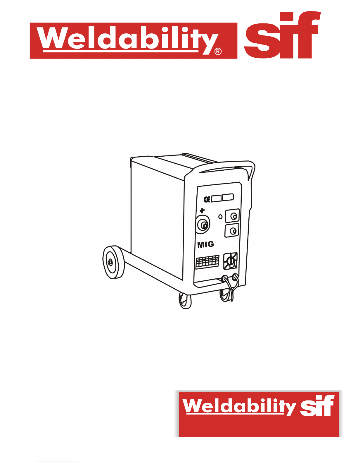
WELDABILITY MIG200E MACHINE
®
FAX : (+44) 01462 482202
Page 2
Page 1 of 13
INST R U C T I O N M AN U A L
WARNING: BEFORE USING THE MACHINE READ THE INSTRUCTION MANUAL CAREFULLY!
SECTION 1 : PRODUCT AND COMPANY IDENTIFICATION
PRODUCT NAME :
Weldability MIG200E Machine
SYNONYMS :
Continuous wire welding machine for MIG/MAG and flux arc welding, designed for
industrial and professional use.
PRODUCT CODES :
TWX1M200E
SUPPLIER :
Weldability | Sif
ADDRESS :
Peters House, The Orbital Centre, Icknield Way, Letchworth Garden City,
Hertfordshire. SG6 1ET. UK.
CONTACT PHONE :
+44 (0) 1462 482200
CONTACT FAX :
+44 (0) 1462 482202
PRODUCT USE :
MIG/MAG welding applications.
PREPARED BY :
Technical Support Team, Weldability | Sif
SECTION 2 : GENERAL SAFETY CONSIDERATIONS FOR ARC
WELDING
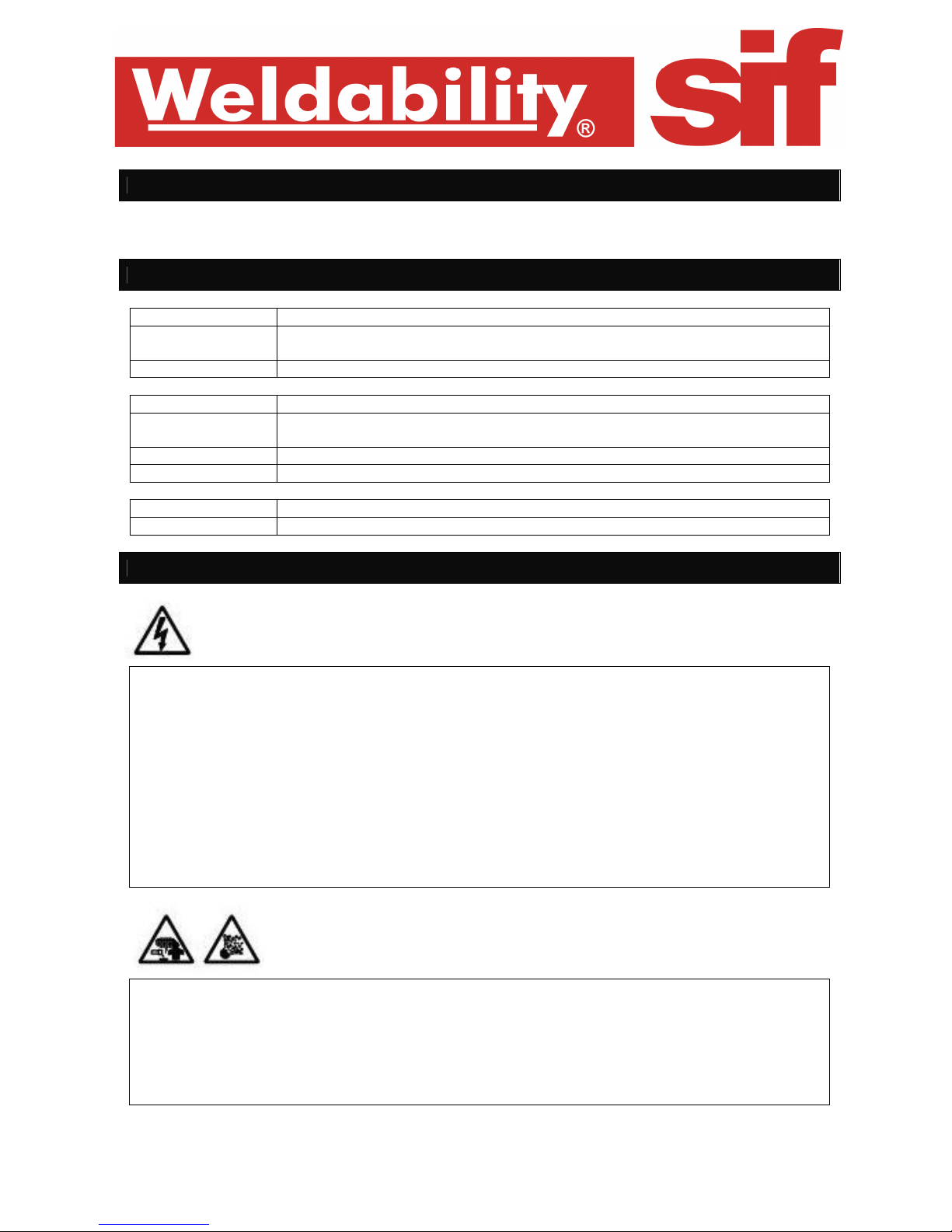
• Avoid direct contact with the welding circuit: the no-load voltage supplied by the welding machine
can be dangerous under certain circumstances.
• When the welding cables are being connected, or checks and repairs are carried out, the welding
machine should be switched off and disconnected from the power supply outlet.
• Switch off the welding machine and disconnect it from the power supply outlet before replacing
consumable torch parts.
• Make the electrical connections and installation according to the safety rules and legislation in
force.
• The welding machine should be connected only and exclusively to a power source with the neutral
lead connected to earth.
• Make sure that the power supply plug is correctly connected to the earth protection outlet.
• Do not use the welding machine in damp or wet places and do not weld in the rain.
• Do not use cables with worn insulation or loose connections.
• Keep the gas bottle (if used) away from heat sources, including direct sunlight.
• Do not weld on containers or piping that contains or has contained flammable liquid or gaseous
products.
• Do not operate on materials cleaned with chlorinated solvents or near such substances.
• Do not weld on containers under pressure.
• Remove all flammable materials (e.g. wood, paper, rags etc) from the working area.
• Provide adequate ventilation or facilities for the removal of welding fumes near the arc; a systematic
approach is needed in evaluating the exposure limits for the welding fumes, which will depend on
their composition, concentration and the length of exposure itself.
Page 3
Page 2 of 13
• Use adequate electrical insulation with regard to the electrode, the work piece and any (accessible)
earthed metal parts in the vicinity.
• This is normally achieved by wearing gloves, shoes, head coverings and clothing designed for this
purpose and by using insulating platforms or mats.
• Always protect your eyes using masks or helmets with special actinic glass.
• Use special fire-resistant protective clothing and do not allow the skin to be exposed to the
ultraviolet and infrared rays produced by the arc; other people in the vicinity of the arc should be
protected by shields of non-reflecting curtains.
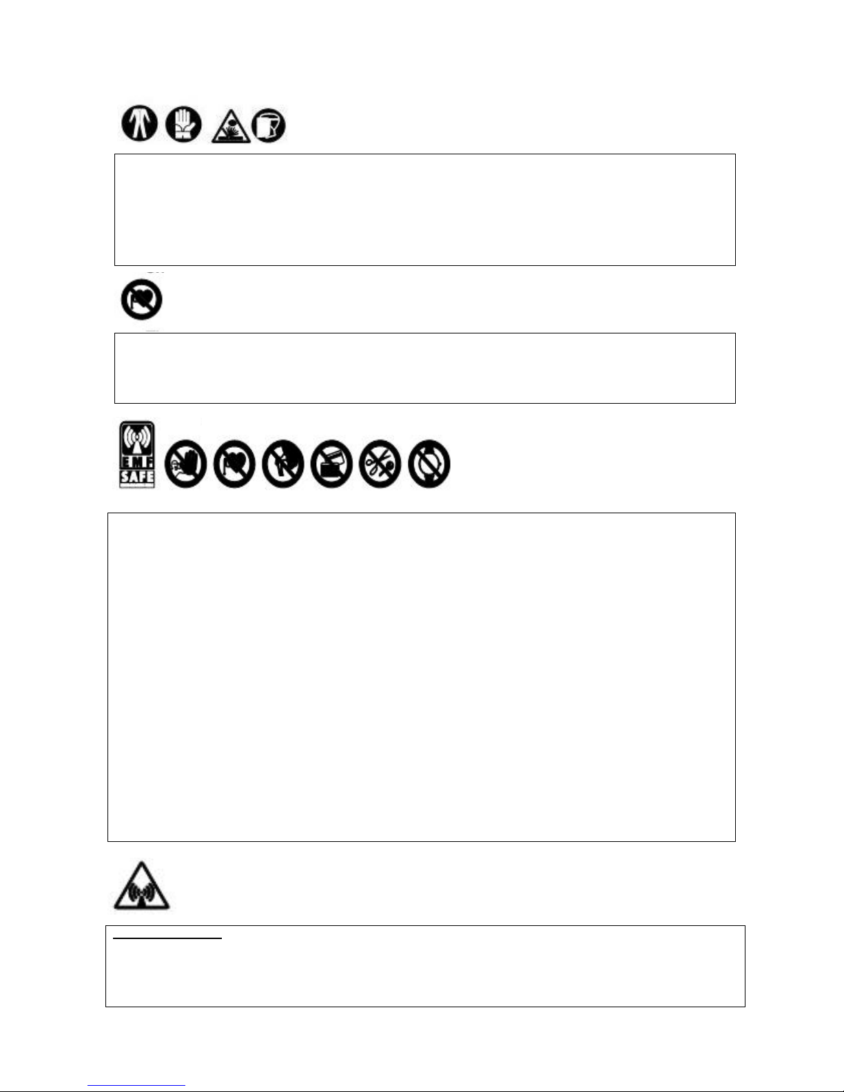
• The electromagnetic fields generated by the welding process may interfere with the operation of
electrical and electronic equipment.
• Users of vital electrical or electronic devices (e.g. pace-makers, respirators etc) should consult
a doctor before stopping in the vicinity of areas where this welding machine is used.
• Users of vital electrical or electronic devices should not use the welding machine.
The flow of the welding current generates electromagnetic fields (EMF) around the welding circuit.
Electromagnetic fields can interfere with certain medical equipment (e.g. Pace-makers, respiratory equipment,
metallic prostheses etc.). Adequate protective measures must be adopted for persons with these types of
medical apparatus. For example, they must be forbidden access to the area in which welding machines are in
operation.
This welding machine conforms to technical product standards for exclusive use in an industrial environment
for professional purposes. It does not assure compliance with the basic limits relative to human exposure to
electromagnetic fields in the domestic environment.
The operator must adopt the following procedures in order to reduce exposure to electromagnetic fields:
THE INSTRUCTION MANUAL CAREFULLY.
• Fasten the two welding cables as close together as possible.
• Keep head and trunk as far away as possible from the welding circuit.
• Never wind welding cables around the body.
• Avoid welding with the body within the welding circuit. Keep both cables on the same side of the
body.
• Connect the welding current return cable to the piece being welded, as close as possible to the
welding joint.
• Do not weld while close to, sitting on or leaning against the welding machine (keep at least 50 cm
away from it).
• Do not leave objects in ferromagnetic material in proximity of the welding circuit.
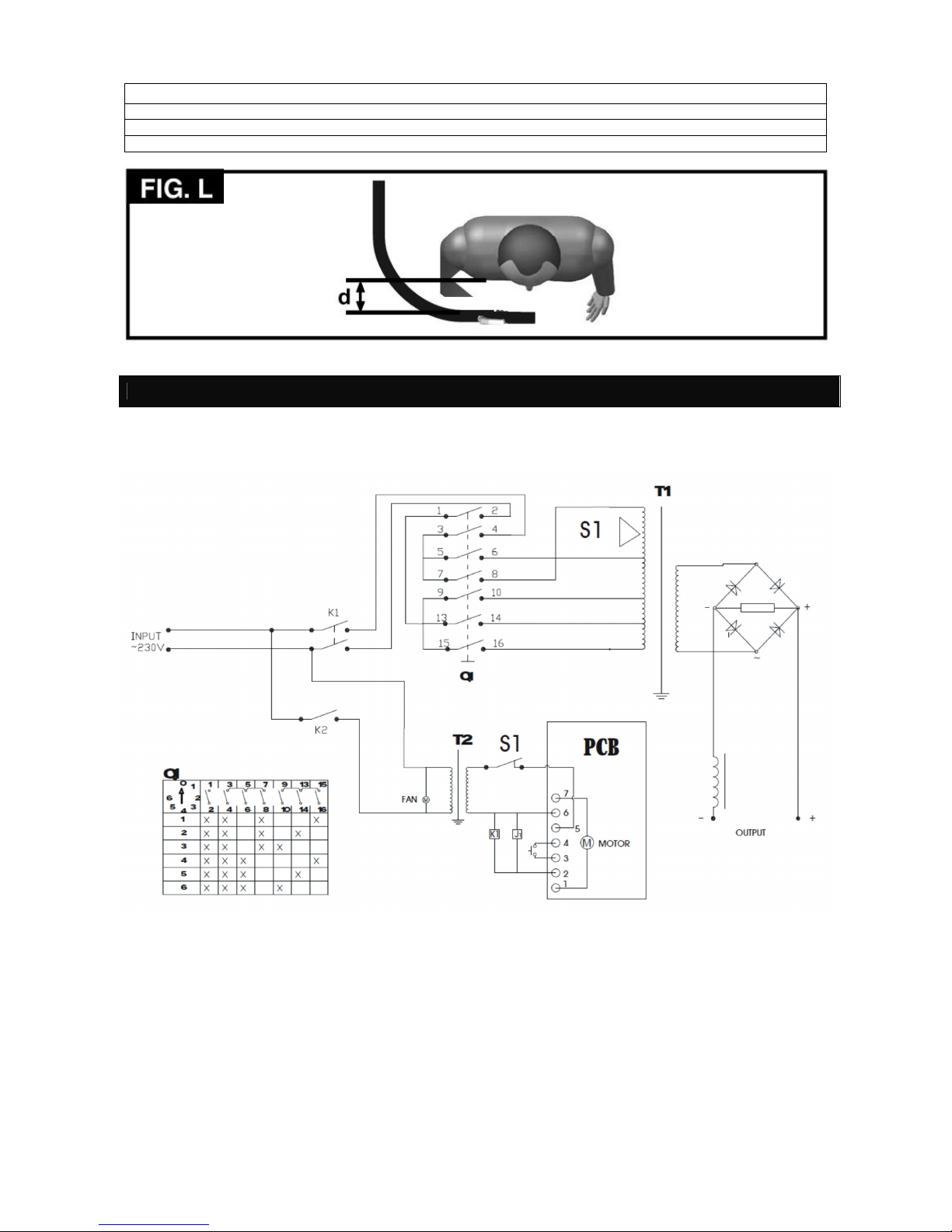
• Minimum distance d= 20 cm (Fig. L).
Class A equipment:
This welding machine conforms to technical product standards for exclusive use in an industrial environment
and for professional purposes. It does not assure compliance with electromagnetic compatibility in domestic
dwellings and in premises directly connected to a low-voltage power supply system feeding buildings for
domestic use.
Page 4
Page 3 of 13
SECTION 3 : EXTRA PRECAUTIONS
WELDING OPERATIONS:
• in environments with increased risk of electric shock;
• in confined spaces;
• in the presence of flammable or explosive materials;
MUST be evaluated in advance by an “expert supervisor” and must always be carried out in the presence of
other people trained to intervene in emergencies.
- Do not weld if the welding machine or wire feeder is supported by the operator (e.g. using belts).
- The operator must not weld in raised positions unless safety platforms are used.
VOLTAGE BETWEEN ELECTRODE HOLDERS OR TORCHES:
- Working with more than one welding machine on a single piece, or on pieces that are connected
electrically, may generate a dangerous accumulation of no-load voltage between two different electrode
holders or torches, the value of which may reach double the allowed limit.
- An expert coordinator must use measuring instruments to determine the existence of a risk and should
take suitable protection measures.
SECTION 4 : OTHER RISK WARNINGS
OVERTURNING:
Position the welding machine on a horizontal surface that is able to support
the weight to avoid the danger of overturning (e.g. inclined or uneven floors
etc).
IMPROPER USE:
It is hazardous to use the welding machine for any work other than that for
which it was designed (e.g. de-icing mains water pipes). Do not use the
handle to hang up the welding machine.
MOVING THE WELDING
MACHINE
Always secure the gas bottle, taking suitable precautions so prevent it falling
accidentally (if used).
• The safety guards and moving parts of the covering of the welding machine and of the wire feeder
should be in their proper positions before connecting the welding machine to the power supply.
WARNING! Any manual operation carried out on the moving parts of the wire feeder should be carried out
with the welding machine switched off and disconnected from the power supply outlet. These operations
may include:
• Replacing rollers and/or the wire guide;
• Inserting wire in the rollers;
• Loading the wire reel;
• Cleaning the rollers, the gears and the area underneath them;
• Lubricating the gears.
NEVER LIFT THE WELDING MACHINE - None of the welding machines described in this manual are equipped
with a lifting device.
Page 5
Page 4 of 13
SECTION 5 : INTRODUCTION AND GENERAL DESCRIPTION
This welding machine is a power source used for arc welding and has been designed specifically for MAG welding of
carbon steel and low-alloyed steel with either CO2 or an Argon/CO2 mixture shielding gas using solid or cored
(tubular) electrode wires.
The machine is also suitable for MIG welding of stainless steel using argon gas with 1-2% oxygen, and of aluminium
with argon gas, using electrode wires with a composition suited to the piece to be welded.
It is also possible to use cored wires in applications without protective gas by adapting the polarity of the torch to the
wire manufacturer’s recommendations.
Torch
Return cable and earth clamp
STANDARD ACCESSORIES:
Wheels kit (in models on wheels)
Page 6
Page 5 of 13
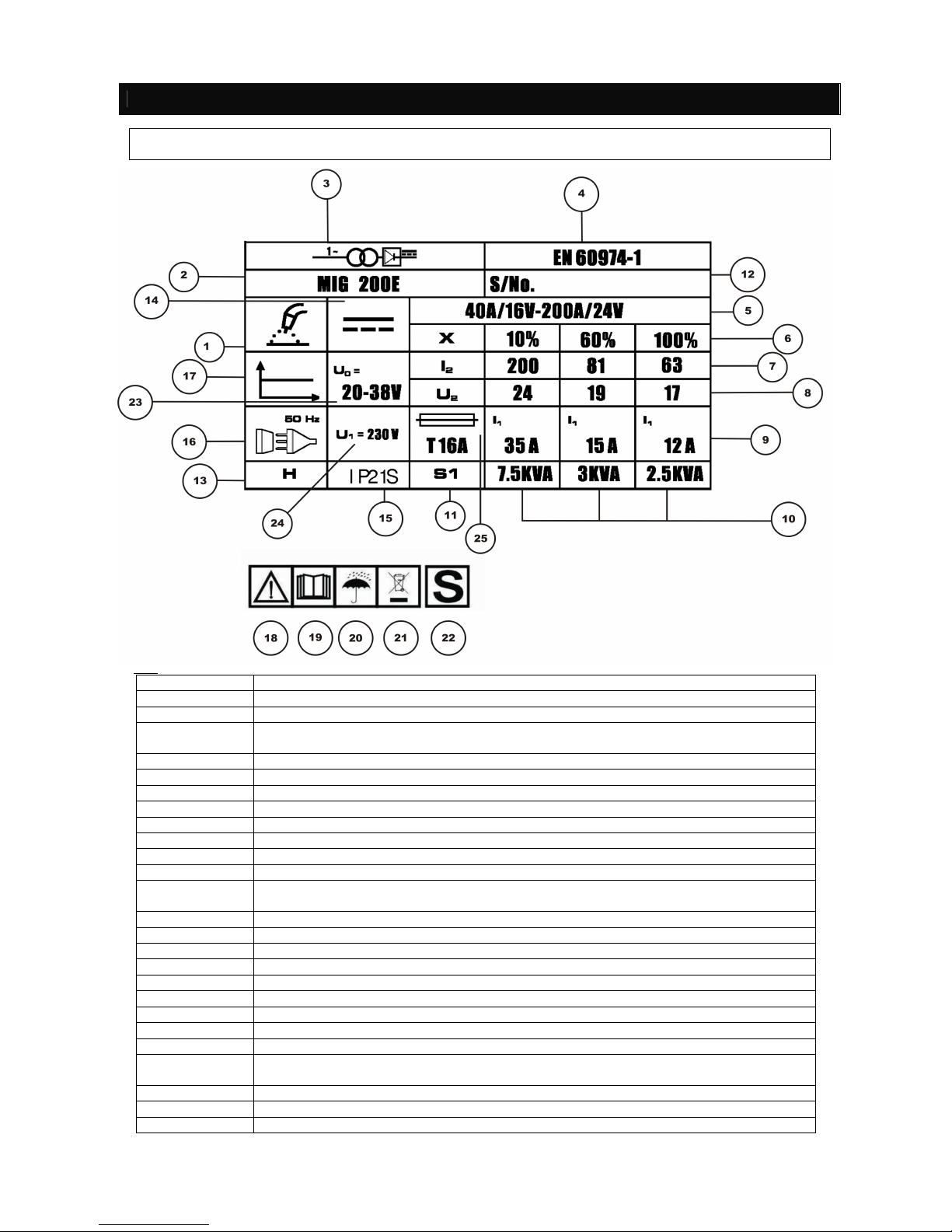
SECTION 6 : TECHNICAL DATA & PLATE DATA
The most important data regarding use and performance of the welding machine are summarised on the rating plate
and have the following meaning:
Key
Section Number Description
1
Symbol of the welding procedure chosen: metal inert gas
2
Machine
3
Symbol of the internal structure of the machine: frequency converter (inverter) – transformer rectifier
4
European norm regarding safety and the construction of arc welding machines
5
Output current range
6
Duty cycle
7
Output current
8
Output voltage
9
Input current / fuse draw
10
Input power requirements
11
Efficiency
12
Serial number. Identification of machine (necessary for technical assistance, requests for
parts and for tracing product origin).
13
Thermal class of insulation. H=180C
14
Mains input voltage
15
Case protection grade
16
Symbol of mains: alternative voltage – single phase
17
Symbol of the welding current characteristics = straight characteristic – constant voltage
18
Warning
19
Please read the instruction manual carefully
20
Do not use in wet conditions
21
Dispose correctly or recycle
22
Indicates that welding operations may be carried out in areas with greater risk of electric
shock (e.g. close to metal masses)
23
Open circuit volts
24
Primary input voltage supply
25
Fuse rating recommendation
Page 7
Page 6 of 13
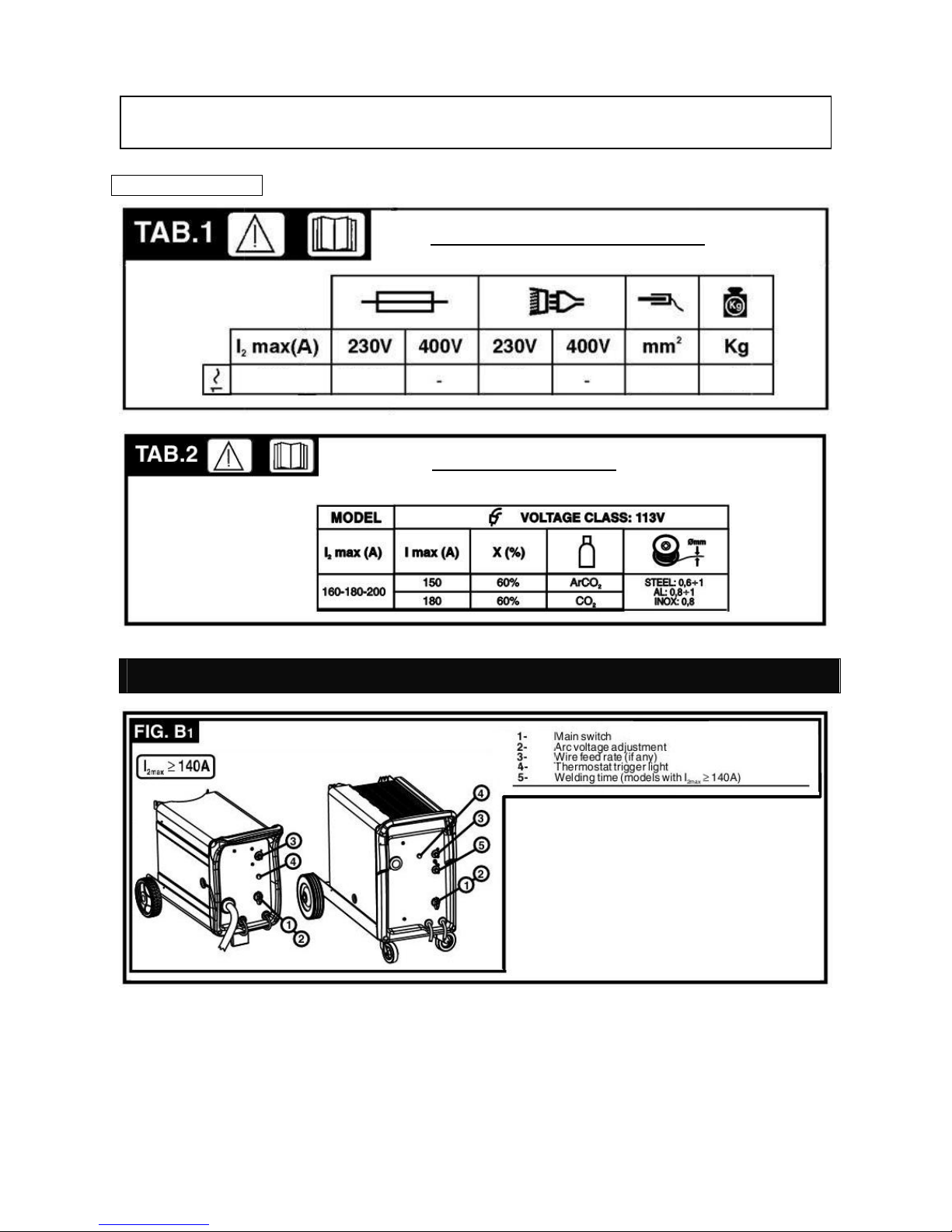
SECTION 7: DESCRIPTION OF THE WELDING MACHINE CONTROL, ADJUSTMENT AND
CONNECTION DEVICES
Other Technical Data
The data plate shown is an example to give the meaning of the symbols and numbers; the exact values of technical
data for the welding machine in your possession must be checked directly on the data plate of the wedling machine
itself.
WELDING MACHINE TECHNICAL DATA
TORCH TECHNICAL DATA
200 T25A
32A
16
51
Page 8
Page 7 of 13
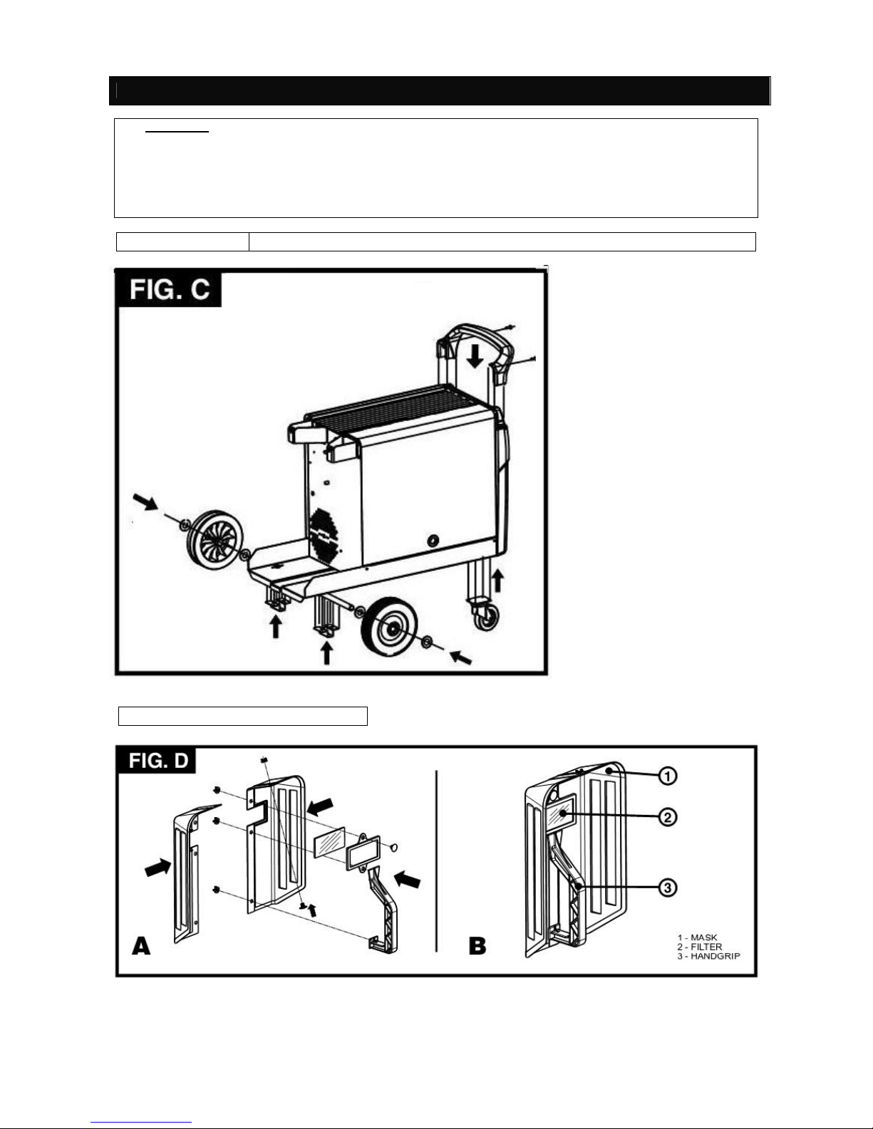
SECTION 8 : INSTALLATION
PREPARATION:
Unpack the welding machine; assemble the separate parts contained in the package.
ASSEMBLING THE PROTECTIVE MASK
WARNING!
• CARRY OUT ALL INSTALLATION OPERATIONS AND ELECTRICAL CONNECTIONS WITH THE
WELDING MACHINE COMPLETELY SWITCHED OFF AND DISCONNECTED FROM THE POWER
SUPPLY OUTLET.
• THE ELECTRICAL CONNECTIONS MUST BE MADE ONLY AND EXCLUSIVELY BY AUTHORISED OR
QUALIFIED PERSONNEL.
Page 9
Page 8 of 13
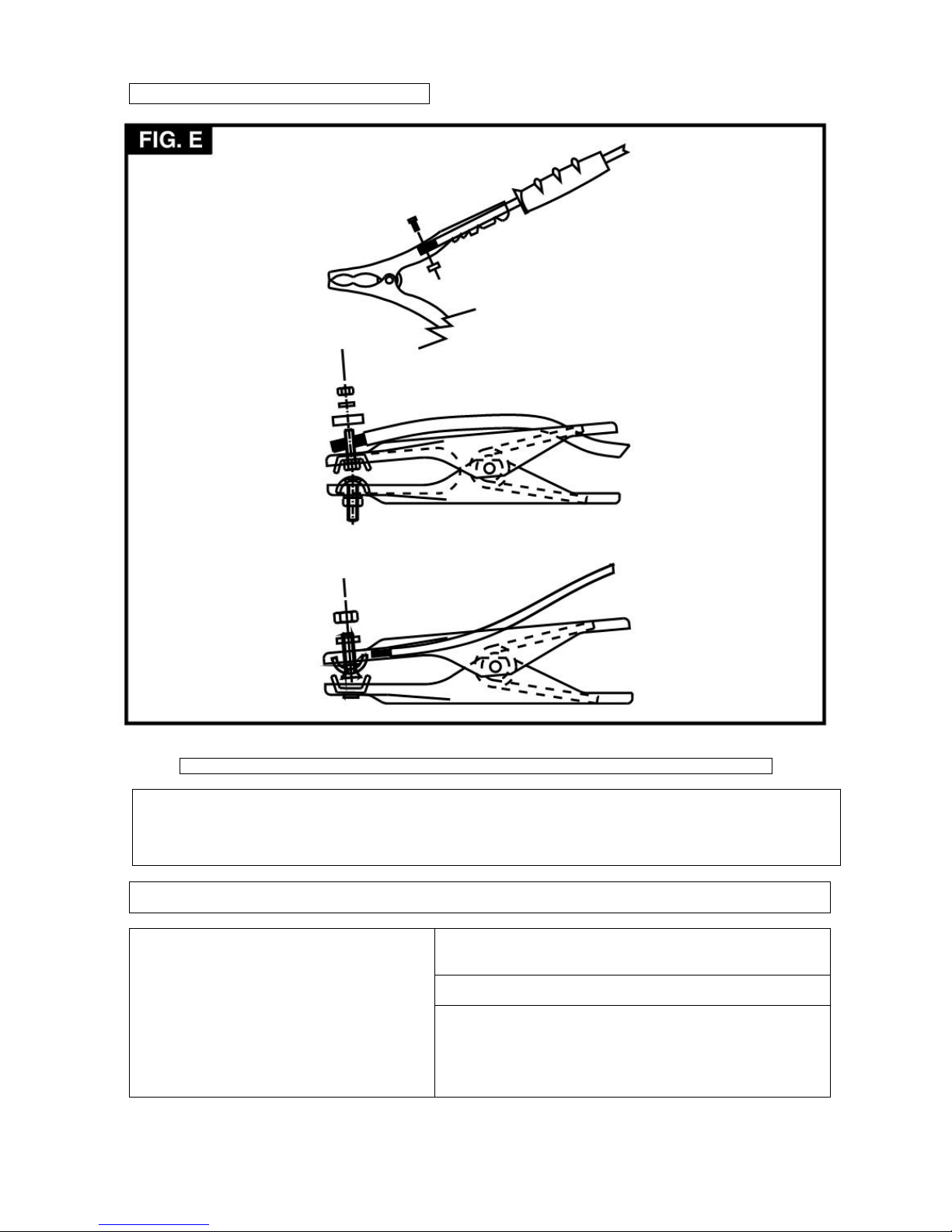
ASSEMBLING THE RETURN CABLE-CLAMP
SITE:
Locate the welding machine in an area where the opening for cooling air is not obstructed (forced circulation with fan).
Leave at least 250mm free space around the welding machine and check that conductive dusts, corrosive vapours or
humidity will not enter the welding machine.
WARNING! POSITION THE WELDING MACHINE ON A FLAT SURFACE WITH SUFFICIENT CARRYING
CAPACITY FOR ITS WEIGHT, TO PREVENT IT FROM TIPPING OR MOVING HAZARDOUSLY.
Before making any electrical connection, make sure the rating
data of the welding machine corresponds to the mains voltage
and frequency available at the place of installation.
The welding machine should only be connected to a power
supply system with the neutral conductor connected to earth.
CONNECTION TO THE MAIN POWER SUPPLY
To comply with the requirements of the EN 61000-3-
11 (Flicker)
Welding procedure standard we recommend connecting the
welding machine to interface points of the power supply that
have an impedance of less than Zmax =0,1 ohm. The welding
machine falls within the requisites of IEC/EN 61000-3-12
standard.
None of the welding machines described in this manual are equipped with a lifting device.
Page 10
Page 9 of 13
PLUG AND OUTLET.
(FOR WELDING MACHINES WITHOUT A
PLUG) :
Connect a normalised plug (2P + T) with sufficient capacity to
the power cable and prepare a mains outlet fitted with fuses or
an automatic circuit-breaker; the special earth terminal should
be connected to the earth conductor (yellow-green) of the power
supply. Remember that the angle of the electrode as it
advances should be line. Table 1 (TAB.1) shows the
recommended delayed fuse sizes in amps, chosen according to
the max nominal current supplied by the welding machine, and
the nominal voltage of the main power supply.
WARNING!
Failure to observe the above rules will make the (Class 1) safety system installed by the manufacturer
ineffective with consequent serious risks to persons (e.g. electric shock) and objects (e.g. fire).
CONNECTION OF THE WELDING CABLES
Table 1 (TAB. 1) gives the recommended values for the
welding cables depending on the maximum current supplied by
the welding machine.
WARNING! BEFORE MAKING CONNECTIONS MAKE SURE THE WELDING MACHINE IS SWITCHED OFF AND
DISCONNECTED FROM THE POWER SUPPLY OUTLET.
CONNECTION TO THE GAS BOTTLE (IF USED)
- A gas bottle can be loaded on the welding machine bottle
support platform: max 20kg.
- Screw the pressure reducing valve on to the gas bottle
valve, inserting the appropriate adapter for argon or an
argon/C02 mixture.
- Connect the gas inlet pipe to the pressure-reducing
valve(*) and tighten the band supplied.
- Loosen the adjustment ring nut on the pressure-reducing
valve before opening the bottle valve.
CONNECTING THE WELDING CURRENT
RETURN CABLE
- This is connected to the piece being welded or to the metal
bench supporting it, as close as possible to the join being
made.
CONNECTING THE TORCH (ONLY FOR
VERSIONS WITH EURO CONNECTOR)
- Engage the torch with its dedicated connector by
tightening the locking ring manually as far down as it will
go. Prepare the wire for loading by dismantling the
nozzles and the contact tube to ease its exit.
(*) Accesssory to be purchased seperately if not supplied with the product.
LOADING THE WIRE REEL
Page 11
Page 10 of 13
WARNING!
Before starting the operations to load the wire make sure the welding machine is switched off and
disconnected from the main power supply outlet.
ENSURE THAT THE WIRE FEEDER ROLLERS, THE WIRE GUIDE HOSE AND THE CONTACT TIP MATCH THE
DIAMETER AND TYPE OF WIRE TO BE USED AND MAKE SURE THAT THESE ARE FITTED CORRECTLY.
WHEN INSERTING AND THREADING THE WIRE, DO NOT WEAR PROTECTIVE GLOVES.
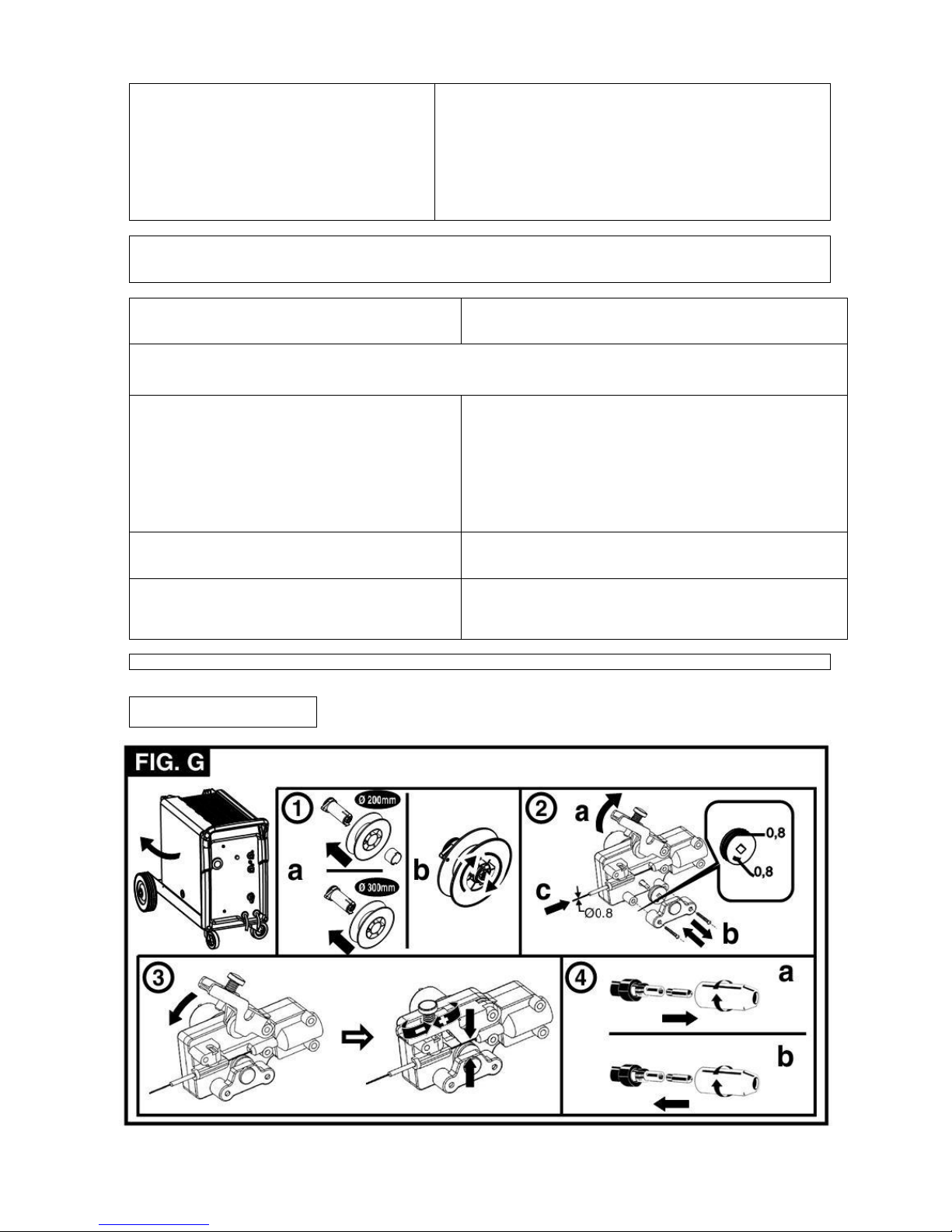
- Open the reel compartment door.
- Position the wire reel on the spindle. Holding the end of the wire upwards make sure the tab for pulling the spindle
is correctly seated in its hole (1a).
- Release the pressure counter-roller(s) and move away from the lower roller(s) (2a).
- Make sure that the towing roller(s) is suited to the wire used (2b).
- Free the end of the wire and remove the distorted end with a clean cut and no burr. Turn the reel anti-clockwise and
thread the end of the wire in to the wire-guide infeed, pushing it 50-100mm in to the wire guide of the torch fitting (2c).
- Re-position the counter-roller(s), adjusting the pressure to an intermediate value, and make sure that the wire is
correctly positioned in the groove of the lower roller (3).
- Use the adjustment screw located at the centre of the spindle to apply a slight braking pressure on the spindle itself
(1b).
- Remove the nozzles and contact tip (4a).
- Insert the welding machine plug in the power supply outlet, switch on the welding machine, press the torch button
and wait for the end of the wire to pass through the whole of the wire guide hose and protrude by 10-15cm from the
front part of the torch. Release the button.
WARNING!
DURING THESE OPERATIONS THE WIRE IS LIVE AND SUBJECT TO MECHANICAL STRESS.
ADEQUATE PRECAUTIONS MUST BE TAKEN TO PREVENT HAZARDOUS ELECTRIC SHOCK, INJURY
AND STRIKING OF ELECTRIC ARCS. THESE PRECAUTIONS ARE AS FOLLOWS:
• Do not direct the mouthpiece of the torch towards parts of the body.
• Keep the torch away from the gas bottle.
• Re-fit the contact tip and the nozzle on to the torch (4b).
• Check that wire feed is regular, set the roller and spindle braking pressure to the minimum possible
values making sure that the wire does not slide in the groove and when feed is halted the loops of
wire are not loosened by excessive reel inertia.
• Cut the end of the wire so that 10-15mm protrudes from the nozzle.
• Close the reel compartment door.
- Connect the return cable to the piece to be welded.
- Check the polarity (only for flux versions)
- If solid wire is used, open and adjust the flow of shielding gas by means of the pressure reducer.
NOTE: Remember to shut the shielding gas off when you finish work.
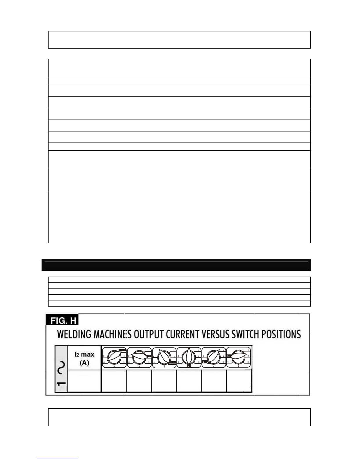
- Switch the welder on and set the welding current by means of the switches or rotary switch (if any).
- To start welding press the torch button.
NOTE: To adjust the welding parameters adjust the wire feed rate using the appropriate knob until even welding is
obtained (Fig.B-3).
SECTION 8 : WELDING: DESCRIPTION OF THE PROCEDURE
200T
40A
70A
89A
107A
133
A
172A
(max
200A)
Page 12
Page 11 of 13
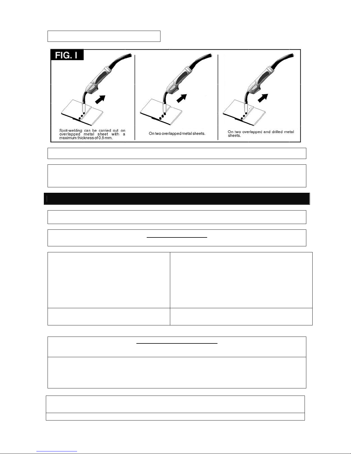
SPOT WELDING FUNCTION (where provided)
NOTE: To change the welding time operate the adjusting knob (Fig.B-5)
WARNING!
In some models the wire-guide tip is normally live; take care to prevent unwanted strikes.
The indicator light comes on when there is overheating and cuts off the power supply. It will reset
automatically within a few minutes after cooling down.
SECTION 9 : MAINTENANCE
WARNING! BEFORE CARRYING OUT MAINTENANCE OPERATIONS MAKE SURE THE WELDING MACHINE
IS SWITCHED OFF AND DISCONNECTED FROM THE MAIN POWER SUPPLY.
ROUTINE MAINTENANCE:
ROUTINE MAINTENANCE OPERATIONS CAN BE CARRIED OUT BY THE OPERATOR.
TORCH
- Do not put the torch or its cable on hot pieces; this would
cause the insulating materials to melt, making the torch
unusable after a very short time.
- Make regular checks on the gas pipe and connector seals.
- Every time the wire reel is changed, blow out the wireguide hose using dry compressed air (max. 5 bar) to make
sure it is not damaged.
- Before every use, check the wear and correct assembly of
the parts at the end of the torch: nozzle, contact tip, gas
diffuser.
WIRE FEEDER
- Make frequent checks on the state of wear of the wire
feeder rollers, regularly remove the metal dust deposited in
the feeder area (rollers and wire-guide infeed and outfeed.
EXTRAORDINARY MAINTENANCE:
EXTRAORDINARY MAINTENANCE OPERATIONS SHOULD BE CARRIED OUT ONLY AND EXCLUSIVELY BY
SKILLED OR AUTHORISED ELECTRICAL-MECHANICAL TECHNICIANS.
WARNING! BEFORE REMOVING THE WELDING MACHINE PANELS AND WORKING INSIDE THE MACHINE
MAKE SURE THE WELDING MACHINE IS SWITCHED OFF AND DISCONNECTED FROM THE MAIN POWER
SUPPLY OUTLET. IF CHECKS ARE MADE INSIDE THE WELDING MACHINE WHILE IT IS LIVE, THIS MAY
CAUSE SERIOUS ELECTRIC SHOCK DUE TO DIRECT CONTACT WITH LIVE PARTS AND/OR INJURY DUE TO
DIRECT CONTACT WITH MOVING PARTS.
- Inspect the welding machine regularly, with a frequency depending on use and the dustiness of the environment,
and remove the dust deposited on the transformer, reactance and rectifier using a jet of dry compressed air (max. 10
bar).
- Do not direct the jet of compressed air on the electric boards; these can be cleaned with a very soft brush or suitable
Page 13
Page 12 of 13
SECTION 10 : CIRCUIT DIAGRAM
solvents.
- At the same time make sure the electrical connections are tight and check the wiring for damage to the insulation.
- At the end of these operations, reassemble the panels of the welding machine and screw the fastenings right down.
- Never carry out welding operations while the welding machine is open.
Weldability MIG
200E
Page 14
Page 13 of 13
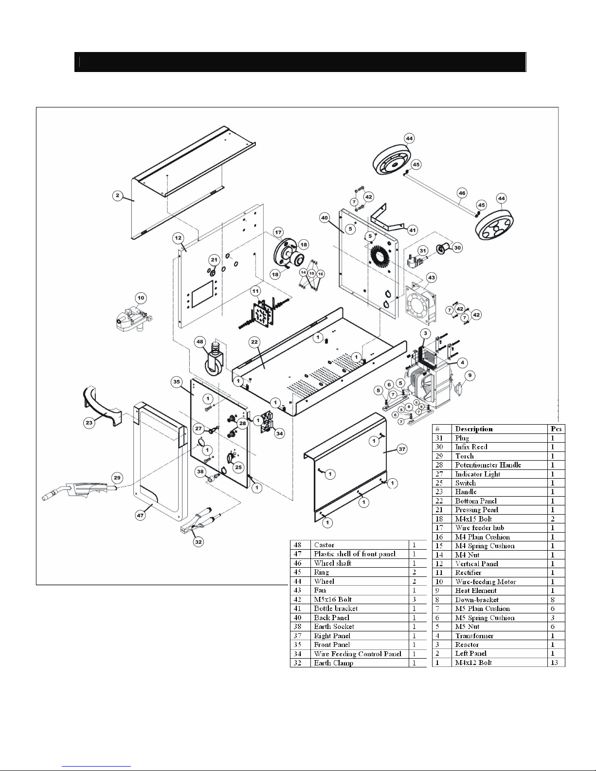
SECTION 11 : REPLACEMENT PARTS
For further information, contact Weldability | Sif technical support on 0870 330 7757 or email [email protected]
Doc Ref: SIF/MANUAL/MIG200E REV: 13.04.2011
Weldability MIG
200E
 Loading...