

Page 1
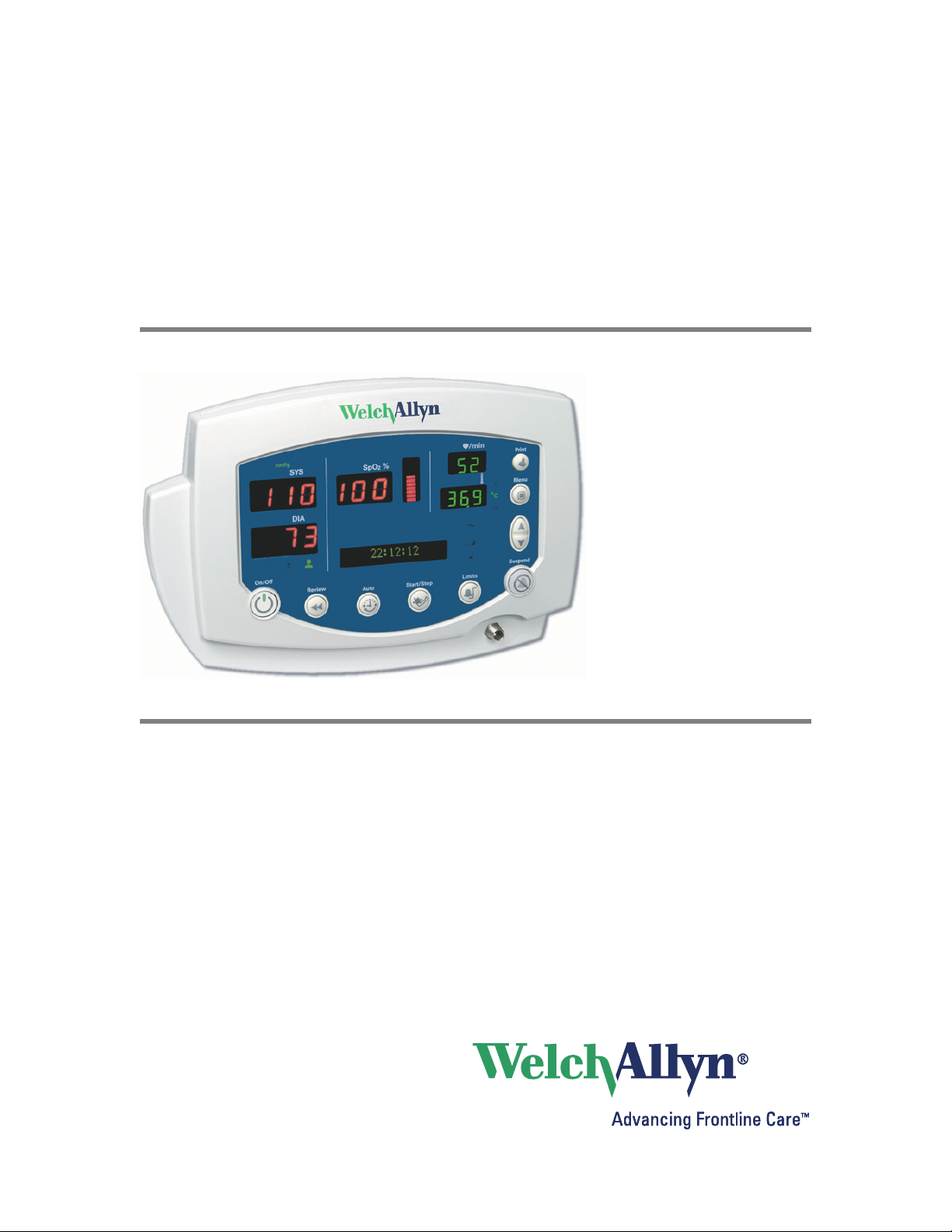
Vital Signs Monitor
300 Series
Service Manual
Page 2

ii Welch Allyn Vital Signs Monitor 300 Series
© 2011 Welch Allyn. All rights are reserved. To support the intended use of the product described in this publication, the
purchaser of the product is permitted to copy this publication, for internal distribution only, from the media provided by Welch
Allyn. No other use, reproduction, or distribution of this publication, or any part of it, is permitted without written permission
from Welch Allyn. Welch Allyn assumes no responsibility for any injury to anyone, or for any illegal or improper use of the
product, that may result from failure to use this product in accordance with the instructions, cautions, warnings, or statement
of intended use published in this manual.
Welch Allyn and Flexible Monitoring are registered trademarks of Welch Allyn. POEM and FlexNet are trademarks of Welch
Allyn.
Nellcor and Oximax are registered trademarks of Nellcor Puritan Bennett.
SET, LNCS, and Masimo are registered trademarks of Masimo Corporation. Possession or purchase of a Masimo SpO
-
2
equipped monitor does not convey any express or implied license to use the device with unauthorized sensors or cables
which would, alone or in combination with this device, fall within the scope of one or more of the patents relating to this
device.
Software in this product is copyright by Welch Allyn or its vendors. All rights are reserved. The software is protected by
United States of America copyright laws and international treaty provisions applicable worldwide. Under such laws, the
licensee is entitled to use the copy of the software incorporated with this instrument as intended in the operation of the
product in which it is embedded. The software may not be copied, decompiled, reverse-engineered, disassembled or
otherwise reduced to human-perceivable form. This is not a sale of the software or any copy of the software; all right, title
and ownership of the software remain with Welch Allyn or its vendors.
For information about any Welch Allyn product, call Welch Allyn Technical Support:
USA + 1 315 685 4560
Australia + 61 2 9638 3000
800 535 6663
Canada 800 561 8797 China + 86 216 327 9631
European Call Center + 35 3 46 906 7790 France + 33 1 55 69 58 49
Germany + 49 7477 92 71 86 Japan +81 42 703 6084
Latin America + 1 305 669 9003 Netherlands + 31 202 061 360
Singapore + 65 6419 8100 South Africa + 27 11 777 7555
United Kingdom + 44 20 7365 6780 Sweden + 46 8 58 53 65 51
This device complies with Part 15 of the FCC rules and with the rules of the Canadian ICES-003. Operation is subject to the
following two conditions: (1) This device may not cause harmful interference and (2) this device must accept any interference
received, including interference that may cause undesired operation.
Caution! Changes or modifications not expressly approved by Welch Allyn could void the purchaser’s authority to operate
the equipment.
810-2811-02 (CD)
Manual Part Number 810-1651-04 Rev A, 09/2011
Welch Allyn, Inc.
8500 SW Creekside Plac
Beaverton, OR 97008-7107 USA
Regulatory Affairs Representative
Welch Allyn Limited
Navan Business Park
Dublin Road, Navan
County Meath, Republic of Ireland
www.welchallyn.com
Printed in USA
Page 3

Service Manual iii
Safety.........................................................1
General safety considerations .............................................1
Electrostatic discharge (ESD) ..............................................2
Symbols ..............................................................3
Service overview.................................................5
Purpose and scope ......................................................5
Technical support services ................................................5
Returning products ......................................................6
Product configurations ...................................................6
Recommended service intervals ...........................................7
Service options .........................................................7
Related documents .....................................................7
Service menu ..........................................................7
Functional verification .............................................9
Functional verification overview ............................................9
Equipment required .....................................................9
Functional verification procedure ..........................................11
Checklist and test results report form ......................................31
Troubleshooting and repair ........................................33
Troubleshooting chart...................................................33
Requirements for module-level repair and replacement.........................36
NIBP characterization ...................................................36
Welch Allyn monitor service utility .........................................37
Disassembly procedure ..........................................55
Procedures overview ...................................................55
Remove and disconnect the battery........................................58
Separate the front and rear chassis ........................................59
Disassemble the front chassis assembly ....................................60
Remove the LCD display from the main board ...............................62
Disassemble the rear chassis assembly.....................................63
Remove the main board .................................................64
Disassemble and remove the NIBP assembly ................................67
Remove and replace the speaker ..........................................69
Remove and disassemble the printer assembly...............................71
Disassemble the temperature module ......................................79
Disassemble the Nellcor SpO2assembly....................................82
Disassemble the Masimo SpO2assembly ...................................85
Replacement parts ..............................................87
Updates and service bulletins......................................99
DC power cable clamp ..................................................99
Page 4

iv Welch Allyn Vital Signs Monitor 300 Series
Page 5
1
1
Safety
All personnel must read and understand all safety information presented in this manual
before using or repairing the monitor.
Caution Use only the Welch Allyn Monitor Service Utility (810-1784-XX) with
this monitor.
Software service tools, such as the “Custom Repair Software” (part number
130S29E), distributed for use with previous models of the Vital Signs Monitor,
must not be used with the Model 300 Series. Use of any tool other than the
Welch Allyn Monitor Service Utility (810-1784-XX) may set the monitor in an
undefined and unrecoverable state.
United States federal law restricts this device to sale, distribution, or use by or on the
order of a licensed medical practitioner.
General safety considerations
Always consider the following safety points when using the monitor:
• Place the monitor and accessories in locations where they cannot harm the patient
should they fall from a shelf or mount.
• Do not connect more than one patient to a monitor.
• Do not connect more than one monitor to a patient.
• Do not use the monitor in an MRI suite or hyperbaric chamber.
• Do not autoclave the monitor.
• Accessories can be autoclaved only if the manufacturer’s instructions clearly approve
it. Many accessories can be severely damaged by autoclaving.
• Inspect the power adapter cord periodically for fraying or other damage. Replace the
adapter as needed. Do not operate the monitor from mains power if the adapter, the
adapter cord, or the cord plug is damaged.
• Frequently check all cables, both electrically and visually.
• To avoid explosion, do not operate the monitor in the presence of flammable
anesthetics.
WARNING Use only accessories approved by Welch Allyn. Visit
www.welchallyn.com. The use of any other accessories can result in inaccurate
patient data, can damage the equipment, and can void your product warranty.
WARNING Always use accessories according to the standards of your facility
and according to the manufacturer's directions for use.
Page 6
2 Safety Welch Allyn Vital Signs Monitor 300 Series
• A monitor that has been dropped or otherwise damaged or abused must not be used
until it has been tested and verified by qualified service personnel for proper
operation.
• If the monitor detects an unrecoverable problem, an error code and a brief message
appear in the message display. Report all such errors to Welch Allyn.
• While under warranty, the monitor must be serviced only by a Welch Allyn service
technician.
Electrostatic discharge (ESD)
CAUTION
SENSITIVE ELECTRONIC DEVICES
DO NOT SHIP OR STORE NEAR STRONG
ELECTROSTATIC, ELECTROMAGNETIC,
MAGNETIC OR RADIOACTIVE FIELDS.
ATTENTION
OBSERVE PRECAUTIONS
FOR HANDLING
ELECTROSTATIC
SENSITIVE DEVICES
WARNING Electrostatic discharge (ESD) can damage or destroy electronic
components. Handle static-sensitive components only at static-safe workstation.
WARNING Consider all electrical and electronic components of the monitor as
static-sensitive.
Electrostatic discharge is a sudden current flowing from a charged object to another
object or to ground. Electrostatic charges can accumulate on common items such as
foam drinking cups, cellophane tape, synthetic clothing, untreated foam packaging
material, untreated plastic bags, and work folders, to name only a few.
Electronic components and assemblies, if not properly protected against ESD, can be
permanently damaged or destroyed when near or in contact with electrostatically charged
objects. When you handle components or assemblies that are not in protective bags and
you are not sure whether they are static-sensitive, assume that they are static-sensitive
and handle them accordingly.
• Perform all service procedures in a static-protected environment. Always use
techniques and equipment designed to protect personnel and equipment from
electrostatic discharge.
• Remove static-sensitive components and assemblies from their static-shielding bags
only at static-safe workstations—a properly grounded table and grounded floor mat—
and only when you are wearing a grounded wrist strap (with a resistor of at least 1
megohm in series) or other grounding device.
• Use only grounded tools when inserting, adjusting, or removing static-sensitive
components and assemblies.
• Remove or insert static-sensitive components and assemblies only with monitor
power turned off.
• Insert and seal static-sensitive components and assemblies into their original staticshielding bags before removing them from static-protected areas.
• Always test your ground strap, bench mat, conductive work surface, and ground cord
before removing components and assemblies from their protective bags and before
beginning any disassembly or assembly procedures.
Page 7
Service manual Safety 3
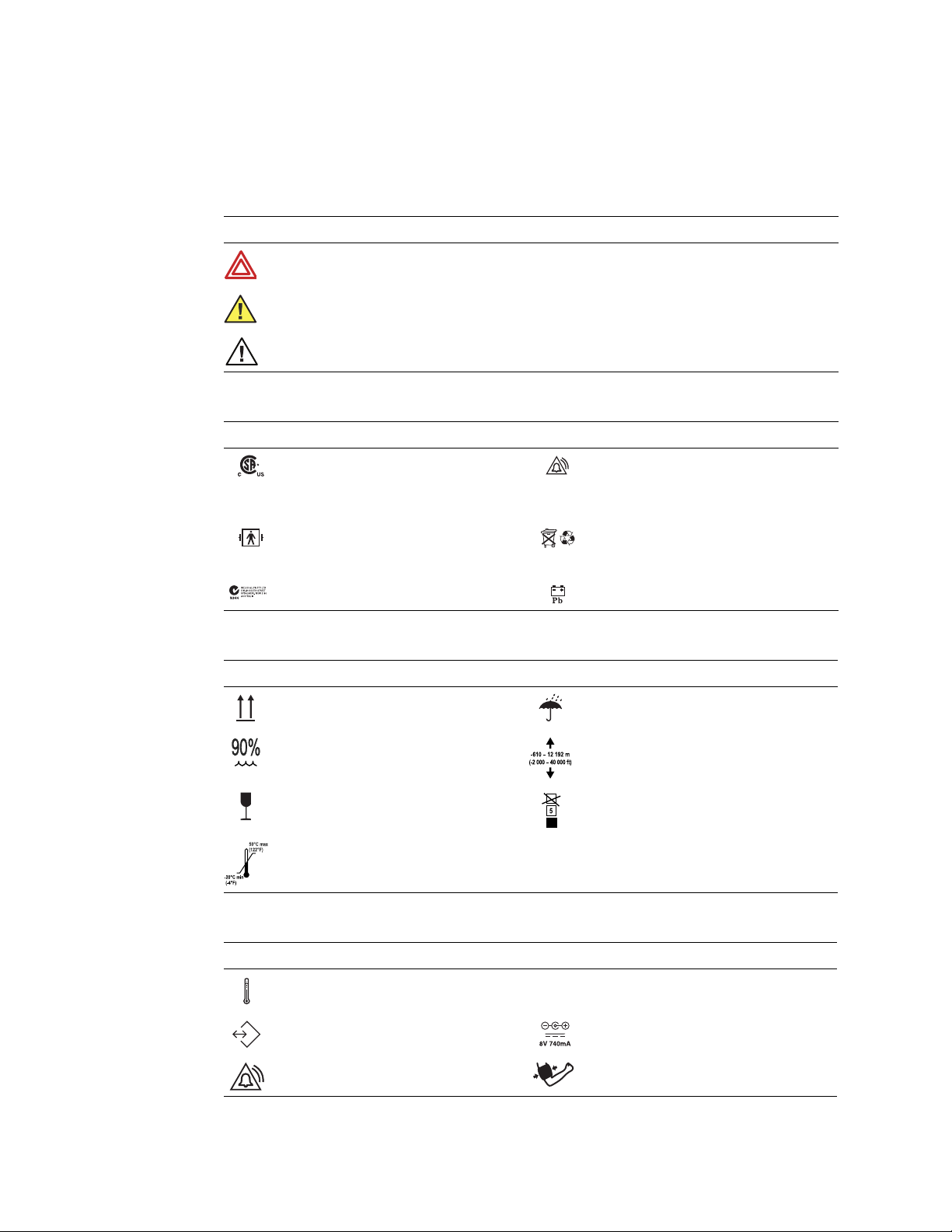
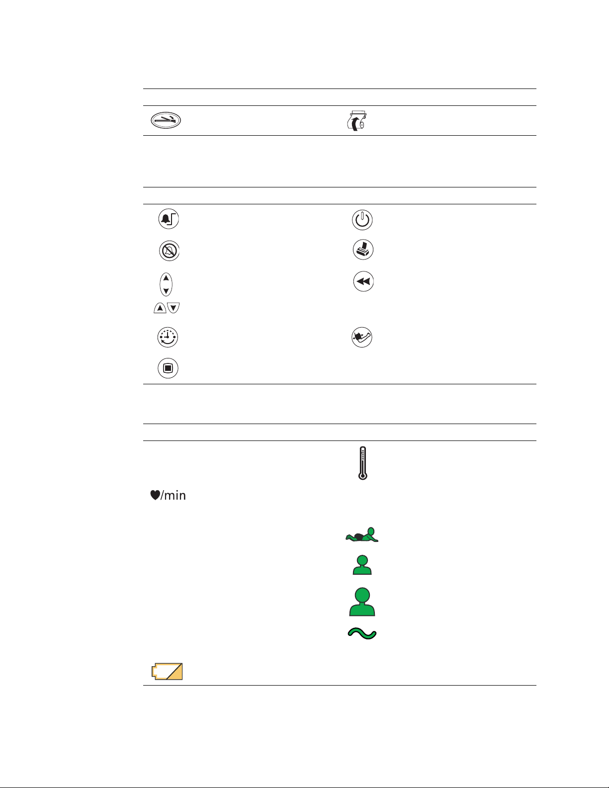
Symbols
The symbols illustrated on the following pages appear on the monitor or in this document.
Documentation symbols
WARNING Indicates conditions that could lead to illness, injury, or death.
Caution In this manual, indicates conditions that could damage equipment or other property.
Caution On the product, means “Consult accompanying documentation.”
Certification and operation labels
This device has been tested and certified by the
Canadian Standards Association International to
comply withapplicable U.S. and Canadian medical
safety standards.
Patient connections are Type BF, and protected
against defibrillation.
Australian Registered Importer Sealed lead-acid battery, 6V 4 Ah
Shipping, storing, and environment labels
Keep this end of the package or shipping crate up. Protect the monitor from exposure to rain.
Do not expose the monitor to relative humidity
above this limit.
Fragile contents—handle with care. Limit stacking to this number of units.
Do not expose the monitor to temperatures
outside these limits.
Urgent alarm notification (output to Nurse Call
system)
Recycle used batteries properly and in accordance
with local regulations.
Do not dispose of batteries in refuse containers.
Do not subject the monitor to altitudes outside
these limits.
Monitor connector labels
Temperature Probe Cable Connector SpO
RS232 Cable Connector AC Power Adapter Cable Connector
Nurse Call Cable Connector NIBP Hose Connector
SpO2Sensor Cable Connector
2
Page 8
4 Safety Welch Allyn Vital Signs Monitor 300 Series
ºC
ºF
M
Printer door label
Press to open the printer door Load paper this direction
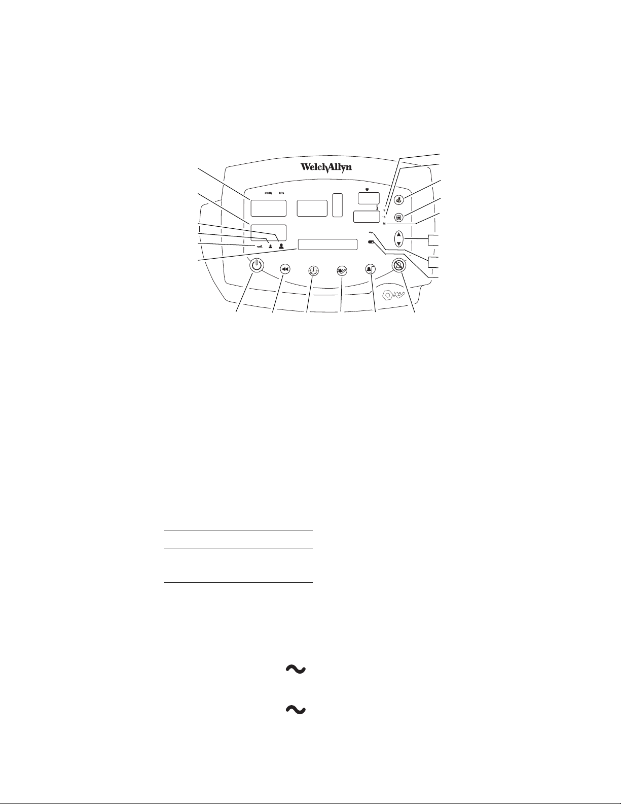
The monitor front panel controls are described in more detail throughout this document.
Front panel controls
Set alarm limits Power on/off
Silence alarms Print patient data
SYS
DIA
SpO
2
message
window
ºC
Scroll up/down, Scroll forward/back,
Increase/decrease value
(The scroll icon appears as these two
arrows in the documentation.)
Set an NIBP automatic measurement
interval
Cycle to the next menu selections
Front panel displays and indicators
Systolic pressure
Diastolic pressure
Arterial hemoglobin oxygen saturation
Pulse rate pulse
amplitude
indicator
MAP (mean arterial pressure) Neonatal
Degrees Celsius Pediatric
Review patient data
Start/stop an NIBP cycle (AUTO button)
Temperature
Pulse strength
ºF
M
Degrees Fahrenheit Adult
Monitored temperature AC power
Battery charging (flashing)
Battery charged (steady)
Battery low
Battery fully discharged
Page 9

5
2
Service overview
Purpose and scope
This service manual is a reference for periodic preventive maintenance and corrective
service procedures for the Vital Signs Monitor 300 Series.
Corrective service is supported to the level of field-replaceable units. These include some
circuit-board assemblies and some subassemblies, case parts, and other parts. (See
“Replacement parts” on page 87 for a complete list of user-replaceable service parts.)
Note
Repair and replacement of the main board is not supported. All service work on
the main board must be performed by certified and qualified service personnel at
an authorized Welch Allyn service center.
Caution No component-level repair of circuit boards and subassemblies is
supported. Use only the repair procedures described in this manual.
WARNING When performing a service procedure, follow the instructions
exactly as presented in this manual. Failure to do so could damage the monitor,
invalidate the product warranty, and lead to serious personal injury.
This guide provides troubleshooting information, assembly procedures, and instructions
for functional testing and performance verification. It is intended for use only by
technically qualified service personnel.
This guide applies only to the Vital Signs Model 300 Series. For servicing the previous
(52000-series) version of the Vital Signs Monitor, refer to Welch Allyn service manual
95P445E, which is available on the TechView CD (900298-1).
Technical support services
Welch Allyn offers the following technical support services:
Telephone support
Loaner equipment
Service agreements
Service training
Replacement service parts
Factory Service
For information on any of these services, contact Welch Allyn at the Technical Support:
numbers listed on page ii.
Page 10

6 Service overview Welch Allyn VSM 300 Series
Returning products
To return a product for service, contact Welch Allyn Technical Support and request a
Return Material Authorization (RMA) number.
Note
Welch Allyn does not accept returned products without an RMA.
When requesting an RMA, please have the following information available:
• Product name, model number, and serial number
• A complete return shipping address, including a contact name and phone
number; include any special shipping instructions
• A purchase-order number or credit-card number if the product is not covered by
warranty or service agreement
• A full description of the problem or service request
To ship the monitor, please observe these packing guidelines:
• Remove from the package all hoses, connectors, cables, sensors, power cords,
and other ancillary products and equipment, except those items that might be
associated with the problem.
• Use the original shipping carton and packing materials, or as close an
approximation as possible.
• Include a packing list.
• Write the Welch Allyn RMA number with the Welch Allyn address on the outside
of the shipping carton.
United States federal regulations require that any unit received by Factory Service must
be free from blood-borne pathogens before processing. All incoming products are cleaned
as well as possible, but products that cannot be effectively cleaned cannot be accepted
for repair. Please thoroughly clean all organic residues from the product before shipment.
This will ensure safe receipt, processing and repair, and will help expedite the return of
your monitor.
Product configurations
Model numbers for the configurations are as follows:
Model Features Model Features
53000 Standard (NIBP, Pulse Rate, and MAP) 530T0 Standard + Temperature
5300P Standard + Printer 530TP Standard + Temperature + Printer
®
53N00 Standard + Nellcor
53NT0 Standard + Nellcor SpO2+ Temperature 53ST0 Standard + Masimo SpO2+ Temperature
53N0P Standard + Nellcor SpO
53NTP Standard + Nellcor SpO
SpO
2
+ Printer 53S0P Standard + Masimo SpO2+ Printer
2
+ Temperature + Printer 53STP Standard + Masimo SpO2+ Temperature + Printer
2
53S00 Standard + Masimo®SpO
2
Page 11

Service manual Service overview 7
Recommended service intervals
Interval or Condition Action Recommended Procedure Page
Every6-24months
(per hospital protocols)
Battery does not hold a charge Check battery capacity
Monitor has been dropped or
otherwise damaged
Monitor malfunctioning Complete functional test Functional verification 9
Monitor does not pass
Functional Verification
Service options
Warranty service
All repairs on products under warranty must be performed or approved by Welch Allyn.
Refer all warranty service to Welch Allyn Factory Service or another authorized Welch
Allyn Service Center. Obtain an RMA number for all returns to Welch Allyn Factory
Service – see “Returning products” on page 6.
Caution Unauthorized repairs will void the product warranty.
Complete functional test Functional verification 9
Replace battery
Complete functional test Functional verification 9
Troubleshooting and repair followed by
functional test; if necessary, return to
authorized service center
Functional verification
Disassembly procedure
Troubleshooting and repair
Disassembly procedure
Functional verification
9
55
33
55
9
Non-warranty service
Welch Allyn Factory Service and authorized Service Centers support non-warranty repairs.
Contact any Welch Allyn regional service center for pricing and service options.
Welch Allyn offers modular repair parts for sale to support non-warranty service. This
service must be performed only by qualified end-user biomedical/clinical engineers using
this service manual.
The Welch Allyn Monitor Service Utility supports certain service functions. For
information, see “Welch Allyn monitor service utility” on page 37.
Related documents
Title Reorder number
Vital Signs Monitor 300 Series Directions for Use (Masimo, multilanguage) 810-2250-XX
Vital Signs Monitor 300 Series Directions for Use (Nellcor, multilanguage) 810-2252-XX
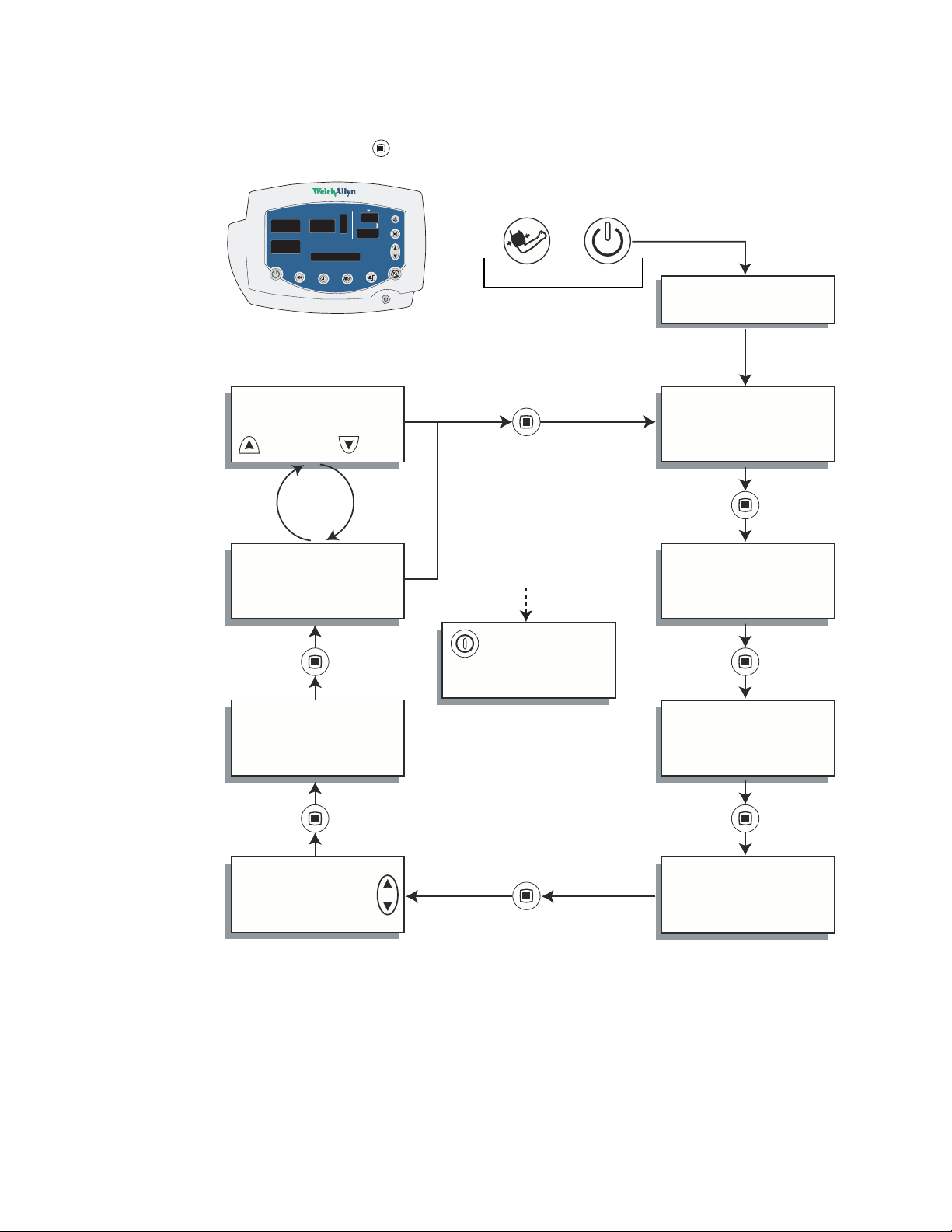
Service menu
To see the service menu, first power the monitor off. Press and hold for 3 seconds.
While is depressed, press until the monitor displays the message Service Mode.
Page 12
8 Service overview Welch Allyn VSM 300 Series
The monitor runs a self-test and then displays the main software version number
(M: X.XX.XX). Press repeatedly to cycle to the menu selection of interest.
SYS
DIA (mmHg)
/min
SpO2 %
3 seconds
SERVICE MODE
Power-up Self-test
RESET TO DEFAULT
Main SW version
M: X.XX.XX
YES
BP CYCLES:XXXXXX
RUN TIME:XXXXX
NO
NIBP SW version
N:XX.XX.XX
POWER OFF
BATTERY:X.XX V
NIBP TEST
Exit Service Mode
SpO
SW version
2
S:X.X.X.X
Temperature SW version
T:X.X
Page 13

9
3
Functional verification
Functional verification overview
This section describes the procedure for a complete functional test to support
recommended preventive-maintenance schedules.
The verification includes tests for a monitor configured with the printer, temperature, and
SpO2options. Perform only the tests applicable to the actual configuration.
A checklist of the functional tests is provided on “Checklist and test results report form”
on page 31. It is recommended that you print a copy of the checklist each time you
perform the functional verification procedure, so that you can record and save the test
results. If the monitor ever requires service, the records of test results can often facilitate
troubleshooting.
Functional verification does not require opening the monitor case.
Equipment required
This equipment is required for functional verification of a fully configured monitor.
Commercially available general-purpose/medical test equipment
Item Manufacturer part number/specification
Power supply Variable, 0-8 VDC, 0.75 amperes (minimum), with voltage and current
Digital pressure meter Netech Digimano 1000 or equivalent
AC withstand voltage (hi-pot) tester Associated Research 3605 or equivalent
functional tester (Nellcor, for testing
SpO
2
the monitor only)
SpO2functional tester (Masimo, for testing
the monitor only)
SpO2extension cable (required for SRCMAX)
SpO2simulator (for testing the monitor and
the SpO
Syringe, 60 mL, Slip tip, Luer BD (Becton, Dickinson) 309654 or equivalent
Hi-pot cable connectors See “Test connections” on page 29.
Timer (to display elapsed time, in seconds)
sensor)
2
indicators (for 1mA current measurement)
Nellcor SRC-MAX
Masimo Tester REF 1593
Nellcor DEC-8
Fluke (Biotek) Index2 XL/XLFE or equivalent
Page 14

10 Functional verification Welch Allyn VSM 300 Series
Welch Allyn accessories and test equipment
Order number Description
06138-000 Temperature test key
(for testing the monitor only)
01802-110, 110 V
01802-220, 220 V
9600 Plus Calibration Tester
(for testing the monitor and the temperature probe)
008-0265-XX Neonatal cuff hose, 96-inch
008-0620-XX Neonatal #1 cuff, disposable, box of 10
020-0702-XX Cuff simulator (or equivalent 500 cc test volume)
5200-101A DC power adapter
407590 Battery substitution connector
810-1784-XX Welch Allyn Monitor Service Utility
(required for NIBP repair or replacement;
not required for functional testing)
008-0842-XX Service Serial Cable (for use with the Welch Allyn Monitor
Service Utility 810-1784-XX)
WA 5088-01 Tycos air release valve and small bulb
600-0021-XX NIBP tubing connector, threaded
600-0179-XX Tubing, 1’
600-0043-XX Tee, plastic
Page 15
Service manual Functional verification 11
Fah
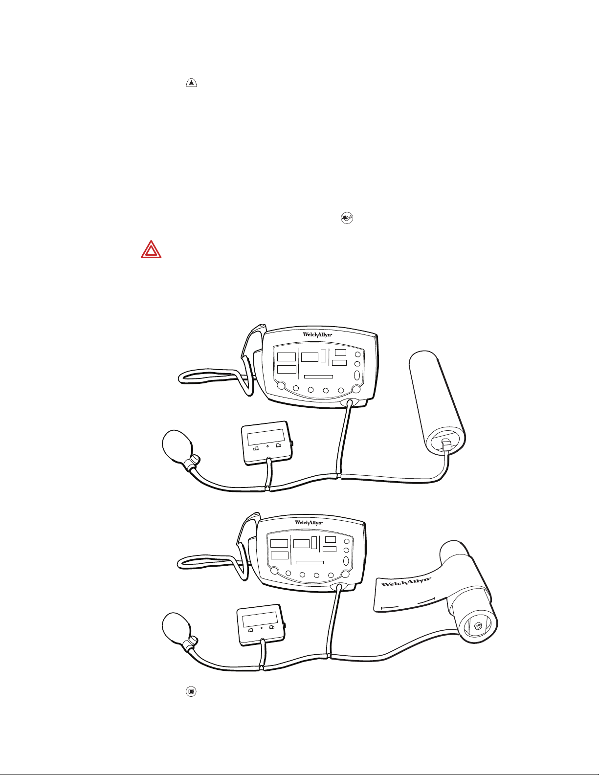
Functional verification procedure
Reference illustration
renheit
Systolic
window
Diastolic
window
Adult
Pediatric
Neonatal
Message
window
SYS
DIA
SpO2 %
/min
Celsius
Print patient data
Change settings
Monitored
temperature
Increase/Decrease
Forward/Back
Battery charged
Battery charging
Battery low
System/power
Note
Setup
• If the monitor is configured with the temperature option, connect the temperature
• If you are using an optional Welch Allyn Model Calibration Tester, plug it in and set it to
• If the monitor is configured with the SpO2option, connect the SpO2sensor.
Power
On/Off
Review
patient
data
Set
NIBP
interval
Start/
stop
NIBP
Set
alarm
limits
Silence
alarms
Other than the optional NIBP overpressure test (page 18), the tests described
here must be performed as part of a complete functional verification procedure.
probe and insert it into the probe well.
the values that match your tester model:
Model Temperature
9600 96.4 °F (35.8 °C)
9600 Plus 96.8 °F (36.0 °C)
Battery charge and beeper
1. With the monitor turned off, disconnect the power adapter from the monitor.
2. Verify that the charge LED is off.
3. Connect the power adapter. The monitor emits a single beep tone.
4. Verify that the charge LED is on.
Page 16

12 Functional verification Welch Allyn VSM 300 Series
Note
Depending on the charge level of the battery, the charge LED may be either
flashing or steady.
flashing indicates that the monitor is running on AC, the battery is charging,
and the battery is charged to less than 90% capacity.
steady indicates that the monitor is running on AC, the battery may or may
not be charging, and the battery is charged to at least 90% capacity.
Battery substitution cable setup
1. Disconnect the power adapter.
2. Remove the battery cover and remove and disconnect the battery.
3. Connect the open-ended red (+) and black (–) wires of the battery substitution cable
(407590) to the variable DC power supply.
4. Set the power supply to 6.0 V ± 0.25 V.
WARNING Do not exceed 8.0 V.
5. Connect the test power cable to the battery connector on the monitor.
Monitor-off current
With the monitor powered down, verify that the current draw from the power supply is
less than 1 mA.
Power-on self-test
1. Power the monitor on.
Note
2. Verify that the start-up tone (double beep) is audible.
3. Verify that all front-panel lights (background indicators, LCD pixels, and LED segments
If the monitor displays error E38, power the monitor off and then power it on
again.
and periods) come on in the proper order: left, center, and right.
Initialization/idle mode current
Note
1. If the temperature option is present:
If your monitor is configured without the temperature option and without the
SpO2option, skip these steps and proceed to “Baseline current draw” on
page 13.
a. Verify that the temperature probe is in the probe well.
b. Set the temperature mode to MONITOR.
c. Remove the temperature probe from the probe well.
d. Verify that the temperature reading appears within 4 seconds.
Page 17

Service manual Functional verification 13
e. Do not return the probe to the probe well.
2. If the SpO2option is present:
a. Verify that the SpO2sensor cable is connected to the monitor.
b. Verify that the current draw from the bench power supply is less than 800 mA.
3. Disconnect the SpO2sensor (if equipped).
4. Insert the temperature probe (if the monitor is so equipped) into the probe well.
Baseline current draw
1. With the monitor powered on, wait for the monitor LEDs to blank. In this state, the
SpO2 % reads - -, the time of day is displayed in the message window, and the rest of
the displays are blank.
2. Note and record the exact current from the power supply. (This value will be used in
the NIBP and printer tests.)
Battery voltage
1. Power the monitor off.
2. Simultaneously press and hold and to bring up the monitor in SERVICE MODE.
(When the monitor completes the power-on self-test in service mode, the main
software version number appears in the message display.)
3. Press repeatedly until BATTERY VOLTAGE appears in the message display.
4. Verify that the displayed battery voltage is within 0.1 volt of the DC power supply
input.
5. Exit Service Mode by turning off the monitor and then turning it on again.
Page 18
14 Functional verification Welch Allyn VSM 300 Series
NIBP
Note
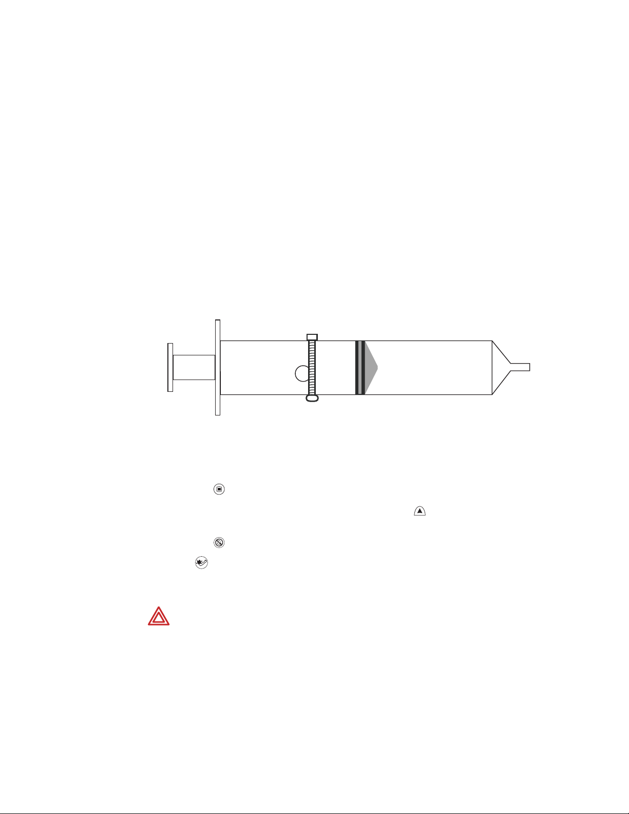
Characterization test
1. Attach a neonate hose (part 008-0265-01) to the NIBP fitting on the monitor.
2. Prepare the 60-mL syringe as follows, with reference to the illustration below:
a. Move the syringe plunger to the 35 mL line.
b. Drill a small hole (for example, 9/64 inch) through the syringe and the plunger
c. Insert a rod or bolt (for example, a 6-32 screw) through the hole so that the
The tests described in this section are to be performed only as part of a complete
functional verification procedure.
shaft, at a location between the plunger and the top of the syringe.
plunger cannot move, creating a constant volume in the syringe of 35 mL ± 2 mL.
Secure the rod or bolt so that it cannot fall out of the hole.
-- 60
--
-- 50
--
-- 40
--
-- 30
--
-- 20
--
-- 10
--
ml
3. Insert the tip of the syringe into the open end of the neonate hose. Verify that the fit
is tight and secure.
4. Set the monitor patient type to Adult, as follows:
a. Press once.
b. If the monitor is not already in Adult mode, press once or twice until Adult
appears in the message display.
c. Press .
5. Press .
6. Verify that the error code C03 appears in the message display within a few seconds.
WARNING If the error code C03 does not appear, characterize NIBP according
to the instructions presented on page 36, and then repeat the NIBP
characterization test.
WARNING Do not use the monitor if it does not pass the NIBP characterization
test. If the NIBP module is not properly characterized, the monitor could
overinflate a neonatal cuff, which could create a hazard for neonatal patients.
WARNING If you cannot characterize the NIBP module, remove the monitor
from service immediately and return it to Welch Allyn for service. (See “Returning
products” on page 6.)
Page 19

Service manual Functional verification 15
Leak test
This tests the NIBP system for abnormal leakage.
If the NIBP system is leaking, check for leaks in the external plumbing before opening the
case to look for internal leaks.
If you determine that any NIBP module component is causing abnormal leakage, you
must replace the NIBP module before returning the monitor to clinical use.
Caution Do not attempt component-level repair of the NIBP module. Any
change to the NIBP module requires that the monitor be returned to the factory
for NIBP module calibration.
1. Put the monitor in Service mode:
a. Power the monitor off.
b. Power the monitor on while pressing .
WARNING Do not connect the monitor to a patient while the monitor is in
Service mode. Overpressure detection is disabled while the monitor is in NIBP
test mode.
2. Attach a #1 neonatal cuff and hose to the monitor
Wrap the cuff securely around a solid cylindrical object of circumference between 1.6
and 1.9 inches (4.1 and 4.8 cm).
3. Press repeatedly until NIBP TEST appears in the message window and 0 is
displayed in the SYS and DIA windows.
Note
4. Press once to select 80 mmHg (10.7 kPa). The cuff inflates to approximately 115
Note
When you first enter the NIBP test mode, give the monitor about a minute to
initialize NIBP before you change the target test pressure.
When switching from one target pressure to the next, give the monitor time to
fully inflate and stop before you select the next target pressure.
In the NIBP test mode, press repeatedly to select the target NIBP test
pressure. The target pressure is displayed on the DIA LEDs. The measured
instantaneous pressure determined by the monitor is displayed on the SYS LEDs.
mmHg (15.3 kPa).
In the NIBP test mode, and especially at small test volumes, the pressure
achieved can vary significantly (30-40 mmHg or 4-5.3 kPa) from the target
pressure.
5. Wait 15 seconds, and note the current pressure.
6. Wait another 10 seconds and verify that the pressure has not dropped more than
8 mmHg (1.1 kPa) below the pressure noted in step 5.
If the pressure drop is greater than 8 mmHg (1.1 kPa), check the cuff, the hose, and all
external connections for leaks, and then repeat from step 3.
Page 20
16 Functional verification Welch Allyn VSM 300 Series
7. Press several times to select 0 mmHg (0 kPa). The valve opens to release
pressure.
8. Disconnect the neonate cuff.
Pressure calibration verification
This tests pressure readings on the monitor against a calibrated external pressure meter.
1. Put the monitor in Service mode:
a. Power the monitor off.
b. Power the monitor on while pressing .
WARNING Do not connect the monitor to a patient while the monitor is in
Service mode. Overpressure detection is disabled while the monitor is in NIBP
test mode.
2. Connect the monitor to an adult cuff or a 500 cc test volume, a pressure meter or a
manometer, and a pump bulb, as shown.
3. Press repeatedly until NIBP TEST appears in the message window and 0 is
displayed in the SYS and DIA windows.
Page 21

Service manual Functional verification 17
4. Press once to select 80 mmHg (10.7 kPa). The cuff quickly inflates to
approximately 80 mmHg (10.7 kPa), and then settles at a slightly lower pressure level.
Wait a few seconds for the pressure to stabilize.
5. Verify that the value displayed in SYS is within 3 mmHg (0.4 kPa) of the value
displayed on the digital pressure meter.
6. Press to select 150 mmHg (20 kPa) target pressure. The cuff quickly inflates to
approximately 150 mmHg (20 kPa), and then settles at a slightly lower pressure level.
Wait a few seconds for the pressure to stabilize.
7. Verify that the value displayed in SYS is within 3 mmHg (0.4 kPa) of the value on the
digital pressure meter.
8. Press to select 300 mmHg (40 kPa). The cuff quickly inflates to approximately 300
mmHg (40 kPa), and then settles at a slightly lower pressure level. Wait a few
seconds for the pressure to stabilize.
9. Verify that the value displayed in SYS is within 6 mmHg (0.8 kPa) of the value on the
digital pressure meter.
Valve and pump current, inflation, and deflation tests
Note
To test pump current
1. Put the monitor in Service mode:
2. Press repeatedly until NIBP TEST appears in the message window and 0 is
3. Press to select 0 mmHg (0 kPa) target pressure.
4. While watching the current meter, press to select 80 mmHg (10.7 kPa) target
5. Note the highest current reading during inflation.
6. While the pump is running, verify that the reading on the current meter is not more
Replace the internal battery with an external power supply. (See “Battery
substitution cable setup” on page 12.)
a. Power the monitor off.
b. Power the monitor on while pressing .
WARNING Do not connect the monitor to a patient while the monitor is in
Service mode. Overpressure detection is disabled while the monitor is in NIBP
test mode.
displayed in the SYS and DIA windows.
pressure.
than 750 mA above the current level noted in step 2 of the verification test (“Baseline
current draw” on page 13).
7. Press three times to select 0 mmHg (0 kPa) target pressure.
To test inflation
1. Press repeatedly until NIBP TEST appears in the message window and 0 is
displayed in the SYS and DIA windows.
Page 22

18 Functional verification Welch Allyn VSM 300 Series
2. Press once to select 80 mmHg (10.7 kPa).
3. Wait for the pump to start and stop.
4. Press once to select 150 mmHg (20 kPa).
5. Wait for the pump to start and stop.
6. Bleed the pressure to 0 by opening the relief valve on the bulb.
7. Close the relief valve on the bulb.
8. Have a timer ready.
9. Press once to select 300 mmHg (40 kPa), and immediately observe the
manometer.
10. As soon as the manometer reads 5 mmHg (0.67 kPa), start the timer.
11. When the manometer reaches 250 mmHg (33.3 kPa), stop the timer.
12. Verify that the elapsed time (step 11 minus step 10) is less than 8 seconds.
To test deflation
1. If the pressure has dropped more than 10 mmHg, use the pump bulb to raise it to 300
mmHg ± 5 mmHg.
2. While the pressure is still at approximately 300 mmHg (as shown by the manometer
and the SYS window), press once to select 0 mmHg, and immediately start the
timer.
3. After 10 seconds, verify that the manometer reads less than 15 mmHg.
If you are doing the NIBP overpressure test, skip to “Overpressure tests (optional)”
on page 18.
4. Disconnect the hose from the monitor.
Overpressure tests (optional)
Note
These tests demonstrate that:
Redundant circuitry in the VSM 300 series monitor guarantees that the bloodpressure cuff cannot overinflate.
The allowable cuff pressure and the overpressure cutoff are controlled by
software. A software failure (a defective PROM) would generate a checksum
error, disabling monitor operation and setting it in a safe mode.
• the monitor cannot exceed the maximum allowable cuff pressure for adults (280
mmHg), pediatrics (200 mmHg), and neonates (141 mmHg)
• the overpressure cutoff feature shuts down the pump and dumps pressure before
the pressure reaches 330 mmHg (44 kPa)
To verify maximum allowable cuff pressure for NIBP version 3.20.00
1. Assemble one of the test setups illustrated on page 16, using an adult cuff or cuff
simulator.
Page 23

Service manual Functional verification 19
2. Turn on the monitor.
3. Set the monitor to ADULT mode.
a. Press once.
b. Press repeatedly until ADULT appears.
4. Set the inflation target pressure to 270 mmHg (36 kPa).
a. Press repeatedly until TARGET PRESSURE appears in the display window.
b. Press repeatedly as needed to set the target pressure (displayed in the SYS
window) to 270 mmHg (36 kPa).
5. Press to start the pump.
The pressure reaches approximately 270 mmHg (36 kPa), the pump shuts off, and the
pressure begins stepping down.
6. Carefully squeeze the pump bulb to raise the pressure to 280 mmHg (37.3 kPa).
• The dump valve opens and quickly drops the pressure to approximately 0.
• The monitor displays C10 to indicate that an overpressure event has occurred.
7. Set the monitor to PEDIATRIC mode.
8. Set the inflation target pressure to 170 mmHg (22.7 kPa).
9. Raise the pressure to 200 mmHg (26.7 kPa).
a. Press and wait for the pressure to reach 170 mmHg (22.7 kPa). The pump
shuts off and the pressure reading starts stepping down.
b. Carefully squeeze the pump bulb to raise the pressure to 200 mmHg (26.7 kPa).
• The dump valve opens and quickly drops the pressure to approximately 0.
• The monitor displays C10 to indicate that an overpressure event has occurred.
10. Replace the adult cuff with a #1 neonate cuff, and wrap the neonate cuff securely
around a solid cylindrical object with circumference between 1.6 and 1.9 inches (4.1
and 4.8 cm).
11. Set the monitor to NEONATE mode.
12. Set the inflation target pressure to 132 mmHg (17.6 kPa).
13. Raise the pressure to 141 mmHg.
a. Press and wait for the pressure to reach 132 mmHg (17.6 kPa). The pump
shuts off and the pressure reading starts stepping down.
b. Carefully squeeze the pump bulb to raise the pressure to 141 mmHg (18.8 kPa).
• The dump valve opens and quickly drops the pressure to approximately 0.
• The monitor displays C10 to indicate that an overpressure event has occurred.
To verify overpressure cutoff for NIBP versions 4.20.00 and later
This test demonstrates that the overpressure cutoff feature prevents pressure from rising
fast enough to exceed the cutoff pressure (295 to 330 mmHg, or 39.3 to 44.0 kPa) before
the pump stops and the dump valve and the bleed valve open.
Page 24

20 Functional verification Welch Allyn VSM 300 Series
When the overpressure cutoff triggers, the pump stops, the dump and bleed valves open,
and the monitor displays E40. Any subsequent button press shuts off the monitor.
Note
Due to NIBP implementation differences, this test does not verify overpressure
cutoff in earlier NIBP versions.
In those versions, due to a longer software delay in activating the cutoff function,
the normal overpressure cuff pressure is exceeded before the overpressure
cutoff safety triggers. If the normal overpressure-detection algorithm were to fail,
the overpressure cutoff safety function would trigger immediately.
1. Restart the monitor.
2. Set the monitor to ADULT mode.
3. Set the inflation target pressure to 270 mmHg (36.0 kPa).
4. Increase the inflation rate, causing the overpressure cutoff to stop the pump and
open the bleed and dump valves.
a. Start the pump.
b. When the pressure (SYS window) reaches approximately 230 mmHg (32.4 kPa),
very rapidly squeeze the pump bulb while observing the digital pressure meter.
Assuming that you squeeze the bulb rapidly enough to reach the trigger threshold
and activate the overpressure cutoff:
• The pressure does not exceed 280 mmHg.
• The dump valve and bleed valve open, dropping the pressure to
approximately 0.
• E40 appears in the Sys window.
• Pressing any button causes the monitor to shut down.
5. Disconnect the test setup from the monitor.
If you executed this test as part of the functional verification procedure, proceed to...
• “Printer” on page 21.
• If the monitor has no printer, “SpO2” on page 23.
• If the monitor has no SpO2 option, “Temperature” on page 25.
• If the monitor has no temperature option, “Nurse call” on page 27.
Page 25

Service manual Functional verification 21
Printer
Note
1. Put the monitor into Service Mode.
2. Verify that the printer has paper.
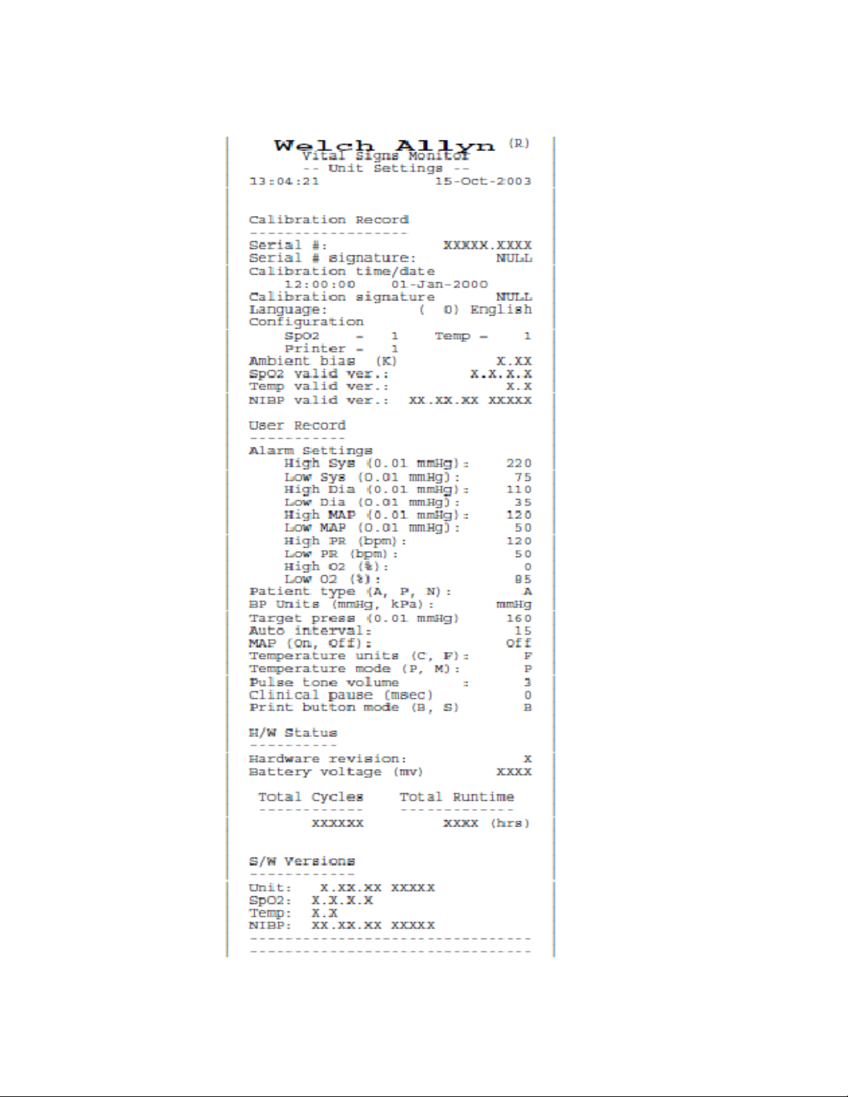
3. Press . Verify that a settings report prints, and that it contains no printed anomalies
Note
Note
This test is to be performed only as part of a complete functional verification
procedure.
and no missing or faded sections.
With a new roll of paper, the first line might be faded. This does not indicate a
problem.
The settings report (as shown in the example below) contains a calibration record,
user record, hardware status record, and software versions record.
• The calibration record includes manufacturing configuration data: monitor
serial number, set parameters, and language.
• The user record includes user-configurable settings: alarm limits, patient type,
parameter modes/units, auto interval, tone volume, and others.
• The hardware status record shows the hardware revision number, the battery
voltage level, the total number of NIBP monitoring cycles completed on the
monitor, and the total number of hours of operation of the monitor.
• The software versions record indicates the software version numbers of the
main board, SpO2and Temperature options (if present), and NIBP.
4. After 2 seconds of printing, verify that the current draw is no more than 2.5A above
the baseline current recorded in step 2 of the verification test “Baseline current
draw” on page 13.
5. Exit the Service Mode.
Page 26
22 Functional verification Welch Allyn VSM 300 Series
Page 27

Service manual Functional verification 23
SpO
2
Note
Perform one of the following three SpO2tests.
The tests described in this section are to be performed only as part of a complete
functional verification procedure.
Testing the monitor only (Nellcor SpO2)
Use this procedure to test only the monitor SpO2function.
1. Power the monitor off.
2. Connect the Nellcor SRC-MAX SpO2functional tester to the SpO2input connector
through a Nellcor DEC-8 extension cable.
3. Power the monitor on.
Note
4. Verify the following on the SRC-MAX:
In the following tests, if the SRC-MAX defaults are outside the monitor alarm
limits, readjust the limits or silence the alarms.
• All of the monitor LEDs flash: left panel, center panel, right panel.
• SRC-MAX initializes to a default condition where the four test parameter LEDs are
lit closest to their selector buttons
• The default pulse rate is 60 bpm and the default SpO2is 75%
5. Give the monitor up to 30 seconds to stabilize, and verify a displayed pulse rate of
60 ± 3 bpm and a displayed SpO2of 75 ± 3%.
6. Set the SRC-MAX pulse rate to 200 bpm.
7. Give the monitor up to 30 seconds to stabilize, and verify a displayed pulse rate of
200 ± 3 bpm.
8. Switch the SRC-MAX SpO2saturation percentage to 90.
9. Give the monitor up to 30 seconds to stabilize, and verify a displayed SpO2saturation
level of 90 ± 3%.
10. Disconnect the SRC-MAX.
Testing the monitor only (Masimo SpO2)
Use this procedure to test only the monitor SpO2function.
1. Power the monitor off.
2. Connect the Masimo Tester REF 1593.
3. Power the monitor on.
4. Give the monitor up to 30 seconds to stabilize, and then verify a displayed pulse rate
(from SpO2) of 61 bpm ± 1 bpm and a displayed saturation of 81% ± 3%.
Page 28

24 Functional verification Welch Allyn VSM 300 Series
Testing the sensor with the monitor
Use this procedure to test the monitor SpO2function while verifying a sensor.
1. Connect an SpO
2. Set the BioTek Index2 SpO
sensor to the simulator optical finger and to the monitor.
2
simulator as follows:
2
SpO2manufacturer type Nellcor (MP-506A or Nell-3A)
Masimo (MS-11)
% SpO
2
94
Rate 60 (Motion Artifact not selected)
3. Wait for the monitor display to stabilize.
4. Verify an SpO2saturation level of 94 ± 4.
5. Verify that the monitor displays a pulse rate of 60 ± 4.
Page 29

Service manual Functional verification 25
Temperature
Note
Perform one of the following temperature tests.
The tests described in this section are to be performed only as part of a complete
functional verification procedure.
Testing the monitor only
Use this procedure to test only the temperature function.
1. With monitor power on and with the temperature probe in the well, disconnect the
probe cable from the temperature input connector on the rear of the unit.
2. Connect the Welch Allyn Sure Temp Plus temperature test key (06138-000) to the
temperature input connector.
3. Remove the probe from the well.
4. Verify that the displayed temperature is 97.3 ± 0.2 F (36.3 ± 0.1 C).
Testing the probe with the monitor
Use this procedure to test the temperature function while verifying the
temperature probe.
1. If the Welch Allyn Calibration Tester is not already warmed up, warm it up as follows:
a. Set the tester temperature to the following temperature:
Model Temperature
9600 96.4 °F (35.8 °C)
9600 Plus 96.8 °F (36.0 °C)
b. Plug the power adapter into the tester; wait (up to 15 minutes) until the tester
‘ready’ indicator light is on continuously.
2. Set the monitor temperature mode to Monitored.
3. Insert the temperature probe (without probe cover) into the small thermometer hole
on the dry-heat well of the tester.
4. Wait two minutes and verify that the reading displayed on the monitor is as follows:
Model Temperature
9600 96.4 °F ±0.4 °F (35.8 °C ±0.2 °C)
9600 Plus 96.8 °F ±0.4 °F (36.0 °C ±0.2 °C)
5. Switch the tester to the following temperature and wait about five minutes for the
‘ready’ indicator to light.
Model Temperature
9600 106.0 °F (41.1 °C)
9600 Plus 105.8 °F (41.0 °C)
Page 30

26 Functional verification Welch Allyn VSM 300 Series
6. Verify that the reading displayed on the monitor is as follows:
Model Temperature
9600 106.0 °F ±0.4 °F (41.1 °C ±0.2 °C)
9600 Plus 105.8 °F ±0.4 °F (41.0 °C ±0.2 °C)
7. Remove the probe from the tester and replace it in the probe well.
8. Disconnect the tester.
Page 31

Service manual Functional verification 27
Nurse call
Note
Relay verification
With reference to the drawing and table below, use an ohmmeter to check the contact
resistance at the output pins of the Nurse Call connector, while the monitor is in the alarm
state and while the monitor is out of the alarm state.
When the Nurse Call verification is done, disconnect the Nurse Call cable and turn off the
monitor.
The tests described in this section are to be performed only as part of a complete
functional verification procedure.
1 (Black)
Normally Open
2 (Red) Arm
Pins Resistance
1-2 > 1 M <1
2-3 < 1 >1M
4 (not connected)
3 (Green)
Normally Closed
(Alarm OFF)
30V , 1A Max.
Resistance
(Alarm ON)
Putting the monitor into the alarm state
To create an alarm condition for testing the Nurse Call relay, follow these steps.
1. Press repeatedly until INTERVAL ST appears in the message display.
2. Wait for the pump to charge twice (about 10 seconds), and verify that error code C04
appears in the SYS display.
3. Verify that the Nurse Call circuit is shorted. (Refer to the table shown above.)
4. Press .
5. Verify that the Nurse Call circuit is open. (Refer to the table shown above.)
6. To exit the alarm state, press repeatedly until INTERVAL 15 appears in the
message display, and then press .
Page 32

28 Functional verification Welch Allyn VSM 300 Series
Battery
Note
This test is to be performed only as part of a complete functional verification
procedure.
1. With the monitor power off, disconnect the battery substitution-cable connector.
2. Install and connect the battery.
3. Connect the AC power adapter to the monitor.
4. Verify that the AC mains indicator is illuminated on the monitor front panel.
The indicator could be flashing or steady, depending on the state of the battery.
flashing indicates that the battery is charging; steady indicates that the
battery is charged to at least 90% capacity.
5. Charge the battery for a minimum of 12 hours (until stops flashing).
6. Disconnect the AC power adapter.
7. Turn the monitor on and set it up as follows:
NIBP Auto Interval OFF
Printer, if present OFF (not printing)
sensor
SpO
2
(if SpO
option is present)
2
Temperature probe
(if temperature option is present)
Disconnected
Either connected or disconnected
8. Note the time and let the monitor run until low battery ( flashing) is indicated.
(Run time for a new, fully charged battery is at least 12 hours.)
9. Charge the battery for a minimum of 12 hours (until stops flashing).
10. Disconnect the ac power adapter.
11. Start the monitor in Service Mode.
12. Press repeatedly until “Battery: X.XXV appears in the message window.
13. Verify that the voltage is
Patient isolation test
Note
Patient isolation test - overview
To verify proper patient isolation, it is important to run this test following any procedure in
which the monitor is opened.
This test is to be performed only as part of a complete functional verification
procedure.
WARNING Failure to run the dielectric test when indicated could cause serious
injury to patients, and could lead to damage to the monitor.
6.10 V.
Page 33

Service manual Functional verification 29
The patient isolation test requires an AC Withstand voltage high potential (hi-pot) tester,
such as the AR 3605 or equivalent. If this equipment is not available, Welch Allyn can
perform the patient isolation test for you quickly, for a nominal fee.
WARNING The patient isolation test involves exposure to extremely high
voltages, and is therefore extremely hazardous.
WARNING Always follow the tester manufacturer’s operation instructions
exactly. Failure to perform this test properly can result in serious injury or death.
WARNING This test must be performed by qualified service personnel only.
WARNING Run this test only on an insulated table top, and away from other
people and equipment.
Test connections
Cable Monitor connection Hi-pot tester connection
Connector/cable Connect to Wiring Connect to
DC Input Switchcraft 760
SpO
2
(Nellcor)
SpO
2
(Masimo)
RS232 RJ45/standard patch cable Communication
Nurse Call Welch Allyn Nurse Call
0.100” ID
0.218” OD
Nellcor D-connector (DEC-8
or other
OXI-MAX equivalent)
Masimo 14-pin mini
D-connector
cable 008-0634-XX (Uses
Lemo connector
PAB.MO.4GLAC397.)
DC Input Connector Both wires connected together
Input Connector All wires connected together
SpO
2
Input Connector All wires connected together
SpO
2
Connector
Nurse Call Connector All wires connected together
and terminated appropriately
for your hi-pot tester
and terminated appropriately
for your hi-pot tester
and terminated appropriately
for your hi-pot tester
All wires connected together
and terminated appropriately
for your hi-pot tester
and terminated appropriately
for your hi-pot tester
Return
High Voltage
High Voltage
High Voltage
High Voltage
Patient isolation test - procedure
1. Set up the test parameters on the AC Withstand Voltage Tester as follows:
Note
Parameter Specification Parameter Specification
Voltage 1500 Vac Ramp Down 0
Maximum Limit 2.50 mA Arc Sense 0
Minimum Limit 0.038 mA Frequency local line (50 Hz or 60 Hz)
Ramp Up 5.0 S Continuity Off
Dwell 5.0 S Connect Off
Delay 0
Note
Refer to the tester manufacturer’s operation manual for complete details on
setup and use.
To create test cables for this procedure, see the previous table.
Page 34

30 Functional verification Welch Allyn VSM 300 Series
2. Connect the hi-pot DC input test cable between the return jack on the tester and the
DC input connector of the monitor.
3. Test isolation between the Nurse Call and DC input:
a. Connect the hi-pot Nurse Call test cable between the nurse call connector and
the high-voltage jack on the hi-pot tester.
b. Press the test button to run the AC withstand voltage test.
c. Verify that the monitor passed the test. (If the input current never exceeds 2.50
mA, the shielding is sufficient.)
d. Remove the Nurse Call test cable.
4. Test isolation between RS232 and DC input:
a. Connect the hi-pot RS232 test cable between the RS232 connector and the
high-voltage jack on the hi-pot tester.
b. Press the test button to run the AC Withstand Voltage test.
c. Verify that the monitor passed the test. (If the input current never exceeds 2.50
mA, the shielding is sufficient.)
d. Remove the hi-pot RS232 test cable from the RS232 connector and the hi-pot
tester.
5. Test the isolation between SpO2 and DC input:
a. Connect the SpO
test cable between the SpO2connector and the high-voltage
2
jack on the hi-pot tester.
b. Push the test button to run the AC Withstand Voltage test.
c. Verify that the monitor passed the test. (If the input current never exceeds 2.50
mA, the isolation is sufficient.)
d. Remove the SpO2test cable.
6. Remove the DC input test cable.
Page 35

Service manual Functional verification 31
Checklist and test results report form
Use a copy of this form to track your progress through the functional verification.
Fail
Pass
(or
Test Result
Battery charging
Power-on self-test
Beeper
Monitor-off current (mA):
Init/idle current (mA):
Baseline current (mA):
Battery voltage Monitor (V): DMM (V):
NIBP characterization test
NIBP verification
Pressure leakage Before (mmHg): After (mmHg):
Pressure accuracy 80 mmHg SYS: Manometer:
150 mmHg SYS: Manometer:
300 mmHg SYS: Manometer:
Valve/pump current Valve/Pump (mA)
- Baseline (mA)
Difference (mA)
Inflation Elapsed time (sec):
Deflation Manometer reading (mmHg):
Max allowable cuff pressure
Adult mmHg kPa
Pediatric mmHg kPa
Neonate mmHg kPa
Overpressure cut-off (Pass-Fail)
Printer current Peak (mA):
SpO
2
Temperature Fahrenheit: Celsius:
Nurse call relay pins 1-2 Alarm () No Alarm ()
Battery charge time
Battery discharge time
Battery voltage volts
Saturation (%): Pulse (bpm):
pins 2-3 Alarm () No Alarm ()
N/A)
Monitor serial #:
Tested by:
Test date:
Page 36

32 Functional verification Welch Allyn VSM 300 Series
Here is an example of verification results for a typical monitor.
Pass
Test Result
(or N/A)
Battery charging charge symbol lit
Power-on self-test normal
Beeper audible
Monitor-off current (mA): 0
Init/idle current (mA): 467
Baseline current (mA): 199
Battery voltage Monitor (V): 5.94 DMM (V): 5.95
NIBP characterization test C03
NIBP verification
Pressure leakage Before (mmHg): 100 After (mmHg): 99
Pressure accuracy 80 mmHg SYS: 73 Manometer: 72
150 mmHg SYS: 142 Manometer:140
300 mmHg SYS: 290 Manometer: 286
Valve/pump current Valve/Pump (mA)
Baseline (mA)
Difference (mA)
Inflation Elapsed time (sec): 6
560
199
361
Deflation Manometer reading (mmHg): 0 (3 sec)
Max allowable cuff pressure
Adult (280 [37.3]) 280 mmHg kPa
Pediatric (200 [26.7]) 200 mmHg kPa
Neonate (141 [18.8]) 141 mmHg kPa
Overpressure cut-off (Pass-Fail)
Printer current Peak (mA): 940
SpO
2
Saturation (%): 90 Pulse (bpm): 200
Temperature Fahrenheit: 105.9 Celsius:
Nurse call relay pins 1-2 Alarm () >1M No Alarm () <1
pins 2-3 Alarm () <1 No Alarm () >1M
Battery charge time 12.5 h
Battery discharge time 19 h
Battery voltage 6.40 volts
Fail
Monitor Serial #: JA036582
Tested by: RJ
Test date: 8/30/2007
Page 37

33
4
Troubleshooting and repair
Troubleshooting chart
This troubleshooting chart includes error codes related to possible internal failures. Based
on the observed symptom, perform suggested actions one at a time from top to bottom.
To reduce repair costs, determine whether the symptom still exists, by performing the
device functional verification after each action. If other error codes appear, refer to the
directions for use for information on the cause and suggested remedy for those errors.
Caution Replace parts, components, or accessories only with parts supplied or
approved by Welch Allyn. The use of any other parts can lead to inferior monitor
performance and will void the product warranty.
Symptom Possible cause Suggested action
Monitor does not power up. Power adapter not powered.
Wrong power adapter.
Defective power adapter.
Battery is fully discharged.
Verify that the power adapter is plugged into the
AC source and the monitor.
Use the right power adapter.
Replace the power adapter.
Run the battery verification test; replace the
battery if necessary.
Battery fuse open.
Battery run time is low. Defective battery Replace the battery.
NIBP air leak exceeds
specified limits.
Repeated C03 error code. NIBP internal tubing is kinked. Route tubing properly through the monitor.
Repeated C04 error code. NIBP internal tubing is
Leaky check valve. Replace the check valve.
Leaky tubing or connector. Replace the tubing or the connector.
Leaky pump. Replace the pump.
Leaky bleed or dump valve. Replace the POEM2 NIBP manifold (if a POEM2
disconnected.
Faulty NIBP module.
Replace the battery.
module is installed) or replace NIBP module.
Warning: Always characterize NIBP after
replacing any NIBP component. (See “NIBP
characterization” on page 36.)
Properly connect the NIBP tubing.
Replace the NIBP module.
Warning: Always characterize NIBP after
replacing any NIBP component. (See “NIBP
characterization” on page 36.)
Page 38

34 Troubleshooting and repair Welch Allyn VSM 300 Series
Symptom Possible cause Suggested action
Repeated C07 error code. Incompatible SpO
Improperly connected SpO
Faulty SpO
Faulty SpO
Repeated C20 temperature
error code.
Probe well is not installed in the
probe-well housing.
Faulty probe.
Faulty temperature board.
sensor.
2
board.
2
sensor.
2
sensor.
2
Use a compatible sensor.
Properly connect the sensor cable.
Replace the sensor.
Replace the SpO2board.
Install the probe well in the probe-well housing.
Replace the probe.
Replace the temperature board. For details, see
order number 21327-1000 in “Temperature option”
on page 92.
Error code E30 PROM is corrupt. Return the monitor to an authorized service center
for PROM programming.
Error code E31 RAM test failure. Cycle the power. If the error persists, return the
monitor to an authorized service center for
replacement of the main board.
Error code E32 Factory data failure. Return the monitor to an authorized service center
for replacement of the main board.
Error code E33 User data error. Cycle the power to reset all user settings to default
values.
Error code E34 A/D converter failure. Cycle the power. If the error persists, return the
monitor to an authorized service center for
replacement of the main board.
Error code E35 SpO
module failure. Verify all cable connections, and then cycle the
2
power. If the error persists, replace the SpO
board. Use the service utility to verify compatibility.
2
Error code E36 Faulty probe. Replace the temperature probe with a known
good probe.
Temperature module failure. Verify all cable connections, and then cycle the
power. If the error persists, replace the
temperature board, Use the service utility to verify
compatibility.
Error code E37 Printer failure. Verify all cable connections, and then cycle the
power. If the error persists, replace the printer
module. Verify that the paper guide and sensor are
properly attached to the printer chassis.
Error code E38 Error E38 always occurs when the
Cycle the power, and then reset the date and time.
monitor is first powered after a
battery has been connected.
Real-time clock failure.
Cycle the power. If the error persists, return the
monitor to an authorized service center for
replacement of the main board.
Error code E40 NIBP module failure. Characterize NIBP. (See “NIBP
characterization” on page 36.) If the error
persists, return the monitor to Welch Allyn for
service/
Error code E41 NIBP module failure. Verify all cable connections, and then cycle the
power. If the error persists, replace the NIBP
module.
Warning: Always characterize NIBP after
replacing any NIBP component. (See “NIBP
characterization” on page 36.)
Error code E44 POST queue full. Cycle the power. If the error persists, return the
monitor to an authorized service center for
replacement of the main board.
Page 39

Service manual Troubleshooting and repair 35
Symptom Possible cause Suggested action
Missing LED display. LED failure on the display board. Replace the display board.
Erroneous LCD characters. LCD partially connected. Fully connect the LCD to the main board.
Buttons on the right side of
the monitor require noticeably
more pressure to actuate.
Screws attaching the display
board to the front panel are loose.
Tighten the screws.
Do not exceed 4 in-lbs.
Page 40

36 Troubleshooting and repair Welch Allyn VSM 300 Series
Requirements for module-level repair and replacement
Note
All repairs to a monitor under warranty must be performed at an authorized Welch
Allyn service center.
Activity Recommended action
Update the software Use the VSM Service Utility (810-1784-XX).
Replace the main board Return the monitor to an authorized service center.
Replace the NIBP module. Replacement procedure beginning on page 55.
Replace the SpO
Replace the SpO2side panel. Replacement procedure beginning on page 55.
Replace the temperature board. Replacement procedure beginning on page 55.
Replace the printer. Replacement procedure beginning on page 55.
Replace the front panel. Replacement procedure beginning on page 55.
board Replacement procedure beginning on page 55.
2
Perform a complete functional verification (page 9).
Warning: Always characterize NIBP after replacing any NIBP
component. (See “NIBP characterization” on page 36.)
Perform a complete functional verification (page 9).
Perform a complete functional verification (page 9).
Perform a complete functional verification (page 9).
Perform a complete functional verification (page 9).
Perform a complete functional verification (page 9).
NIBP characterization
WARNING Whenever any component of the NIBP assembly (pump, air filter,
check valve, tubing, or NIBP board) is replaced, the NIBP module must be
characterized before the monitor is returned to service.
WARNING If the NIBP module is not properly characterized, the NIBP cuff could
overinflate, which could be hazardous to neonatal patients.
The Welch Allyn Monitor Service Utility facilitates this characterization procedure. For
more information, see “Characterizing NIBP” on page 41.
Page 41

Service manual Troubleshooting and repair 37
Welch Allyn monitor service utility
Overview
The Welch Allyn Monitor Service Utility is a software tool for use, with the VSM 300
Series service manual, by biomedical technicians, clinical engineers, and other qualified
service personnel, to update and repair VSM 300 Series monitors.
The utility supports the following service functions:
• Characterize the VSM 300 NIBP module
• View, read, print VSM 300 logs
• Update VSM 300 software
• Enable the monitor to accept updated NIBP, SpO2and temperature modules
Where to find information:
Using the utility Utility help files
Servicing the monitor This document (Vital Signs Monitor 300 Series
Service Manual).
Supported SW and HW versions CD release notes
The utility includes the following upgrades, which are for the VSM 300 Series only:
• NIBP module software
• Main board software
Note
Note
Note
Note
Note
This upgrade procedure might return monitor user settings to the factory defaults.
Refer to the service manual for information about factory default values.
Monitors with serial numbers JA020000 to JA044073 were shipped with the
NIBP version 3.20.00 software installed.
This utility is not required when replacing SpO2modules with the same firmware
version.
This utility is not required when replacing SureTemp modules with the same
firmware version. Monitors with serial numbers JA020320 and greater were
shipped with SureTemp version 1.2.
Nellcor and Masimo SpO2modules cannot be interchanged.
Note
Note
Monitors with serial numbers JA030012 and greater were shipped with the
Monitor Main version 1.20.00 software installed.
Monitors with NIBP software version 4.20.00 contain the POEM2 NIBP module.
NIBP software version 4.20.00 is incompatible with NIBP POEM1 modules
running version 3.20.00 and older. NIBP module software older than version
4.10.00 is incompatible the POEM2 module. Monitors with serial numbers above
JA044073 were shipped with software version 4.20.00 or greater.
Page 42

38 Troubleshooting and repair Welch Allyn VSM 300 Series
Required equipment
810-1784-xx Vital Signs Monitor 300 Series Software Upgrade Tool CD-ROM
008-0842-xx Vital Signs Monitor 300 Series serial cable
PC with the following:
• Windows XP SP2 or Windows 2000 SP4 operating system
• Intel Pentium IV CPU, or equivalent
• 256 MB RAM memory
• CD-ROM drive
• At least 20 MB available hard-disk space
• Available printer
• Available RS-232 serial communications port, 9-pin, D-style (If no RS-232 port is
available but a USB port is available, you must have a USB-to-serial (DB9) adaptor (not
supplied). For Windows 2000 and XP operating systems, the supported adapter is
KEYSPAN USB serial adapter USA-19HS.)
Warranty service
All repairs on products under warranty must be performed or approved by Welch Allyn.
Refer all warranty service to Welch Allyn Factory Service or another authorized Welch
Allyn Service Center.
Caution Unauthorized repairs will void the product warranty.
Non-warranty service
Welch Allyn Factory Service and authorized Service Centers support non-warranty repairs.
Contact any Welch Allyn regional service center for pricing and service options. Welch
Allyn offers modular repair parts for sale to support non-warranty service. This service
must be performed only by qualified customer biomedical/clinical engineers using the
VSM service manual (810-1651-XX).
Note
Using the procedure described in this document to upgrade the NIBP software to
version 3.20.00 does not void the warranty.
Installation and setup
Note
To install the utility
1. Insert the Service Utility distribution disk (810-1784-xx) into the CD-ROM drive of the
Remove any previous versions of the service utility before installing this version.
(See “Uninstalling older versions of the utility” on page 53.)
installation PC.
2. Install the utility software.
a. If Autorun is enabled on the CD-ROM drive, an installation program starts. Follow
the on-screen installation instructions.
b. If Autorun is not enabled, use Windows Explorer to navigate to the CD-ROM drive
and run setup.exe. Follow the on-screen installation instructions.
Page 43

Service manual Troubleshooting and repair 39
The default utility installation is into:
C:\Program Files\Welch Allyn\Service Tool\VSM 300.
To set up the utility
1. Connect the AC power adapter to the monitor. (Do not turn the monitor on.)
2. Connect the RJ-45 connector on the serial cable to the monitor.
3. If you are not using a USB-to-serial adapter, skip to step 8.
4. Follow the USB-to-serial adapter manufacturer’s instructions to load the USB drivers.
5. Connect the serial cable DB-9 connector to the DB-9 connector on the adapter.
6. Connect the USB connector to the USB port on the PC.
7. Skip to step 9.
Serial (RJ45)
connector
AC power
connector
USB port
Serial-to-USB
adapter
Monitor AC
power cord
Monitor AC
power adapter
USB cable
Serial cable
DB9 connector
8. Connect the DB-9 connector on the serial cable to the serial port on the PC.
9. Start the utility:
Start > Programs > Welch Allyn > Service Tool - VSM 300
10. Open the Options menu and select settings. If the status panel in the lower left
corner displays “VSM 3 Available”, then the utility has connected to the VSM; skip to
step 12.
11. Select the com port assigned to the serial port used to connect to the monitor.
12. Disable Log I/O to file.
Page 44

40 Troubleshooting and repair Welch Allyn VSM 300 Series
Note
If Log I/O to file is enabled, the utility captures all communications between the
VSM and the utility in the file io.log. This file continues to grow until the
communications link is broken, because the utility is continuously checking for the
presence of the VSM.
The utility overwrites io.log each time the service utility is started.
Here, the serial port (Communications Port) is configured to COM1 and the Keyspan
USB adapter is configured to COM4.
Note
If the utility displays “VSM3 not responding”, cycle the power to the monitor.
If the com port cannot be found in the Settings dialog, use the Device Manager to
configure the port.
To open the Device Manager
1. Start > right-click My Computer > Properties > Hardware >Device Manager.
2. Click Ports (COM & LPT) to expand the list.
Page 45

Service manual Troubleshooting and repair 41
To configure to a different COM port
1. Right-click on the port you want.
2. Select Properties.
3. Select Port Settings.
4. Click Advanced.
5. Select a new COM Port Number.
The port settings for the Keyspan adapter are explained in the documentation included
with the device. Keyspan provides an assistant to configure and diagnose the USB-toserial adapter. Access the assistant from Port Settings in the Device Properties dialog.
The VSM uses these default settings:
• 9600 bits per second
• 8 data bits
• no parity
• 1 stop bit
• no flow control
Service procedures
Characterizing NIBP
This operation trains the NIBP module to properly account for the volumes of internal and
external tubing when the pump is running.
WARNING You must characterize NIBP after replacing any NIBP components:
pump, tubing, air filter, check valve, or NIBP module. Failure to properly
characterize NIBP can lead to injury of neonatal patients.
Page 46

42 Troubleshooting and repair Welch Allyn VSM 300 Series
To characterize NIBP
1. Select Characterize NIBP. The utility displays the message "Choose Start to begin
characterization".
2. Click Start, and follow the on-screen instructions. The utility attempts to place the
monitor in the correct state for characterization:
• The monitor is turned off.
• The monitor, operating on charger power, supports communication between the
utility and the NIBP module.
3. Connect a 96-inch neonatal cuff hose (008-0265-XX) as indicated.
4. Remove the cuff.
5. Block (with a thumb, for example) or otherwise plug the free end of the tubing.
6. Click Next to initiate NIBP characterization. Within a few seconds, the message
"Success - Result not yet saved" and "Choose Next to save this value to EEPROM"
appear.
7. Click Next. The utility displays details from the VNRAM write process, followed by
the message "Please wait while the module reboots”. The reboot takes several
seconds. When it is complete, the message "Characterization is complete" appears.
8. Click Finish to clear the display and return the utility to the ready state.
Viewing, saving, and printing logs
To support troubleshooting and service, the VSM 300 maintains an Event Log, a Debug
Log, and a Cal & User Log. All can be viewed, saved and printed.
• The Event Log provides a detailed summary of the most recent operations
performed, up to the maximum log size.
Page 47

Service manual Troubleshooting and repair 43
• The Debug Log lists the most recent warning conditions that have occurred, up to
the maximum log size.
When the Event and Debug Logs reach maximum size, new data overwrites the oldest.
• The Calibration & User Log provides the following categories of information:
• calibration
• user-configuration
• run-time and cycle count
• software versions of all modules
Note
Note
Large log files can take several minutes to load.
The item counter, located on the right side below the radio buttons, sometimes
stops counting until all items have been retrieved from the monitor.
To view the log files
1. Click View Logs to access the logs.
2. Under Display, choose the desired log to load and view in the window.
To save the log files
1. Under Display, choose the desired log to save.
2. Click Save.
3. Navigate to the folder where the file will be saved.
4. Name the file.
5. Click Save.
To print the log files
1. Under Display, choose the desired log to print.
2. Click Print.
3. Select the printer and the print parameters.
4. Click Print.
Note
Screen images shown are samples only. Actual screens vary with each release.
Page 48

44 Troubleshooting and repair Welch Allyn VSM 300 Series
Event Log
Debug Log
Page 49

Service manual Troubleshooting and repair 45
Cal & User Logs
Update Monitor Software
The Update Monitor tab displays installed (Installed Ver) and available (Update Ver)
versions for the Monitor Boot, Main, and NIBP module software. If the monitor has an
optional SpO2or temperature module, the firmware versions are displayed. Update status
is shown for each, indicating whether an update is available for those versions that can be
updated.
If the version installed on the monitor is newer than what the utility supports, the status
displays “Not supported”. Contact Welch Allyn Technical Service to obtain an updated
version of this utility.
The status also indicates whether the installed software and firmware versions are
compatible with the update versions offered. The program checks for compatibility within
the module as well as compatibility between modules. If any of the software or firmware
is incompatible with the available updates the update button will not be active.
The SpO2and temperature module firmware can only be updated by replacing the
hardware modules. If the NIBP, SpO2or temperature module has been replaced with a
different version, the installed version for the new module is shown in orange.
The monitor hardware module field Installed Ver reports the mainboard hardware version.
The hardware version is included to prepare for the eventual possibility that incompatible
versions might someday be introduced. All VSM mainboards have HW code 0. No
incompatibilities currently exist between versions of the board.
Page 50

46 Troubleshooting and repair Welch Allyn VSM 300 Series
Update the Monitor
To minimize the possibility of interruption during the update:
• Do not run other applications on the PC during this process.
• Do not disconnect the monitor from the AC power adapter or the computer until
• Set the Power scheme on the PC to Always On to prevent it from turning off the
• Make sure the PC and the VSM are connected to a stable power source.
• Do not connect power cords to switched outlets.
• Do not connect power cords where they may be inadvertently disconnected.
If the update does not complete, the VSM reports an E40 error. Reinstalling the software
might result in a recovery.
If the installed software is current:
Caution If the update is interrupted, the VSM monitor might be left in an
unusable state.
Finished is clicked and Update Monitor has been refreshed.
monitor or hard disk and going into standby or hibernation mode.
Caution This upgrade procedure might return monitor user settings to the
factory defaults. To create a record of the current settings, select View Logs,
click Cal & User Logs, and save the current log.
• Update is grayed out.
• Update Status is “Up to date”.
• Upload Status is blank.
Page 51

Service manual Troubleshooting and repair 47
If updates are available, Update Status is either “Update required” or “Update
Recommended”.
1. Connect the monitor to the AC power adapter and to the PC.
2. Start the utility.
3. Select Update Monitor.
4. To start a software update, click Update. The monitor reboots and proceeds with all
available updates, beginning with the Monitor Boot. During the update process, the
monitor reboots as needed.
The Monitor Boot and Main software modules take about six minutes to load; POEM1
3.20.00 software takes about 15 minutes to load.
Page 52

48 Troubleshooting and repair Welch Allyn VSM 300 Series
5. When the software upload is complete, the Update Status and Upload Status
messages display “Success”. Click Finish to cause the service tool to query the
monitor and retrieve the newly installed monitor versions.
Caution Do not disconnect the monitor from the AC adapter and the computer
before the utility completes the query for the new software version. During the
query, Update Status displays "working...". When the query is complete, Update
Status changes to "Up to date."
After clicking Finish, Update Status is “Up to date”; Upload Status is blank.
Page 53

Service manual Troubleshooting and repair 49
6. The service utility writes a log file detailing the update. By default, the log file is saved
to the same directory the program was installed to. The file name is the word
“update_” and the monitor serial number.
• To view the file without printing, click Print, right-click on the file, and select
Open.
• To print the file, click Print, select the file, click Open, select a printer, and click
Print.
Sample Upgrade Record
------------------------------------------------------------------------
WELCH ALLYN SERVICE TOOL UPGRADE RECORD
------------------------------------------------------------------------
------------------------------------------------------------------------
MONITOR INFORMATION
------------------------------------------------------------------------
Model:VSM 3
Serial Number:JA000164
TLA Number:007-0105-xx
------------------------------------------------------------------------
INITIAL STATE
------------------------------------------------------------------------
ModuleInstalled VerUpdate VerStatus
Monitor Boot1.10.001.10.00Up to date
Monitor Main1.10.001.20.00Update available
NIBP Module03.20.003.20.00 Up to date
SPO2 Module1.9.0.1Not updatableCompatible
Temp Module1.2Not updatableCompatible
Page 54

50 Troubleshooting and repair Welch Allyn VSM 300 Series
Monitor HW0Not updatableCompatible
------------------------------------------------------------------------
UPDATE LOG
------------------------------------------------------------------------
March 15 2007 11:32:33 Monitor Main:1.20.00 Success
March 15 2007 11:32:34 cmdSetVSM3ValidVersionPoem:03.20.00 Success
March 15 2007 11:32:34 cmdSetVSM3ValidVersionSpo2:1.9.0.1 Success
March 15 2007 11:32:34 cmdSetVSM3ValidVersionTemp:1.2 Success
------------------------------------------------------------------------
PERSON PERFORMING UPGRADE
------------------------------------------------------------------------
Printed Name ______________________________
Signature ______________________________
Updating NIBP, Temperature & SpO2Modules
When replacing the NIBP (POEM), temperature or SpO2hardware modules with modules
containing a different firmware version, the service utility must be run to enable the
monitor to accept the new firmware version. If the firmware has been changed since the
last time the monitor was configured, the new firmware version is shown in orange in the
Installed Version column under Update Monitor.
In this screen shot a new temperature module has been installed with firmware
version 1.2. Notice the Upgrade Status displays “Update required”. Until the monitor is
updated, it displays an E35 error indicative of a faulty temperature module.
Page 55

Service manual Troubleshooting and repair 51
1. After a hardware module has been replaced with a new version, run the service utility
to accept the new configuration. To accept the new firmware, click Update. The
dialog box opens as shown in the screen shot below.
2. Determine whether to update the software.
• To accept the updated module and update the software, select Yes.
Update Monitor shows an update available for the software. Selecting Yes in the
Perform Software Update dialog resets the configuration file to accept the new
Temp Module Ver 1.2 and updates the monitor software.
• To accept the updated module without updating the Monitor Main software,
click No.
• To stop the operation without making any changes to the monitor, click Cancel.
Note
Either Yes or No enables the monitor to accept the new module.
Note the Status messages here. The monitor resets the configuration file to accept
the new module firmware before uploading any software.
Page 56

52 Troubleshooting and repair Welch Allyn VSM 300 Series
Here, the monitor has been reset to accept the temperature module with firmware
version 1.2. Notice that the Upgrade Status message displays “Update
recommended”. In step 2, No was selected to accept the new temperature module
without updating any software.
Here, the monitor has been reset to accept the temperature module with firmware
version 1.2. Notice the Upgrade Status message “Up to date”. In step 2, Yes was
selected to accept the new temperature module and update the Monitor Main
software.
Page 57

Service manual Troubleshooting and repair 53
In this screen, the NIBP module has been replaced with a POEM2 NIBP module.
Before the VSM can use the POEM2 NIBP module, the service utility must update
the VSM with the new configuration. In this case, the NIBP module already contains
the latest software, so no software updates are needed. When the compatibility fields
have been set, the VSM is ready to use.
Uninstalling older versions of the utility
Use this procedure to uninstall an older version of the VSM 300 Service Utility before
installing a new version.
To uninstall the Service Utility program
1. From the lower left corner of the Windows desktop, click
Start > Control Panel > Add or Remove Programs
2. Click the Welch Allyn Service Tool.
3. Click Change/Remove.
4. After the program is removed, reboot or turn off the computer.
Page 58

54 Troubleshooting and repair Welch Allyn VSM 300 Series
Page 59

55
5
Disassembly procedure
Procedures overview
These procedures cover monitor disassembly and board removal. Unless otherwise
noted, the assembly procedure is the reverse of the disassembly procedure.
WARNING Electrical shock hazard. The battery can deliver currents sufficient to
cause serious personal injury and to damage the monitor. When opening the
monitor for any reason, always remove and disconnect the battery immediately,
before proceeding with disassembly.
Caution Do all repairs at a static-protected station.
Caution Observe recommended screw torque specifications, especially with
screws that secure directly into plastic standoffs.
Screws
Caution To avoid mismatching screws and holes, keep the screws for each
piece with that piece as you remove modules, circuit assemblies, and other
components.
Following are recommended torque specs for all screws:
Qty Location Part Number Type Size/length Torque
4 Battery Door 620-0399-00 Machine #4-40, 5/16” 4 lbf/in.
3 Case 620-0399-00 Machine #4-40, 5/16” 4 lbf/in.
5 Display Board 620-0393-00 Thread-forming #4-20, 5/16” 4 lbf/in.
4 Main Board 620-0393-00 Thread-forming #4-20, 5/16” 4 lbf/in.
4 NIBP Board 620-0393-00 Thread-forming #4-20, 5/16” 4 lbf/in.
4 SpO2Panel 620-0393-00 Thread-forming #4-20, 5/16” 4 lbf/in.
2 SpO2Board 620-0047-00 Machine #6-32, 1/4” 4 lbf/in.
2 Printer 620-0165-00 Thread-forming #2-28, 5/16” 3 lbf/in.
1 Printer Board 620-0165-00 Thread-forming #2-28, 5/16” 3 lbf/in.
2 Printer door/roller 620-0091-00 Thread-forming #2-32, 3/16” 3 lbf/in.
2 Temp. Module 620-0394-00 Machine #4-40, 3/4” 4 lbf/in.
4 Temp. Panel 620-0393-00 Thread-forming #4-20, 5/16” 4 lbf/in.
4 Temp Board 620-0393-00 Thread-forming #4-20, 5/16” 4 lbf/in.
Page 60

56 Disassembly procedure Welch Allyn VSM 300 Series
Connectors
Caution All connectors are keyed or coded to facilitate proper connection. Take
care to correctly align all connector halves before attempting to connect them.
Connector types
The procedures described below require you to disconnect and reconnect ZIF (zeroinsertion force) connectors, squeeze-release connectors, and pressure connectors.
Zero-insertion force (ZIF) flex-cable connectors
ZIF flex-cable connectors include J1 on the display board, CN2 on the printer board, J1 on
the temperature board, and J5 and J12 on the main board.
ZIF connectors use a sliding outer piece that latches and unlatches to secure and release
the flex cable.
• To release a ZIF cable, slide the latching piece of the connector away from the
connector body and toward the cable; the cable can then be removed without
effort.
• To connect a ZIF cable, slide the latching piece of the connector body toward the
cable, insert the flex cable easily into the connector, and slide the latching piece
back toward the connector body until it clicks into place.
Caution Do not attempt to remove a flex cable until the ZIF latch has been
opened.
Side-release connectors
Side-release connectors include J7 and J9 on the main board and J2 on the NIBP board.
To use side-release connectors, squeeze the sides of the connectors to insert or remove
the cables.
Pressure connectors
Pressure connectors include and CN1 and CN3 on the printer board; J2, J3, J4, J6, J8,
J10, and J11 on the main board; J1 and J2 on the SpO2board.
To use pressure connectors, grasp each mating connector half and pull the halves apart or
insert one half into the other.
Caution Never attempt to disconnect cables by pulling on the wires. Always
disconnect cables by grasping and pulling only on the connector halves.
Main board connectors
For the best results when disconnecting cables from the main board, disconnect the
upper cables first and work your way to the bottom of the board, in approximately the
following order:
Note
See the illustration in “Main board reassembly notes” on page 66.
Page 61

Service manual Disassembly procedure 57
Order of disconnection
Main-board
Connector
1 J2 External DC Input 7 J8 * Printer data – CN3
2 J1 External RS-232 8 J10 * Printer power – CN1
3 J6 LCD 9 J3 Battery
4 J5 Display board – J1 10 J9 NIBP board
5 J12 * Temperature board – J1 11 J7 * SpO2board – J2
6 J4 Nurse call connector 12 J11 Speaker
(* Denotes optional hardware.)
When reassembling the monitor, connect the cables in reverse order.
Display board connector
Connector Connects With
J1 Main board – J5
Printer board connectors
Connects With Main-board
Connector
Connects With
Connector Connects With
CN1 Main board – J10
CN2 Fujitsu printer
CN3 Main board – J8
SpO2board connectors
Connector Connects With Connector Connects With
J1 SpO2side panel J2 Main board – J7
NIBP board connectors
Connector Connects With Connector Connects With
J2 Main board – J9 J6 Pump
Temperature board connectors
Connector Connects With Connector Connects With
Page 62

58 Disassembly procedure Welch Allyn VSM 300 Series
J1 Main board – J12 J5 External Probe
Remove and disconnect the battery
1. Remove the four screws securing the battery door.
Four screws securing the
battery door
2. Remove the battery door.
3. Slide the battery out of the battery compartment. This might require lightly shaking
the monitor.
4. Disconnect the battery from the monitor.
Page 63

Service manual Disassembly procedure 59
Separate the front and rear chassis
1. Remove the three screws securing the rear chassis.
Housing
Screws
2. Place the unit upright, with the front of the unit facing you.
3. Tilt the top of the front chassis away from the rear chassis while lifting the front
chassis, freeing the front chassis from the corner tab feature on the bottom left-hand
corner of the rear chassis.
Note
4. Disconnect the NIBP hose from the connector on the front chassis.
On reassembly, engage the tab and the tab receiver before attempting to align
and close the chassis halves.
Disconnect the NIBP hose
from the front chassis
Page 64

60 Disassembly procedure Welch Allyn VSM 300 Series
5. Disconnect the display-board flex cable (J5) from the main board.
Disconnect the display-board flex cable from the main board (J5).
Slide the outer piece of the connector toward the cable to release
the cable; then slide the cable out of the connector.
Disassemble the front chassis assembly
The front chassis assembly contains the display board, keypad, and NIBP air fitting.
1. Remove the five screws securing the display board.
Page 65

Service manual Disassembly procedure 61
5 screws securing the
LED display board
2. Lift out the display board.
3. Remove the keypad.
Reassembly notes
If you are replacing the keypad and your monitor does not include the thermal printer
option, the Printer button must be removed from the keypad before you reinstall the
keypad. To remove the Printer button, cut the membrane connecting the button to the
keypad. (Note the circled area in the illustration below.)
Printer button
Page 66

62 Disassembly procedure Welch Allyn VSM 300 Series
Printer button
Remove the LCD display from the main board
Disconnect the LCD display module
from connector J6 on the main board
Page 67

Service manual Disassembly procedure 63
Disassemble the rear chassis assembly
Battery
Battery door
Power cable
Foam tape
Rear plastic housing
Nurse call cable
Foam tape
Feet
Speaker
gasket
Speaker
NIBP module
NIBP cable
Pump and tubing
Cable tie
Cable tie mount
Main board
Foam tape
Display module LED
Page 68

64 Disassembly procedure Welch Allyn VSM 300 Series
Remove the main board
1. Disconnect the temperature module flex cable from J12 on the main board.
Temperature module flex cable
Main board J12 connector
Unlatch the ZIF connector before
removing or inserting the flex
2. Remove the four screws securing the main board to the rear chassis.
cable
Page 69

Service manual Disassembly procedure 65
Four screws securing the
main board
3. Pull the lower right corner of the main board away from the rear chassis, just far
enough to free the RS232 connector housing on the main board from the RS232
connector slot on the rear chassis.
Rear chassis
RS232 connector slot on
the rear chassis
RS232 connector housing
on the main board
Lower right-hand corner
of the main board
4. Carefully tip the upper edge of the main board away from the rear chassis, far enough
to access the uppermost connectors on the component side of the board.
J11 speaker
connector
J3 battery
connector
J10 printer power
connector
J9 NIBP
connector
J8 printer cable
connector
J7 SpO
2
connector
J4 nurse call
connector
5. For best results, disconnect the uppermost cables first and work your way to the
bottom of the main board. For a monitor configured with all options, the approximate
order of disconnection is as follows:
Note
Refer also to the drawing of the main board in “Main board reassembly notes”
on page 66.
Page 70

66 Disassembly procedure Welch Allyn VSM 300 Series
Order of disconnection
Main-board
Connector
1 J4 Nurse call connector 5 J9 NIBP board
2 J8 * Printer data – CN3 6 J7 * SpO2board – J2
3 J10 * Printer power – CN1 7 J11 Speaker
4 J3 Battery
Connects With Main-board
Connector
Connects With
(* Denotes optional hardware.)
6. Remove the main board.
J8
J4
J6
J10
J3
J5
(on the back
side of the
board)
J1
J2
Main board reassembly notes
Caution Take care when reconnecting the main board power connector (J3). If
the cable connector is connected improperly, the monitor could be damaged
when power is applied.
Older main boards (version 031-0150-01)
To reconnect the main board power connector (J3), be certain that the cable connector is
oriented with the slotted side up...
J12
(on the back
side of the
board)
J7
J9
J11
Page 71

Service manual Disassembly procedure 67
J3 cable connector properly aligned with the
J3 connector on the main board. The cable
connector is slotted on the top side.
...and the flanged side down.
J3 cable connector properly aligned with the J3
connector on the main board. The cable
connector has latching tabs on the bottom side.
Newer main boards (versions 031-0150-03 and -04)
The power connector is keyed to
assure proper connection.
Disassemble and remove the NIBP assembly
1. Remove the tubing and the pump.
a. Disconnect the tubing from the manifold on the NIBP board.
b. Disconnect the two sections of tubing from the pump.
c. Disconnect the pump power from the NIBP board.
Page 72

68 Disassembly procedure Welch Allyn VSM 300 Series
NIBP pump
NIBP tubing
connectionpoints
on the pump
NIBP tubing
connection points
on the manifold
NIBP bleed valve
NIBP dump valve
NIBP pump power
connector
Note
POEM 1 NIBP modules use a flying NIBP pump power connector that is soldered
to the board.
POEM 2 NIBP modules use a standard connector on the board.
POEM 1 POEM 2
d. Cut the tie-wrap to free the pump from the pump holder.
Note
If your monitor has a printer, it is much easier to remove and install the NIBP
pump through the printer door, after the printer assembly is removed.
2. Remove the NIBP module.
a. Remove the four screws securing the NIBP module to the rear chassis.
Four screws securing the
NIBP module
Page 73

Service manual Disassembly procedure 69
b. Remove the NIBP module.
NIBP reassembly notes
WARNING You must characterize the NIPB module whenever you replace any
NIBP component (pump, tubing, air filter, check valve, or NIBP module).
WARNING If the NIBP module is not properly characterized, the pump could
overinflate a neonatal cuff, which could be hazardous to neonatal patients. (See
“NIBP characterization” on page 36.)
The shorter tubing section contains the air filter. It connects to the pump input/suction
fitting on the outer edge of the front.
The longer tubing section contains the check valve. It connects to the pump pressure/
output fitting in the center of the pump and to the manifold on the NIBP board.
Output
Air flow
Input
Air filter
Clear
Caution Do not confuse the NIBP pump power cable connection with the
speaker cable connection. On monitors with the newer NIBP module, the
connectors are similar.
Remove and replace the speaker
Caution Avoid the following:
• Stacking or piling-up unpackaged speakers
• Placing the speaker near a magnetic field with high gauss
• Rough handling of the speaker assembly
• Placing pressure on the speaker magnet and terminal area
• Pulling on the speaker wires
• Applying direct pressure to the speaker mylar cone
White
Check valve
To the NIBP module
1. Perform the following disassembly procedures to access the speaker:
• Remove and disconnect the battery.
• Separate the front and rear chassis.
• Disconnect and remove the main board from the rear chassis assembly.
Page 74

70 Disassembly procedure Welch Allyn VSM 300 Series
• Disconnect and remove the NIBP assembly.
Note
It is not necessary to remove the printer or the NIBP pump.
2. Remove the old speaker and gasket from the rear chassis by prying it loose.
3. Verify that all speaker gasket material is removed from the chassis molded plastic.
Locate the cavity and clean it with isopropyl alcohol.
4. Obtain a new gasket (PN 600-0518-xx) and place on
a flat, clean surface. Remove the paper to expose
adhesive on the top side.
5. Remove the new speaker assembly (PN 660-0231xx) from its packaging. Visually inspect the new
speaker for any visible damage. Do not install the
gasket if it is damaged.
6. Center the speaker on the gasket and apply pressure
to only the speaker outer rim, as shown in the figure
at right.
Caution To avoid causing irreversible
damage to the speaker, do not press on
the magnet or wire-terminal area.
7. Carefully remove the paper backing from the gasket
on the new speaker, exposing the magnet, wire,
cone, and gasket’s adhesive surface.
8. Place the speaker and gasket assembly into the
chassis speaker cavity, oriented as shown in the
figure at right.
Caution If speaker and gasket assembly
are misaligned in the chassis, remove,
discard, and install a new speaker and
gasket assembly.
9. Fully seat the gasket and speaker assembly by pressing
on the outer rim of the speaker.
Page 75

Service manual Disassembly procedure 71
Remove and disassemble the printer assembly
Power cable
Data cable
Printer PCB
Printer paper
Printer frame
Roller
Printer mechanism
1. Remove the printer door.
a. Open the printer door and remove the roll of printer paper.
b. Push the printer door toward the rear of the monitor until it snaps out of the two
support spindles on the printer frame.
Printer door
Page 76

72 Disassembly procedure Welch Allyn VSM 300 Series
Spindles
2. Remove the printer assembly.
Push the plastic legs of the printer assembly outward and pull the printer assembly
forward to free it from the snap-in seating of the rear chassis bulkhead.
Push the printer legs very
slightly outward while
pulling them toward you.
Page 77

Service manual Disassembly procedure 73
Printer legs
3. Remove the printer subassembly (printer mechanism, printer well, printer board, and
cables).
a. Turn the printer assembly upside-down, and release the ZIF connector latches
(CN2) on the printer board.
Printer flex cable
ZIF connector latches
b. Disconnect the printer flex cable from CN2 on the printer board.
c. Turn the printer assembly upright, remove the two screws securing the printer
mechanism, and remove the printer mechanism.
Page 78

74 Disassembly procedure Welch Allyn VSM 300 Series
Two screws securing the
printer mechanism
Printer mechanism
d. Turn the printer assembly upside-down.
e. Remove the screw securing the printer board to the printer frame.
f. If you are replacing the printer board, remove the cables from connectors CN1
and CN3 for use on the replacement board.
One screw securing
the printer board
Printer reassembly notes
1. When connecting the printer assembly board to the plastic printer housing, be sure
the printer board is seated flat on the housing, within the guide rails on either side of
Page 79

Service manual Disassembly procedure 75
the housing and with the front of the board secured under the tab on the front of the
housing.
Printer board parallel with the
surface of the printer housing.
Printer board resting evenly on
the housing standoffs.
Printer board inserted under the
retaining tab on the printer
housing.
2. To install the printer assembly into the cavity in the monitor, orient the printer
assembly so that the side rails of the plastic frame are on the left and right and the
two printer-frame “piano” legs are toward the front, extending downward from the
assembly.
3. Partially insert the printer frame assembly into the printer well in the rear chassis,
aligning the rear side rails for insertion between the two slotted side latches on the
top of the printer well of the rear chassis.
4. Align the bottom of the two printer frame legs toward the top of the vertical bulkhead
slots.
5. Fully insert the printer assembly into the printer well until the side rails engage in the
slotted side latches and the legs click into the vertical slots. Be sure that the white
plastic shield on the housing rests on the top of the SpO2board.
6. Install the printer door by inserting it in the printer slot, tilted slightly forward, and
snapping the latches onto the printer frame spindles.
Page 80

76 Disassembly procedure Welch Allyn VSM 300 Series
Paper guide and sensor reassembly
The operator, while replacing the printer paper, can inadvertently push the paper guide
and sensor out of the chassis, rendering the printer inoperable.
Caution Do not disassemble the paper guide if it is properly attached to the
printer chassis. Improper disassembly of the paper guide can damage it.
To reassemble the paper guide and the sensor
1. Remove the two screws securing the printer mechanism to the plastic printer frame
and remove the printer.
Two screws securing
the printer mechanism
2. See whether the retaining pins or the outer pins on the ends of the black plastic paper
guide are bent or broken.
Underside of the printer
Retaining pins
Outer pins
• If the pins are broken, the printer must be replaced.
• If the pins are bent, you might be able to bend them back into position.
3. Slide the cable and the paper sensor into the slot on the end of the paper guide until
the paper sensor and the edge of the cable are completely inside the paper guide.
Page 81

Service manual Disassembly procedure 77
Paper sensor cable
Paper sensor
Slot
When properly aligned, the paper sensor is visible through the hole in the top of the
paper guide. (Not shown.)
4. Position the outer pins in the outer notches of the printer chassis, with the retaining
pins just above the inner slots of the chassis.
5. Rotate the paper guide such that the retaining pins slide into the inner slots and snap
into place.
The bottom of the paper guide is now flush with the printer mechanism.
6. To verify that the rear retaining pins hold the paper guide in place, apply light pressure
to the top of the paper guide.
If the retaining pins do not securely hold the paper guide, follow these steps:
a. Hold the paper guide flush with the printer.
b. Place a small slotted screwdriver in the slot behind the rear retaining pins and
push the pins outward into the slots in the printer mechanism.
Inner slots
Retaining pins
Slot behind the
Outer notches
retaining pin
7. Seat the printer in the plastic printer chassis.
Outer pins
Page 82

78 Disassembly procedure Welch Allyn VSM 300 Series
Paper cradle
Guide pin
a. Align the guide pin on the chassis with the hole on the bottom of the printer. The
paper guide and the paper cradle on the plastic chassis must be flush.
b. Use the two screws to secure the printer to the chassis.
Page 83

Service manual Disassembly procedure 79
Disassemble the temperature module
Note
Disassembly of the temperature module does NOT require removal of the main
board.
1. Remove the temperature module from the monitor.
a. Remove the two screws (located on the left side, inside the rear chassis) securing
the module to the slots on the left side of the rear chassis. To prevent the module
from dropping, hold it as you remove the screws.
Temperature cable
two screws securing the
temperature module
b. Separate the temperature module from the rear chassis and pull the temperature
cable through the slot in the rear chassis.
Page 84

80 Disassembly procedure Welch Allyn VSM 300 Series
Note
For older monitors where the temperature cable is routed through a ferrite bead
on the rear chassis:
If the temperature cable is pulled through the slot and out of the ferrite bead, it
will be difficult to reroute the cable through the bead. To avoid this difficulty, ...
Separate the temperature module housing from the rear chassis just far enough
to enable you to release the temp cable from the ZIF connector.
2. Remove the temperature-board assembly from the SureTemp Plus module as
follows:
a. Remove the four screws securing the inside panel to the module housing.
Four screws securing the inside
panel to the module housing
b. Remove the four screws securing the temperature board to the module housing.
Four screws securing the temperature
board to the module housing
c. Tilt the temperature board and rotate it clockwise to free the cable connector
from the connector slot (J5) in the housing; then lift the board out of the housing.
Page 85

Service manual Disassembly procedure 81
Temperature cable connector slot
Temperature cable connector
d. Release the ZIF latches (J1) and disconnect the temperature cable.
Note
It is not necessary to remove the temperature probe-well housing when replacing
the temperature module.
Three screws securing the
temperature probe-well housing
ZIF connector
Temperature cable
Temperatureprobe-well
housing
Page 86

82 Disassembly procedure Welch Allyn VSM 300 Series
Temperature module reassembly notes
To install the temperature board in the module housing:
1. Square the circuit board in the housing to fit the probe-well receiver into the top of the
outside housing.
2. Tilt the board and rotate it counterclockwise so that the temperature cable connector
(J5) fits down into the connector slot in the housing.
Disassemble the Nellcor SpO2assembly
1. Remove the SpO2assembly from the rear chassis and disassemble it as follows:
a. Remove the four screws (located on the inside of the rear chassis on the right
side) securing the SpO2assembly to the rear chassis.
Four screws securing the SpO
assembly to the rear chassis
b. Remove the side panel and board assembly form the rear chassis.
2
Page 87

Service manual Disassembly procedure 83
2. Remove the SpO2board.
a. Remove the two screws securing the board to the side panel.
Two screws securing the SpO
board to the SpO2assembly
2
b. Disconnect J1 and J2.
Caution To avoid stressing and damaging the J1 flex cable, disconnect the
cable by gripping the J1 flex-cable connector with pliers and separating the
connector halves without stressing or otherwise putting any pressure on the flex
cable itself.
J1
J2
Page 88

84 Disassembly procedure Welch Allyn VSM 300 Series
Grip with pliers here, and separate the J1 connector
halves. Never pull directly on the cable itself.
SpO2reassembly notes (Nellcor)
The J2 connector halves are keyed to prevent incorrect connection. However, to facilitate
the connection, align the red line on the edge of the ribbon cable with pin 1 of the
connector on the SpO2board.
Note
Red edge
Pin 1
When replacing the Nellcor SpO2 board, be sure that the DIP switch is set as
follows:
1-ON 2-ON 3-OFF 4-OFF
Page 89

Service manual Disassembly procedure 85
Disassemble the Masimo SpO2assembly
1. Remove the SpO2 assembly from the rear chassis and disassemble as follows:
a. Remove the four screws (located on the inside of the rear chassis on the right
side) that secure the SpO2 assembly to the rear chassis.
Four screws securing the SpO
assembly to the rear chassis
b. Slide the SpO2 assembly out of the rear chassis.
2. Remove the SpO2 board and sensor flex cable assembly from the connector panel.
a. Disconnect the mating end of the power flex cable (A) from J3 on the circuit-
board assembly.
b. Remove the screw (B) securing the sensor flex connector to the plastic chassis.
2
c. Disconnect the sensor flex connector at J1 (B) to the plastic chassis.
Page 90

86 Disassembly procedure Welch Allyn VSM 300 Series
d. Remove the three screws (C) securing the circuit board to the plastic chassis.
e. Remove the two screws (D) securing the SpO2 sensor flex to the connector
housing.
f. Slide the SpO2 sensor flex cable assembly out of the rails on the connector
housing.
B
D
C
SpO2reassembly notes (Masimo)
1. Place the SpO2 sensor flex into the connector housing and secure it with two screws
(D). (Torque = 4 lbf-in.)
2. Place the circuit board (C) into the plastic chassis and secure it with three screws.
(Torque = 4 lbf-in.)
3. Connect the sensor flex connector to the circuit board at J1.
4. Fasten the sensor flex connector in place with one screw (B) . (Torque = 4 lbf-in.)
5. Connect the mating end of the power flex cable (A) to J3 on the circuit board.
6. Slide the SpO2 assembly into place in the monitor rear chassis, seating the rail of the
connector housing into the slots in the rear chassis.
7. Secure the SpO2 panel with four screws. (Torque = 4 lbf-in.)
A
Page 91

87
6
Replacement parts
This list includes field-replaceable service parts only. Use only accessories approved by
Welch Allyn. Visit www.welchallyn.com. The use of any other accessories can result in
inaccurate patient data, can damage the equipment, and can void your product warranty.
Front case (standard configuration)
Drawing
Ref #
1
2
3
4
5
6
Note
For the correct overlay and speaker caution label, see the label section on
page 96. See page 94 for the Masimo label.
Order
number Description
031-0151-XX Display board LED
600-0495-XX Fitting, NIBP
620-0392-XX Retainer, NIBP fitting
620-0393-00 Screw, #4-20, .31, Plastite, qty. 5
630-0216-XX Case, front
680-0072-XX Keypad, elastomeric
Note
Newer front-case assemblies have the NIBP fitting molded directly into the case.
Page 92

88 Replacement parts Welch Allyn VSM 300 Series
5
4
1
6
3
2
Page 93

Service manual Replacement parts 89
Rear case (standard configuration)
Drawing
Ref #
1
2
3
4
5
6
7
8
9
10
11
12
14
15
Order
number Description Notes
020-0621-XX NIBP module , POEM2 (contains pump adapter cable)
031-0150-XX PCB assembly, main board VSM III
407560 Battery assembly
600-0517-XX Pad, foot, urethane, .44” d, .2” h, black, qty 2
020-0753-XX Gasket and speaker assembly
620-0403-XX Cable tie, nylon, .14” X .05” X 7”
620-0396-XX Mount, cable tie
620-0393-XX Screw, #4-20, 5/16”, thread-forming (qty 8)
630-0215-XX Battery door
630-0217-XX Case, rear (order with 600-0518-XX and 660-0231-XX)
Tape, foam, black, 1”, adhesive 1 side
660-0154-XX Connector assembly, nurse call
660-0232-01 Cable assembly, power, main board
031-0150-03 and newer
660-0236-XX Cable assembly, NIBP
1
5, 6
3
Note
17
500-0044-XX Display module, LCD
18
620-0399-XX Screw, #4-40, 5/16”, machine, rear case to front case
19
20
Tape, acryllic, foam, 3/4”, adhes. 2 sides
Tape, foam, vinyl, 1/8”, 1/2”
020-0659-XX Blank printer door kit (not shown)
630-0237-XX Blank panel for no-SpO2 option (not shown)
24
630-0241-XX Plug, screw cover
020-0656-XX Mobile stand mount-plate fasteners (not shown)
020-0657-XX Mobile stand mount-plate kit (not shown)
020-0752-XX POEM2 NIBP manifold (not shown)
020-0634-XX PCB assembly, main board VSM III with power cable
(not shown)
To order error code and safety labels, see page 96.
WARNING Replacement of any NIBP component (pump, tubing, air filter, check
valve, or NIBP module) requires recharacterizing using the Service utility (part no.
810-1784-XX).
5, 6
Page 94

90 Replacement parts Welch Allyn VSM 300 Series
18
3
9
12
24
14
20
18
19
10
18
7
6
2
4
5
1
15
11
17
8
Page 95

Service manual Replacement parts 91
NIBP pump and plumbing parts
Drawing
Ref #
1
2
3
4
5
6
7
Order
Description
number
600-0179-XX Tubing, 1’, 0.125” I.D., 0.250 O.D., silicone
600-0396-XX Check valve, NIBP
680-0068-XX Pump, POEM NIBP, 6V, rolling
600-0520-XX Filter, NIBP
600-0043-XX Fitting, 1/8” ID tube, tee, nylon (not shown; POEM 1 only)
600-0178-XX Fitting, 1/8” ID tube, elbow, nylon
010-0233-01 NIBP pump and tubing assembly, POEM 1
010-0233-02 NIBP pump and tubing assembly, POEM 2
WARNING Replacement of any NIBP component (the pump, tubing, air filter,
check valve, or NIBP module) requires recharacterizing using the service utility
(810-1784-XX).
3
4
1
2
1
6
5
7
Page 96

92 Replacement parts Welch Allyn VSM 300 Series
Temperature option
Drawing
Ref #
1
2
3
4
5
6
Order number Description Notes
620-0394-XX Screw, #4-40, 3/4”, machine
630-0211-XX Outside housing, temperature module
630-0238-XX Inside panel, temperature module
620-0393-XX Screw, #4-20, 5/16”, thread-forming
21327-1000 PCB, temperature module 1, 9
660-0230-XX Cable, flex, temperature main board
2
5
4
6
1
3
4
Page 97

Service manual Replacement parts 93
SpO2option, Nellcor
Drawing
Ref #
1
2
3
4
Order
number Description Notes
010-0232-XX SpO2connector panel assembly, Nellcor
031-0169-XX Board, SpO2, Nellcor 3A 1
620-0047-XX Screw, #6-32, 1/4”, machine
660-0233-XX Cable assembly, SpO2main interface
3
4
2
1
Nellcor
Page 98

94 Replacement parts Welch Allyn VSM 300 Series
SpO2option, Masimo
Drawing
Ref #
1
2
3
4
5
6
5
3 (10x)
Order
number Description Notes
630-0278-XX SpO2 connector housing, VSMIII, Masimo, plastic
031-0160-XX SpO2 subassembly board, Masimo MS-11 1
620-0393-XX Screw, #4-20 X .31, PNH, PHH, ZN, Plastite 48-2
660-0260-XX Cable assembly, SpO2sensor flex, VSMIII, Masimo
660-0259-XX Cable assembly, SpO2power flex, VSMIII, Masimo
640-0708-XX Label, Masimo SET, clear Lexan (not shown)
Masimo
1
4
2
SYS
SpO2 %
DIA
/min
6
Page 99

Service manual Replacement parts 95
Printer option
Drawing
Ref #
1
2
3
4
5
6
7
8
9
Order
number Description
630-0213-XX Printer door without roller
630-0214-XX Frame, printer assembly
620-0149-XX Screw, printer door/roller 2-28 x 1/4”
620-0165-XX Screw, Plastite, 0.312, 2-28, thread-forming
532012-000 PCB, printer
532013-000 Printer mechanism, with roller
660-0229-XX Cable, printer data
660-0228-XX Cable, printer power
008-0827-XX Thermal paper
020-0659-XX Blank printer door kit (not shown)
4
1
6
8
2
4
3
9
7
5
Page 100

96 Replacement parts Welch Allyn VSM 300 Series
Order
number Description Notes
Labels
680-0085-XX Overlay, front panel, 53000, international
680-0079-XX Overlay, front panel, 5300P, international
680-0082-XX Overlay, front panel, 530T0, international
680-0083-XX Overlay, front panel, 530TP, international
680-0080-XX Overlay, front panel, 53N00, international
680-0081-XX Overlay, front panel, 53N0P, international
680-0084-XX Overlay, front panel, 53NT0, international
680-0071-XX Overlay, front panel, 53NTP, international
680-0093-XX Overlay, front panel, 53000, USA
680-0087-XX Overlay, front panel, 5300P, USA
680-0090-XX Overlay, front panel, 530T0, USA
680-0091-XX Overlay, front panel, 530TP, USA
680-0088-XX Overlay, front panel, 53N00, USA
680-0089-XX Overlay, front panel, 53N0P, USA
680-0092-XX Overlay, front panel, 53NT0, USA
680-0086-XX Overlay, Front Panel, 53NTP, USA
640-0610-XX Label, error codes, English
640-0611-XX Label, icon reference, USA only
640-0612-XX Label, safety agency, non-Masimo
640-0690-XX Label, safety agency, Masimo
640-0641-XX Label, error codes, Italian
640-0642-XX Label, error codes, French
640-0643-XX Label, error codes, German
640-0644-XX Label, error codes, Spanish
640-0648-XX Label, error codes, Chinese
640-0649-XX Label, error codes, Dutch
640-0650-XX Label, error codes, Swedish
640-0651-XX Label, error codes, Portuguese
640-0652-XX Label, error codes, Polish
714845 Label speaker, Caution VSM 300, English
714847 Label speaker, Caution VSM 300, Chinese
714848 Label speaker, Caution VSM 300, Dutch
714849 Label speaker, Caution VSM 300, French
714890 Label speaker, Caution VSM 300, German
 Loading...