

Welch LVS 300 Z, LVS 302 Z, LVS 301 Z, LVS 310 Z ef, LVS 310 Z ef extern Operating Manual
...
Operation Manual
(EN)
Translation of the german original manual
Laboratory-Vacuum-Systems
Ultimate pressure < 8 mbar
Models:
► unregulated
LVS 300 Z
► manual regulated
LVS 301 Z
LVS 302 Z
► automatic regulated
LVS 310 Z
LVS 311 Z
► ecoflex
LVS 310 Z ef
LVS 310 Z ef extern
► economic
LVS 310 Z en
115041
2017-02-02

We are constantly working on the further
development of all our product models.
Reprinting or reproduction of this manual,
including extracts, is not allowed without the
prior written permission of Co. Gardner
Denver Thomas GmbH.
All rights under the copyright laws are
expressly reserved by Co. Gardner Denver
Thomas GmbH.
We reserve the right to make changes and
amendments.
Gardner Denver Thomas GmbH
Am Vogelherd 20
98693 Ilmenau
Germany
T +49 3677 604 0
F +49 3677 604 131
welch.emea@gardnerdenver.com
www.welchvacuum.com
Customer Support +49 3677 604 0

Contents
115041 3
Contents
1 Important Information ............................................................................................................. 5
1.1 General Information .................................................................................................................. 5
1.2 Target Groups ........................................................................................................................... 5
1.3 Intended Use ............................................................................................................................. 5
1.4 Use for an Unauthorized Purpose ............................................................................................ 5
1.5 Safety Devices .......................................................................................................................... 6
1.6 Meaning of the Warning notes .................................................................................................. 6
1.7 Product Standards, Safety Regulations .................................................................................... 6
2 Basic Safety Instructions ....................................................................................................... 7
2.1 General Information .................................................................................................................. 7
2.2 Electricity ................................................................................................................................... 7
2.3 Mechanical Systems ................................................................................................................. 8
2.4 High Temperatures ................................................................................................................... 8
2.5 Hazardous Substances ............................................................................................................. 9
3 Description ............................................................................................................................ 10
3.1 Design and Function ............................................................................................................... 10
3.1.1 Laboratory-Vacuum-Systems ................................................................................................. 10
3.1.2 Diaphragm pump .................................................................................................................... 11
3.1.3 Vacuum Controller 521, intern ................................................................................................ 12
3.1.4 Built-in – Vacuum Controller 521 ef, extern ............................................................................ 12
3.2 Overview of the variants ......................................................................................................... 13
3.3 Areas of Application ................................................................................................................ 13
3.4 Scope of Delivery .................................................................................................................... 13
3.5 Examples of application .......................................................................................................... 14
3.6 Accessories ............................................................................................................................. 16
4 Technical Data ....................................................................................................................... 18
4.1 View of device and dimensions............................................................................................... 18
4.2 Intake Pressure / Pumping Speed – Diagram ........................................................................ 18
4.3 Device data ............................................................................................................................. 19
4.3.1 Laboratory Vacuum Systems .................................................................................................. 19
4.3.2 Vacuum Controller 521 ........................................................................................................... 21
5 Assembly and Installation .................................................................................................... 22
5.1 Unpacking ............................................................................................................................... 22
5.2 Installation and Connection ..................................................................................................... 22
5.3 General instructions ................................................................................................................ 22
5.4 Storage .................................................................................................................................... 23
5.5 Scrap Disposal ........................................................................................................................ 23
6 Operation ............................................................................................................................... 24
6.1 LVS without vacuum controller ............................................................................................... 24
6.2 LVS with vacuum controller .................................................................................................... 24
6.3 Operating modes of the Controller .......................................................................................... 24
6.3.1 Mode 1, Manual operation ...................................................................................................... 24
6.3.2 Mode 2, Automatic operation .................................................................................................. 24
6.3.3 Mode 3, Ultimate pressure ...................................................................................................... 25
6.3.4 Mode 4, Self cleaning ............................................................................................................. 25
6.4 Monitoring by Level Sensor .................................................................................................... 25
6.5 Calibrating the Pressure Sensor ............................................................................................. 25
6.6 Handling .................................................................................................................................. 25
6.6.1 Control panel ........................................................................................................................... 25
6.6.2 Operating via Buttons and Encoder ........................................................................................ 26
6.6.3 Menu Guidance ....................................................................................................................... 26

Contents
4 115041
6.7 Electrical parameters.............................................................................................................. 31
6.7.1 Printed circuit board – Layout and Connections .................................................................... 31
6.7.1.1 Electrical Interfaces ................................................................................................................ 31
6.7.2 Software-Update .................................................................................................................... 34
6.8 Operation using the "WELCH-Control 521" PC program ....................................................... 35
6.8.1 Menu item: „File“ .................................................................................................................... 36
6.8.2 Menu item: „Settings!“ ............................................................................................................ 37
6.8.3 Menu item: „Calibrate“ ............................................................................................................ 39
6.8.4 Menu item: „Factory settings“ ................................................................................................. 40
6.9 Table of solvents .................................................................................................................... 41
7 Maintenance and Servicing ................................................................................................. 42
7.1 General Requirements ........................................................................................................... 42
7.2 Maintenance Performed by the User ..................................................................................... 42
7.2.1 Maintenance of the diaphragm pump ..................................................................................... 42
7.2.1.1 Disassembly ........................................................................................................................... 43
7.2.1.2 Assembly ................................................................................................................................ 43
7.2.1.3 Test......................................................................................................................................... 44
7.2.2 Maintenance of the vacuum controller ................................................................................... 44
7.2.3 Maintenance of other components ......................................................................................... 44
7.3 Maintenance by the Manufacturer .......................................................................................... 44
7.4 Damage Report ...................................................................................................................... 44
8 Troubleshooting ................................................................................................................... 45
9 Spare Parts Overview .......................................................................................................... 46
9.1 Service kit – Diaphragm Pump ............................................................................................... 46
9.2 Spare parts – Laboratory-Vacuum-Systems, unregulated + manually regulated .................. 47
9.3 Spare parts – Laboratory-Vacuum-Systems, automatically regulated ................................... 52
9.4 Spare parts – Laboratory-Vacuum-Systems, ecoflex ............................................................ 55
9.5 Spare parts – Laboratory-Vacuum-Systems, economic ........................................................ 59
9.6 Spare parts – Diaphragm pumps ........................................................................................... 61
- Instructions for certification - Laboratory-Vacuum-Systems LVS -
for use in Zone 2 in accordance with device category 3 per ATEX Directive 2014/34/EU
(Page 1- 3)
- EC Declaration of Conformity
Important Information
115041 5
1 Important Information
1.1 General Information
The Laboratory-Vacuum-Systems conform to the:
2006 / 42 / EC
Machinery Directive
2014 / 30 / EU
Electromagnetic Compatibility Directive
2014 / 34 / EU
ATEX Guideline for use in potentially explosive atmospheres,
Appendix III
The CE sign is located on the rating plate. Observe the binding national and local regulations
when fitting the pump into installations.
Our products are sold worldwide and can therefore be equipped with the typical national
plugs and for the various voltages. You will find more information about the available pump
designs on our web page in the internet.
1.2 Target Groups
This Operating Manual is intended for the personnel planning, operating and maintaining
Laboratory-Vacuum-Systems. This group of people includes:
Designers and fitters of vacuum apparatus,
Employees working on commercial laboratory and industrial vacuum technology applica-
tions and
Service personnel for laboratory-vacuum-systems.
The personnel operating and maintaining the laboratory vacuum systems must have the
technical competence required to perform the work that has to be done.
The user must authorize the operating personnel to do the work that has to be done.
The personnel must have read and understood the complete Operating Manual before using
the laboratory-vacuum-systems.
The Operating Manual must be kept at the place of use and be available to the personnel
when required.
1.3 Intended Use
The laboratory-vacuum-system may only be operated under the conditions stated
– in the "Technical Data" section,
– on the type plate, and
– in the technical specification for the order concerned.
Laboratory-vacuum-systems are approved for extracting, pumping and compressing
gases and vapours. If these gases and vapours are toxic or explosive, then the user must
observe the currently valid safety regulations for this application. Special types of diaphragm pumps are available for aggressive and explosive gas mixtures.
Laboratory-vacuum-systems are intended for generating vacuums with ultimate pressures of around 8 mbar.
The in-built diaphragm pump has been designed to have high resistance to aggressive
gases.
1.4 Use for an Unauthorized Purpose
It is forbidden to use the pump for applications deviating from the technical data stated on
the type plate or the conditions stated in the supply contract, or to operate it with missing or
defective protective devices.

Important Information
6 115041
1.5 Safety Devices
Measures such as the following are for the safety of the operating personnel:
electrical connection with a protective conductor (operating mode S1) and an earthing
plug,
Motor protection switch (thermal),
“Hot Surface" label on the pump body - warning notice
motor hood on the motor fan and
glass components with a transparent plastic coating which protects them against bursting
and cracking
The laboratory-vacuum-system must not be operated without these elements.
1.6 Meaning of the Warning notes
Take note of the warning notices. They are in the following box:
CAUTION ! / WARNING !
Hazard which may lead to serious injuries or material damage.
1.7 Product Standards, Safety Regulations
Laboratory-Vacuum-Systems meet the following product standards:
DIN EN ISO 12100:2011-03
Safety of machinery General principles for design - Risk assessment and risk reduction
DIN EN ISO 13857:2008-06
Safety of machinery - Safety distances to prevent hazard zones being reached
by upper and lower limbs
DIN EN 1012-2:2011-12
Compressors and vacuum pumps - Safety requirements Part 2: Vacuum pumps
DIN EN ISO 2151:2009-01
Acoustics - Noise test code for compressors and vacuum pumps - Engineering
method (grade 2)
DIN EN 60204-1:2014-10
Safety of machinery - Electrical equipment of machines Part 1: General requirements
DIN EN 61000-6-2:2011-06
DIN EN 61000-6-4:2011-09
Electromagnetic compatibility (EMC) Part 6-2: Generic standards - Immunity for industrial environments
Part 6-4: Generic standards - Emission standard for industrial environments
DIN EN 61010-1/A1:2015-04
Safety requirements for electrical equipment for measurement, control and
laboratory use - Part 1: General requirements
DIN EN 50110-1:2014-02
Operation of electrical installations
DIN EN 1127-1:2011-10
Explosive atmospheres - Explosion prevention and protection Part 1: Basic concepts and methodology
DIN EN 13463-1:2009-07
DIN EN 13463-5:2011-10
Non-electrical equipment for use in potentially explosive atmospheres Part 1: Basic method and requirements
Part 5: Protection by constructional safety 'c'
Directive 2012/19/EU
Electrical and electronics - old devices (WEEE)
Directive 2011/65/EU
Dangerous materials in electrical and electronics devices (RoHS II)
China - RoHS II
Environment protection law - China 2016-01
The following additional safety regulations apply in the FR Germany:
BGV A3
Electrical equipment and operating materials
VBG 5
Power-driven machines
BGR 120
Guidelines for laboratories
BGI 798
Hazard assessment in the laboratory
BGG 919 (VBG 16)
Accident prevention regulations for "compressors"
BGR 189 (BGR 195;192;197)
Use of protective working clothes
Observe the standards and regulations applying in your country when you use the laboratory-vacuum-systems.

Basic Safety Instructions
115041 7
2 Basic Safety Instructions
2.1 General Information
CAUTION !
Warning notices must be observed. Disregarding them may lead to damage to health
and property.
The Laboratory-Vacuum-Systems must be operated by personnel who can detect impending
dangers and take action to prevent them from materialising.
The user/operator is responsible for correct installation and safe operation.
Prevent condensate collecting in the pump. When pumping vapours which tend to condense
please ensure that the pump is at operating temperature and that the gas ballast valve is
open when the pump is switched on.
If there is more than one load on one LVS, they must be separated by check valves.
After finishing work with the diaphragm pump, run it for about 10 minutes with an open gas
ballast valve.
The manufacturer or authorized authorised workshops will only service or maintain the Labo-
ratory-Vacuum-System if it is accompanied by a fully completed damage report. Precise information about the contamination (also negative information if necessary) and thorough
cleaning of the Laboratory-Vacuum-Systems are legally binding parts of the contract.
Contaminated Laboratory-Vacuum-Systems and their individual parts must be disposed of in
accordance with the legal regulations.
The local regulations apply in foreign countries.
2.2 Electricity
The Laboratory-Vacuum-Systems are supplied for operating mode S1. Please note that the
testing must be repeated in accordance with DIN EN 0105, DIN EN 0702 and BGV A2 in
case of portable devices.
The local regulations apply in foreign countries.
Please note the following when connecting to the electrical power supply system:
The electrical power supply system must have a protective connector according to DIN
VDE 0100-410 (IEC 60364-4-41).
The protective connector must not have any breaks.
The connecting cable must not be damaged.
All interfaces are under low voltage according to DIN VDE 0100-410.

Basic Safety Instructions
8 115041
2.3 Mechanical Systems
Improper use can lead to injuries or material damage. Observe the following instructions:
Only operate the Laboratory-Vacuum-Systems with hoses of the specified dimensions.
The maximum permissible pressure of 1 bar at the suction connection must not be ex-
ceeded.
Hazardous substances must be separated out as far as this is technically possible before
they reach the pump.
External mechanical stresses and vibrations must not be transmitted to the pump. Only
use flexible laboratory hoses for connecting Laboratory-Vacuum-Systems.
The overpressure generated at the pressure port must not exceed 1 bar.
The pump must not be used to suck up fluids. Lay the exhaust pipe so that it slopes
downwards, so allowing condensate to flow out of the pump. Collect the condensate and
dispose of it in an environmentally compatible manner.
CAUTION !
Solid particles in the pumping medium impair the pumping action and can lead to
damage. Prevent solid particles penetrating into the pump.
When handling glass vessels, pay attention to:
Only use glass vessels with a plastic coating for splinter protection.
Only use vessels which are suitable for use with vacuums (e.g. round-bottomed flasks).
We recommend that only glass components supplied by the manufacturer are used.
Do not use Erlenmeyer flasks.
Before each evacuation, check glass vessels for damage which might impair their
strength, replace them if any such damage is found.
Do not heat glass vessels on one side only.
Retardation of the boiling of the gases to be pumped can lead to a sudden pressure in-
crease. Prevent retardation of boiling by means of suitable measures (e.g. turbulent agitation).
2.4 High Temperatures
The diaphragm pump may heat up as a result of the temperature of the gas being pumped
and through compression heat.
Prevent the following maximum permissible temperatures from being exceeded.
+ 40 °C for the environment, and
+ 60 °C for the gas to be pumped.
The motor for single phase alternating current is protected against overload by an integrated
motor protection switch.

Basic Safety Instructions
115041 9
2.5 Hazardous Substances
The operating company bears the responsibility for the use of the Laboratory-VacuumSystem.
Hazardous and harmful substances must be effectively prevented from escaping.
Ensure that all lines and connections are leak tight.
Handle exhaust gases in accordance with the requirements of the emission protection regulations.
Do not operate the Laboratory-Vacuum-System without a separator and without a emission
condenser. The separator can only be emptied after the apparatus has been vented.
Dispose the condensate in an environmentally compatible manner!
The emission condenser has a safety valve. The air evacuation duct with hose must be kept
clear and lead into a suitable air evacuation duct. Throttling the air evacuation duct can
damage the valves of the diaphragm pump.
Hazardous substances in the gases to be pumped can cause personal injuries and property
damage. Pay attention to the warning notices for handling hazardous substances.
The local regulations apply in foreign countries.
Combustible Gases
Examine before switching on whether that can form gas combustible gas/air mixtures which
can be promoted! Also perform this test with a number of loads connected to one LVS.
Consider the regulations of the guideline 1999/92/EC.
Explosive gases
The diaphragm pumps of the series MPC are certified according to ATEX guidelines
2014/34/EU, device category 3, valid for the gas contacting parts (interior) of the pump.
Aggressive gases
An MPC series diaphragm pump is used for extracting vapours and aggressive gases.
The warranty shall lapse if the LVS is used with diaphragm pumps from other manufacturers.
Especially aggressive gases have to be explicitly checked for material resistance as de-
scribed in chapter 3.1.2 and, if necessary, modified.
Poisonous gases
Use a separator when pumping poisonous or harmful gases. Prevent such substances from
leaking out of the appliance or pump. Treat these substances according to the applicable
environmental protection regulations.
The diaphragm pump, control valves and hose lines can be damaged by poisonous or aggressive gases.
Test the strength and leak-tightness of the connecting lines and the connected apparatus.
Prevent environmental poisons, e.g. mercury, getting into the diaphragm pumps.
Fulfil the requirements, for example:
German Hazardous Substances Regulation (GefStoffV) of 01. December 2010
Regulations 2016/1179/EU
(classification, packaging and identification of hazardous sub-stances),
Manufacturer's safety data sheets on hazardous substances.

Description
10 115041
3 Description
3.1 Design and Function
3.1.1 Laboratory-Vacuum-Systems
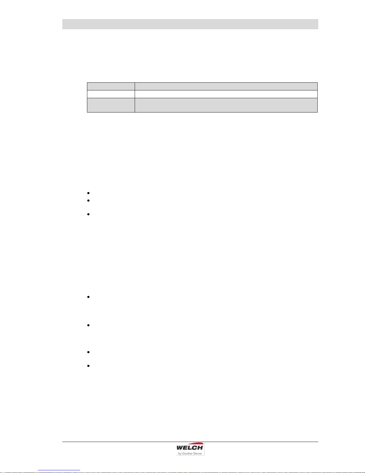
The Laboratory Vacuum Systems are supplied as a ready-mounted unit.
The chemical-resistant diaphragm pump (4) with gas ballast valve (17) is fitted to the base
plate of the column (3) and attached on the suction-side to the separator (7) to protect the
pump from foreign matter and on the pressure-side to the emission condenser (6) to recover
the condensate. This ensures that hazardous substances are separated out. The safety
valve on the emission condenser protects against an impermissibly high operating pressure
on the outgoing air end.
The complete vacuum controller, with sensor, venting valve and power unit (5), is fitted in the
column (3). The LVS 310 Z ef, order no. 115244-04, is an exception. In this case, the vacuum controller is available as an external device for installation in laboratory furniture, see
chapter 3.1.4. The manually regulated LVS-variant does not have a controller.
All exposed glass components (6, 7) are coated with transparent plastic as protection
against bursting. The emission condenser is supplied with insulation.
The power switch (12) and the plug for the power cable (11) as well as the membrane pump
(10), the PC (13) control lead (14), inert gas (16) and the water valve (option) (15) are located on the right of the column.
The LVS types are specially preconfigured according to model.
1
Suction side connection
hose nozzle for hose DN8
Fig. 1a LVS 310 Z - Front view
2
Control valve
(LVS - automatically regulated)
3
Column complete
on swivelling foot
4
Diaphragm pump MPC 301 Z
5
Vacuum controller 521
(in the column or extern)
6
Emission condenser KD 500/5 insulated
at the pressure side with safety valve
and cooling water connections
7
Separator
(round-bottomed flask) suction side
8
Cooling water (feed flow/back flow)
Fig. 1b LVS 310 Z - Rear view
9
Connection outgoing air
hose nozzle for hose DN8
10
Connection Pump (pump)
11
Connection non-heating device power
cable (main in)
12
Main switch (power)
13
Connection PC (RS 232)
14
Connection control cable
LVS - automatically regulated (sensor)
15
Connection water valve
16
Connection inert gas
17
Gas ballast valve

Description
115041 11
3.1.2 Diaphragm pump
► Design:
The diaphragm pump consists of a pump body and a drive motor. The pump body consists
of a drive shaft and two pump heads. Both pump head contains a diaphragm and the work
valves. The two pump heads are arranged opposite each other.
In the two-stage (Z) diaphragm pump, both pump heads are connected in series.
The pump heads are driven via an eccentric shaft with a connecting rod.
► Function:
Motor, eccentric shaft and connecting rod set the diaphragms in stroke movement. This
changes the size of the space between the diaphragms and pump head (pump chamber).
Increasing the size of the pump chamber opens the inlet valve while the outlet valve is
closed (intake process). Decreasing the size of the pump chamber ejects the gas through
the outlet valve.
The valves are actuated by the gas being pumped. A large proportion of fluid in the diaphragm pump minimizes the pumping efficiency.
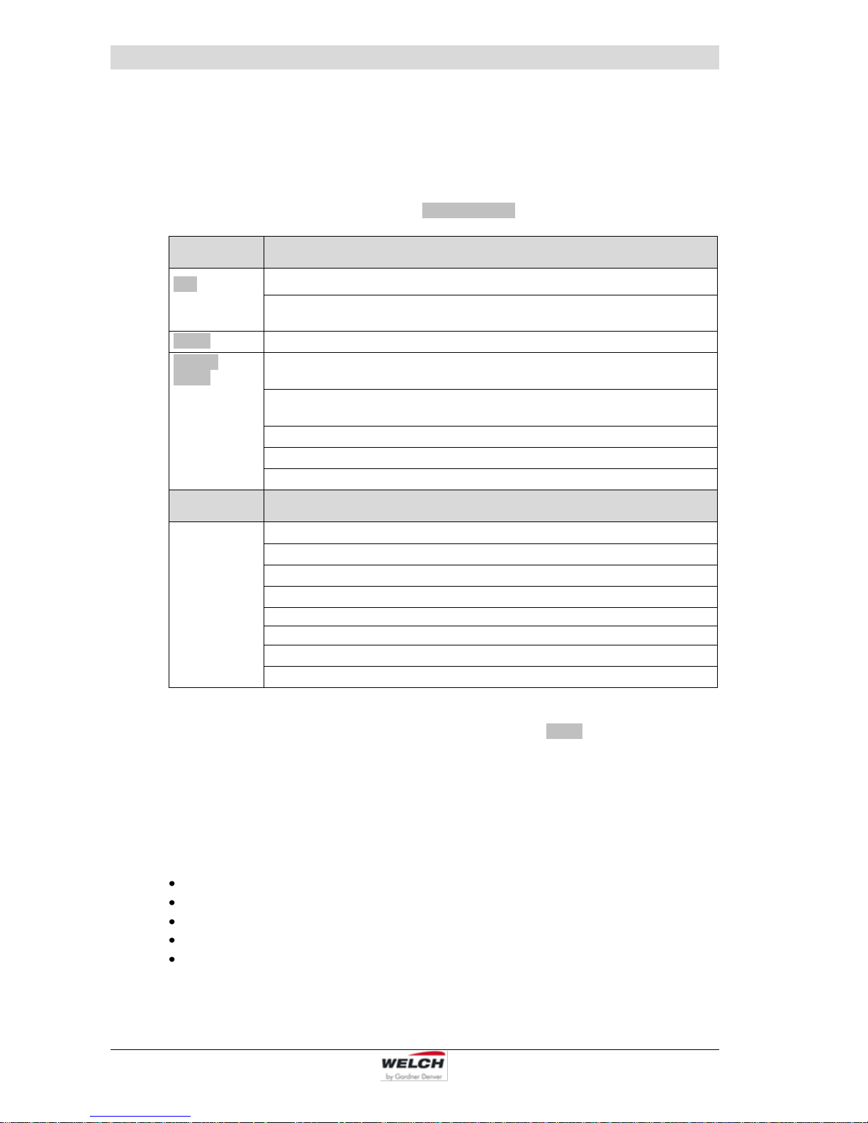
► Materials of the medium-affecting pump parts:
Component
Materials
Seal
EPDM
Screw fitting / Connecting elements
PP, PVDF
Valve
PEEK
Diaphragm
Elastomer + PTFE layer
Vacuum hose
PTFE
Connection head / pump head
PTFE with carbon-fibre reinforcing
*)
*)
electrically conductive (with manufacturer's certificate of electrical conductivity)
Material resistance to aggressive media see: Publisher Hoppenstedt Publishing
(18. September 2007)
► Gas ballast:
When condensable vapours are pumped,
they may be compressed above the
saturated vapour pressure and condense.
Opening the gas ballast valve (17) in the
suction line of the last pump stage allows
air to flow into the pump chamber.
This prevents condensation and flushes
the pump clear.
Operation leads to increasing the ultimate
pressure and the operating temperature.
Fig. 2 Diaphragm pump MPC 301 Z
Description
12 115041
3.1.3 Vacuum Controller 521, intern
In the case of controlled models for laboratory vacuum systems LVS, the vacuum controller,
complete with sensor, venting valve and power unit, is fitted in the device column. The operating and display elements are on the top surface of the column.
(Description and operation see chapter 6, Technical data see chapter 4.3.1)
3.1.4 Built-in – Vacuum Controller 521 ef, extern
The LVS 310 Z ef (Order no. 115244-04) is equipped with an external vacuum controller for
installation in, for example, laboratory furniture.
Over the cable to the device, the electrical connection is made.
1
Built-in –
Vacuum Controller
extern
2
LaboratoryVacuum-System
LVS
► Electrical Installation - Built-in – Vacuum Controller 521 ef extern:
K1 Sensor + Venting valve
on the pump - rear panel
Controller
Coupling plug 5 pole
Order no. 600052-06
K2 24 V DC + Water valve
on the pump - rear panel
Controller
Coupling plug 4 pole
Order no. 600052-06
K3 Frequency converter
on the frequency converter - motor
Controller
Coupling plug 4 pole
Order no. 600052-06
K4 Fill level sensor o p t i o n
on sensor fill level
Controller
Order no. 600052-06
4 m
4 m
4 m
4 m
2
1

Description
115041 13
It has the same function as the LVS with a standard assembly. It is operated, as similarly described, via an externally installed controller. On the controller is the on / off power switch
and the RS 232 interface. (see also chapter 9.4)
Dimensions for installation
in laboratory furniture:
3.2 Overview of the variants
Part
Laboratory-Vacuum-Systems LVS
Piece per LVS
300 Z
301 Z
302 Z
310 Z
311 Z
310 Z ef
310 Z en
Suction side
connections for hose DN 8
1
un-
regulated
1
manually
regulated
2
manually
regulated
1
automati-
cally regu-
lated
1 automatically +
1 manually
regulated
1
ecoflex
regulated
1
economic
regulated
Control valve
- - - 1 1 - -
Column complete
1 1 1 1 1 1 1
Diaphragm pump
1 1 1 1 1 1 1
Vacuum controller 521
- - -
1 (cv)
1 (cv)
1 (ef)
1 (en)
Emission condenser
- 1 1 1 1 1 1
Separator 2 1 1 1 1 1
1
Pressure side
connection for hose DN 8
1 1 1 1 1 1 1
Frequency changer
- - - - - 1 -
Special variants, additional with:
- Dial gauge analog
- 1 - - - - -
- Clamping ring screw
A 10 (netvac 1)
- 1 - 1 - 1 1
- Built-in Controller 521
- - - - - 1 -
3.3 Areas of Application
The Laboratory-Vacuum-Systems is intended for:
vacuum filtration, vacuum distillation and vacuum drying
use in physical and chemical laboratories in trade and industry
pumping and compressing neutral and aggressive gases and vapours
generating a vacuum up to an ultimate pressure of < 8 mbar
► Special designs:
Special LVS can be supplied after consultation with the manufacturer or for a corresponding supply
contract.
Motors for different voltages.
3.4 Scope of Delivery
The scope of delivery is specified in the supply contract.
Description
14 115041
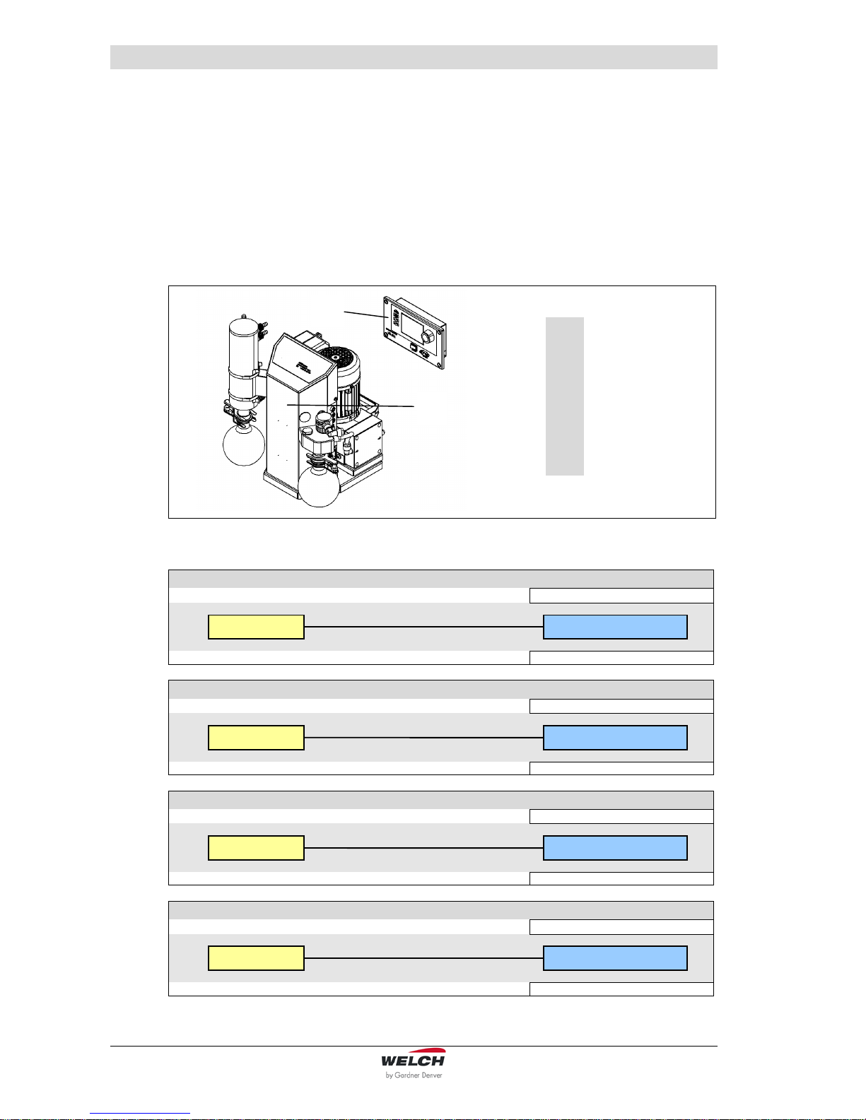
3.5 Examples of application
1
LVS without
vacuum controller
2
Suction line *
3
Outgoing air
4
Rotary vaporizer *
5
Capable of expansion up to 4 loads
6
Coolant system,
un pressurised run
back *
7
Water valve WV *
Fig. 3 Example of application - LVS manually regulated
1
LVS with vacuum
controller and
control valve (cv)
2
Suction line *
3
Outgoing air
4
Rotary vaporizer *
5
Capable of expansion up to 4 loads
6
Coolant system,
un pressurised run
back *
7
Water valve WV *
Fig. 4 Example of application – LVS „cv“ (Control valve) automatically regulated
* Not included in the scope of delivery

Description
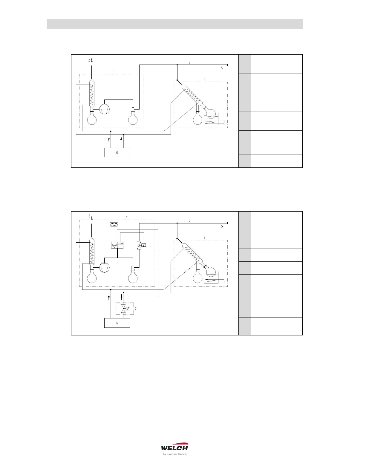
115041 15
1
LVS ef (ecoflex)
2
Suction line *
3
Outgoing air
4
Rotary vaporizer *
5
frequency-regulated
pump motor
6
Coolant system,
un pressurised run
back *
7
Water valve WV *
Fig. 5 Example of application – LVS „ef“ ecoflex
1
LVS en (economic)
2
Suction line *
3
Outgoing air
4
Rotary vaporizer *
5
Capable of expansion up to 4 loads
(depending on the
suction capacity)
6
Coolant system,
un pressurised run
back *
7
Water valve WV *
Fig. 6 Example of application – LVS „en“ economic
CAUTION !
The economic Laboratory Vacuum System "LVS ... en" is suitable for slow
processes and central laboratory supplies using a large hysteresis (< 50 mbar).
When installing the switch interval of the diaphragm pump is to be checked.
In practical applications the time-out must be at least 0.5 minutes.
The integrated pressure monitor guarantees immediate activation of the vacuum
generator when required.
This ensures continuous readiness of the vacuum system in the laboratory.

Description
16 115041
3.6 Accessories
The use of chemical-resistant vacuum connections “netvac +” is recommended for extending the application range of a vacuum generator to several workstations.
netvac +
Set BC1 - 63
Order no. 700563
for mounting
on wood furniture
Set BC2 - 63
Order no. 700563-01
for mounting
on sheet metal wall
with integrated FFKM-Check valve, Dosing valve, Hose nozzle
and Ball valve
Area of application: Laboratory
Suction connection: Hose DN 8-10
Connection thread: 1/4 "- outside
Material of valve body: Polypropylene (PP)
Dimensions (W/D/H): Ø 69 / 161 / 82 mm
Mounting hole: Ø 25 to Ø 35 mm
netvac +
Set BC1 - 62
Order no. 700562
for mounting
on wood furniture
Set BC2 - 62
Order no. 700562-01
for mounting
on sheet metal wall
with integrated FFKM-Check valve, Dosing valve and Hose nozzle
Area of application: Laboratory
Suction connection: Hose DN 8-10
Connection thread: 1/4 "- outside
Material of valve body: Polypropylene (PP)
Dimensions (W/D/H): Ø 69 / 69 / 82 mm
Mounting hole: Ø 25 to Ø 35 mm
Vacuum Control-Box
VCB 521 cv
Order no. 600053
Table model as digital, chemical-resistant vacuum regulator.
With integrated sensor, airing -, control- and check valve.
Connection vacuum apparatus: DN 8
Connection vacuum pump: DN 8
Connection inert gas: DN 4
Connection water valve: Binder plug 4-pole 24V DC
Operating software „WELCH-Control 521“
on CD
Order no. 620637
to connect the vacuum controller to the PC
Description
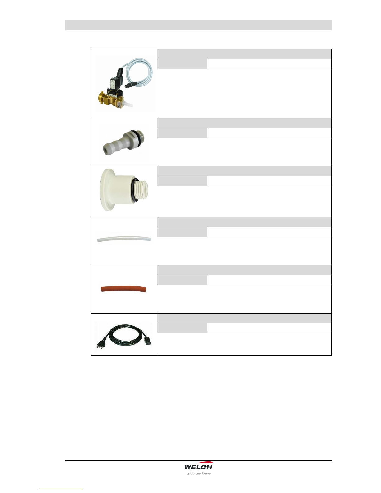
115041 17
Water valve
WV 2
Order no. 700300-02
2 way water flow valve for the demand-responsive cooling water
supply, mounting possible in any direction.
Input: G 3/4 inch sleeve nut
Output: Hose nozzle for hose inside diameters 8 mm
Hose nozzle with FKM - O-Ring
DN 10
Order no. 710955
Material: PP
Male thread: ¼“
Inlet fitting
DN 16 KF
Order no. 710116
Material: PP
Male thread: ¼“
Vacuum hose
10 / 8x1
Order no. 828332
Material: PTFE
Please state the length you want to order!
Vacuum hose
18 / 8x5
Order no. 828310-4
Material: Rubber, red
Please state the length you want to order!
Mains connection cable IEC with plug
Type 12 (CH)
Order no. 825877
for LVS … in 23O V

Technical Data
18 115041
4 Technical Data
4.1 View of device and dimensions
The main dimensions are identical for all types stated here.
Fig. 7 View of device (Model LVS 301 Z, dimensions see chapter 4.3
4.2 Intake Pressure / Pumping Speed – Diagram
Fig. 8 Intake Pressure / Pumping Speed – Diagram
(W)
(H)
(D)

Technical Data
115041 19
4.3 Device data
4.3.1 Laboratory Vacuum Systems
Parameter
Unit
LVS
300 Z
301 Z
302 Z
310 Z
311 Z
Pumping speed 50/60 Hz
DIN 28432
at speed of 1500 rpm
m3 / h
2.3 / 2.5
Ultimate pressure
at speed of 1500 rpm
mbar
8
Ultimate pressure
with gas ballast
at speed of 1500 rpm
18
Max. inlet pressure
bar
1
Max. outlet pressure
1
Intake and pressure ports
-
Hose nozzle DN 8
for hose inside diameter 8 mm
Ambient temperature
°C
+ 10 to + 40
Max. Operating
gas temperature
+ 60
Bearing
-
maintenance-free
Reference surface
sound pressure level
DIN EN ISO 2151
dB (A)
44
Voltage / Frequency
(different data upon
customer request)
V, Hz
230, 50/60 (115, 50/60)
(generally with motor protection switch, switch and cable)
Motor power
W
180
Operating mode
-
S 1
Motor / Type of protection
DIN EN 60529
IP 54
Motor / Class of insulation
DIN EN 600034-1
F (160°C)
Type Examination
Certificate no.
WELCH_ATEX_03-01
Designation EX
II3G IIC T3 X (internal Atm. only)
Dimensions (W/D/H)
mm
360 / 310
/ 395
360 / 310 / 445
Weight
kg
16.1
16.3
16.9
17.8
18.1
Order numbers for :
-
in 230 V
inclusive mains connection cable
IEC with plug CEE, UK
- LVS …
- LVS … with dial gauge analog
- LVS … netvac 1
115041
-
-
115047
115047-10
115047-02
115043
-
-
115044
-
-
115045
-
-
in 115 V
inclusive mains connection cable
IEC with plug US
- LVS …
- LVS … with dial gauge analog
- LVS … netvac 1
115041-01
-
-
115047-01
115047-11
115047-03
115043-01
-
-
115044-01
-
-
115045-01
-
-
in 100 V
inclusive mains connection cable
IEC with plug J
- LVS …
- LVS … with dial gauge analog
115041-05
-
115047-05
115047-12
115043-05
-
115044-05
-
115045-05
-

Technical Data
20 115041
Parameter
Unit
LVS 310 Z ef
LVS 310 Z en
Pumping speed 50/60 Hz
DIN 28432
at speed of 1500 rpm
m3 / h
2.6
2.3 / 2.5
Ultimate pressure
at speed of 1500 rpm
mbar
8
Ultimate pressure
with gas ballast
at speed of 1500 rpm
18
Max. inlet pressure
bar
1
Max. outlet pressure
1
Intake and pressure ports
-
Hose nozzle DN 8
for hose inside diameter 8 mm
Ambient temperature
°C
+ 10 to + 40
Max. Operating gas temperature
+ 60
Bearing
-
maintenance-free
Reference surface sound
pressure level
DIN EN ISO 2151
dB (A)
44
Voltage / Frequency
(different data upon customer request)
V, Hz
230, 50/60 (115, 50/60)
(generally with motor protection switch, switch and cable)
Motor power
W
180
Input Frequency changer
(Apparent power)
W / A
680 / 4.5
-
Operating mode
-
S 1
Type of protection (motor)
DIN EN 60529
IP 54
Motor / Class of insulation
DIN EN 600034-1
F (160°C)
Type Examination Certificate
no.
WELCH_ATEX_03-01
Designation EX
II3G IIC T3 X (internal Atm. only)
Dimensions (W/D/H)
mm
360 / 310 / 445
Weight
kg
19.9
17.8
Order numbers for LVS:
-
in 230 V
inclusive mains connection cable
IEC with plug CEE, UK
- LVS …
- LVS … netvac 1
- LVS … with built-in controller
VC 521 extern
115244
115244-03
115244-04
115248
-
in 115 V
inclusive mains connection cable
IEC with plug US
- LVS …
115244-01
115248-01

Technical Data
115041 21
4.3.2 Vacuum Controller 521
Parameter
LVS 310 Z
LVS 311 Z
LVS 310 Z ef
LVS 310 Z en
Unit
Sensor
integrated
Sensor type
ceramic sensor
-
Measuring range
1 - 1100
mbar
Measuring uncertainty
< ± 0.3 % FS
Controller
Sensor interface :
3 conductor interface
-
- Scan frequency
10
Hz
- Resolution ADC
12
Bit
- Power supply
+ 5 stabilized
V
- Sensor signal
0.5 to 4.5 (optionally also 4..20 mA per jumper possible)
Pressure indicator
digital and graphic
-
Switching accuracy / control
accuracy
±1
digit
Switching outputs :
digital
-
- Voltage level
0; 24
V
- Control power, single
2 x 6
W
- Control power, total
24
Switching outputs used :
3 2 3
-
- Control valve
x - -
- Ventilation valve
x x x
- Water valve x x
x
- Pump net connection
- - x
Frequency converter output :
-
analog
-
- Voltage level
-
0 to 10
-
V
- Resolution DAC
- 8 -
Bit
Communication interface
RS 232
-
Power consumption -
controller in normal operation
max. 15 (depends upon the control power)
W
Fuse (internal controller)
5
A
Power pack
integrated
Operating voltage
90 .. 260
V AC
Operating frequency
50 / 60
Hz
Output voltage
24
V DC
Output current
1.25
A
Output power
100
W
Entire unit
Protective system
IP 20
-
Working temperature
15 - 40
°C
Connections
IN/OUT: RS 232
SUB-D plug 9-pole
-
OUT: Control line for
frequency changer
-
Binder socket 4-
pole
0 - 10 V DC
-
OUT: Control valve
Control valve
integrated
-
-
OUT: Water valve
Binder socket 4-pole, 24 V DC
Connection: Inert gas
integrated, hose nozzle DN 4
The information presented in this material is based on technical data and test results of nominal units. It is believed
to be accurate and reliable and is offered as and aid to help in the selection of products.
It is the responsibility of the user to determine the suitability of the product for the intended use and the user assumes all risk and liability whatsoever in connection therewith. Gardner Denver Thomas GmbH does not warrant,
guarantee or assume any obligation or liability in connection with this information.

Assembly and Installation
22 115041
5 Assembly and Installation
5.1 Unpacking
Carefully unpack the Laboratory-Vacuum-System.
Check the system for:
Transport damage,
Conformity with the specifications of the supply contract (type, electrical supply data),
Completeness of the delivery.
Please inform us without delay if there are discrepancies between the delivery and the contractually agreed scope of delivery, or if damage is detected.
Please take note of the general terms of business of the manufacturing firm.
In case of a claim under warranty, the device must be returned in packaging that is
suitable for protecting it during transport.
5.2 Installation and Connection
Set the Laboratory-Vacuum-System on a flat and horizontal surface.
Remove the protective caps on the connections.
Connect the intake connector of the LVS to your apparatus with vacuum hose DN 8.
Connect the cooling water tube to the emission condenser.
The cooling water return flow must be unpressurized.
Connect the air exhaust to the central air exhaust system.
Connect the Laboratory-Vacuum-System to the power supply.
Check that the connections are properly seated.
5.3 General instructions
Observe the basic safety instructions when using the LVS.
The pressure device regulation 2014/68/EU must be observed if devices with an overpressure of 0.5 bar or more are connected.
The pressures at the intake and exhaust sides of the diaphragm pump at the time it is
switched on must correspond to the specifications of DIN 28432.
In order to avoid pumping speed losses, all the vacuum connecting hoses used should have
a large nominal diameter and should be laid out so that the lengths are as short as possible.
Avoid rigid connections. They must be assembled carefully in order to achieve a low leak
rate.
We recommend fitting non-return valves (order no. 720327) for applications with several
consumers.
The upstream separator on the intake-side serves to protect the diaphragm pump and the
vacuum sensor from condensates and mechanical contamination. It must be used for an application. The level in the separator must be monitored and the separator emptied regularly.
The currently valid regulations must be observed when disposing of waste. The separator on
the intake-side can only be removed and emptied after the system has been vented.

Assembly and Installation
115041 23
The emission condenser enables a 100 per cent recovery of the solvents led through the
vacuum pump. Cooling takes place via the DN 8 hose nozzles. Ensure that the outflow is
clear. The safety valve is located at the gas inlet. The rubber valve seal must be checked
for cracks at regular intervals and exchanged when necessary. The exhaust connection is
unpressurized. It can be led off through a DN 10 hose into a suitable evacuation duct. There
is common solvent reclamation for all the connected systems. Mixing media must not lead to
a hazard for persons, the environment of for the equipment.
Condensable vapours may only be extracted when the pump is at operating temperature.
When doing so, the gas ballast valve should be opened and/or a quantity of air, which is to
be calculated by the user, allowed to enter via the intake port valve. The pressure values
may be increased when doing so. The diaphragm pump's maximum tolerance of water vapour pressure can be improved or a cleaning run can be made after finishing work by opening the gas ballast valve (this significantly reduces the pumping speed and ultimate pressure). The vacuum ducts must always be laid sloping downwards so that condensates can
flow into the relevant separators.
In case of soiling by solid matter, the pump heads must be opened and the entire interior
space, including valves and diaphragm, cleaned mechanically (see chapter 7.2.1).
5.4 Storage
The pumps are to be stored in a low-dust, interior room within the temperature range from
+ 5 to + 40 °C and at a relative air humidity < 90%.
Leave the protective elements on the intake and exhaust ports. Another equally good protection may be used.
5.5 Scrap Disposal
CAUTION !
The Laboratory-Vacuum-Systems must be disposed of in accordance with the
2012/19/EU guideline and the specific national regulations.
Contaminated pump systems must be decon taminated according to the laws.

Operation
24 115041
6 Operation
6.1 LVS without vacuum controller
Switch the device (LVS 300 Z, LVS 301 Z, LVS 302 Z) on using the main switch. Vacuum is
generated immediately and without regulation. Over the regulating valves on the LVS 302 Z
it is possible two customers concomitant to connect.
6.2 LVS with vacuum controller
The LVS is switched on by the rocker switch POWER located on the device.
The device is ready for operation after a short initializing routine, during which a signal tone
sounds and all light elements light up briefly.
In the version LVS with external controller (Order no. 115244-04) is the on / off power
switch on the controller.
6.3 Operating modes of the Controller
The following modes are available:
0 -
STOP
Controller is inactive and can be configured
1 -
Manual operation
With specification of the setpoint and, if required, lowering
2 -
Automatic operation
The setpoint is detected automatically from the pressure development
3 -
Ultimate pressure
Pumping out at maximum motor output
4 -
Self cleaning
Motor runs for 2 minutes at open ventilation valve
6.3.1 Mode 1, Manual operation
The vacuum valve is closed when the pressure reaches the setpoint. Closed-loop control between the set hysteresis and the setpoint has been started.
For operation with a frequency converter, an analog voltage is output, which controls the
speed according to the standard tolerance. If the set pressure is not reached, the speed is
automatically adjusted to the pressure loss.
If the pressure is actively lowered, after the setpoint has been reached for the first time, it is
lowered still further within a settable timeframe. The number of ramps can be set up to a
maximum of 3. Each ramp starts with a holding time. The setpoint then falls in one step to
the defined starting pressure. The setpoint then falls to the final value over the set time.
After the last ramp, there is a waiting time until the automatic STOP
(0 – the last set pressure is held indefinitely until STOP is pressed manually).
CAUTION !
When setting the ramps make sure that the set value is greater than or equal to the
starting value of the first ramp.
The closed-loop control and hysteresis are always related to the current (reduced) setpoint.
The changed setpoint always applies until the STOP button is pressed, then the configuration value applies once more. When the pressure reduction has finished, the control is
stopped, and the system waits until the STOP button is pressed.
6.3.2 Mode 2, Automatic operation
After selection of the operating mode, the controller starts the evacuation. The pressure drop
per minute is determined during this process. If increases during distillation by incipient boiling of the pressure, then this pressure value is taken as the setpoint and proceeds in the
normal control operation.

Operation
115041 25
6.3.3 Mode 3, Ultimate pressure
By pressing of the key P min evacuation takes place at maximum pump speed until the user
presses STOP.
6.3.4 Mode 4, Self cleaning
The Mode "Self cleaning" is used for flushing the pump and can, if desired, also be carried
out several times in succession. After a waiting period of 5 seconds, the evacuation for 2
minutes (at maximum pump power and open vent valve) is carried out. A aborting the process at any time by pressing the encoder (4) possible.
Self cleaning for Controller-version „cv“: The control valve (cv) remains closed when the
mode Manual or Automatic the "ventilation at STOP" parameter = "0".
6.4 Monitoring by Level Sensor
If the level sensor input is activated (optional), the device goes into STOP status when "Tank
full" is signalled.
6.5 Calibrating the Pressure Sensor
A two-point calibration is made with a comparison measurement device.
Calibration at ambient pressure:
Calibration at ultimate pressure:
- The diaphragm pump is switched off.
- The diaphragm pump is switched on.
- The venting valve is open.
- The venting valve will be closed.
- The vacuum valve is closed.
- The vacuum valve will be open.
- The ambient pressure to set.
- The ultimate pressure to set.
CAUTION !
Instead of measuring the pressure with a comparison measurement device, the ultimate pressure of the pump used may also be input if this is known with sufficient
accuracy (take note of evacuation time).
Ensure that the set pressure is also present at the sensor.
6.6 Handling
6.6.1 Control panel
1
START - STOP
4
2
AIR - ventilation
3
P min - pressure drop
5
Encoder (turn / press)
with marking point on encoder
Display
Fig. 9 Control panel
Operation
26 115041
6.6.2 Operating via Buttons and Encoder
The menu is operated with the encoder.
The menu option is selected by turning the encoder anticlockwise, and then confirmed by
pressing.
A pop-up window is provided for changing numerical values. They are accepted by pressing
the encoder.
The process can be cancelled by pressing START - STOP.
Key:
Meaning
AIR
- Switches the venting valve on if the control is inactive.
- Opens the venting valve as long as the button remains pressed while
control is active.
P min
- Starts "ultimate pressure" mode directly.
START
STOP
- Starts the operating mode currently selected in the main menu and the
corresponding set value.
- Starts the operating mode manually with the currently selected setpoint
in the solvent table, see chapter 6.9.
- Stops the active mode
- Cancels the input in the pop-up window.
- Jumps back to the main menu from submenus.
Encoder:
Meaning
- Turn to select the operating mode.
- Press to select the setting menu for the corresponding operating mode.
- Turn to select menu items.
- Press to open Change pop-up window.
- Turn to change values.
- Press to confirm the changed value.
- When active: Turn to change setpoint.
- When active: Press to accept current value as setpoint.
After the current operating mode has been stopped by pressing STOP, the vacuum valve is
closed.
The venting valve takes the selected status (Option: AIR_ON_STOP).
The originally selected values are retained on start.
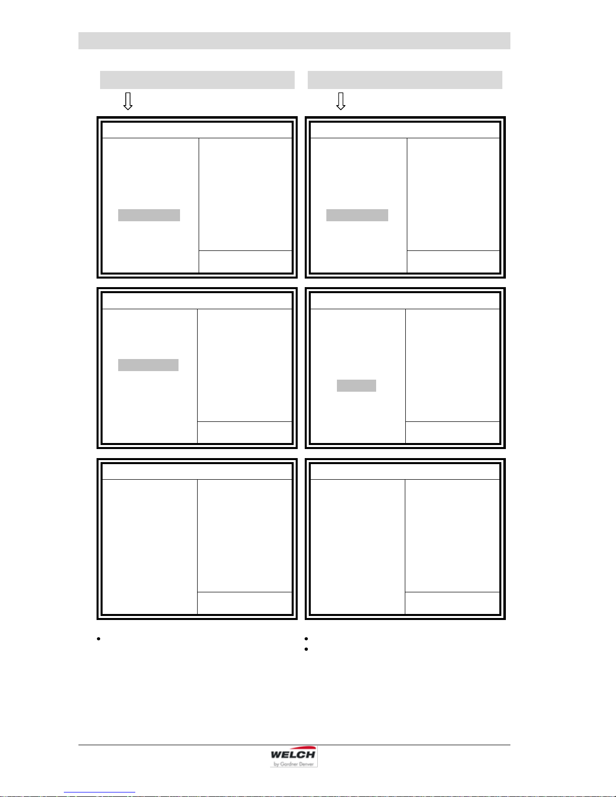
6.6.3 Menu Guidance
After the start, the main menu appears with its 5 submenus, which are shown below:
Manual
Automatic
Low pressure
Configuration
Self cleaning

Operation
115041 27
Configuration: language
Configuration: display settings
MAIN-MENU
Manual
Automatic
Low pressure
Configuration
Self cleaning
VCZ 521
V 1.15
P = 960 mbar
Configuration
language
display settings
pressure unit
calibrate
back
VCZ 521
V 1.15
P = 960 mbar
language
English
Deutsch
Français
Español
back
VCZ 521
V 1.15
P = 960 mbar
MAIN-MENU
Manual
Automatic
Low pressure
Configuration
Self cleaning
VCZ 521
V 1.15
P = 960 mbar
Configuration
language
display settings
pressure unit
calibrate
back
VCZ 521
V 1.15
P = 960 mbar
display settings
contrast
brightness
display interval
min. pressure
max. pressure
back
VCZ 521
V 1.15
P = 960 mbar
Select one of the available languages
Select contrast in the display
Select brightness in the display
Graphic display:
– Number of measurements per second
– Display of min. pressure
– Display of max. pressure
Operation
28 115041
Configuration: pressure unit
Configuration: calibrate
MAIN-MENU
Manual
Automatic
Low pressure
Configuration
Self cleaning
VCZ 521
V 1.15
P = 960 mbar
Configuration
language
display settings
pressure unit
calibrate
back
VCZ 521
V 1.15
P = 960 mbar
pressure unit
mbar
torr
psi
hPa
back
VCZ 521
V 1.15
P = 960 mbar
MAIN-MENU
Manual
Automatic
Low pressure
Configuration
Self cleaning
VCZ 521
V 1.15
P = 960 mbar
Configuration
language
display settings
pressure unit
calibrate
back
VCZ 521
V 1.15
P = 960 mbar
calibrate
Cal. Start pressure
Cal. Low pressure
back
VCZ 521
V 1.15
P = 960 mbar
Select measured values for display
Selection of the upper pressure value
Calibration of the lower pressure value
The current value of the comparison measurement
device must always be entered for calibration. The
correction values are then calculated from this. It is
recommended to always make both calibrations.

Operation
115041 29
Self cleaning:
Low pressure:
MAIN MENU
Manual
Automatic
Low pressure
Configuration
Self cleaning
VCZ 521
V 1.15
P = 960 mbar
MAIN MENU
Manual
Automatic
Low pressure
Configuration
Self cleaning
VCZ 521
V 1.14
P = 960 mbar
MAIN MENU
Manual
Automatic
Low pressure
Configuration
Self cleaning
VCZ 521
V 1.14
P = 960 mbar
MAIN MENU
Manual
Automatic
Low pressure
Configuration
Self cleaning
VCZ 521
V 1.15
P = 960 mbar
Selection self-cleaning -
for flushing the pump (Process several
times in succession possible)
Starting the pump system
All control settings are ignored (P min).
Self cleaning
Attention: system is aired
Start in seconds
5
Cancel with <OK>
Self cleaning
Cleaning in action
Remaining seconds
120
Cancel with <OK>

Operation
30 115041
Automatic:
Manual:
MAIN-MENU
Manual
Automatic
Low pressure
Configuration
Self cleaning
VC 521
V 1.15
P = 960 mbar
Parameter for mode: Automatic
Parameter
Value
Unit
start graphic
start numeric
auto limit
auto speed
hysteresis
auto stop time
No. of pressure ramps
VENTILATE on STOP
Auto Restart
back
-----
----100
50
0
0
0
0
0
-----
%
mbar
sec
Parameter for mode: Automatic
Parameter
Value
Unit
start graphic
start numeric
auto limit
auto speed
hysteresis
auto stop time
No. of pressure ramps
start cycle 1
cycle time 1
cycle pressure 1
VENTILATE on STOP
Auto Restart
back
-----
----100
50
0
0
1
2
600
600
0
0
-----
%
mbar
sec
mbar
sec
mbar
MAIN-MENU
Manual
Automatic
Low pressure
Configuration
Self cleaning
VC 521
V 1.15
P = 960 mbar
Parameter for mode: Manual
Parameter
Value
Unit
start graphic
start numeric
Setpoint numeric
setpoint table
hysteresis
auto stop time
No. of pressure ramps
VENTILATE on STOP
Auto Restart
back
-----
----123
123
0
0
0
0
0
-----
mbar
mbar
mbar
sec
Parameter for mode: Manual
Parameter
Value
Unit
start graphic
start numeric
Setpoint numeric
setpoint table
hysteresis
auto stop time
No. of pressure ramps
start cycle 1
cycle time 1
cycle pressure 1
VENTILATE on STOP
Auto Restart
back
-----
----123
123
0
0
1
2
600
600
0
0
-----
mbar
mbar
mbar
sec
mbar
sec
mbar
Select and set the displayed values.
Values that are not required are not displayed.
Parameter display: "Hysteresis" only when
operating without a FU-Motor (Factory settings!)
Select and set the displayed values.
Values that are not required are not displayed.
Parameter display: "Hysteresis" only when
operating without a FU-Motor (Factory settings!)

Operation
115041 31
6.7 Electrical parameters
6.7.1 Printed circuit board – Layout and Connections
Fig. 10 Positions of components and interfaces
6.7.1.1 Electrical Interfaces
Location of interfaces, see Figure 6
The device is supplied with 24 V DC.
X1 Power supply input
Spring contact clamp Wago type 236 / 2-pole
Pin no.
Function
Specification
Comment
1
GND
reverse polarity protected /
blue
2
Primary power supply
24V DC ± 10%, 1.5 A
reverse polarity protected /
orange
X7
X9
X2

Operation
32 115041
X2 LCD Display BP320240E / INTERNAL
FFC Würth 686124144 24-pole / RM 1mm
Pin no.
Function
Specification
Comment
1
RESET
2
/RD
3
/WR
4
/CS
5
A0
6
D0 7 D1 8 D2 9 D3
10
D4
11
D5
12
D6
13
D7
14
VDD
15
VSS
16
VLCD
17
free
18
SK/X1
19
D0/X2
20
D1/Y1
21
CS/Y2
22
INT
23
LED+
24
LED-
X3 PLC input 1- Level sensor
Spring contact clamp Wago type 236 / 3-pole
Pin no.
Function
Specification
Comment
1
GND
bl
2
SENSOR 1 or PCL input 1
I in approx. 10 mA /
U
threshold
approx. 13 V
gn
3
Sensor supply
Corresponds to the voltage at
X1 / protected by 200 mA
self-resetting circuit-breaker
orange
X4 Pressure sensor 1 input
Spring contact clamp Wago type 236 / 4-pole
Pin no.
Function
Specification
Comment
1
GND
blue
2
SENSOR 1 Signal
0..5 V or 0..20 mA
Resolution 5 mV / green
3
Sensor supply
5 V ± 5% or
Corresponds to the voltage at
X1 / protected by 200 mA
self-resetting circuit-breaker
Not fused / beige

Operation
115041 33
The input can be configured with jumper J2:
J2 open: (Default) Voltage: 0..5 V
J2 plugged: current 0..20 mA
The sensor supply voltage can be configured with jumper J3:
J3 1-2: 24 V needed for current output
J3 2-3: 5 V (Default) needed for voltage output (depending on sensor data sheet)
X5 PLC output 1 – vacuum valve
X6 PLC output 2 – venting valve
Spring contact clamp Wago type 236 / 2-pole
Pin no.
Function
Specification
Comment
1
GND output
bl
2
Output
Corresponds to the voltage
infeed at X1 / pnp max. 0.5 A
with freewheeling diode /
orange
X7 RS232 to the PC
Tub plug connector, 10 pin via FB to
Sub-D-plug, 9-pin (Würth 618009221823)
Function
Pin at tub plug connector
Pin at SUB - D
Comment
RXD 3 2
TXD 5 3
GND 9 5
X8 Analog output 1 – Frequency converter pump speed
Spring contact clamp Wago type 236 / 2-pole
Pin no.
Function
Specification
Comment
1
GND
bl
2
Output 1
0..10 V max. 10 mA
Resolution 2 mV / gr
X9 DEBUG / INTERNAL
Tub plug connector, 10 pin / RM 2.5mm
Pin no.
Function
Specification
Comment
1 2 3 4 5
Level converter supply
5 V ± 5%
not fused 6 7
8
TXD
5 V level
9
RXD
5 V level
10
GND
Operation
34 115041
6.7.2 Software-Update
The software in the controller can be updated.
It can be re-input by the user. The Fujitsu Flash tool must be used for the Fujitsu 16FX CPU
range.
The factory default settings can be made with a corresponding sequential number input again (VCZ521_XXX.mhx).
NOTE !
The highest sequential number VCZ521_XXX.mhx is always the most current software version. (currently: VCZ521_115.mhx)
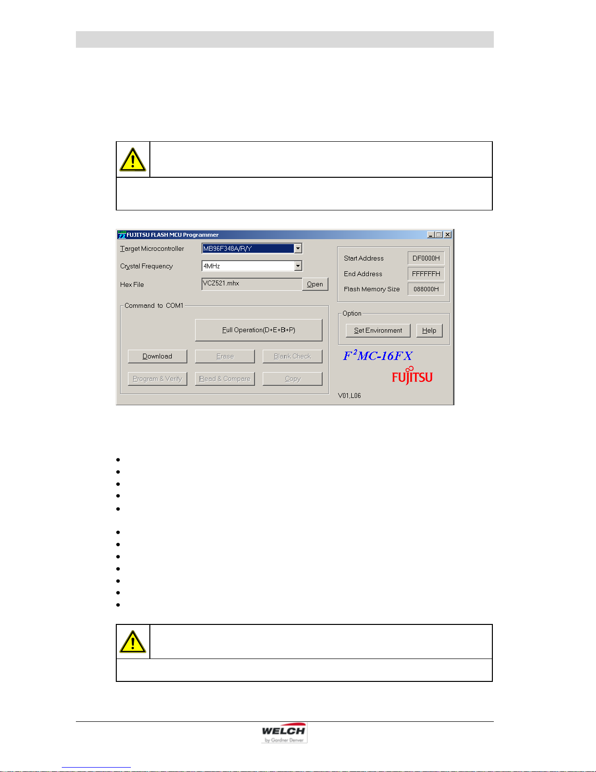
The following steps must be carried out:
Switch off the controller
Call the flash program.
Select the processor MB96F348A/R/Y
Select the quartz frequency 4 MHz
Select the program file
(Most Current Version = Highest Sequential Number, VCZ521_XXX.mhx)
Select the serial interface used (Option / Set Environment)
Start the programming with "Full Operation"
Confirm the Box (PC) „Reset ...“ with OK
Switch on the controller quickly (don't forget timeout of approx. 15 seconds!)
The programming runs automatically.
Switch off the controller again after the OK message
Switch on the controller, and check the functions of the controller
CAUTION !
The controller should be switched off during each interruption.

Operation
115041 35
6.8 Operation using the "WELCH-Control 521" PC program
The "WELCH-Control" enables the vacuum controller to be operated simply and easily from
the PC. The program can be purchased and installed as an option.
Make the cable connection (O-Modem) between PC and controller.
PC program
Most Current Version
Order no.
WELCH-Control 521
V 1.15
620637
CAUTION !
1.) "WELCH-Control 521" is currently version V 1.15.
2.) Flash software is also currently version VCZ521_115.mhx.
3.) Version 1.) and 2.) need not be identical!
The program attempts to find a switched-on controller on COM1 to 20. A COM-Port 1..255
can also be defined as a command line parameter: VCZ521.EXE 2 -> select COM2
If a controller cannot be found, the program goes into offline mode.
Here, a previously saved curve can be reloaded and printed out.
Internal wiring of the controller RS 232 port
PIN
Cable colour
Connection on the main board
2
white
16
RS 232 - RXD
3
brown
17
RS 232 - TXD
5
green
18
GND
9
yellow
19
Flash - sets software update mode if on GND (18)
The following screen appears after the start:
The graph shows the pressure development. Both the chronological and the pressure display range can be set. Data can also be recorded in the PC memory, which can then be
stored as an ASCII file in the "File / Save memory" menu.

Operation
36 115041
In the PSI pressure range, the pressure values for the curve are multiplied by 100 to remain
with integers.
The curve can be printed out by the system printer via the "File / Print curve" menu.
The buttons largely correspond to the buttons on the controller. However, the buttons cannot
be held down.
In active mode, the AIR button can be used with the mouse like on the controller.
Pressing the mouse button opens the valve, releasing it closes the valve again.
However, this only works if the mouse pointer is still on the AIR button.
The Up and Down arrow buttons change the temporary setpoint in active mode.
The OK button only works in active mode, and sets the current pressure as the new set
value.
The Start button starts or ends in the current operating mode.
The Pmin button functions the same as without a controller.
The following menu items can be selected from the menu bar:
File
Measure!
Settings!
Calibrate!
Factory settings!
6.8.1 Menu item: „File“
File
Save settings
Saving the Settings dialog settings in a file
Load settings
Loading the Settings dialog settings from a file
Print settings
Printing out an image of the Settings dialog on the standard printer
Save memory
Saving the pressure data in a file
Load memory
Load the print data from a file
Print curve
Printing out the current pressure curve on the standard printer
Password
Changing the basic setting of the controller is password-protected.
Release is given by inputting the date as a hex number.
Example : 25.03.2015 = 250315 = 3D1CB
(Required for activating the "Calibrate" and "Factory settings" menus and the direct input
of pressure offset und pressure factor in the „Calibrate“ Dialog)
Info
Information about the program version
Exit <ESC>
Exit program

Operation
115041 37
6.8.2 Menu item: „Settings!“
CAUTION !
Settings not required for the selected operating mode are disabled and grayed out in
the display. Appropriate error messages are displayed if the data ranges are exceeded or if inputs are illogical.

Operation
38 115041
Settings required for the control behaviour of the controller:
Designation
Explanation
Software
WELCH-Control
521
Control panel
at the controller
mode
MAIN MENU
1 - manual
(manual pressure setting for boiling pressure)
2 - automatic
(automatic finding of the boiling pressure)
3 - low pressure
Operation without regulation
There are only the modes meaningful for their application adjustable.
language
-
english, german, french, spain
-
Configuration,
language
English, Deutsch, Français, Español
pressure unit
pressure unit
mbar, torr, psi, hPa
VENTILATE
on STOP
-
ON - automatic venting after STOP is on
OFF - automatic venting after STOP is off
-
VENTILATE
on STOP
0 - closed
1 - open
Auto Restart
-
OFF - no function
ON - The program works automatically continues
after power failure or shutdown.
-
Auto Restart
0 - no function
1 - The program works automatically continues
after power failure or shutdown.
manual, setpoint
setpoint
Enter a setpoint pressure value between 0 and 1100
mbar.
manual, hysteresis
hysteresis
Enter a hysteresis value between 0 and 1100 mbar.
pressure drop,
ramp num
No. of pressure
ramps
Number of possible ramps 1, 2 , 3
P start, ramp 1 – 3
start cycle 1 – 3
in adjusted pressure value (example: mbar)
P lower, ramp 1 – 3
cycle time 1 – 3
in second absolute
T lower, ramp 1 – 3
cycle pressure 1 – 3
in adjusted pressure value absolute (example: mbar)
auto stop time
auto stop time
Hunting time in second
auto limit
auto limit
Threshold value for detecting the boiling point
(selected pressure unit / min)
auto speed
auto speed
0 ... 100%
Reduces the frequency of rotation / rotational speed
to a percentage of the maximum speed
of the pump motor in order to determine the
boiling point smoothly.
read config
-
Read out current parameter values from the
controller and display in the Settings dialog.
send config
-
Values changed in the Settings dialog are stored in
the controller. The controller confirms reception with
a signal tone.

Operation
115041 39
6.8.3 Menu item: „Calibrate“
Calibration:
When search lower point (Pmin) is activated, evacuation is to the lower point. If the pressure does not fall any further, the value can be entered by using a comparison measurement
device and confirmed with Ok. The system is vented and the ambient barometric pressure
entered as the upper point (Pmax). Do not confirm until the value has been established.
If the controller is integrated in a complete system or pump system (LVS), evacuation and
venting take place automatically when the stated buttons are pressed.
The calculated correction values are displayed and can be stored with save.
CAUTION !
Ensure that the set pressure is also present at the sensor.
Designation
Explanation
Software
WELCH-Control 521
Control panel
at the controller
Lower point
CL
at low pressure -
pressure of comparison measurement device
(at lowest possible pressure, e.g. 10 mbar)
Upper point
CH
at normal pressure (high) -
barometric pressure

Operation
40 115041
6.8.4 Menu item: „Factory settings“
Designation
Explanation
Software
WELCH-Control 521
Control panel
at the controller
FU motor
not settable
analog output active
calibration allowed
not settable
= present
= not present
read
not settable
Reading the set values
Confirmation of acceptance by signal tone
send
not settable
Transmission of changed values to the controller
Confirmation of acceptance by signal tone
CAUTION !
These settings are adapted by the manufacturer to match the supplied configuration.
The user can change the settings after inputting the password (“File” menu item).

Operation
115041 41
6.9 Table of solvents
Solvent
Formula
Vacuum (mbar)
for boiling point at 40 °C
Acetone
C3H6O
556
n-amyl alcohol, n-pentanol
C5H12O
11
Benzole
C6H6
236
n-butanol
C4H10
25
tert-butyl alcohol, 2-methyl-2-propanol
C4H10O
130
Tetrachlorometane
CCl4
271
Chlorobenzene
C6H5Cl
36
Chloroform
CHCl3
474
Cyclohexane
C6H12
235
Diethyl ether
C4H10O
no vacuum
1, 2, -dichlorethane
C2H4Cl2
210
1, 2, -dichlorethylene (cis)
C2H2Cl2
479
1, 2, -dichlorethylene (trans)
C2H2Cl2
751
Diisopropyl ether
C6H14O
375
Dioxan
C4H8O2
107
DMF
C3H7NO
11
Ethanol
C2H6O
175
Ethyl acetate
C4H8O2
240
Heptane
C7H16
120
Hexane
C6H14
335
Isopropyl alcohol
C3H8O
137
Isoamyl alcohol, 3-methyl-1-butanol
C5H12O
14
Ethyl methyl keton
C4H8O
243
Methanol
CH4O
337
Methylene dichloride, dichloromethane
CH2Cl2
no vacuum
Pentane
C5H12
no vacuum
n-propyl alcohol
C3H8O
67
Pentachlorpethane
C2HCl5
13
1, 1, 2, 2, -tetrachloroethane
C2H2Cl4
35
1, 1, 1, -trichloroethane
C2H3Cl3
300
Tetrachloroethylene
C2Cl4
53
THF
C4H8O
357
Toluol
C7H8
77
Trichloroethylene
C2HCl3
183
Water
H2O
72
Xylol
C8H10
25
Vacuum in Torr/mmHg = X mbar x 0.75

Maintenance and Servicing
42 115041
7 Maintenance and Servicing
7.1 General Requirements
Repairs of the Laboratory-Vacuum-Systems may only be performed by the manufacturer or
authorized workshops.
The prerequisites are a complete and factually correct damage report, and a clean and, if
necessary, a decontaminate device.
The operator may perform maintenance work to the extent indicated below:
7.2 Maintenance Performed by the User
WARNING !
Only perform the work that is described here, and that which is permitted to be done
by the user.
All other maintenance and service work may only be performed by the manufacturer
or a dealer authorized by him.
Beware of the pump parts being possibly contaminated by hazardous substances.
Wear protective clothing if there is contamination.
7.2.1 Maintenance of the diaphragm pump
Check the pump daily for unusual running noises and heat building up on the surface of
the pump.
We recommend changing the diaphragm after 10,000 operating hours. The user may
specify that the exchange be made earlier, depending upon the application process.
Check the electrical and vacuum connections daily.
Scope of permissible work:
Loosen and remove the hoses
Open and remove the pump heads
Inspect the pump chambers, diaphragms and valves
Deposits in the inside of the pump must be cleaned out
Change the diaphragms, valves and seals
Tools required:
Tool kit: Order No. 402106, consists of:
Order no. 826801 Pin type face wrench, adjustable, size 3,
Order no. 826801-6 Allan key, size 4,
Order no. 826801-5 Open spanner, size 17.

Maintenance and Servicing
115041 43
7.2.1.1 Disassembly
1. Disconnect the power supply and ensure that it cannot be switched on again.
2. Open the screw clamps (9) of the hoses (10) on the pump body with the SW 17 open
spanner.
3. Remove four machine screws (1) from each connection head with an Allan key, size 4.
4. Lift off the connection head (2) and the pump head (5). The valves (3), o-rings (4) and
diaphragm (7) are now freely exposed.
5. Loosen the diaphragm (7) at the strain washer (6) by turning the size 3 pin type face
wrench anticlockwise.
6. Clean the valves (3), the pump head (5) and the diaphragm (7) with a soft cloth and acetone.
7. Check that the drive is in good working order.
Fig. 11 Disassembly, assembly
WARNING !
Renew defective parts, if necessary! Wear protective gloves!
Parts must be renewed at the intervals stated in this Operating Manual or as specified by the user internally!
Do not clean with compressed air!
7.2.1.2 Assembly (see fig. 11)
1. Place the pump so that the diaphragm is lying in a horizontal position.
2. Use the size 3 pin-type face wrench to tighten the pressure disc (8), the diaphragm (7)
and the strain washer (6) with the correct torque of 5 - 6 Nm.
3. Bring the connecting rod (see fig. 20) and the diaphragm (7) into the central position.
4. Replace the pump head (5).
5. Insert the valves (3) and the o-rings (4).
Ensure that they are lying completely flat. Do not insert the burred side facing the sealing
surface. Align the connection head flush with the pin.
6. Tighten the four machine screws (1) symmetrically with a torque of 3 - 4 Nm.
7. Reattach the hose (10) connections with clamping ring screw fittings (9).

Maintenance and Servicing
44 115041
7.2.1.3 Test
Connect a vacuum measuring device to the intake connector and measure the ultimate
pressure.
If the device is working properly, then the figure stated in the technical data must be attained within a maximum of one minute.
The pump must not make any abnormal noises.
Moving parts must not touch each other.
7.2.2 Maintenance of the vacuum controller
The vacuum controller is maintenance-free. In case of damage, return the device to the
manufacturer or to an authorized workshop.
7.2.3 Maintenance of other components
Empty the glass drip pan in a timely manner, observe all disposal specifications as applicable to hazardous substances.
Screw connections must be checked for tightness and tightened when necessary.
Check vacuum hoses for leaks and, if necessary, replace them.
Check that the glass vessels are undamaged and if necessary replace.
Check rubber gasket of the safety valve at the emission condenser and, if necessary, re-
place it.
7.3 Maintenance by the Manufacturer
Repairs and maintenance going beyond the extent of the work described in chapter 7.2 or
reconditioning or modification may only be performed by the manufacturer or authorized
workshops.
WARNING !
The user shall be liable for the consequences of an incorrect damage report or a
contaminated pump. The statements in the damage report are legally binding.
7.4 Damage Report
You find the form of the damage report to the Download on our web page in the menu "service" and "Downloads". www.welchvacuum.com
If you should not have an entrance to the Internet, you can request the form also gladly with
us, under phone +49 3677 604 0.
WARNING !
Incomplete or incorrectly completed damage reports may endanger the service personnel!
Provide full information about contamination, and clean the pump thoroughly before
handing it over to third parties.

Troubleshooting
115041 45
8 Troubleshooting
Only manufacturing firm and authorized service workshops may work on the pump systems
and their accessories during the warranty period.
Trouble
Cause
Remedy
by:
with:
Vacuum pump
does not start
No power supply
Qualified
electrician
Check electrical installation
Motor defective
Service
workshop
Exchange
Pump body defective
Repair and/or exchange
Vacuum pump
does not
generate a
vacuum or
only an
inadequate
one
Connected apparatus
and/or connecting
elements leaking
User or
Service
workshop
Identify and seal the leak,
replace the seals and/or
hoses if necessary.
Vacuum pump leaking
Check the hose
connections between the
pump heads, replace the
hoses and/or fittings
if necessary.
Pump head leaking
Service
workshop
Repair and/or exchange
Diaphragm defective
User or
Service
workshop
Exchange of the diaphragm
(see chapter 7.2)
Valve defective
Exchange of the valve
(see chapter 7.2)
Vacuum pump dirty
General maintenance /
leaning
Valves dirty
Cleaning condensates
and foreign objects out of
the valves.
Running noise
Vacuum pump dirty
User or
Service
workshop
General maintenance /
cleaning
Glass
components
defective and/or leaking
User
Exchange of the glass
parts or seals
Cable(s)
defective and/or brittle
Qualified
electrician
Exchange of the cable(s)
No pressure
indicated on
the controller
No power supply
Qualified
electrician
Electrical system to be
checked
Controller
cannot be set
or programmed
Electronics / display
are defective
Service
workshop
Repair and/or exchange
Missing
control signal
Incorrect input
User
Check the input
and correct if necessary
Controller defective
User
Switch the device off,
and switch it on again after
three seconds
User or
Service
workshop
Replace the controller

Spare Parts Overview
46 115041
9 Spare Parts Overview
The spare parts list contains all the spare parts and all the information necessary for ordering.
When ordering, please quote the description, quantity, serial number and order number!
CAUTION !
We are not liable for any damage caused by the installation of any parts not supplied
by the manufacturer.
9.1 Service kit - Diaphragm Pump
Designation
Order no.
Service kit
402041
The service kit consists of:
Designation
Piece
Order no.
O-Ring ø 12 x 2
5
829217-3
O-Ring ø 25 x 2
4
829250-1
Diaphragm 2 400732
Valve 4 400656

Spare Parts Overview
115041 47
9.2 Spare parts – Laboratory-Vacuum-Systems, unregulated + manually regulated
Spare parts view LVS 300 Z, unregulated
Fig. 12 Front- and rear unit - LVS unregulated (without item no. 1 and 2)

Spare Parts Overview
48 115041
Spare parts view LVS 302 Z, manually regulated
Fig. 13 Front- and rear unit - LVS manually regulated (without item no. 1 and 2)

Spare Parts Overview
115041 49
Spare parts list - LVS 300 Z, LVS 302 Z, manually regulated
Item
no.
Designation
Piece
LVS 300 Z
LVS 302 Z
Order no.
115041
115041-01
115041-05
Order no.
115043
115043-01
115043-05
Order no.
Order no.
1
Diaphragm pump MPC 301 Z (230V)
(consisting of: – see chapter 9.6)
1
412722-05
412722-05
- Mains connection cable IEC + plug CEE (D)
1
825885
825885
- Mains connection cable IEC + plug BS (UK)
1
825878
825878
Diaphragm pump MPC 301 Z (115V)
(consisting of: – see chapter 9.6)
1
412722-06
412722-06
- Mains connection cable IEC + plug NEMA
5-15 (US)
1
825903
825903
Diaphragm pump MPC 301 Z (100V)
(consisting of: – see chapter 9.6)
1
412722-08
412722-08
- Mains connection cable IEC + plug JIS (J)
1
825911
825911
2
Straight threaded joint with seal edge
PVDF 10 - 1/4”
2
829931
- 1 -
829931
3
Column 1 complete (consisting of pos. 4 – 12)
1
115502
-
Column 3 complete (consisting of pos. 4 – 12)
1 - 115502-02
4
Rear panel
1
115512-02
115512-02
5
Emission condenser complete KD 500/5
(consisting of pos. 5a – 5k)
1 - 700183-08
5a
- Intensive cooler with isolation
1 - 720480
5b
- Round-bottomed flask 500 ml – KS 35
1 - 828839
5c
- Ball and socket clamp – KS 35
1 - 828845
5d
- Screw cap GL 14
2 - 828872
5e
- Hose nozzle GL 14
2 - 828872-1
5f
- Safety valve
1 - 100838-01
5g
- Vacuum hose PTFE, 10/ 8x1 (sold be the meter)
0.15 m - 828332
5h
- Screw cap GL 18
2 - 828876
5j
- Hose nozzle GL 18
1 - 828876-1
5k
- Silicon sealing GL 18
1 - 828876-2
6
Valve seat complete
1
113528-1
113522
7
Round-bottomed flask 500 ml – KS 35
2
828839
- 1 -
828839
8
Ball and socket clamp – KS 35
2
828845
- 1 -
828845
9
Hose nozzle DN 8 – G ¼“
2
710798-06
-
10
Retaining strap 70 – 75 mm
2 - 824130
11
Rubber metal-pad
6
829138-1
829138-1
12
Fine control valve VVC-M2
2 - 700443-01

Spare Parts Overview
50 115041
Spare parts view LVS 301 Z, manually regulated
Fig. 14 Front- and rear unit – LVS manually regulated (without item no. 1 and 2)

Spare Parts Overview
115041 51
Spare parts list - LVS 301 Z, manually regulated
Item
no.
Designation
Piece
LVS 301 Z
LVS 301 Z
with analog
dial gauge
LVS 301 Z
netvac 1
Order no.
115047
115047-01
115047-05
Order no.
115047-10
115047-11
115047-12
Order no.
115047-02
115047-03
Order no.
Order no.
Order no.
1
Diaphragm pump MPC 301 Z (230V)
(consisting of: – see chapter 9.6)
1
412722-05
412722-05
412722-05
- Mains connection cable IEC + plug CEE (D)
1
825885
825885
825885
- Mains connection cable IEC + plug BS (UK)
1
825878
825878
825878
Diaphragm pump MPC 301 Z (115V)
(consisting of: – see chapter 9.6)
1
412722-06
412722-06
412722-06
- Mains connection cable IEC + plug NEMA
5-15 (US)
1
825903
825903
825903
Diaphragm pump MPC 301 Z (100V)
(consisting of: – see chapter 9.6)
1
412722-08
412722-08
-
- Mains connection cable IEC + plug JIS (J)
1
825911
825911
-
2
Straight threaded joint with seal edge
PVDF 10 – 1/4”
1
829931
829931
829931
O-Ring EPDM 12 x 2
1 - -
829217-3
3
Column 7 complete (consisting of pos. 4 – 15)
1
115502-06
115502-22
-
Column 2 complete (consisting of pos. 4 – 15)
1 - -
115502-13
4
Rear panel
1
115512-02
115512-02
115512-02
5
Emission condenser complete KD 500/5
(consisting of pos. 5a – 5k)
1
700183-08
700183-08
700183-08
5a
- Intensive cooler with isolation
1
720480
720480
720480
5b
- Round-bottomed flask 500 ml – KS 35
1
828839
828839
828839
5c
- Ball and socket clamp – KS 35
1
828845
828845
828845
5d
- Screw cap GL 14
2
828872
828872
828872
5e
- Hose nozzle GL 14
2
828872-1
828872-1
828872-1
5f
- Safety valve
1
100838-01
100838-01
100838-01
5g
- Vacuum hose PTFE, 10/ 8x1
(sold be the meter)
0.15 m
828332
828332
828332
5h
- Screw cap GL 18
2
828876
828876
828876
5j
- Hose nozzle GL 18
1
828876-1
828876-1
828876-1
5k
- Silicon sealing GL 18
1
828876-2
828876-2
828876-2
6
Valve seat complete
1
113522
113522
113528-1
7
Round-bottomed flask 500 ml – KS 35
1
828839
828839
828839
8
Ball and socket clamp – KS 35
1
828845
828845
828845
9
Threaded elbow joint PVDF, 10
1 - -
829983
Hose connector PVDF, A10 - 8
1 - -
829924-1
Setting nipple PVDF, A10 – ¼“
1 - -
829982
10
Retaining strap 70 – 75 mm
2
824130
824130
824130
11
Rubber metal-pad
6
829138-1
829138-1
829138-1
12
Fine control valve VVC -M2
1
700443-01
-
-
13
Fine control valve VVC -M3
with dial gauge analog
1 - 700444-02
-
14
O-Ring EPDM 15 x 2
1
829311-1
829311-1
-
15
O-Ring EPDM 12 x 2
2 - -
829217-3

Spare Parts Overview
52 115041
9.3 Spare parts – Laboratory-Vacuum-Systems, automatically regulated
Spare parts view LVS 310 Z
Fig. 15 Front- and rear unit - LVS automatically regulated (without item no. 1 and 2)

Spare Parts Overview
115041 53
Spare parts view LVS 311 Z
Fig. 16 Front- and rear unit - LVS automatically regulated (without item no. 1 and 2)

Spare Parts Overview
54 115041
Spare parts list – LVS 310 Z, LVS 311 Z, automatically regulated
Item
no.
Designation
Piece
LVS 310 Z
LVS 311 Z
Order no.
115044
115044-01
115044-05
Order no.
115045
115045-01
115045-05
Order no.
Order no.
1
Diaphragm pump MPC 301 Z (230V)
(consisting of: – see chapter 9.6)
1
412722-05
412722-05
- Mains connection cable IEC + plug CEE (D)
1
825885
825885
- Mains connection cable IEC + plug BS (UK)
1
825878
825878
Diaphragm pump MPC 301 Z (115V)
(consisting of: – see chapter 9.6)
1
412722-06
412722-06
- Mains connection cable IEC + plug NEMA
5-15 (US)
1
825903
825903
Diaphragm pump MPC 301 Z (100V)
(consisting of: – see chapter 9.6)
1
412722-08
412722-08
- Mains connection cable IEC + plug JIS (J)
1
825911
825911
2
Straight threaded joint with seal edge
PVDF 10 – 1/4”
1
829931
829931
3
Column 4 complete (consisting of pos. 4 – 18)
1
115502-03
-
Column 5 complete (consisting of pos. 4 – 18)
1 - 115502-04
4
Rear panel 1 complete
(consisting of pos. 4a – 4f)
1
115503-06
115503-06
4a
- Socket for non-heating apparatus
1
825274-7
825274-7
4b
- Device plug combination with system filter
1
825297
825297
4c
- Switch green 2 pole
1
825184
825184
4d
- Sub miniature round plug - flange box 4 pole
2
825277-1
825277-1
4e
- NT-switch power pack 24 V
1
827400-5
827400-5
4f
- Circuit board 521
1
827429
827429
5
Emission condenser complete KD 500/5
(consisting of pos. 5a – 5k)
1
700183-08
700183-08
5a
- Intensive cooler with isolation
1
720480
720480
5b
- Round-bottomed flask 500 ml – KS 35
1
828839
828839
5c
- Ball and socket clamp – KS 35
1
828845
828845
5d
- Screw cap GL 14
2
828872
828872
5e
- Hose nozzle GL 14
2
828872-1
828872-1
5f
- Safety valve
1
100838-01
100838-01
5g
- Vacuum hose PTFE, 10/ 8x1 (sold be the meter)
0.15 m
828332
828332
5h
- Screw cap GL 18
2
828876
828876
5j
- Hose nozzle GL 18
1
828876-1
828876-1
5k
- Silicon sealing GL 18
1
828876-2
828876-2
6
Valve seat complete
1
113522
113522
7
Round-bottomed flask 500 ml – KS 35
1
828839
828839
8
Ball and socket clamp – KS 35
1
828845
828845
9
Sensor – built-in controller
1
620052-17
620052-17
10
Screw in socket amended
1
160537
160537
11
Screw in socket
1
828791
828791
12
Distance piece M5/M5
1
160529
160529
13
Silicone hose I 3 x 1.5 mm
0.2 m
H100086
H100086
14
Retaining strap 70 – 75 mm
2
824130
824130
15
Rubber metal-pad
6
829138-1
829138-1
16
Automatic valve VVC-E4
1
700425-01
-
Automatic valve VVC-E4 + Sensor connection
1 - 700425-02
17
Fine control valve VVC-M2
1 - 700443-01
18
Straight threaded joint with seal edge
PVDF 8 - 1/4”
1
829919-1
829919-1

Spare Parts Overview
115041 55
9.4 Spare parts – Laboratory-Vacuum-Systems, ecoflex
Spare parts view LVS 310 Z ef
Fig. 17 Front- and rear unit - LVS 310 Z ef (without item no. 1 and 2)

Spare Parts Overview
56 115041
Spare parts list – LVS 310 Z ef, ecoflex
Item
no.
Designation
Piece
LVS 310 Z ef
LVS 310 Z ef
netvac 1
Order no.
115244
115244-01
Order no.
115244-03
Order no.
Order no.
1
Diaphragm pump MPC 301 Z (115/230V)
(consisting of: – see chapter 9.6)
1
412922-05
412922-05
- Mains connection cable IEC + plug CEE (D)
1
825885
825885
- Mains connection cable IEC + plug BS (UK)
1
825878
825878
- Mains connection cable IEC + plug NEMA
5-15 (US)
1
825903
-
2
Straight threaded joint with seal edge
PVDF 10 - 1/4”
1
829931
829931
3
Column 10 complete
(consisting of pos.: 4 – 17)
1
115502-09
115502-16
4
Rear panel 9 complete
(consisting of pos.: 4a – 4f)
1
115503-08
115503-08
4a
- Socket for non-heating apparatus
1
825274-7
825274-7
4b
- Device plug combination with system filter
1
825297
825297
4c
- Switch green 2 pole
1
825184
825184
4d
- Sub miniature round plug - flange box 4 pole
2
825277-1
825277-1
4e
- NT-switch power pack 24 V
1
827400-5
827400-5
4f
- Circuit board 521
1
827429
827429
5
Emission condenser complete KD 500/5
(consisting of pos. 5a – 5k)
1
700183-08
700183-08
5a
- Intensive cooler with isolation
1
720480
720480
5b
- Round-bottomed flask 500 ml – KS 35
1
828839
828839
5c
- Ball and socket clamp – KS 35
1
828845
828845
5d
- Screw cap GL 14
2
828872
828872
5e
- Hose nozzle GL 14
2
828872-1
828872-1
5f
- Safety valve
1
100838-01
100838-01
5g
- Vacuum hose PTFE, 10/ 8x1 (sold be the meter)
0.15 m
828332
828332
5h
- Screw cap GL 18
2
828876
828876
5j
- Hose nozzle GL 18
1
828876-1
828876-1
5k
- Silicon sealing GL 18
1
828876-2
828876-2
6
Valve seat complete
1
113522
113522
7
Round-bottomed flask 500 ml – KS 35
1
828839
828839
8
Ball and socket clamp – KS 35
1
828845
828845
9
Sensor – built-in controller
1
620052-17
620052-17
10
Screw in socket amended
1
160537
160537
11
Screw in socket
1
828791
828791
12
Distance piece M5/M5
1
160529
160529
13
Silicone hose I 3 x 1.5 mm
0.2 m
H100086
H100086
14
Retaining strap 70 – 75 mm
2
824130
824130
15
Rubber metal-pad
6
829138-1
829138-1
16
Vacuum connection point VVC-M5
1
700418-02
-
Vacuum connection point VVC-M5 + KR-A10
1 - 700418-05
17
Straight threaded joint with seal edge
PVDF 8 - 1/4”
1
829919-1
829919-1

Spare Parts Overview
115041 57
Spare parts list - LVS 310 Z ef, ecoflex - extern
Fig. 18 Front- and rear unit - LVS 310 Z ef extern (without item no. 1 and 2)
The LVS 310 Z ef extern (order no. 115244-04) is supplied with a controller which could,
for example, be installed in the rear wall of a laboratory.
The installation and connection are described in chapter 3.1.4. This eliminates the control
panel on the top of the column. It is operated from the external controller as described in the
chapter 6.

Spare Parts Overview
58 115041
Spare parts list - LVS 310 Z ef, ecoflex - extern
Item
no.
Designation
Piece
LVS 310 Z ef
extern
Order no.
115244-04
Order no.
1
Diaphragm pump MPC 301 Z (115/230V)
(consisting of: – see chapter 9.6)
1
412922-05
- Mains connection cable IEC + plug CEE (D)
1
825885
- Mains connection cable IEC + plug BS (UK)
1
825878
2
Straight threaded joint with seal edge PVDF 10 - 1/4”
1
829931
3
Column 10 complete (consisting of pos. 4 – 17)
1
115502-18
4
Rear panel 10 complete (consisting of pos. 4a – 4d)
1
115503-09
4a
- Socket for non-heating apparatus
1
825274-7
4b
- Device plug combination with system filter
1
825297
4c
- Switch green 2 pole
1
825184
4d
- Sub miniature round plug - flange box 4 pole
2
825277-1
- Sub miniature round plug - flange box 5 pole
1
825271-1
4e
- NT-switch power pack 24 V
1
827400-5
4g
- Load relay
1
825741
5
Emission condenser complete KD 500/5
(consisting of pos. 5a – 5k)
1
700183-08
5a
- Intensive cooler with isolation
1
720480
5b
- Round-bottomed flask 500 ml – KS 35
1
828839
5c
- Ball and socket clamp – KS 35
1
828845
5d
- Screw cap GL 14
2
828872
5e
- Hose nozzle GL 14
2
828872-1
5f
- Safety valve
1
100838-01
5g
- Vacuum hose PTFE, 10/ 8x1 (sold be the meter)
0.15 m
828332
5h
- Screw cap GL 18
2
828876
5j
- Hose nozzle GL 18
1
828876-1
5k
- Silicon sealing GL 18
1
828876-2
6
Valve seat complete
1
113522
7
Round-bottomed flask 500 ml – KS 35
1
828839
8
Ball and socket clamp – KS 35
1
828845
9
Sensor – built-in controller
1
620052-17
10
Screw in socket amended
1
160537
11
Screw in socket
1
828791
12
Distance piece M5/M5
1
160529
13
Silicone hose I 3 x 1.5 mm
0.2 m
H100086
14
Retaining strap 70 – 75 mm
2
824130
15
Rubber metal-pad
6
829138-1
16
Vacuum connection point VVC-M5 + KR-A10
1
700418-05
17
Straight threaded joint with seal edge PVDF, 8 – 1/4”
1
829919-1
18
Built-in Controller VC 521 complete
(consisting of pos. 18a – 18e)
1
600052-06
18a
- Switch green 2 pole
1
825186-3
18b
- Sub-D connector 9 pole with connection cable
1
825275-6
18c
- Sub miniature round plug – coupling plug 5 pole
1
825271
18d
- Sub miniature round plug – coupling plug 4 pole
1
825277
18e
- Sub miniature round plug – cable box 4 pole
1
825277-2

Spare Parts Overview
115041 59
9.5 Spare parts – Laboratory-Vacuum-Systems, economic
Spare parts view LVS 310 Z en
Fig. 19 Front- and rear unit - LVS 310 Z en (without item no. 1 and 2)

Spare Parts Overview
60 115041
Spare parts list – LVS 310 Z en, economic
Item
no.
Designation
Piece
LVS 310 Z en
Order no.
115248
115248-01
Order no.
1
Diaphragm pump MPC 301 Z (230V)
(consisting of: – see chapter 9.6)
1
412722-05
- Mains connection cable IEC + plug CEE (D)
1
825885
- Mains connection cable IEC + plug BS (UK)
1
825878
Diaphragm pump MPC 301 Z (115V)
(consisting of: – see chapter 9.6)
1
412722-06
- Mains connection cable IEC + plug NEMA 5-15 (US)
1
825903
2
Straight threaded joint with seal edge PVDF 10 - 1/4”
1
829931
O-Ring EPDM 12 x 2
1
829217-3
3
Column 11 complete
(consisting of pos.: 4 – 16)
1
115502-21
4
Rear panel 8 complete
(consisting of pos.: 4a – 4g)
1
115503-07
4a
- Socket for non-heating apparatus
1
825274-7
4b
- Device plug combination with system filter
1
825297
4c
- Switch green 2 pole
1
825184
4d
- Sub miniature round plug - flange box 4 pole
1
825277-1
4e
- NT-switch power pack 24 V
1
827400-5
4f
- Circuit board 521
1
827429
4g
- Load relay
1
825741
5
Emission condenser complete KD 500/5
(consisting of pos. 5a – 5k)
1
700183-08
5a
- Intensive cooler with isolation
1
720480
5b
- Round-bottomed flask 500 ml – KS 35
1
828839
5c
- Ball and socket clamp – KS 35
1
828845
5d
- Screw cap GL 14
2
828872
5e
- Hose nozzle GL 14
2
828872-1
5f
- Safety valve
1
100838-01
5g
- Vacuum hose PTFE, 10/ 8x1 (sold be the meter)
0.15 m
828332
5h
- Screw cap GL 18
2
828876
5j
- Hose nozzle GL 18
1
828876-1
5k
- Silicon sealing GL 18
1
828876-2
6
Valve seat complete
1
113522
7
Round-bottomed flask 500 ml – KS 35
1
828839
8
Ball and socket clamp – KS 35
1
828845
9
Sensor – built-in controller
1
620052-17
10
Screw in socket amended
1
160537
11
Screw in socket
1
828791
12
Distance piece M5/M5
1
160529
13
Silicone hose I 3 x 1.5 mm
0.2 m
H100086
14
Retaining strap 70 – 75 mm
2
824130
15
Rubber metal-pad
6
829138-1
16
Vacuum connection point VVC-M5 en
1
700418-07

Spare Parts Overview
115041 61
9.6 Spare parts - Diaphragm pumps
Spare parts view MPC 301 Z für LVS
Fig. 20 Exploded view - Diaphragm pump

Spare Parts Overview
62 115041
Spare parts list - MPC 301 Z for LVS
Item
no.
Designation
Piece
230 V
115 V
100 V
115/230 V
Order no.
412722-05
Order no.
412722-06
Order no.
412722-08
Order no.
412922-05
Order no.
Order no.
Order no.
Order no.
- *)
Basic pump complete
(consisting of position: 1 – 8)
1
410402
410402-01
410402-02
410402-05
1
Pump casing
1
410640
410640
410640
410640
2
Cover plate
1
400641-02
400641-02
400641-02
400641-02
-
Drive complete
(consisting of position: 3 – 7)
1
400843
400843
400843
400843
3
Centrifugal mass
1
400649
400649
400649
400649
4
Close tolerance spacer 25 x 35 x 1
4
824957-1
824957-1
824957-1
824957-1
5
Piston rod with ball bearing
2
400647-01
400647-01
400647-01
400647-01
6
Eccentric
1
400648
400648
400648
400648
7
Mass balance
1
400678
400678
400678
400678
8
Alternating-current motor
1
826420
826422-1
826422-2
-
Alternating-current motor with
frequency changer
1 - - - 826423-03
9
Pressure washer
2
400680
400680
400680
400680
10
Diaphragm
2
400732
400732
400732
400732
11
Tensioning washer
2
400707
400707
400707
400707
12
Pump head
2
400705-02
400705-02
400705-02
400705-02
13
Valve
4
400656
400656
400656
400656
14
O-Ring EPDM Ø 25 x 2
4
829250-1
829250-1
829250-1
829250-1
15
PTFE insert
2
400902
400902
400902
400902
16
Connection head
2
410432
410432
410432
410432
17
Distributor 2
1
400903
400903
400903
400903
18
Threaded elbow joint 10
PVDF, M12 x 1
3
829972
829972
829972
829972
19
Straight threaded joint with seal
edge PVDF, 10 – ¼“
1
829931
829931
829931
829931
20
Gas ballast valve
1
400599-01
400599-01
400599-01
400599-01
21
O-Ring EPDM Ø 12 x 2
2
829217-3
829217-3
829217-3
829217-3
22
Vacuum hose PTFE, 10 / 8x1 mm
0.2 m
828332
828332
828332
828332
23
Pump bracket complete
1
115515
115515
115515
115515
24
Washer
4
112538
112538
112538
112538
25
Rubber metal-pad
4
829129
829129
829129
829129
26
Handle
1
828634
828634
828634
828634
27
Cold device extension IBC
1
825882-1
825882-1
825882-1
-
28
Sub miniature round plug –
coupling plug, 4 pole
1 - - - 825277
29
Mains connection with firm cold
device plug
1 - - - 825882
*) The "basic pump" module (items 1 – 8) can only be supplied complete under order numbers
410402, 410402-01, 410402-02 or 410402-05.

Instructions for ATEX certification
Instructions for certification
- Laboratory-Vacuum-Systems LVS -
for use in Zone 2 in accordance with device
category 3 per ATEX Directive 2014/34/EU
« EX II 3G IIC T3X »
Internal atmospheres only
1. Type test – Effects of the ATEX Directive
Thanks to its design this device meets the requirements imposed upon devices of device group II and
device category 3 in conformity with Directive 2014/34/EU of the European Parliament and Council
dated 26 February 2014 on the harmonisation of the legislation and administrative regulations of the
member states with regard to devices and protection systems for use in atmospheres capable of being
ignited. According to the regulations for category 3, these devices are intended to be connected to
apparatus in which in normal operation a mixture of gases or vapours capable of being ignited does
not normally occur or with a high probability does so only seldom and briefly.
The following instructions absolutely must be observed when using these devices.
• Because of the identical construction in principle of the devices of category 2 certified by IBExU
(notified body), these studies relating to the internal space are used for illustration purposes.
This certification relates to the following device types:
The certification is a type test per Directive 2014/34/EU. It relates to all the devices of the
m
anufacturer “Gardner Denver Thomas GmbH” with the designation “EX II 3G IIC T3X.”
In the specific case these are devices with the following type designations:
• LVS … - devices with a diaphragm diameter the diaphragm pump of 75 mm, 95 mm and 97 mm.
600 E; 1200 E; 1201 E; 2401 E;
101 Z; 110 Z; 300 Z; 301 Z; 302 Z; 310 Z; 311 Z; 320 Z; 901
Z;
910 Z; 1801 Z;
201 T; 210 T; 600 T; 601 T; 602 T; 610 T; 611 T; 620 T; 1210 T
The certification relates to all versions including those that vary from the basic types.
A precondition here is that the internal area in contact with the gas has not been changed.
Key:
• LVS - Designation
• EX - ATEX Directive 2014/34/EU
• 03 - Device category 3
• 01 - Serial number of the internal certification
WELCH_ATEX_03-01 1

Instructions for ATEX certification
The “EX II 3G IIC T3X” certification is valid only for the internal space in contact with the medium and
the transport of gases and vapours. Installation and operation of the devices in an atmosphere capable
of being ignited is not permitted.
The user should note that if accessories or components are added, the use of the above-mentioned
devices in plant entails recertification to ATEX. In this event, the certification of the Gardner Denver
Thomas GmbH devices lapses.
According to the definition in DIN “Device Category 3”, these devices are designed for use where in
normal operation a mixture of gases or vapours capable of being ignited does not normally occur or
with a high probability does so only seldom and briefly.
The use of built-in gas ballast valves or other devices for the intake of air to check for leaks is only
permitted if this does not generate any mixtures capable of being ignited in the internal space of the
device.
Restrictions on the operating conditions as a result of designating the devices with an “X” (in accordance
w
ith EN 13463-1 see Assessment of the risk of ignition).
• Devices are to be installed in such a manner that they cannot be damaged, heat is conducted away
and visual monitoring is possible.
• The tolerances relating to ambient and gas intake temperatures in the operating instructions are to
be observed.
• After maintenance or repair work has been carried out, the device concerned must be subjected to
an appropriate inspection. The final vacuum stated in the documentation and a test on the seal of the
internal space of the device are to be checked. The tested leak rate may not be under 0.5 x 10
-2
mbar x litres/sec.
2. Definition of explosive atmosphere
An atmosphere capable of being ignited is a mixture of air and combustible substances in the form of
gases, vapours, mists or dust under atmospheric conditions in which, following ignition, the combustion
process is transferred to the entire uncombusted mixture.
3. Area with a risk of explosion
By an area with a risk of explosion is meant an area in which the atmosphere may be capable of being
i
gnited because of the local and operating conditions.
Note:
The allocation of hazardous areas is a matter for the user.
4. Legal requirements for the manufacturer
Directive 2014/34/EU Legal requirements for the manufacturer are set out in:
• National implementation of the EX Decree
• DIN EN 1127-1
• DIN EN 50014-x
• DIN EN 13463-x
• IEC EN 60079-x
• IEC EN 61241-x
5. Legal requirements for the operating company
Directive 1999/92/EC (ATEX 137) Legal requirements for the operating company are set out in:
• Implementation by the Operational Safety Decree
• BGR 104 and BGR 132
• TRBS 2152 /TRGS 720
• TRBS 2152-1 /TRGS 721
• TRBS 2152-2 /TRGS 722
2
WELCH_ATEX_03-01

Instructions for ATEX certification
Key:
(BGR - Trade association regulations
TRBS - Technical regulations for operational safety
TRGS - Technical regulations for hazardous substances)
6. General concepts regarding the operating company
The operating company is responsible for:
• Performing an assessment of the existing zone
• Selecting the appropriate operating equipment in the relevant device category
• Observing the installation regulations
• Ensuring compliance with safety requirements
• Producing the explosion protection document
• Observing the procedure for checking the safety measures.
7. Legal requirements
Further legal requirements are to be found in Directive 98/24/EC and Ordinance on Hazardous
S
ubstance Decree §12.
8. Surface temperature
The maximum permitted surface temperature of the devices is allocated to classes T1 to T6. The
permitted temperature for the stated temperature class T3 is 200°C.
The user must perform the assessment of the individual substances with regard to their ignition
temperature on the basis of his knowledge.
9. Conformity assessment
The conformity assessment for devices of category 3 of device group II and “EX II 3G IIC T3 X”
c
ertification is conducted by the in-house Production Inspection in accordance with the specifications
set out in the documentation. Individual inspections are to be conducted. A complete record of the
results for every device is to be stored in the PPS system.
Maintenance and repair
After repair or maintenance work has been carried out, the pump must be subjected to an inspection.
One inspection criterion is final pressure. If this is reached, it may be assumed that the leakage of the
device lies within the required tolerance. This ensures that there is no mixture capable of being ignited
within the internal space of the pump.
10. Technical documents for the EC type test
1. Risk assessment
2. Test certificate
3. Internal inspection and production inspection of the products
4. Declaration of conformity (CE)
5. Designation on the rating plate
6. Additional statement in the valid operating instructions on the usability of the MPC types as devices
of category 3 in zone 2 (Internal atmospheres only).
WELCH_ATEX_03-01 3

EG - Konformitätserklärung
EC Declaration of Conformity / CE Déclaration de Conformité
DIN EN ISO / IEC 17050
(de)
Hiermit erklären wir
Gardner Denver Thomas GmbH
Am Vogelherd 20
98693 Ilmenau
Germany
T +49 3677 604 0
F +49 3677 604 131
welch.emea@gardnerdenver.com
www.welchvacuum.com
unter eigener Verantwortung, dass nachstehendes Produkt aufgrund seiner Konzipierung und Bauart sowie in den von uns in Verkehr gebrachten Unterlagen den nachfolgend aufgeführten EG-Richtlinien und Normen entspricht.
Bei einer nicht mit uns abgestimmten Änderung des Produkts verliert diese Erklärung ihre Gültigkeit.
(en) We (Gardner Denver Thomas GmbH) herewith declare under our sole responsibility that the product described below is in accordance with the following
Directives standards and other technical specifications regarding design and version when delivered from our factory.
This declaration becomes invalid whenever the product has been modified without our consent.
(fr) Nous (Gardner Denver Thomas GmbH) certifions par la présente, que le produit décrit ci-après est conforme, tant dans sa conception que dans sa réalisation,
aux normes de sécurité et d'hygiène exigées par les standards de la CE.
En cas de modification du produit sans notre accord, cette déclaration devient caduque.
Bezeichnung des Produkts (Pumpen / Pumpstände)
Description of product (pumps / pump systems)
Description du produit (pompes / pompe systèmes)
Labor
-
Vakuum
-
Système
/
Laboratory-vacuum-systems / Systèmes de laboratoire à vide
LVS 300Z, LVS 301Z, LVS 302Z, LVS 310Z, LVS 311Z,
LVS 310Z ef, LVS 310Z ef extern, LVS 310Z en
Artikel-Nr. / Fabrication No. / No. de fabrication
115041, 115041-01, 115041-05, 115047, 115047-01, 115047-05, 115047-10,
115047-11, 115047-12, 115047-02, 115047-03, 115043, 115043-01,
115043-05, 115044, 115044-01, 115044-03, 115044-05, 115045, 115045-01,
115045-05, 115244, 115244-01, 115244-03, 115244-04, 115248, 115248-01
Baujahr
/ Year of manufacture /
Annee de fabrication
2017
Das Produkt entspricht folgenden Richtlinien und Normen: / The product is in conformity with the following Directives and stand-
ards: / Le produit est conforme aux directives et standards suivants:
X 2006/42/EG
Maschinenrichtlinie / EC machinery directive / directive CE sur les machines (17.05.2006)
X 2014/34/EU
ATEX-Richtlinie für Verwendungen in explosionsgefährdeten Bereichen, Anhang III
/ ATEX Guideline for use in potentially
explosive atmospheres, Appendix III / ATEX Directive for applications in hazardous areas, Annex III
X 2014/30/EU
Elektromagnetische Verträglichkeit
/ EC Electromagnetic Compatibility Directive / Directive CE relative à la compatibilité électro-
magnétique
X 2011/65/EU
Gefährliche Stoffe in Elektro
- und Elektronikgeräten (RoHS
II) /
Dangerous materials in electrical and electronics devices
(RoHS II) / Substances dangereuses dans les appareils électriques et électroniques (RoHS II)
X 2012/19/EU
Elektro
- und Elektronik
- Altgeräte (WEEE)
/ Electrical and electronics - old devices (WEEE) / Électro et électronique - appareils de
contralto (WEEE)
X China – RoHS II
Umweltschutzgesetz – China 2016-01 / Environment protection law / Loi sur la protection de environnement
Angewandte harmonisierte Normen: / Applied harmonized standards: / Standards appliques et harmonises:
X
DIN EN 1127-1:
2011-10
Explosionsfähige Atmosphären – Explosionsschutz - Teil 1: Grundlagen und Methodik /
Explosive atmospheres - Explosion prevention and protection - part 1: Basic concepts and methodology /
Atmosphères explosives - Protection contre les explosions - partie 1 : prescriptions et méthodologie
X
DIN EN 13463-1:
2009-07
Nicht-elektrische Geräte für den Einsatz in explosionsgefährdeten Bereichen
-
Teil 1: Grundlagen und Anforderungen /
Nonelectrical equipment for use in potentially explosive atmospheres - part 1: Basic method and requirements / Appareils non électriques
destinés à être utilisés en atmosphères explosibles - partie 1 : prescriptions et méthodologie
X
DIN EN 13463-5:
2011-10
Nicht-elektrische Geräte für den Einsatz in explosionsgefährdeten Bereichen
-
Teil 5: Schutz durch konstruktive Sicherheit
‚c’ / Non-electrical equipment for use in potentially explosive atmospheres - part 5: Protection by constructional safety 'c' / Appareils
non électriques destinés à être utilisés en atmosphères explosibles - partie 5 : protection par sécurité de construction « c »
X
DIN EN ISO 12100:
2011-03
Sicherheit von Maschinen
- Allgemeine Gestaltungsleitsätze Risikobeurteilung und Risikominderung /
Safety of machinery - General principles for design - Risk assessment and risk reduction /
Sécurité des machines - / Principes généraux pour l'évaluation des risques et la réduction des risques
X
DIN EN ISO 13857:
2008-06
Sicherheit von Maschinen
- Sicherheitsabstände gegen das Erreichen von Gefährdungsbereichen mit den oberen und
unteren Gliedmaßen / Safety of machinery - Safety distances to prevent hazard zones being reached by upper and lower limbs /
Sécurité des machines - Distances de sécurité empêchant les membres supérieurs et inférieurs d'atteindre les zones dangereuses
X
DIN EN 1012-2:
2011-12
Kompressoren und Vakuumpumpen
- Sicherheitsanforderungen
- Teil 2: Vakuumpumpen
/
Compressors and vacuum pumps - Safety requirements - part 2: Vacuum pumps /
Compresseurs et pompes à vide - Exigences de sécurité - partie 2: pompes à vide
X
DIN EN ISO 2151:
2009-01
Akustik
- Geräuschmessnorm für Kompressoren und Vakuumpumpen
-
Verfahren der Genauigkeitsklasse
2
/
Acoustics - Noise test code for compressors and vacuum pumps – Engineering method (grade 2) / Acoustique - norme de mesure des
émissions pour les compresseurs et les pompes à vide - Procédé de classe de précision 2
X
DIN EN 60204-1:
2014-10
Sicherheit von Maschinen
-
Elektrische Ausrüstung von Maschinen
-
Teil 1: Allgemeine Anforderungen
/
Safety of machinery - Electrical equipment of machines - part 1: General requirements /
Sécurité des machines - Equipement électrique des machines - partie 1: Prescriptions générales
X
EN 61000-6-2:
2011-06
Elektromagnetische Verträglichkeit (EMV)
-
Teil 6-2: Fachgrundnormen
-
Störfestigkeit für Industriebereiche
/
Electromagnetic compatibility (EMC) - part 6-2: Generic standards - Immunity for industrial environments / Compatibilité électromag-
nétique (EMV) - partie 6-2: Normes génériques - Immunité pour les environnements industriels
X
EN 61000-6-4:
2011-09
Elektromagnetische Verträglichkeit (EMV)
-
Teil 6-4: Fachgrundnormen
-
Störaussendung für Industriebereiche
/ Electromagnetic compatibility (EMC) - part 6-4: Generic standards - Emission standard for industrial environments environments / Compatibilité
électromagnétique - partie 6-4: Normes génériques - Emissions de parasites pour les activités industrielles
X
DIN EN 50110-1:
2014-02
Betrieb von elektrischen Anlagen / Operation of electrical installations / Fonctionnement des installations électriques
X
DIN EN 610101/A1:2015-04
Sicherheitsbestimmungen für elektrische Mess
-
, Steuer
-
, Regel-
und Laborgeräte
-
Teil 1: Allgemeine Anforderungen
/ Safety
requirements for electrical equipment for measurement, control and laboratory use - part 1: General requirements / Consignes de
sécurité pour les appareils électriques de mesure, de commande, de régulation ou de laboratoire - partie 1: Prescriptions générales
Datum / Data
2017-02-16
Qualitätsbeauftragter / Quality representative / Délégué de qualité
Name / Name / Nom
Gerd Reinhardt
Produktmanager / Product manager / Directeur de produit
Name / Name / Nom
Oliver Fickert
 Loading...