

Welch LVS 300 Z, LVS 302 Z, LVS 301 Z, LVS 310 Z ef, LVS 310 Z ef extern Operating Manual
...
Operation Manual
(EN)
Translation of the german original manual
Laboratory-Vacuum-Systems
Ultimate pressure < 8 mbar
Models:
► unregulated
LVS 300 Z
► manual regulated
LVS 301 Z
LVS 302 Z
► automatic regulated
LVS 310 Z
LVS 311 Z
► ecoflex
LVS 310 Z ef
LVS 310 Z ef extern
► economic
LVS 310 Z en
115041
2017-02-02

We are constantly working on the further
development of all our product models.
Reprinting or reproduction of this manual,
including extracts, is not allowed without the
prior written permission of Co. Gardner
Denver Thomas GmbH.
All rights under the copyright laws are
expressly reserved by Co. Gardner Denver
Thomas GmbH.
We reserve the right to make changes and
amendments.
Gardner Denver Thomas GmbH
Am Vogelherd 20
98693 Ilmenau
Germany
T +49 3677 604 0
F +49 3677 604 131
welch.emea@gardnerdenver.com
www.welchvacuum.com
Customer Support +49 3677 604 0

Contents
115041 3
Contents
1 Important Information ............................................................................................................. 5
1.1 General Information .................................................................................................................. 5
1.2 Target Groups ........................................................................................................................... 5
1.3 Intended Use ............................................................................................................................. 5
1.4 Use for an Unauthorized Purpose ............................................................................................ 5
1.5 Safety Devices .......................................................................................................................... 6
1.6 Meaning of the Warning notes .................................................................................................. 6
1.7 Product Standards, Safety Regulations .................................................................................... 6
2 Basic Safety Instructions ....................................................................................................... 7
2.1 General Information .................................................................................................................. 7
2.2 Electricity ................................................................................................................................... 7
2.3 Mechanical Systems ................................................................................................................. 8
2.4 High Temperatures ................................................................................................................... 8
2.5 Hazardous Substances ............................................................................................................. 9
3 Description ............................................................................................................................ 10
3.1 Design and Function ............................................................................................................... 10
3.1.1 Laboratory-Vacuum-Systems ................................................................................................. 10
3.1.2 Diaphragm pump .................................................................................................................... 11
3.1.3 Vacuum Controller 521, intern ................................................................................................ 12
3.1.4 Built-in – Vacuum Controller 521 ef, extern ............................................................................ 12
3.2 Overview of the variants ......................................................................................................... 13
3.3 Areas of Application ................................................................................................................ 13
3.4 Scope of Delivery .................................................................................................................... 13
3.5 Examples of application .......................................................................................................... 14
3.6 Accessories ............................................................................................................................. 16
4 Technical Data ....................................................................................................................... 18
4.1 View of device and dimensions............................................................................................... 18
4.2 Intake Pressure / Pumping Speed – Diagram ........................................................................ 18
4.3 Device data ............................................................................................................................. 19
4.3.1 Laboratory Vacuum Systems .................................................................................................. 19
4.3.2 Vacuum Controller 521 ........................................................................................................... 21
5 Assembly and Installation .................................................................................................... 22
5.1 Unpacking ............................................................................................................................... 22
5.2 Installation and Connection ..................................................................................................... 22
5.3 General instructions ................................................................................................................ 22
5.4 Storage .................................................................................................................................... 23
5.5 Scrap Disposal ........................................................................................................................ 23
6 Operation ............................................................................................................................... 24
6.1 LVS without vacuum controller ............................................................................................... 24
6.2 LVS with vacuum controller .................................................................................................... 24
6.3 Operating modes of the Controller .......................................................................................... 24
6.3.1 Mode 1, Manual operation ...................................................................................................... 24
6.3.2 Mode 2, Automatic operation .................................................................................................. 24
6.3.3 Mode 3, Ultimate pressure ...................................................................................................... 25
6.3.4 Mode 4, Self cleaning ............................................................................................................. 25
6.4 Monitoring by Level Sensor .................................................................................................... 25
6.5 Calibrating the Pressure Sensor ............................................................................................. 25
6.6 Handling .................................................................................................................................. 25
6.6.1 Control panel ........................................................................................................................... 25
6.6.2 Operating via Buttons and Encoder ........................................................................................ 26
6.6.3 Menu Guidance ....................................................................................................................... 26

Contents
4 115041
6.7 Electrical parameters.............................................................................................................. 31
6.7.1 Printed circuit board – Layout and Connections .................................................................... 31
6.7.1.1 Electrical Interfaces ................................................................................................................ 31
6.7.2 Software-Update .................................................................................................................... 34
6.8 Operation using the "WELCH-Control 521" PC program ....................................................... 35
6.8.1 Menu item: „File“ .................................................................................................................... 36
6.8.2 Menu item: „Settings!“ ............................................................................................................ 37
6.8.3 Menu item: „Calibrate“ ............................................................................................................ 39
6.8.4 Menu item: „Factory settings“ ................................................................................................. 40
6.9 Table of solvents .................................................................................................................... 41
7 Maintenance and Servicing ................................................................................................. 42
7.1 General Requirements ........................................................................................................... 42
7.2 Maintenance Performed by the User ..................................................................................... 42
7.2.1 Maintenance of the diaphragm pump ..................................................................................... 42
7.2.1.1 Disassembly ........................................................................................................................... 43
7.2.1.2 Assembly ................................................................................................................................ 43
7.2.1.3 Test......................................................................................................................................... 44
7.2.2 Maintenance of the vacuum controller ................................................................................... 44
7.2.3 Maintenance of other components ......................................................................................... 44
7.3 Maintenance by the Manufacturer .......................................................................................... 44
7.4 Damage Report ...................................................................................................................... 44
8 Troubleshooting ................................................................................................................... 45
9 Spare Parts Overview .......................................................................................................... 46
9.1 Service kit – Diaphragm Pump ............................................................................................... 46
9.2 Spare parts – Laboratory-Vacuum-Systems, unregulated + manually regulated .................. 47
9.3 Spare parts – Laboratory-Vacuum-Systems, automatically regulated ................................... 52
9.4 Spare parts – Laboratory-Vacuum-Systems, ecoflex ............................................................ 55
9.5 Spare parts – Laboratory-Vacuum-Systems, economic ........................................................ 59
9.6 Spare parts – Diaphragm pumps ........................................................................................... 61
- Instructions for certification - Laboratory-Vacuum-Systems LVS -
for use in Zone 2 in accordance with device category 3 per ATEX Directive 2014/34/EU
(Page 1- 3)
- EC Declaration of Conformity
Important Information
115041 5
1 Important Information
1.1 General Information
The Laboratory-Vacuum-Systems conform to the:
2006 / 42 / EC
Machinery Directive
2014 / 30 / EU
Electromagnetic Compatibility Directive
2014 / 34 / EU
ATEX Guideline for use in potentially explosive atmospheres,
Appendix III
The CE sign is located on the rating plate. Observe the binding national and local regulations
when fitting the pump into installations.
Our products are sold worldwide and can therefore be equipped with the typical national
plugs and for the various voltages. You will find more information about the available pump
designs on our web page in the internet.
1.2 Target Groups
This Operating Manual is intended for the personnel planning, operating and maintaining
Laboratory-Vacuum-Systems. This group of people includes:
Designers and fitters of vacuum apparatus,
Employees working on commercial laboratory and industrial vacuum technology applica-
tions and
Service personnel for laboratory-vacuum-systems.
The personnel operating and maintaining the laboratory vacuum systems must have the
technical competence required to perform the work that has to be done.
The user must authorize the operating personnel to do the work that has to be done.
The personnel must have read and understood the complete Operating Manual before using
the laboratory-vacuum-systems.
The Operating Manual must be kept at the place of use and be available to the personnel
when required.
1.3 Intended Use
The laboratory-vacuum-system may only be operated under the conditions stated
– in the "Technical Data" section,
– on the type plate, and
– in the technical specification for the order concerned.
Laboratory-vacuum-systems are approved for extracting, pumping and compressing
gases and vapours. If these gases and vapours are toxic or explosive, then the user must
observe the currently valid safety regulations for this application. Special types of diaphragm pumps are available for aggressive and explosive gas mixtures.
Laboratory-vacuum-systems are intended for generating vacuums with ultimate pressures of around 8 mbar.
The in-built diaphragm pump has been designed to have high resistance to aggressive
gases.
1.4 Use for an Unauthorized Purpose
It is forbidden to use the pump for applications deviating from the technical data stated on
the type plate or the conditions stated in the supply contract, or to operate it with missing or
defective protective devices.

Important Information
6 115041
1.5 Safety Devices
Measures such as the following are for the safety of the operating personnel:
electrical connection with a protective conductor (operating mode S1) and an earthing
plug,
Motor protection switch (thermal),
“Hot Surface" label on the pump body - warning notice
motor hood on the motor fan and
glass components with a transparent plastic coating which protects them against bursting
and cracking
The laboratory-vacuum-system must not be operated without these elements.
1.6 Meaning of the Warning notes
Take note of the warning notices. They are in the following box:
CAUTION ! / WARNING !
Hazard which may lead to serious injuries or material damage.
1.7 Product Standards, Safety Regulations
Laboratory-Vacuum-Systems meet the following product standards:
DIN EN ISO 12100:2011-03
Safety of machinery General principles for design - Risk assessment and risk reduction
DIN EN ISO 13857:2008-06
Safety of machinery - Safety distances to prevent hazard zones being reached
by upper and lower limbs
DIN EN 1012-2:2011-12
Compressors and vacuum pumps - Safety requirements Part 2: Vacuum pumps
DIN EN ISO 2151:2009-01
Acoustics - Noise test code for compressors and vacuum pumps - Engineering
method (grade 2)
DIN EN 60204-1:2014-10
Safety of machinery - Electrical equipment of machines Part 1: General requirements
DIN EN 61000-6-2:2011-06
DIN EN 61000-6-4:2011-09
Electromagnetic compatibility (EMC) Part 6-2: Generic standards - Immunity for industrial environments
Part 6-4: Generic standards - Emission standard for industrial environments
DIN EN 61010-1/A1:2015-04
Safety requirements for electrical equipment for measurement, control and
laboratory use - Part 1: General requirements
DIN EN 50110-1:2014-02
Operation of electrical installations
DIN EN 1127-1:2011-10
Explosive atmospheres - Explosion prevention and protection Part 1: Basic concepts and methodology
DIN EN 13463-1:2009-07
DIN EN 13463-5:2011-10
Non-electrical equipment for use in potentially explosive atmospheres Part 1: Basic method and requirements
Part 5: Protection by constructional safety 'c'
Directive 2012/19/EU
Electrical and electronics - old devices (WEEE)
Directive 2011/65/EU
Dangerous materials in electrical and electronics devices (RoHS II)
China - RoHS II
Environment protection law - China 2016-01
The following additional safety regulations apply in the FR Germany:
BGV A3
Electrical equipment and operating materials
VBG 5
Power-driven machines
BGR 120
Guidelines for laboratories
BGI 798
Hazard assessment in the laboratory
BGG 919 (VBG 16)
Accident prevention regulations for "compressors"
BGR 189 (BGR 195;192;197)
Use of protective working clothes
Observe the standards and regulations applying in your country when you use the laboratory-vacuum-systems.

Basic Safety Instructions
115041 7
2 Basic Safety Instructions
2.1 General Information
CAUTION !
Warning notices must be observed. Disregarding them may lead to damage to health
and property.
The Laboratory-Vacuum-Systems must be operated by personnel who can detect impending
dangers and take action to prevent them from materialising.
The user/operator is responsible for correct installation and safe operation.
Prevent condensate collecting in the pump. When pumping vapours which tend to condense
please ensure that the pump is at operating temperature and that the gas ballast valve is
open when the pump is switched on.
If there is more than one load on one LVS, they must be separated by check valves.
After finishing work with the diaphragm pump, run it for about 10 minutes with an open gas
ballast valve.
The manufacturer or authorized authorised workshops will only service or maintain the Labo-
ratory-Vacuum-System if it is accompanied by a fully completed damage report. Precise information about the contamination (also negative information if necessary) and thorough
cleaning of the Laboratory-Vacuum-Systems are legally binding parts of the contract.
Contaminated Laboratory-Vacuum-Systems and their individual parts must be disposed of in
accordance with the legal regulations.
The local regulations apply in foreign countries.
2.2 Electricity
The Laboratory-Vacuum-Systems are supplied for operating mode S1. Please note that the
testing must be repeated in accordance with DIN EN 0105, DIN EN 0702 and BGV A2 in
case of portable devices.
The local regulations apply in foreign countries.
Please note the following when connecting to the electrical power supply system:
The electrical power supply system must have a protective connector according to DIN
VDE 0100-410 (IEC 60364-4-41).
The protective connector must not have any breaks.
The connecting cable must not be damaged.
All interfaces are under low voltage according to DIN VDE 0100-410.

Basic Safety Instructions
8 115041
2.3 Mechanical Systems
Improper use can lead to injuries or material damage. Observe the following instructions:
Only operate the Laboratory-Vacuum-Systems with hoses of the specified dimensions.
The maximum permissible pressure of 1 bar at the suction connection must not be ex-
ceeded.
Hazardous substances must be separated out as far as this is technically possible before
they reach the pump.
External mechanical stresses and vibrations must not be transmitted to the pump. Only
use flexible laboratory hoses for connecting Laboratory-Vacuum-Systems.
The overpressure generated at the pressure port must not exceed 1 bar.
The pump must not be used to suck up fluids. Lay the exhaust pipe so that it slopes
downwards, so allowing condensate to flow out of the pump. Collect the condensate and
dispose of it in an environmentally compatible manner.
CAUTION !
Solid particles in the pumping medium impair the pumping action and can lead to
damage. Prevent solid particles penetrating into the pump.
When handling glass vessels, pay attention to:
Only use glass vessels with a plastic coating for splinter protection.
Only use vessels which are suitable for use with vacuums (e.g. round-bottomed flasks).
We recommend that only glass components supplied by the manufacturer are used.
Do not use Erlenmeyer flasks.
Before each evacuation, check glass vessels for damage which might impair their
strength, replace them if any such damage is found.
Do not heat glass vessels on one side only.
Retardation of the boiling of the gases to be pumped can lead to a sudden pressure in-
crease. Prevent retardation of boiling by means of suitable measures (e.g. turbulent agitation).
2.4 High Temperatures
The diaphragm pump may heat up as a result of the temperature of the gas being pumped
and through compression heat.
Prevent the following maximum permissible temperatures from being exceeded.
+ 40 °C for the environment, and
+ 60 °C for the gas to be pumped.
The motor for single phase alternating current is protected against overload by an integrated
motor protection switch.

Basic Safety Instructions
115041 9
2.5 Hazardous Substances
The operating company bears the responsibility for the use of the Laboratory-VacuumSystem.
Hazardous and harmful substances must be effectively prevented from escaping.
Ensure that all lines and connections are leak tight.
Handle exhaust gases in accordance with the requirements of the emission protection regulations.
Do not operate the Laboratory-Vacuum-System without a separator and without a emission
condenser. The separator can only be emptied after the apparatus has been vented.
Dispose the condensate in an environmentally compatible manner!
The emission condenser has a safety valve. The air evacuation duct with hose must be kept
clear and lead into a suitable air evacuation duct. Throttling the air evacuation duct can
damage the valves of the diaphragm pump.
Hazardous substances in the gases to be pumped can cause personal injuries and property
damage. Pay attention to the warning notices for handling hazardous substances.
The local regulations apply in foreign countries.
Combustible Gases
Examine before switching on whether that can form gas combustible gas/air mixtures which
can be promoted! Also perform this test with a number of loads connected to one LVS.
Consider the regulations of the guideline 1999/92/EC.
Explosive gases
The diaphragm pumps of the series MPC are certified according to ATEX guidelines
2014/34/EU, device category 3, valid for the gas contacting parts (interior) of the pump.
Aggressive gases
An MPC series diaphragm pump is used for extracting vapours and aggressive gases.
The warranty shall lapse if the LVS is used with diaphragm pumps from other manufacturers.
Especially aggressive gases have to be explicitly checked for material resistance as de-
scribed in chapter 3.1.2 and, if necessary, modified.
Poisonous gases
Use a separator when pumping poisonous or harmful gases. Prevent such substances from
leaking out of the appliance or pump. Treat these substances according to the applicable
environmental protection regulations.
The diaphragm pump, control valves and hose lines can be damaged by poisonous or aggressive gases.
Test the strength and leak-tightness of the connecting lines and the connected apparatus.
Prevent environmental poisons, e.g. mercury, getting into the diaphragm pumps.
Fulfil the requirements, for example:
German Hazardous Substances Regulation (GefStoffV) of 01. December 2010
Regulations 2016/1179/EU
(classification, packaging and identification of hazardous sub-stances),
Manufacturer's safety data sheets on hazardous substances.

Description
10 115041
3 Description
3.1 Design and Function
3.1.1 Laboratory-Vacuum-Systems
The Laboratory Vacuum Systems are supplied as a ready-mounted unit.
The chemical-resistant diaphragm pump (4) with gas ballast valve (17) is fitted to the base
plate of the column (3) and attached on the suction-side to the separator (7) to protect the
pump from foreign matter and on the pressure-side to the emission condenser (6) to recover
the condensate. This ensures that hazardous substances are separated out. The safety
valve on the emission condenser protects against an impermissibly high operating pressure
on the outgoing air end.
The complete vacuum controller, with sensor, venting valve and power unit (5), is fitted in the
column (3). The LVS 310 Z ef, order no. 115244-04, is an exception. In this case, the vacuum controller is available as an external device for installation in laboratory furniture, see
chapter 3.1.4. The manually regulated LVS-variant does not have a controller.
All exposed glass components (6, 7) are coated with transparent plastic as protection
against bursting. The emission condenser is supplied with insulation.
The power switch (12) and the plug for the power cable (11) as well as the membrane pump
(10), the PC (13) control lead (14), inert gas (16) and the water valve (option) (15) are located on the right of the column.
The LVS types are specially preconfigured according to model.
1
Suction side connection
hose nozzle for hose DN8
Fig. 1a LVS 310 Z - Front view
2
Control valve
(LVS - automatically regulated)
3
Column complete
on swivelling foot
4
Diaphragm pump MPC 301 Z
5
Vacuum controller 521
(in the column or extern)
6
Emission condenser KD 500/5 insulated
at the pressure side with safety valve
and cooling water connections
7
Separator
(round-bottomed flask) suction side
8
Cooling water (feed flow/back flow)
Fig. 1b LVS 310 Z - Rear view
9
Connection outgoing air
hose nozzle for hose DN8
10
Connection Pump (pump)
11
Connection non-heating device power
cable (main in)
12
Main switch (power)
13
Connection PC (RS 232)
14
Connection control cable
LVS - automatically regulated (sensor)
15
Connection water valve
16
Connection inert gas
17
Gas ballast valve

Description
115041 11
3.1.2 Diaphragm pump
► Design:
The diaphragm pump consists of a pump body and a drive motor. The pump body consists
of a drive shaft and two pump heads. Both pump head contains a diaphragm and the work
valves. The two pump heads are arranged opposite each other.
In the two-stage (Z) diaphragm pump, both pump heads are connected in series.
The pump heads are driven via an eccentric shaft with a connecting rod.
► Function:
Motor, eccentric shaft and connecting rod set the diaphragms in stroke movement. This
changes the size of the space between the diaphragms and pump head (pump chamber).
Increasing the size of the pump chamber opens the inlet valve while the outlet valve is
closed (intake process). Decreasing the size of the pump chamber ejects the gas through
the outlet valve.
The valves are actuated by the gas being pumped. A large proportion of fluid in the diaphragm pump minimizes the pumping efficiency.
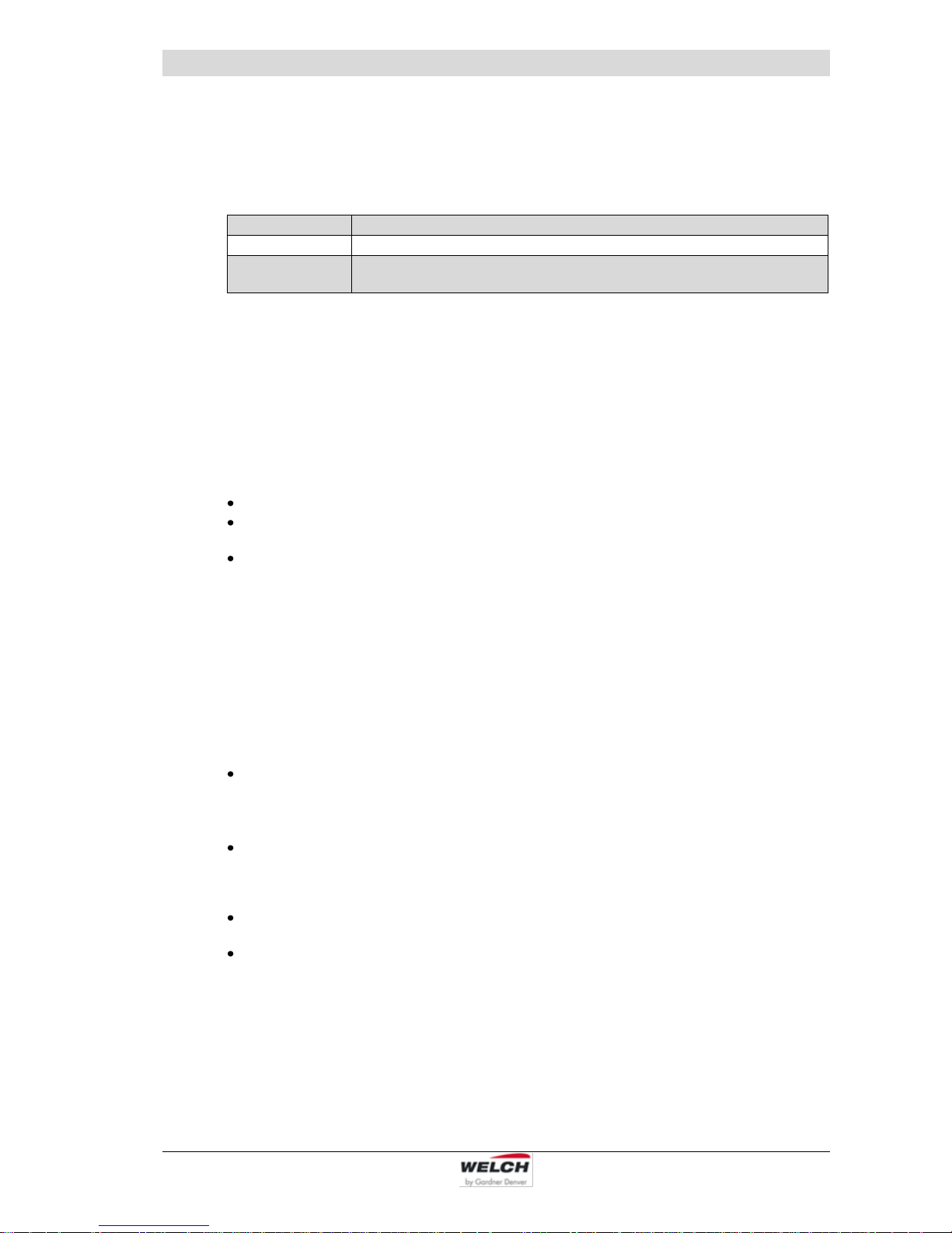
► Materials of the medium-affecting pump parts:
Component
Materials
Seal
EPDM
Screw fitting / Connecting elements
PP, PVDF
Valve
PEEK
Diaphragm
Elastomer + PTFE layer
Vacuum hose
PTFE
Connection head / pump head
PTFE with carbon-fibre reinforcing
*)
*)
electrically conductive (with manufacturer's certificate of electrical conductivity)
Material resistance to aggressive media see: Publisher Hoppenstedt Publishing
(18. September 2007)
► Gas ballast:
When condensable vapours are pumped,
they may be compressed above the
saturated vapour pressure and condense.
Opening the gas ballast valve (17) in the
suction line of the last pump stage allows
air to flow into the pump chamber.
This prevents condensation and flushes
the pump clear.
Operation leads to increasing the ultimate
pressure and the operating temperature.
Fig. 2 Diaphragm pump MPC 301 Z
Description
12 115041
3.1.3 Vacuum Controller 521, intern
In the case of controlled models for laboratory vacuum systems LVS, the vacuum controller,
complete with sensor, venting valve and power unit, is fitted in the device column. The operating and display elements are on the top surface of the column.
(Description and operation see chapter 6, Technical data see chapter 4.3.1)
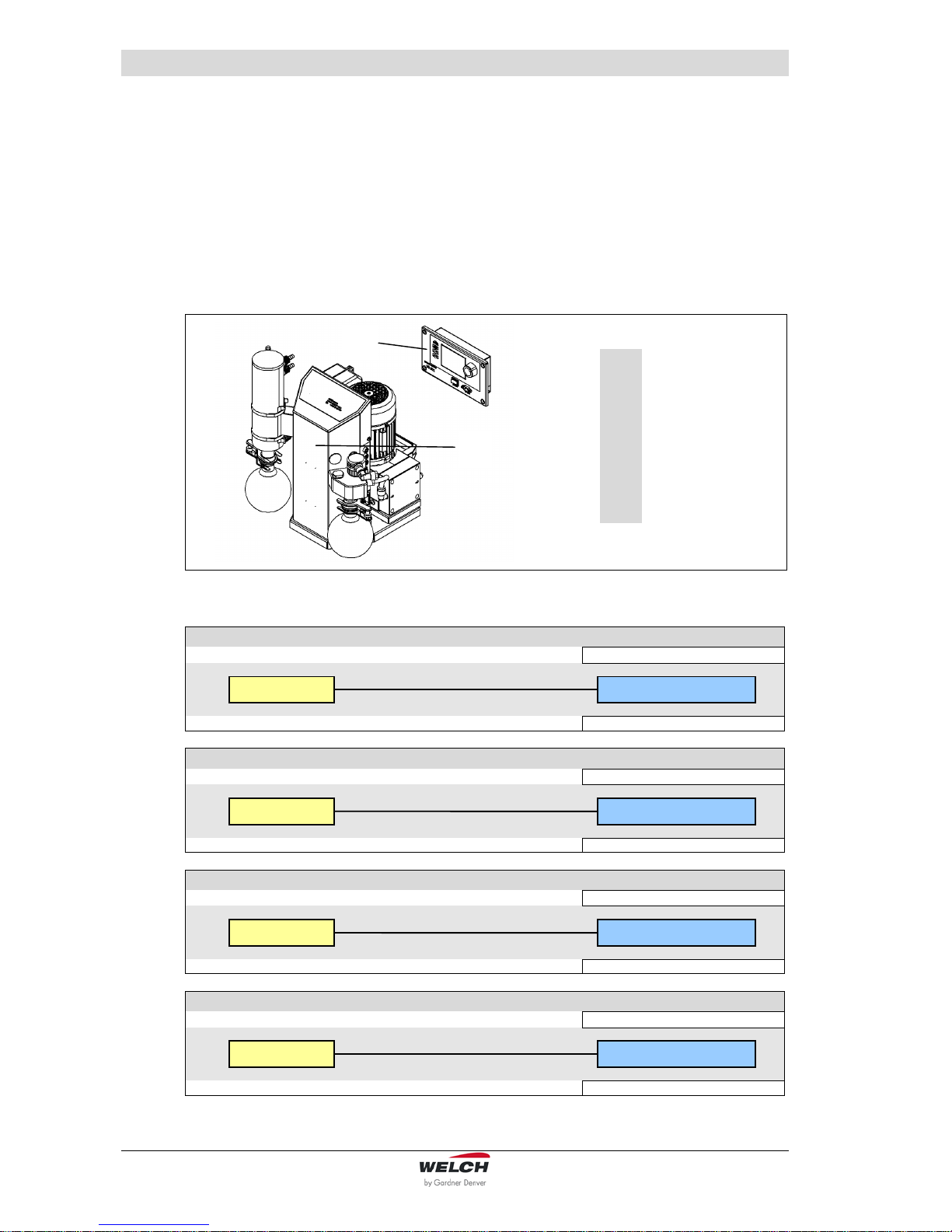
3.1.4 Built-in – Vacuum Controller 521 ef, extern
The LVS 310 Z ef (Order no. 115244-04) is equipped with an external vacuum controller for
installation in, for example, laboratory furniture.
Over the cable to the device, the electrical connection is made.
1
Built-in –
Vacuum Controller
extern
2
LaboratoryVacuum-System
LVS
► Electrical Installation - Built-in – Vacuum Controller 521 ef extern:
K1 Sensor + Venting valve
on the pump - rear panel
Controller
Coupling plug 5 pole
Order no. 600052-06
K2 24 V DC + Water valve
on the pump - rear panel
Controller
Coupling plug 4 pole
Order no. 600052-06
K3 Frequency converter
on the frequency converter - motor
Controller
Coupling plug 4 pole
Order no. 600052-06
K4 Fill level sensor o p t i o n
on sensor fill level
Controller
Order no. 600052-06
4 m
4 m
4 m
4 m
2
1

Description
115041 13
It has the same function as the LVS with a standard assembly. It is operated, as similarly described, via an externally installed controller. On the controller is the on / off power switch
and the RS 232 interface. (see also chapter 9.4)
Dimensions for installation
in laboratory furniture:
3.2 Overview of the variants
Part
Laboratory-Vacuum-Systems LVS
Piece per LVS
300 Z
301 Z
302 Z
310 Z
311 Z
310 Z ef
310 Z en
Suction side
connections for hose DN 8
1
un-
regulated
1
manually
regulated
2
manually
regulated
1
automati-
cally regu-
lated
1 automatically +
1 manually
regulated
1
ecoflex
regulated
1
economic
regulated
Control valve
- - - 1 1 - -
Column complete
1 1 1 1 1 1 1
Diaphragm pump
1 1 1 1 1 1 1
Vacuum controller 521
- - -
1 (cv)
1 (cv)
1 (ef)
1 (en)
Emission condenser
- 1 1 1 1 1 1
Separator 2 1 1 1 1 1
1
Pressure side
connection for hose DN 8
1 1 1 1 1 1 1
Frequency changer
- - - - - 1 -
Special variants, additional with:
- Dial gauge analog
- 1 - - - - -
- Clamping ring screw
A 10 (netvac 1)
- 1 - 1 - 1 1
- Built-in Controller 521
- - - - - 1 -
3.3 Areas of Application
The Laboratory-Vacuum-Systems is intended for:
vacuum filtration, vacuum distillation and vacuum drying
use in physical and chemical laboratories in trade and industry
pumping and compressing neutral and aggressive gases and vapours
generating a vacuum up to an ultimate pressure of < 8 mbar
► Special designs:
Special LVS can be supplied after consultation with the manufacturer or for a corresponding supply
contract.
Motors for different voltages.
3.4 Scope of Delivery
The scope of delivery is specified in the supply contract.
Description
14 115041
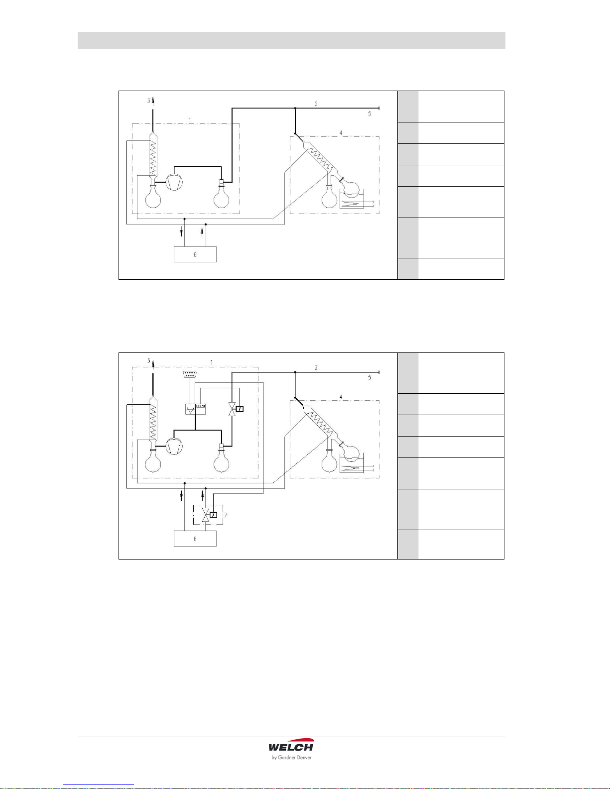
3.5 Examples of application
1
LVS without
vacuum controller
2
Suction line *
3
Outgoing air
4
Rotary vaporizer *
5
Capable of expansion up to 4 loads
6
Coolant system,
un pressurised run
back *
7
Water valve WV *
Fig. 3 Example of application - LVS manually regulated
1
LVS with vacuum
controller and
control valve (cv)
2
Suction line *
3
Outgoing air
4
Rotary vaporizer *
5
Capable of expansion up to 4 loads
6
Coolant system,
un pressurised run
back *
7
Water valve WV *
Fig. 4 Example of application – LVS „cv“ (Control valve) automatically regulated
* Not included in the scope of delivery

Description
115041 15
1
LVS ef (ecoflex)
2
Suction line *
3
Outgoing air
4
Rotary vaporizer *
5
frequency-regulated
pump motor
6
Coolant system,
un pressurised run
back *
7
Water valve WV *
Fig. 5 Example of application – LVS „ef“ ecoflex
1
LVS en (economic)
2
Suction line *
3
Outgoing air
4
Rotary vaporizer *
5
Capable of expansion up to 4 loads
(depending on the
suction capacity)
6
Coolant system,
un pressurised run
back *
7
Water valve WV *
Fig. 6 Example of application – LVS „en“ economic
CAUTION !
The economic Laboratory Vacuum System "LVS ... en" is suitable for slow
processes and central laboratory supplies using a large hysteresis (< 50 mbar).
When installing the switch interval of the diaphragm pump is to be checked.
In practical applications the time-out must be at least 0.5 minutes.
The integrated pressure monitor guarantees immediate activation of the vacuum
generator when required.
This ensures continuous readiness of the vacuum system in the laboratory.

Description
16 115041
3.6 Accessories
The use of chemical-resistant vacuum connections “netvac +” is recommended for extending the application range of a vacuum generator to several workstations.
netvac +
Set BC1 - 63
Order no. 700563
for mounting
on wood furniture
Set BC2 - 63
Order no. 700563-01
for mounting
on sheet metal wall
with integrated FFKM-Check valve, Dosing valve, Hose nozzle
and Ball valve
Area of application: Laboratory
Suction connection: Hose DN 8-10
Connection thread: 1/4 "- outside
Material of valve body: Polypropylene (PP)
Dimensions (W/D/H): Ø 69 / 161 / 82 mm
Mounting hole: Ø 25 to Ø 35 mm
netvac +
Set BC1 - 62
Order no. 700562
for mounting
on wood furniture
Set BC2 - 62
Order no. 700562-01
for mounting
on sheet metal wall
with integrated FFKM-Check valve, Dosing valve and Hose nozzle
Area of application: Laboratory
Suction connection: Hose DN 8-10
Connection thread: 1/4 "- outside
Material of valve body: Polypropylene (PP)
Dimensions (W/D/H): Ø 69 / 69 / 82 mm
Mounting hole: Ø 25 to Ø 35 mm
Vacuum Control-Box
VCB 521 cv
Order no. 600053
Table model as digital, chemical-resistant vacuum regulator.
With integrated sensor, airing -, control- and check valve.
Connection vacuum apparatus: DN 8
Connection vacuum pump: DN 8
Connection inert gas: DN 4
Connection water valve: Binder plug 4-pole 24V DC
Operating software „WELCH-Control 521“
on CD
Order no. 620637
to connect the vacuum controller to the PC
Description
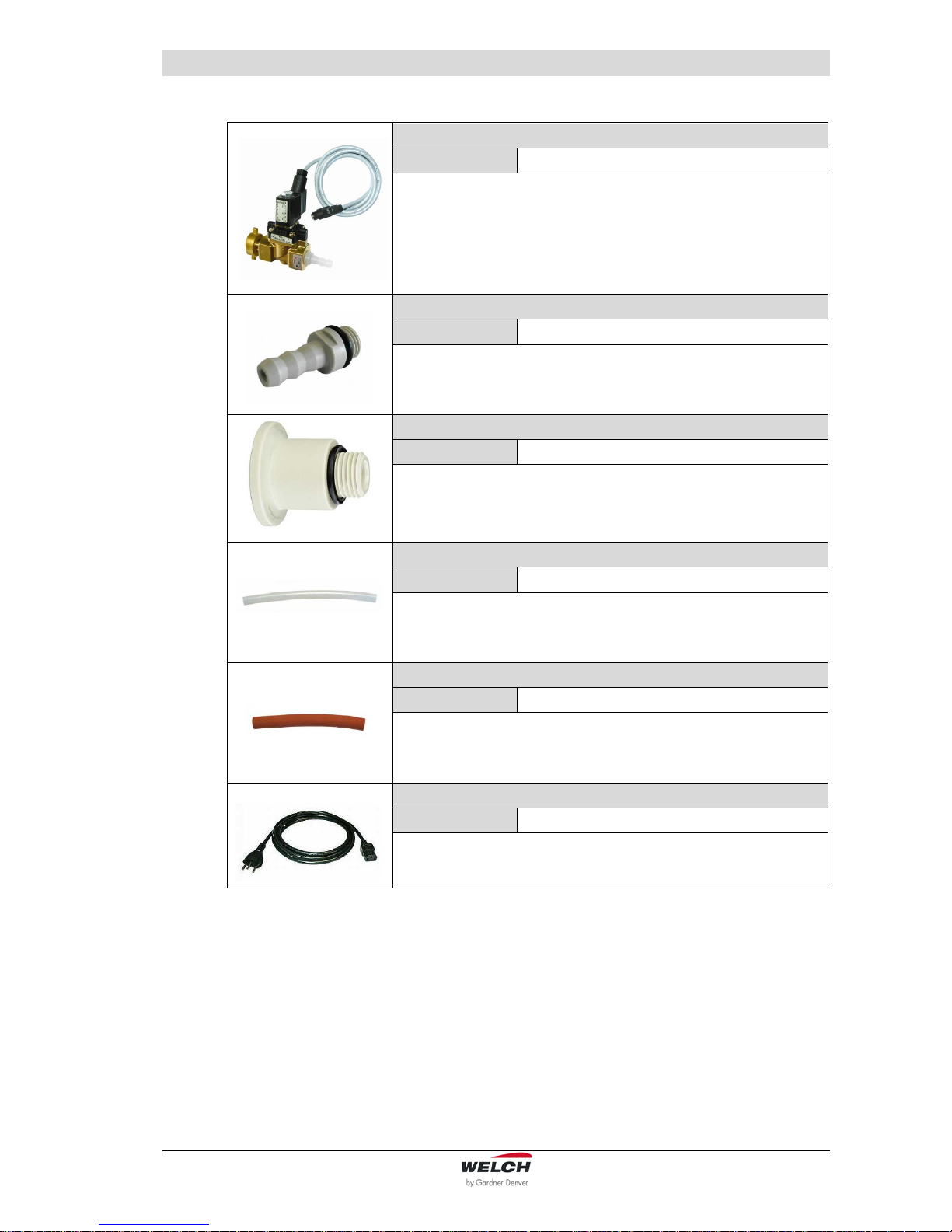
115041 17
Water valve
WV 2
Order no. 700300-02
2 way water flow valve for the demand-responsive cooling water
supply, mounting possible in any direction.
Input: G 3/4 inch sleeve nut
Output: Hose nozzle for hose inside diameters 8 mm
Hose nozzle with FKM - O-Ring
DN 10
Order no. 710955
Material: PP
Male thread: ¼“
Inlet fitting
DN 16 KF
Order no. 710116
Material: PP
Male thread: ¼“
Vacuum hose
10 / 8x1
Order no. 828332
Material: PTFE
Please state the length you want to order!
Vacuum hose
18 / 8x5
Order no. 828310-4
Material: Rubber, red
Please state the length you want to order!
Mains connection cable IEC with plug
Type 12 (CH)
Order no. 825877
for LVS … in 23O V

Technical Data
18 115041
4 Technical Data
4.1 View of device and dimensions
The main dimensions are identical for all types stated here.
Fig. 7 View of device (Model LVS 301 Z, dimensions see chapter 4.3
4.2 Intake Pressure / Pumping Speed – Diagram
Fig. 8 Intake Pressure / Pumping Speed – Diagram
(W)
(H)
(D)

Technical Data
115041 19
4.3 Device data
4.3.1 Laboratory Vacuum Systems
Parameter
Unit
LVS
300 Z
301 Z
302 Z
310 Z
311 Z
Pumping speed 50/60 Hz
DIN 28432
at speed of 1500 rpm
m3 / h
2.3 / 2.5
Ultimate pressure
at speed of 1500 rpm
mbar
8
Ultimate pressure
with gas ballast
at speed of 1500 rpm
18
Max. inlet pressure
bar
1
Max. outlet pressure
1
Intake and pressure ports
-
Hose nozzle DN 8
for hose inside diameter 8 mm
Ambient temperature
°C
+ 10 to + 40
Max. Operating
gas temperature
+ 60
Bearing
-
maintenance-free
Reference surface
sound pressure level
DIN EN ISO 2151
dB (A)
44
Voltage / Frequency
(different data upon
customer request)
V, Hz
230, 50/60 (115, 50/60)
(generally with motor protection switch, switch and cable)
Motor power
W
180
Operating mode
-
S 1
Motor / Type of protection
DIN EN 60529
IP 54
Motor / Class of insulation
DIN EN 600034-1
F (160°C)
Type Examination
Certificate no.
WELCH_ATEX_03-01
Designation EX
II3G IIC T3 X (internal Atm. only)
Dimensions (W/D/H)
mm
360 / 310
/ 395
360 / 310 / 445
Weight
kg
16.1
16.3
16.9
17.8
18.1
Order numbers for :
-
in 230 V
inclusive mains connection cable
IEC with plug CEE, UK
- LVS …
- LVS … with dial gauge analog
- LVS … netvac 1
115041
-
-
115047
115047-10
115047-02
115043
-
-
115044
-
-
115045
-
-
in 115 V
inclusive mains connection cable
IEC with plug US
- LVS …
- LVS … with dial gauge analog
- LVS … netvac 1
115041-01
-
-
115047-01
115047-11
115047-03
115043-01
-
-
115044-01
-
-
115045-01
-
-
in 100 V
inclusive mains connection cable
IEC with plug J
- LVS …
- LVS … with dial gauge analog
115041-05
-
115047-05
115047-12
115043-05
-
115044-05
-
115045-05
-

Technical Data
20 115041
Parameter
Unit
LVS 310 Z ef
LVS 310 Z en
Pumping speed 50/60 Hz
DIN 28432
at speed of 1500 rpm
m3 / h
2.6
2.3 / 2.5
Ultimate pressure
at speed of 1500 rpm
mbar
8
Ultimate pressure
with gas ballast
at speed of 1500 rpm
18
Max. inlet pressure
bar
1
Max. outlet pressure
1
Intake and pressure ports
-
Hose nozzle DN 8
for hose inside diameter 8 mm
Ambient temperature
°C
+ 10 to + 40
Max. Operating gas temperature
+ 60
Bearing
-
maintenance-free
Reference surface sound
pressure level
DIN EN ISO 2151
dB (A)
44
Voltage / Frequency
(different data upon customer request)
V, Hz
230, 50/60 (115, 50/60)
(generally with motor protection switch, switch and cable)
Motor power
W
180
Input Frequency changer
(Apparent power)
W / A
680 / 4.5
-
Operating mode
-
S 1
Type of protection (motor)
DIN EN 60529
IP 54
Motor / Class of insulation
DIN EN 600034-1
F (160°C)
Type Examination Certificate
no.
WELCH_ATEX_03-01
Designation EX
II3G IIC T3 X (internal Atm. only)
Dimensions (W/D/H)
mm
360 / 310 / 445
Weight
kg
19.9
17.8
Order numbers for LVS:
-
in 230 V
inclusive mains connection cable
IEC with plug CEE, UK
- LVS …
- LVS … netvac 1
- LVS … with built-in controller
VC 521 extern
115244
115244-03
115244-04
115248
-
in 115 V
inclusive mains connection cable
IEC with plug US
- LVS …
115244-01
115248-01
 Loading...