

Page 1
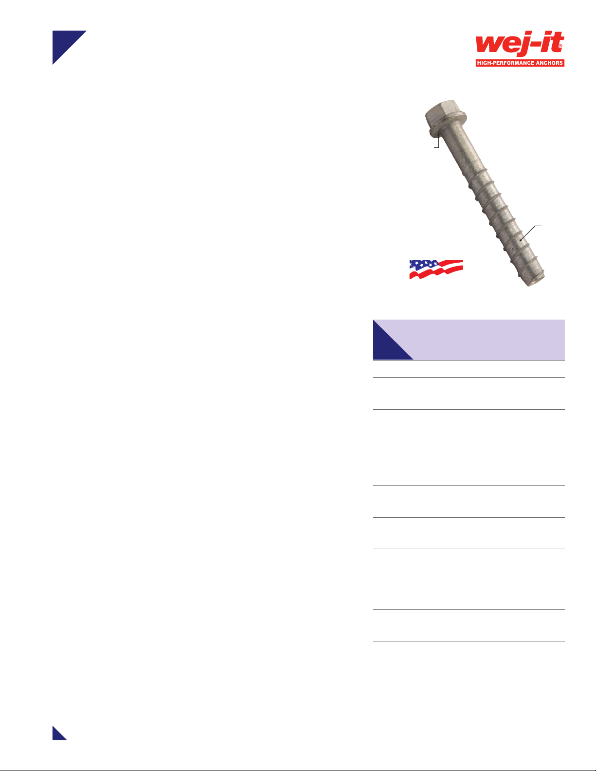
POWER-Skru™ Large Diameter
USA ENGINEERED
Concrete Screw
Description
The POWER-Skru Large Diameter Concrete Screw is a highstrength screw anchor with self-tapping threads that oer a
unique undercutting design for anchoring into concrete and
masonry. No secondary setting is needed. The POWER-Skru
Large Diameter Concrete Screw provides high-strength
performance with low installation torque. A heavyduty mechanically-galvanized nish is available to enhance
corrosion resistance.
Key Features & Benets
Electroplated zinc or heavy-duty mechanically
galvanized nish available
Heat treatment provides surface and core hardness
One-piece design with nished washer head
underhead
serrations
special
thread
design
– No nuts and washers to assemble prior to installation
Serrated head facilitates a positive lock between bolt and
application surface for enhanced
– Vibration and shock resistance
Hardened, self-tapping threads feature a revolutionary
undercutting design
– Allows for immediate load application
– Reduces required installation torque
Can be removed and reinstalled – ideal for temporary
anchoring applications and those requiring service
Anchor length is stamped on head to ease identication
pre- and post-installation
Easier and faster installation than mechanical
expansion anchors
– Bolt Size is Hole Size®
– Prepare hole with lower-cost ANSI B212.15 standard bit –
no metric or o-size bits needed
Less spacing and edge distance requirements - no
expansion forces applied to base material
Specications, Listings
and Approvals
Diameters: 1/4" – 3/4"
Anchor Body: Heat-treated
carbon steel
Finish:
– Electroplated zinc-plated to ASTM
B633, Type III, SC1 (1/4" dia. only)
– Mechanically galvanized to ASTM
B695, Class 65, Type 1 (all sizes)
Threads: Self-tapping threads with
special undercutting design
Head Style: One-piece hex washer
head with locking serrations
Application Materials: Normal
weight concrete, lightweight concrete,
solid masonry; may be suitable for
hollow masonry
Specs: Tested in accordance with
ASTM E488
Applications
Racking
Railing Sill Plates
Stadium Seating
1-203-857-2200 • www.wejit.com Page 1 of 5
Tilt-Up Braces
Formwork
Anchoring Equipment
Page 2
POWER-Skru™ Large Diameter Concrete Screw
Installation
(ft-lbs.)
Min.
Hole (in.)
Critical
(in.)
Washer
(in.)
Installation Information
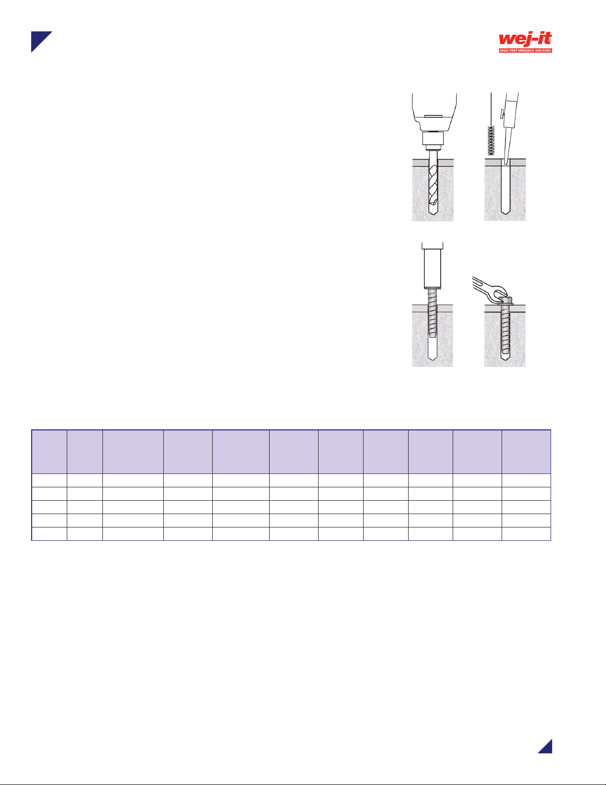
Installation Instructions
1. Using the proper size carbide bit, drill a pilot hole at least 1/2"
deeper than the desired anchor embedment.
2. Clean the hole using a nylon brush and compressed air.
3. Solid Concrete: Using an electric impact wrench, or socket
wrench, insert anchor through the xture into hole and tighten
anchor until fully seated. If using an electric impact wrench, start
on light torque setting to prevent over-torquing or damaging
threads.
3b. Concrete Block (CMU) Using a socket wrench insert anchor
into hole and hand tighten anchor until fully seated. Do not use
an impact wrench for installation into CMU walls.
NOTE: Always wear safety glasses.
1
2
3 3b
Installation Data
Anchor
Drill Bit
Dia.
(in.)
1/4 1/4 8 7/16 3/8 2 3/4 3 1 1/4 1/2
3/8 3/8 25 9/16 1/ 2 3 1-1/8 4-1/2 1-1/2 3/8 3/4
1/2 1/2 55 3/4 5/8 4 1-1/2 6 2 31/64 1
5/8 5/8 95 15/16 3/4 5 1-7/8 7-1/2 2-1/2 19/32 1-5/32
3/4 3/4 150 1-1/8 7/8 6 2-1/4 9 3 45/64 1-3/8
Dia.
(in.)
Torque
Approx.
Wrench
Socket
Size (in.)
Baseplate
Clearance
Edge
Distance
Min.Edge
Distance
(in.)
Critical
Spacing
(in.)
Min.
Spacing
(in.)
Head &
Washer
Height (in.)
Outer Dia.,
Approx.
Page 2 of 5
1-203-857-2200 • www.wejit.com
Page 3

POWER-Skru™ Large Diameter Concrete Screw
Embedment
cr
Min. Spacing S
min
1
1-1/222-1/ 2
3
min
Performance Data
Ultimate and Allowable Loads (lbs.) – Normal-Weight Concrete
Anchor
Dia. (in.)
Drill Bit
Dia. (in.)
Depth (in.)
3,000 psi 6,000 psi 3,000 psi 6,000 psi
Ten sio n Shear Tens ion Shear Tens ion Shear Tens ion Shear
1/4 1/4
3/8 3/8
1/2 1/ 2
5/8 5/8
3/4 3/4
Note: The data presented in this table is based on independent laboratory testing at critical anchor spacing and edge distance
*Tested in accordance with ASTM E488
*Allowable load capacities are calculated using an applied safety factor of 4:1
1-3/16 19 0 428 258 670 760 1710 1030 2680
2-1/2 600 443 863 713 2400 1770 3450 2850
2 920 890 1063 2060 3680 3560 4250 8240
3-1/2 2085 2048 2788 3008 8340 8190 11150 12030
2 853 1088 119 0 2268 3410 4350 4760 9070
3-1/2 2190 2235 3008 3668 8760 8940 12030 14670
2-1/2 873 119 0 117 3 3163 3490 4760 4690 12650
3-1/2 2325 2390 3340 5915 9300 9560 13360 23660
2-1/2 1078 1570 176 0 3535 4310 6280 7040 14140
5-3/4 3290 3960 6753 7933 1316 0 15840 27010 317 3 0
Load Adjustment Factors
Allowable Ultimate
Spacing – Tension
Anchor Dia. 1/4 3/8 1/2 5/8 3/4
Critical Spacing S
1-1/2 0.63 0.50 - - -
2-1/2 0.89 0.66 0.56 0.50 -
Actual Spacing
S
act
4-1/2 - 1.00 0.80 0.76 0.63
7-1/2 - - - 1.00 0.90
Spacing – Shear
Anchor Dia. 1/4 3/8 1/2 5/8 3/4
Critical Spacing S
Min. Spacing S
1-1/2 0.81 0.75 - - -
Actual Spacing
S
act
2-1/2 0.93 0.83 0.78 0.75 -
4-1/2 - 1.00 0.90 0.86 0.80
7-1/2 - - - 1.00 0.95
3 4-1/2 6 7-1/2 9
1 0.50 - - - -
2 0.77 0.57 0.50 - -
3 1.0 0 0.74 0.62 0.56 0.50
6 - - 1.00 0.87 0.77
9 - - - - 1.00
cr
3 4-1/2 6 7-1/2 9
1 1-1/2 2 2-1/2 3
1 0.75 - - - -
2 0.87 0.79 0.75 - -
3 1.0 0 0.87 0.81 0.78 0.75
6 - - 1.00 0.94 0.89
9 - - - - 1.00
For tension anchor loads (lbs.) the critical spacing
is equal to 12 anchor diameters at which the
anchor achieves 100% of load. Minimum spacing
is equal to 4 anchor diameters at which the anchor
achieves 50% of load.
For Shear anchor loads the critical spacing (
equal to 12 anchor diameters at which the anchor
achieves 100% of load. Minimum spacing (s
equal to 4 anchor diameters at which the anchor
achieves 75% of load.
scr
min
) is
) is
1-203-857-2200 • www.wejit.com
Page 3 of 5
Page 4

POWER-Skru™ Large Diameter Concrete Screw
min
min
Load Adjustment Factors
Edge Distance – Tension
Anchor Dia. 1/4 3/8 1/2 5/8 3/4
Critical Edge Dist. C
cr
Min. Edge Dist. C
3/4 0.70 - - - -
1-1/8 0.78 0.70 - - -
1-1/2 0.86 0.76 0.70 - -
1-7/8 0.97 0.82 0 .74 0.70 -
Actual Edge
Dist. C
act
2 1.0 0 0.85 0.76 0.72
2-1/4 - 0.90 0.80 0.76 0.70
3 - 1.00 0.89 0.81 0.75
4 - - 1.00 0.91 0.84
5 - - - 1.00 0.92
6 - - - - 1.00
Edge Distance – Shear
Anchor Dia. 1/4 3/8 1/2 5/8 3/4
Critical Edge Dist. C
Min. Edge Dist. C
Actual Edge
Dist. C
act
cr
3/4 0.15 - - - -
1-1/8 0.29 0.15 - - -
1-1/2 0.42 0.25 0 .15 - -
1-7/8 0.57 0.35 0.23 0.15 -
2-1/4 0.72 0.46 0.31 0.21 0.15
3 1.0 0 0.62 0.45 0.32 0.25
4-1/2 - 1.00 0.75 0.56 0.46
6 - - 1.00 0.77 0.65
7-1/2 - - - 1.00 0.84
9 - - - - 1.00
2 3 4 5 6
3/4 1-1/8 1-1/2 1-7/8 2-1/4
3 4-1/2 6 7-1/2 9
3/4 1-1/8 1-1/2 1-7/8 2 -1/4
For tension anchor loads the critical edge distance
(
) is equal to 8 anchor diameters at which the
ccr
anchor achieves 100% of load. Minimum edge
distance (c
which the anchor achieves 70% of load.
For hear anchor loads the critical edge distance
(
) is equal to 12 anchor diameters at which the
ccr
anchor achieves 100% of load. Minimum edge
distance (c
which the anchor achieves 15% of load.
) is equal to 3 anchor diameters at
min
) is equal to 3 anchor diameters at
min
Page 4 of 5
1-203-857-2200 • www.wejit.com
Page 5

Order Information
COMING SOON!
®
POWER-Skru™ Large Diameter Concrete Screw
Zinc Electroplated, Heat-Treated Carbon Steel
Catalog
No.
ATEZ1413 1/4 x 1-3/4 1/4 3/8 100 800
ATE Z1421 1/4 x 2-1/4 1/4 3/8 10 0 800
ATE Z1430 1/4 x 3 1/4 3/8 100 800
Anchor
Size
(in.)
Drill Bit
Dia.
(in.)
Baseplate
Clearance
Hole (in.)
Box
Quantity
Carton
Quantity
Large Diameter Concrete Screws:
Type 316 Stainless Steel
Mechanically Galvanized, Heat-Treated Carbon Steel
Catalog
No.
ATEZG1413 1/4 x 1-3/4 1/4 3/8 100 800
ATE ZG1421 1/4 x 2-1/4 1/4 3/8 100 800
ATE ZG1430 1/4 x 3 1/4 3/8 100 800
ATEZG3830 3/8 x 3 3/8 1/2 50 400
ATE ZG3840 3/8 x 4 3/8 1/2 50 400
ATE ZG3850 3/8 x 5 3/8 1/2 25 200
ATEZG3860 3/8 x 6 3/8 1/2 25 200
ATEZG12 3 0 1/2 x 3 1/2 5/8 20 160
ATEZG1240 1/2 x 4 1/2 5/8 20 160
ATEZG12 50 1/2 x 5 1/2 5/8 20 160
ATEZG12 6 0 1/2 x 6 1/2 5/8 20 160
ATEZG1270 1/2 x 7 1/2 5/8 20 160
ATE ZG5840 5/8 x 4 5/8 3/4 10 80
ATE ZG5850 5/8 x 5 5/8 3/4 10 80
ATEZG5860 5/8 x 6 5/8 3/4 10 80
ATE ZG5870 5/8 x 7 5/8 3/4 10 80
ATEZG5880 5/8 x 8 5/8 3/4 10 40
ATE ZG3440 3/4 x 4 3/4 7/8 10 80
ATE ZG3450 3/4 x 5 3/4 7/8 10 80
ATE ZG3460 3/4 x 6 3/4 7/8 10 60
ATE ZG3470 3/4 x 7 3/4 7/8 5 30
Anchor
Size
(in.)
Drill Bit
Dia.
(in.)
Baseplate
Clearance
Hole (in.)
Box
Quantity
Carton
Quantity
For more information, please contact:
Divisions of Mechanical Plastics Corp.
110 Richards Avenue • Norwalk, CT 06854
Phone: 203-857-2200
Fax: 203-857-2201 • E-mail: sales@wejit.com
www.toggler.com • www.wejit.com
TOGGLER logo and typface, Wej-It®, POWER-Skru™, Bolt Size is Hole Size™, and High-Performance Anchors®
are trademarks of Mechanical Plastics Corp. ©2015 Mechanical Plastics Corp. Rev. 6/15
Page 5 of 5
 Loading...