

WEITRON MMBTA94 Schematic [ru]
MMBTA94
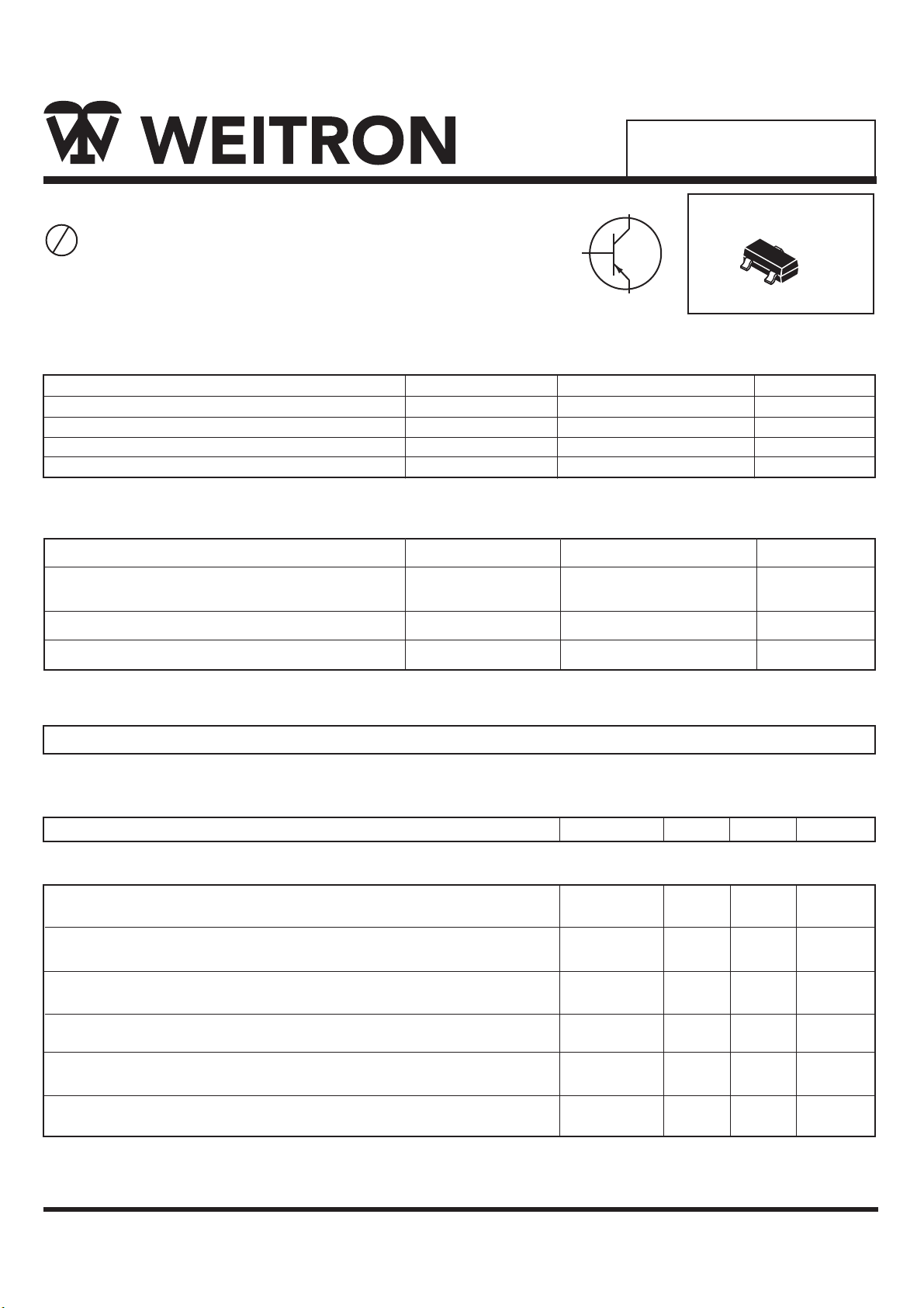
High-Voltage PNP Transistor Surface Mount
P b
Lead(Pb)-Free
Maximum Ratings
Rating
Collector-Emitter Voltage
Collector-Base Voltage
Emitter-Base Voltage
Collector Current-Continuous
Thermal Characteristics
Characteristics
Maximum Power Dissipation
Total Power Dissipation (Ta=25°C)
Junction Temperature
Storage Temperature
Symbol
V
CEO
V
CBO
V
EBO
I
C
Symbol Max
P
D
T
J
T
stg
1
BASE
COLLECTOR
3
2
EMITTER
Value
350
+150
-55 to +150
-400
-400
-6.0
-150
SOT-23
3
1
2
Unit
Vdc
Vdc
Vdc
mAdc
Unit
mW
°C
°C
Device Marking
MMBTA94=4Z
Electrical Characteristics (T
Characteristics Symbol
=25°C Unless Otherwise noted)
A
Off Characteristics
Collector-Emitter BreakdownVoltage (IC=-1.0mAdc. IB=0)
Collector-Base Breakdown Voltage (IC=-100μAdc, IE=0)
Emitter-Base Breakdown Voltage (IE=-10 uAdc, IC=0)
Collect Cuto Current (VCB= -400Vdc, IE=0)
Emitte Cuto Current (VEB=-6V, IC=0)
Emitte Cuto Current (VCE=-400V, VEB=0V)
V(BR)CEO
V(BR)CBO
V(BR)EBO
I
CBO
I
EBO
I
CES
Min Max
-400
-400
-6.0
-
-
-
-
-
-
-100
-100
-500
Unit
Vdc
Vdc
Vdc
nAdc
nAdc
nAdc
WEITRON
http://www.weitron.com.tw
1/4 Rev.A 11-Jun-06
MMBTA94
Electrical Characteristics (T
Characteristics
On Characteristics
DC Current Gain*
(VCE=-10Vdc, IC= -1.0 mAdc)
(VCE=-10Vdc, IC= -10 mAdc)
(VCE=-10Vdc, IC= -50 mAdc)
(VCE=-10Vdc, IC= -100 mAdc)
Collector-Emitter Saturation Voltage*
(IC= -1.0mAdc, IB= -0.1mAdc)
(IC= -10mAdc, IB= -1mAdc)
(IC= -50mAdc, IB= -5mAdc)
Base-Emitter Saturation Voltage*
(IC= -10 mAdc, IB= -1.0 mAdc)
Output Capacitance
(VCE = -10 Vdc, f=1.0 MHz)
=25˚C unless otherwise noted) (Countinued)
A
Symbol
H
FE(1)
H
FE(2)
H
FE(3)
H
FE(4)
V
CE(sat)
V
BE(sat)
Cob
Min
50
75
60
20
-
-
-
Max
-
-
-
-
4
200
.
0.20
0.30
0.60
0.90
6
Unit
-
Vdc
Vdc
pF
*Pulse Test : Pulse Width ≤ 380μS, Duty Cycle ≤ 2.0%.
WEITRON
http://www.weitron.com.tw
2/4 Rev.A 11-Jun-06
 Loading...