

Weiss Engineering TC 150T, TC 220, TC 220T, TC 320, TC 1000 Operating Instructions Manual
...
Rundschalttische TC
Rotary Indexing Tables TC
Betriebsanleitung
Operating Instructions

- Für Ihre Notizen -
- For your Notes -
2
WEISS GmbH 03/2002

Lesen Sie diese Betriebsanleitung sorgfältig
durch und bewahren Sie sie zum späteren
Nachschlagen gut auf.
Machen Sie sich insbesondere als erstes mit
den Sicherheitsvorschriften vertraut.
Stand: März 2002
WEISS GmbH
Sondermaschinentechnik
Siemensstrasse 17
D-74722 Buchen/Odw.
Tel.: +49 (0) 6281 / 5208-0
Fax: +49 (0) 6281 / 9150
eMail: info@weiss-gmbh.de
Internet: http://www.weiss-gmbh.de
Technische Änderungen vorbehalten.
Please study these Operating Instructions
very carefully and keep them as reference.
First of all please familiarize yourself with the
safety instructions.
Release: March 2002
WEISS GmbH
Sondermaschinentechnik
Siemensstrasse 17
D-74722 Buchen/Odw.
Tel.: +49 (0) 6281 / 5208-0
Fax: +49 (0) 6281 / 9150
eMail: info@weiss-gmbh.de
Internet: http://www.weiss-gmbh.de
We reserve the right to change or discontinue
specifications without prior notice.
WEISS GmbH 03/2002 3

Inhaltsverzeichnis
1 Sicherheitsvorschriften 7
1.1 Bestimmungsgemässe Verwendung 7
1.2 Erläuterung der verwendeten Symbole 7
1.3 Sicherheitsbestimmungen 7
2 Beschreibung der Rundschalt-
tische 11
2.1 Mechanik 11
2.2 Antrieb 12
2.3 Einbaulagen der Rundschalttische und
Anbau des Motors (Antriebslage) 13
2.4 Positionsnocken/Näherungsschalter 15
2.5 Dauermagnetbremse 16
2.6 Verändern der Schaltzeit 17
3 Steuern der Rundschalttische 19
3.1 Allgemeine Funktionsweise 19
3.2 Steuern mit der Steuerkarte TS 002 E 20
3.3 Steuern mit der Steuerung EF xxx 22
3.4 Steuerungsablauf mit Fremdsteuerung
(SPS) 24
3.5 Anschluss von Steuerung,
Motor und Bremse 26
Bremsmotor Normalbetrieb (24V Bremse) 26
Bremsmotor Pendelbetrieb (24V Bremse) 27
Schaltungsbeispiel für
langsamlaufende Rundschalttische 29
Schaltungsbeispiel für
schnelllaufende Rundschalttische 30
Anschluss der Steuerung EF 037/1 31
Anschluss der Steuerungen
EF 150/3, EF 220/3, EF 300/3 32
4 Inbetriebnahme 33
4.1 Sicherheitsbestimmungen 33
4.2 Elektrische Vorbereitungen 34
4.3 Entlüftungsschraube/Verschlussstopfen 35
4.4 Allgemeines Vorgehen zur Inbetriebnahme 36
4.5 Montage von Zusatzschalttellern 36
Table of Contents
1 Safety instructions 7
1.1 Intended Use 7
1.2 Explanation of Symbols 7
1.3 Safety Regulations 7
2 Description of the Indexers
11
2.1 Mechanics 11
2.2 Drive 12
2.3 Mounting Position of Indexer and
drive Position 13
2.4 Cam & Limit Switch 15
2.5 Magnetic Brake 16
2.6 Change of Index Time 17
3 Control of Indexers 19
3.1 Function in general 19
3.2 Control with the Controller Card TS 002 E 20
3.3 Control with the Controller Card EF xxx 22
3.4 Control Sequence with PLC 24
3.5 Control, Drive Motor and Brake Wiring 26
Brake Motor Normal Operation 26
Brake Motor Reciprocating Operation 27
Example for slow cycling indexing tables 29
Example for fast cycling indexing tables 30
Wiring of Controller Card EF 037/1 31
Wiring of Controller Cards
EF 150/3, EF 220/3, EF 300/3 32
4 Start-Up 33
4.1 Safety regulations 33
4.2 Electrical Preparations 34
4.3 Breather Valve 35
4.4 General Start-Up 36
4.5 Installation of Tooling Plate 36
4
WEISS GmbH 03/2002

5 Wartung 37
5.1 Einstellung der Bremse bei Bremsmotoren 37
5.2 Bremse ersetzen 39
5.3 Motor ersetzen 40
5.4 Zahnriemen ersetzen 42
5.5 Näherungsinitiator ersetzen 43
5.6 Schmierstoffe 43
6 Störungsbehebung 45
6.1 Störungsbehebung bei der
Rundschalttischsteuerung TS 002 E 45
Fehleranzeige "Position überfahren" 45
Fehleranzeige "Motor Überlast" 46
Fehleranzeige "Kurzschluss" 47
6.2 Störungsbehebung bei der
Rundschalttischsteuerung EF xxx 48
7 Ersatzteile 49
8 Entsorgung und Recycling 51
A Anhang 53
5 Maintenance 37
5.1 Adjustment of Brake on Brake-Motor 37
5.2 Replace Brake 39
5.3 Replace motor 40
5.4 Replace Timing Belt 42
5.5 Replace Limit Switch 43
5.6 Lubrication 43
6 Troubleshooting 45
6.1 Troubleshooting Control Card TS 002 E 45
Fault Message “Position Over Run” 45
Fault Message “Motor Overload” 46
Fault message “Electrical Short” 47
6.2 Troubleshooting the Control CArd EF xxx 48
7 Spare Parts 49
8 Disposal and Recycling 51
A Appendix 53
A.1 Zusatzinformationen
Ringrundschalttische TR und NR 53
A.2 Zusatzinformationen
Ringrundschalttisch NR 56
A.1 Additional information
Indexing Rings TR and NR 53
A.2 Additional information
Indexing Ring NR 56
WEISS GmbH 03/2002 5

- Für Ihre Notizen -
- For your Notes -
6
WEISS GmbH 03/2002
1 Sicherheitsvorschriften
1.1 Bestimmungsgemäße Verwendung
Die Rundschalttische der TC-Typenreihe sind
ausschließlich für getaktete Drehbewegungen
einer Nutzlast bestimmt, welche bei der Manipulation nicht personen-, sach- und umweltgefährdend reagieren kann. Zudem dürfen die
Rundschalttische einzig im Rahmen der in der
vorliegenden Betriebsanleitung und in den
Verkaufsunterlagen angegebenen Spezifikationen eingesetzt werden. Eine andere oder
darüberhinausgehende Benützung gilt als
nicht bestimmungsgemäss. Zur bestimmungsgemässen Verwendung gehört auch das
Beachten der Betriebsanleitung und das
Einhalten der vom Hersteller
vorgeschriebenen Wartungs- und
Instandsetzungsvorschriften.
1.2 Erklärung der verwendeten Symbole
1 Safety Instructions
1.1 Intended Use
The Model TC indexer is for the exclusive
rotational indexed motion of a payload, which
during operation shall not damage persons,
goods or the environment. The indexer shall
only be used within the limits of these
Operating Instructions and within the
specifications that are included in the sales
contract. The use beyond theses definitions
is determined as outside the limits of
“Intended Use”. Part of the “Intended Use” is
also adherence to the “Operational
Instructions”, “Maintenance Instructions” and
“Trouble Shooting Instructions”.
1.2 Explanations of Symbols
WARNUNG
In dieser Betriebsanleitung haben wir alle
Stellen, die Ihre persönliche Sicherheit
betreffen mit diesem Symbol versehen.
HINWEIS
Unter diesem Symbol erhalten Sie Hinweise
für den sachgerechten Umgang mit dem
Rundschalttisch. Das Nichtbeachten dieser
Hinweise kann zu Störungen am
Rundschalttisch oder der Umgebung führen.
1.3 Sicherheitsbestimmungen
Vor der Inbetriebnahme des
Rundschalttisches ist die Betriebsanleitung
aufmerksam zu lesen.
Der Rundschalttisch darf erst in Betrieb
genommen werden, wenn die Gesamtanlage,
in welche der Rundschalttisch integriert ist,
sowie die Steuerung – speziell das
Sicherheitssystem – der Maschinenrichtlinie
98/37/EG entspricht!
WARNING
Each area, which concerns your personal
safety, shows this symbol.
NOTE
This symbol will draw your attention to the
correct use of the indexer. Non-adherence
can cause trouble for the indexer or the
environment.
1.3 Safety Regulations
Please read the Operation Manual carefully
before Start-Up
The indexer can only be used after the
complete system into which the indexer is
integrated adheres to the control and safety
regulations of “Machine Regulations
98/37/EG”
WEISS GmbH 03/2002 7

WARNUNG
· Drehteller mit hohem Drehmoment!
· Quetschungen oder Verlust von
Gliedmaßen!
· Nie in den Arbeitsbereich des
Drehtellers und seiner Aufbauten
hineingreifen!
WARNUNG
Im Normalbetrieb sind ausreichende
Schutzvorrichtungen, z.B. Schutzgitter,
Abdeckungen, Lichtvorhänge oder
Trittmatten zu installieren, um das
Bedienpersonal vor Verletzungen durch
die Mechanik zu schützen.
Die einschlägigen
Unfallverhütungsvorschriften sowie die
sonstigen allgemein anerkannten
sicherheitstechnischen und arbeitsmedizinischen Vorschriften sind einzuhalten.
Unzulässige Veränderungen und die Verwendung von Ersatzteilen und
Zusatzeinrichtungen, die nicht vom Hersteller
empfohlen werden, können Verletzungen von
Personen oder Sachschäden hervorrufen.
WARNING
· High torque tooling plate!
· Danger of injury or loss of limbs
· Never reach into the work area of the
tooling plate including its tooling!
WARNING
Use protective devices such as
enclosures, covers, light curtains or tread
mats to protect the operator from injury.
Apply the standard rules and regulations for
prevention of accidents as well as health and
safety recommendations.
In all cases any protective devices must
comply with the statutory safety requirements
prevailing in the country of the end user.
Unauthorized modifications and the use of
parts and accessories that are not
recommended by the manufacturer could
cause injury or material damage.
WARNUNG
Vor Einstellungs- und Wartungsarbeiten
ist der Antrieb spannungslos zu schalten
und vor Wiederanlauf zu sichern!
Solche Arbeiten – ob an der Mechanik oder
der Steuerung des Rundschalttisches –
dürfen nur von geschultem Fachpersonal
durchgeführt werden. Geschultes
Fachpersonal sind Personen, die mit der
Aufstellung, Montage, Inbetriebsetzung und
Betrieb des Rundschalttisches vertraut und
über die Gefahren unterrichtet sind.
WARNUNG
Es ist in keinem Fall möglich, den
Rundschalttisch von Hand in eine der
Disconnect the drive before set-up or
maintenance work.
Trained and authorized technicians shall only
perform this type of work on the indexer or its
controls. Trained technicians are persons
who are familiar with the installation, set-up
and use of the indexer and who have been
instructed about the dangers involved.
It is not possible to turn the indexer by
hand in one of the dwell periods.
WARNING
WARNING
möglichen Verriegelungspositionen zu
drehen!
8
WEISS GmbH 03/2002

WARNUNG
Die Rundschalttische dürfen nicht in einer
explosionsgefährdeten Umgebung eingesetzt
werden.
Jeder sicherheitsbedenkliche Einsatz eines
Rundschalttisches ist zu unterlassen!
Die Rundschalttische dürfen weder während
der Lagerung noch während des Betriebes
Flüssigkeiten ausgesetzt sein.
HINWEISE
Die Elektromotoren sind grundsätzlich vor
Überlastung zu schützen. Wir empfehlen den
Einsatz eines Motorschutzschalters mit
elektromagnetischem Schnellauslöser. Als
zusätzliche Absicherung haben unsere
Steuerungen TS 002 E und EF-xxx eine
Zykluszeitüberwachung. Sollten Sie diese
Steueren nicht verwenden, so installieren Sie
bitte in Ihrer Steuerung eine Zykluszeitüberwachung, die nach Auslösen eines Startsignales den Motor abschaltet, wenn nach ca.
doppelter Drehbewegungszeit keine Fertigmeldung durch den induktiven Näherungsschalter "P" erfolgt.
Bei Nichteinhaltung dieser Empfehlungen
können wir keine Garantie für
Motorschäden übernehmen.
Vor der Inbetriebnahme des Rundschalttisches Verschlussstopfen der Entlüftungsschraube entfernen (siehe Kapitel 4.3).
WARNING
The indexers cannot be used in an explosion
hazard environment.
The indexer shall not be used in applications
where safety is compromised.
The indexers shall not be exposed to any
liquids during storage or in use.
NOTES
The drive motors have to be protected against
overload. We recommend the use of a
protective motor switch with a magnetic quickaction circuit breaker. Our control cards
TS 002E and EF-xxx have a cycle time control
as an added safety feature. In case you don’t
use these control cards you should program a
cycle time control in your PLC. The motor
should be disconnected if the limit switch “P”
is not made after a period of double the index
time since the start signal.
We will decline the warranty for the motor
if this recommendation has not been
followed.
Before start-up remove the plug from the
breather valve.
WARNUNG
Transportieren Sie den Rundschalttisch nur
mit einem Hebezeug, welches für das
entsprechende Gewicht ausgelegt ist (siehe
Gewichtstabelle im Kapitel 4.1). Verwenden
Sie für das Befestigen des Rundschalttisches
am Hebezeug Ringschrauben, die der
Belastung sicher standhalten.
Für TC 120 bis TC 320 genügen zwei Ringschrauben, ab TC 500 sind drei
Ringschrauben einzusetzen.
Befestigen Sie die Ringschrauben in den Gewinden des Drehtellers (siehe auch Kapitel
4.1).
WEISS GmbH 03/2002 9
For transportation use only hoists which are
designed for the weight of the indexer. (See
weight table in chapter 4.1). Use eyebolts,
which are strong enough.
Use 2 eyebolts for indexer models TC 120 to
TC 320, use 3 eye bolts for models TC 500
and above.
The dial plates have the correct tapped holes
for the eyebolts (refer to chapter 4.1).
WARNING

WARNUNG
Arbeiten an der elektrischen Installation
dürfen nur von einer Elektrofachkraft oder von
unterwiesenen Personen unter Leitung und
Aufsicht einer Elektrofachkraft ausgeführt
werden. Die fachspezifischen Sicherheitsvorschriften sind zu befolgen.
WARNUNG
Dem Antriebsmotor des Rundschalttisches
sind in jedem Fall
r geeignete NOT-AUS-Einrichtungen
nach EN 60 204-1 (Einrichtungen für
Handlungen im Notfall)
r ein Motorschütz sowie
r ein Motorschutzschalter
vorzuschalten.
Im NOT-AUS-Betrieb muss die
Motorspannung unterbrochen werden.
Die 24V-DC-Versorgungsspannung der
Steuerkarte braucht dagegen nicht
unterbrochen zu werden. In diesem Falle
muss jedoch der RESET/STOP-Eingang der
Steuerkarte deaktiviert werden (Klemme 2:
low-Pegel), um erstens die Bremse zu
schließen und zweitens die zwangsläufig
auftretende Fehlermeldung "Motorüberlast" zu
unterdrücken, falls die
Motorspannungsabschaltung mitten im Zyklus
erfolgt.
Sollten Sie Fragen zum Rundschalttisch
haben – insbesondere auch Fragen zur
Sicherheit –, wenden Sie sich an folgende
Adresse:
WEISS GmbH
Sondermaschinentechnik
Siemensstrasse 17
D-74722 Buchen/Odw.
Tel.: +49 (0) 6281 / 5208-0
Fax: +49 (0) 6281 / 9150
eMail: info@weiss-gmbh.de
Internet: http://www.weiss-gmbh.de
Im Internet können Sie sämtliche Vertreteradressen abrufen.
WARNING
Only electricians or trained personal under
supervision of an electrician shall do the
electrical installation of the indexer. The
specific rules and regulations for electrical
installation are to be followed.
WARNING
The drive motor has to be connected to:
r An E-STOP switch (according to
EN 60-204-1)
r A motor contactor and
r A protective motor switch
In E-STOP the power has to be interrupted.
The 24VDC power for the control card does
not have to be interrupted. In this case the
RESET/STOP input of the control card has to
be deactivated (Connection 2, low level) to
activate the motor brake and to avoid the fault
message “Overload” in case the E-STOP
occurs during index.
For additional questions especially if they are
safety related please contact:
WEISS GmbH
Sondermaschinentechnik
Siemensstrasse 17
D-74722 Buchen/Odw.
Tel.: +49 (0) 6281 / 5208-0
Fax: +49 (0) 6281 / 9150
eMail: info@weiss-gmbh.de
Internet: http://www.weiss-gmbh.de
You will find all addresses of our
representatives on our web page.
10
WEISS GmbH 03/2002

2 Beschreibung der
Rundschalttische
2.1 Mechanik
Die Rundschalttische der TC-Typenreihe
werden von einem Zylinderkurvenschrittgetriebe mit sinoiden Beschleunigungs- und
Bremsverhalten angetrieben. Dadurch wird
ein sehr weiches Anfahren und Abbremsen
erreicht.
Während der Drehphase des Rundtischtellers
rollen die Antriebselemente in der
Kurvenbahn der Antriebskurve (Rollreibung)
ab. In der Verriegelungsphase liegen zwei
Antriebsrollen vorgespannt an der
Antriebskurve an. Die Kurvenrollen sind
nadelgelagert.
2 Description of the Index
Tables
2.1 Mechanics
A cylindrical barrel cam with a sine type
acceleration and deceleration curve rotates
the index tables of the TC series. This allows
for a very soft start and stop operation.
During index the cam followers follow the
groove of the barrel cam in a rolling motion.
During dwell two cam followers touch the
groove under a preload. The cam followers
have needle bearings.
Fig. 2-1
WEISS GmbH 03/2002 11

2.2 Antrieb
Der Antrieb erfolgt standardmäßig für alle
Typen durch Drehstrombremsmotoren mit
24V- Gleichstrom-Bremse.
Der Motor läuft nur während der Drehphase
des Rundschalttisches und wird nach
Erreichen der Verriegelung ausgeschaltet.
Der Kraftfluss verläuft vom Motor über eine
Zahnriemenstufe und ein ein- oder
zweistufiges Zahnradgetriebe direkt auf die
Antriebskurve.
Bei sehr kurzen Bearbeitungszeiten oder
hohen Schalthäufigkeiten (>50/min) wird der
Standardbremsmotor durch einen
Bremsmotor mit selbstnachstellender
Bremse ersetzt (Kobold-Motor).
Als Sonderausführung existieren Drehstrombremsmotoren mit 230V-Wechselstrombremse.
Die technischen Daten der Motoren sind auf
der Auftragsbestätigung, dem Lieferschein
und der Rechnung aufgeführt.
2.2 Drive
The standard drive is a 3-phase brake motor
with a 24VDC brake
The motor runs only during the index phase
and will be switched after reaching dwell.
The power is transmitted from the motor
through a timing belt via a one or two-step
gear transmission to the barrel cam.
For applications with very short dwell times or
high index rates (>50/min) the standard brake
motor will be replaced through a brake motor
with a self adjusting brake (Kobold -Motor).
As a special we offer a 3-phase brake motors
with a 230 VAC brake.
The specifications of the drive motors a listed
on the order confirmation, the shipping papers
and the invoice.
HINWEIS
Die Elektromotoren sind grundsätzlich vor
Überlastung zu schützen. Wir empfehlen den
Einsatz eines Motorschutzschalters mit
elektromagnetischem Schnellauslöser. Als
zusätzliche Absicherung hat unsere
Steuerkarte TS 002 E eine
Zykluszeitüberwachung. Sollten Sie diese
Steuerkarte nicht verwenden, so installieren
Sie bitte in Ihrer Steuerung eine
Zykluszeitüberwachung, die nach Auslösen
eines Startsignales den Motor abschaltet,
wenn nach ca. dreifacher Drehbewegungszeit
keine Fertigmeldung durch den induktiven
Näherungsschalter "P" erfolgt.
Bei Nichteinhaltung dieser Empfehlungen
können wir keine Garantie für
Motorschäden übernehmen.
NOTE
The drive motors have to be protected against
overload. We recommend the use of a
protective motor switch with a magnetic quickaction circuit breaker. Our Control Card TS
002E has a cycle time control as an added
safety feature. In case you don’t use the
control card you should program a cycle time
control in your PLC. The motor will be
disconnected if the limit switch “P” is not
triggered after triple the index time has
passed since the start signal.
We will decline the warranty for the motor
if this recommendation is not being
followed.
12
WEISS GmbH 03/2002

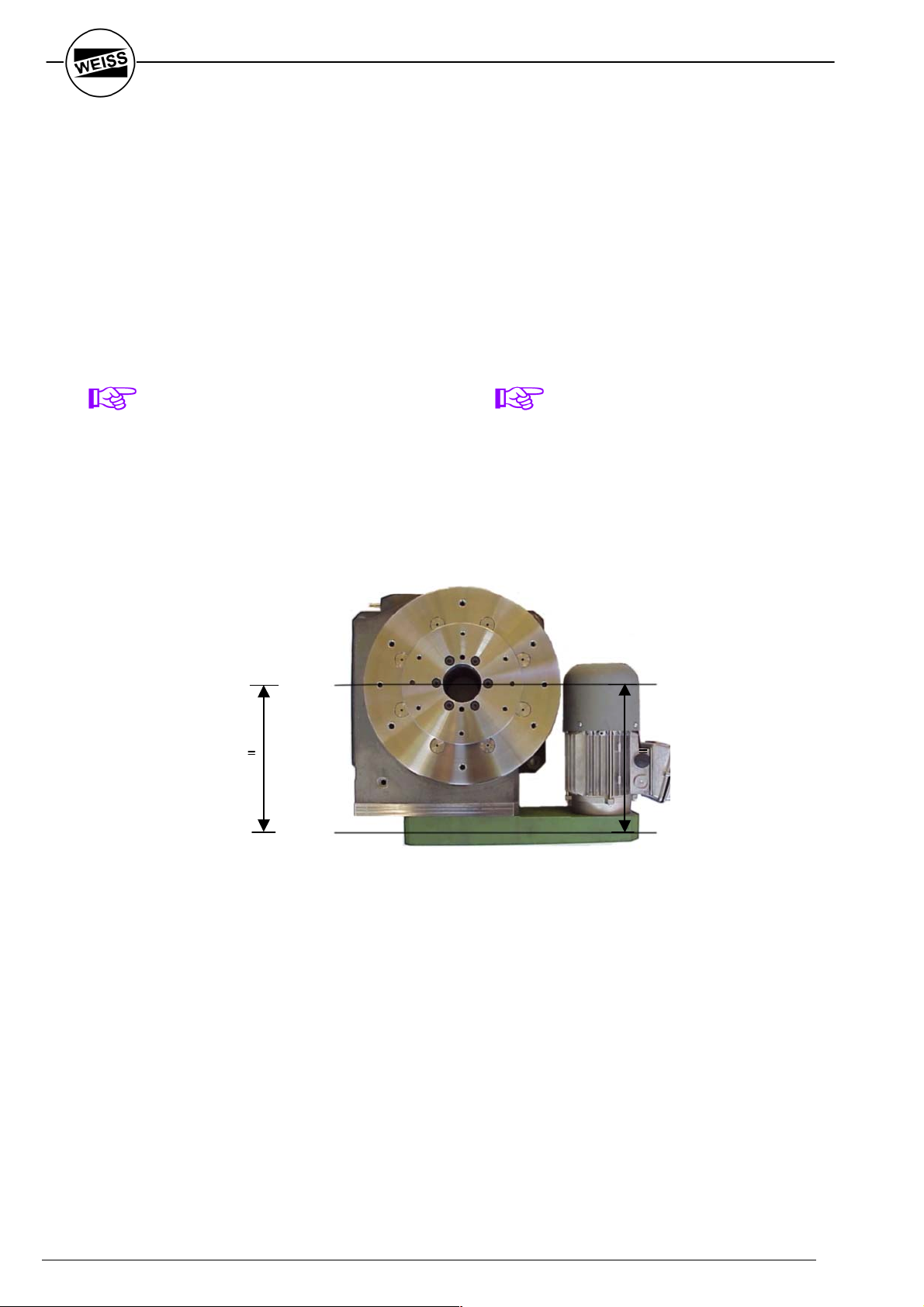
2.3 Einbaulagen der Rundschalttische und
Anbau des Motors (Antriebslage)
2.3 Mounting Postions of Indexers and
Drive Positions
Zulässige Einbaulagen
Allowed drive positions
normal über Kopf vertikal (Antrieb rechts) vertikal (Antrieb unten)
normal overhead vertical (drive at right) vertical (drive at
bottom)
Antriebslagen
Motor mounting positions
seitlich innen seitlich aussen unten innen unten aussen
lateral inside lateral outside bottom inside bottom outside
Fig. 2-2
Die aufgezeigten Möglichkeiten der
Antriebslagen sind für alle Einbaulagen der
Rundschalttische zulässig.
The shown possibilities of the drive positions
are acceptable for all mounting positions of
the index tables.
WEISS GmbH 03/2002 13

Die Lage des Motors kann nachträglich bei
jedem Rundschalttisch mit Ausnahme des
Typs TC 1000 (Bremsmotor im Gehäuse
eingebaut) durch Schwenken des Antriebsgehäuses um 90° geändert werden.
Bitte beachten Sie, dass die Lage der Entlüftungsbohrung nachträglich nicht mehr verändert werden kann. Bei den Tischen
TC 120G, TC 150T und TC 220T ist auf der
Unterseite eine zweite Entlüftungsbohrung
vorhanden. Bei Einbaulagen, abweichend von
der Bestellung, besteht die Möglichkeit, die
Entlüftungsschraube und den Verschlussstopfen zu tauschen. Bei allen anderen
Rundschalttischen muss die Einbaulage
schon bei der Bestellung bekannt sein.
The mounting position of the drive motor can
be rotated retroactively by 90° on every index
table with the exception of the model TC 1000
(the brake motor is integrated inside the
indexer housing).
Please note that the location of the breather
valve cannot be changed. The indexers
TC 120G, TC 150T and TC 220T have a
second breather bearing on the bottom. If the
indexer is installed in another mounting
position than ordered, there is the possibility
to change the breather valve and the plug. For
all other indexers the mounting position has to
be determined before purchase order
placement.
HINWEIS
Ein Rundschalttisch darf nie so eingebaut
oder gelagert werden, dass die Entlüftungsschraube nach unten gerichtet ist,
da sonst der Rundschalttisch Öl verlieren
kann!
HINWEIS
Ein Rundschalttisch darf nie so eingebaut
werden, dass das Gehäuse des
Zahnriemenantriebes nach oben gerichtet
ist, da sonst keine Schmierung gewährleistet ist!
Bemerkung:
Beim Einbau des Rundschalttisches ist auf
eine ausreichende Belüftung des
Antriebmotors zu achten.
Da der Antriebsmotor des TC 1000 im Rundtischgehäuse eingebaut und somit nicht
genug Luftvolumen zur Eigenkühlung
vorhanden ist, ist im seitlichen Abdeckblech
des Getriebegehäuses ein Fremdlüfter
eingebaut.
Elektrische Daten des Fremdlüfters:
230V / 50, 60 Hz (1 Phase); 0,075 A
Der Motor des Fremdlüfters muss über eine
Sicherung 0,1 A mittelflink angeschlossen
werden.
NOTE
Never install or store the indexer with the
breather valve located low. This
orientation will result in oil leaking from
the indexer!
NOTE
The index table shall never be installed
with the housing of the timing belt pointing
upwards. This would interrupt proper
lubrication.
Remark:
When mounting the index table please make
sure that the ventilation of the drive motor is
sufficient.
The model TC 1000 needs an additional
cooling fan for the drive motor, which is
installed inside the housing of the index table.
Electrical specifications for the cooling fan:
230VAC / 50, 60 Hz (single phase); 0.075 A
The motor for the cooling fan needs a 0.1 A
fuse.
14
WEISS GmbH 03/2002
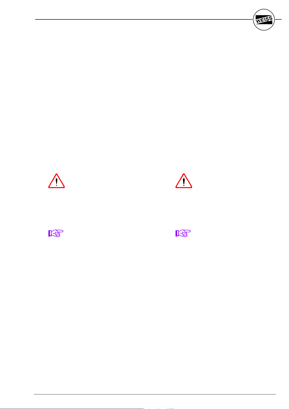
2.4 Positionsnocken/Näherungsinitiator
Die Rundschalttische sind mit einem
Positionsnocken (1) auf der Antriebskurve und
einem Näherungsinitiator "P" (2) ausgerüstet.
Der Positionsnocken ist je nach Typ des
Rundschalttisches formschlüssig mit der
Antriebskurve verschraubt (Gewindestift; Fig.
2-3) oder direkt angefräst (Fig. 2-4).
Aufgeschraubter Positionsnocken
(z.B. am TC 220):
2.4 Cam and Limit Switch
The index tables have an additional cam (1)
which is part of the barrel cam and a limit
switch “P” (2).
Dependant on the model the cam is either
bolted (setscrew; Fig.2-3) or directly milled on
to the barrel cam (Fig.2-4).
Boltet on cam
(i.e. TC 220)
1
2
Fig. 2-3
Angefräster Positionsnocken
(z.B. am TC 320):
Fig. 2-4
Milled on cam
(i.e. TC 320)
1
2
WEISS GmbH 03/2002 15

Der Näherungsinitiator dient zur Abfrage des
Positionsnockens, wobei induktive
Näherungsinitiatoren M12x1, PNP-Schließer,
10-30V DC für nichtbündigen Einbau
eingesetzt werden.
Ist der Näherungsinitiator aktiv, steht der
Rundschalttisch sicher verriegelt in einer der
möglichen Positionen. Es wird die Meldung
"Tisch in Position" ausgegeben (= Meldung
"P"). Die Steuerung kann jetzt die Bearbeitungsstationen freigeben.
Der Näherungsinitiator ist von aussen in das
Rundschalttischgehäuse eingeschraubt. Der
Schaltabstand beträgt ca. 2 mm und ist bei
abgenommenem Deckblech einstellbar (für
die Einstellung des Initiators siehe Kapitel
5.5).
2.5 Dauermagnetbremse
Es werden Drehstromnormmotoren mit
Zweiflächenbremse für Trockenlauf
eingesetzt.
Der Bremsdruck wird von Federn erzeugt. Die
Bremse wird elektromagnetisch gelöst
(24VDC ± 10%) und schließt sich beim
Ausschalten der Spannung (oder bei
Netzausfall) über Federkraft automatisch.
Im Jahresrhythmus oder alle 2 Millionen
Schaltungen muss der Luftspalt der Bremse
nachgestellt werden (siehe Kapitel 5.1).
Bei den Typen TC 120 und TC 150
(Ausführung ohne selbstnachstellende
Bremse) ist eine Bremse eingesetzt, die nicht
nachgestellt werden kann. Bei Verschleiß
muss die komplette Bremse ersetzt werden
(Vorgehen siehe Kapitel 6.6).
Bremsmotoren der Fa. KOBOLD haben eine
selbstnachstellende Bremse und dürfen nicht
nachgestellt werden. Die Lebensdauer dieser
Bremse liegt bei ca. 50 Millionen
Schaltspielen.
The limit switch monitors the position of the
barrel cam via a sensor cam.
We use a limit switch M12x1, PNP-Closed,
10-30 VDC.
The limit switch is active if the dial plate is in
one of the locked dwell positions. It will send
the message “dial plate in position”
(=message “P”). The PLC can now start the
assembly operations.
The limit switch is screwed into the index table
housing from the outside. The gap between
the limit switch and the cam is approx. 2 mm.
For adjustments the cover has to be taken off.
(See chapter 5.5)
2.5 Magnetic Brake
The 3-phase motors use a dual-surface nonlubricated brake.
The brake is activated by springs. It is
released electro magnetically (24VDC ± 10%)
and will be activated automatically by the
spring force if the power is turned off or in
case of a power failure.
The air gap of the brake has to be adjusted
once a year or after 2 million cycles (see
chapter 5.1)
Models TC 120 and TC 150 (version without
selfadjusting brake) use a brake that cannot
be adjusted. The complete brake has to be
replaced (see chapter 6.6)
The KOBOLD brake motor uses the selfadjusting brake that shall not be adjusted. It
can handle approx. 50 million brake cycles
before it has to be replaced.
16
WEISS GmbH 03/2002

2.6 Verändern der Schaltzeit
In Abhängigkeit vom Massenträgheitsmoment
und der Teilung ergibt sich eine "kürzest
mögliche Schaltzeit", die auf keinen Fall unterschritten werden darf (vgl.
Belastungsdiagramme in den Verkaufsunterlagen). Sollte die Schaltzeit nachträglich
geändert werden müssen, gibt es
verschiedene Zahnriemenübersetzungen
sowie 4-, 6- und 8-polige Motoren, mit denen
die Schaltzeit in Stufen verändert werden
kann.
Bitte setzen Sie sich mit uns oder einer
unserer Vertretungen in Verbindung, wenn
Sie den Rundschalttisch in einem andern
Anwendungsfall einsetzen wollen. Wir werden
die passende Untersetzung bestimmen und
Ihnen dann die benötigten Teile zusenden.
Bei Austausch des Motors:
siehe Kapitel 5.3.
Bei Austausch des Zahnriemensatzes:
siehe Kapitel 5.4.
2.6 Change of Cycle Time
The moment of inertia and the number of
stops determine the “shortest possible index
time” which shall not be shortened under any
circumstances. (See load diagram in the
sales brochure). Should it become necessary
to modify the index time you can chose from
various timing belt transmission combinations
or use a 4-, 6- or 8-pole motor.
Please contact one of our representatives if
you plan to use the index table for a different
application. We will determine the correct
timing belt transmission and motor
combination and can ship the necessary
parts.
To exchange the motor see chapter 5.3
To exchange the timing belt / pulley
combination see chapter 5.4.
WEISS GmbH 03/2002 17

- Für Ihre Notizen -
- For your Notes -
18
WEISS GmbH 03/2002

3 Steuern der Rundschalt-
tische
Im Folgenden wird nur die Ansteuerung des
Antriebes mit Bremsmotor betrachtet. Der
Antrieb mit Kupplungs-Brems-Kombination
verhält sich völlig identisch. Anstelle des
Motorschützes wird dort die Kupplungsspule
ein- bzw. ausgeschaltet.
3.1 Allgemeine Funktionsweise
Um den Antriebsteller zu drehen, müssen der
Motorschütz und die Bremsspule
eingeschaltet werden; um den Teller zu
stoppen, müssen beide ausgeschaltet
werden. Sind Motorschütz und Bremsspule
ständig eingeschaltet, so kommt es zu einer
taktenden Bewegung am Antriebsteller
(Beschleunigen - Bremsen - Stehen -
Beschleunigen - Bremsen .....). Diese
Bewegung wird in diesem Fall jedoch nicht
durch den Motor, sondern durch das Getriebe
realisiert.
Um den Rundschalttisch sinnvoll zu takten
(von einer Verriegelungsphase zur nächsten)
müssen in Abhängigkeit des
Positionsnockens "P" der Motorschütz und die
Bremse geschaltet werden.
Die Meldung "P" erfolgt, sobald der
Schaltteller verriegelt ist ("Tisch in Position")
und steht während der gesamten
Verriegelungsphase an. Sie sollte als
Startsignal für die Bearbeitungseinheiten
verwendet werden.
Um den Rundschalttisch zeitoptimal zu takten,
darf der Antrieb erst am Ende der Verriegelungsphase gestoppt werden. Andernfalls
geht die Zeit, die der Antrieb benötigt, um die
Verriegelungsphase zu durchlaufen, pro Takt
als Totzeit verloren. Diese Stopverzögerung
(auf der Steuerkarte TS 002 E das Signal
“Stoppverzögerungszeit“) muss mit der SPS
realisiert werden. Die Stopverzögerungszeit
ist so einzustellen, dass der Antrieb erst am
Ende der Verriegelungsphase zum Stehen
kommt. Der Näherungsinitiator muss aber
noch sicher aktiv sein.
3 Control of the index table
This chapter describes the control of the drive
with brake motor. To drive the indexer with a
clutch-brake-combination, it is basically the
same with the exception that the controller
triggers the coil for the clutch instead of the
motor contactor.
3.1 Function in general.
In order to turn the dial plate the motor
contactor and the brake coil have to be
activated. To stop the rotation both have to
be switched off. If both-contactor and brake
coil- stay activated the dial plate will continue
to index (accelerate – decelerate – dwell –
accelerate – decelerate…). This movement is
realized by the barrel cam and gears and not
by the motor.
In order to index the dial plate correctly from
dwell position to dwell position it is necessary
that the motor contactor and motor brake are
being activated by the cam and limit switch
“P”.
The message “P” is activated as soon as the
dial plate is in the locked position stays on
during the whole dwell period (“Table in
Position”). This signal should be used as start
signal for the assembly steps.
To shorten and optimize the cycle time the
motor shall be stopped at the end of the dwell
period. The time for the barrel cam to go
through the dwell period after each index is
“unproductive”. With your PLC or the Control
Card TS 002E you can adjust the “Stop Delay
Time” to ensure that the drive stops exactly at
the end of the dwell period.
But the limit switch still has to be
activated.
Linkslauf Rechtslauf Pendeln
CCW rotation CW rotation Reciprocating
Fig. 3-1
WEISS GmbH 03/2002 19

3.2 Steuern mit der Steuerkarte TS 002 E
3.2 Control with the Controller Card TS 002 E
Fig. 3-2
Die Rundschalttische sind mit einem
Positionsnocken auf der Antriebskurve und
einem Näherungsinitiator "Tisch in Position“
(“P") ausgerüstet. Die Meldung "P" erfolgt,
sobald sich der Tisch in verriegelter Position
befindet. Daraufhin meldet die Steuerkarte die
Freigabe an die Bearbeitungsstationen (vgl.
auch Kapitel 2.4).
Fig. 3-3
Das Abschalten des Bremsmotors erfolgt
nach Ablauf der in Stufen einstellbaren
Stopverzögerungszeit. Dadurch dreht der
Antrieb in eine ideale Startposition für den
neuen Zyklus.
Der Antrieb muss innerhalb der
Verriegelungsphase zum Stillstand kommen.
Dies wird von der Steuerkarte überwacht. Im
Fehlerfall wird eine Störung nach außen
gemeldet ("Position überfahren").
Fig. 3-2
The index tables have an additional cam
attached to the end of the main barrel cam.
This cam will be sensed by a proximity switch
to indicate “Table in Position” (“P”). The
message “P” is sent as soon as the dial is in
locked position. The control card sends a
signal to start the next assembly steps. (See
chapter 2.4)
The drive motor will be switched off after
going through the programmable stop delays.
This will position the drive motor into an ideal
start position for the next index. The control
card makes sure that the drive motor will stop
within the dwell period. There will be a fault
message (“Position Overrun”) if the indexer
the overruns the lock position.
20
WEISS GmbH 03/2002

HINWEIS
Tritt der Fehler "Position überfahren" auf,
müssen sofort alle Bearbeitungsstationen
rückgesetzt werden, da der Rundschalttisch
nicht in der verriegelten Position steht
(Crashgefahr).
Tritt das Überfahren der Verriegelungsposition
nach längerer Betriebszeit immer häufiger auf,
ist dies in der Regel ein Hinweis darauf, dass
die Bremse nachgestellt werden muss
(siehe Kapitel 5.1) oder der Motorschütz (bei
Bremsmotoren) verschlissen ist.
Durch Schlüsselschalter umschaltbar sind drei
Betriebsarten möglich:
1. Automatik Betrieb nur durch parallele
E/A-Schnittstelle
2. Schritt Betrieb nur von Hand
durch START- oder STOPTaste an der Steuerkarte
TS 002 E
3. Bremse lösen Antriebsteller ist von Hand
drehbar, solange er nicht
in Verriegelung steht
NOTE
If the fault message “Position overrun” is
displayed all assembly stations have to be
freed immediately from any assembly tooling
because the dial will not be in a locked
position (danger of crash).
If the overrun of the locked position happens
more frequently its an indication that the
brake has to be adjusted (see chapter 5.1)
or that the motor contactor (brake motors) has
worn out.
There are three operational modes, which can
be selected by key position:
1. Automatic Operation via parallel I/O
interface
2. Inching Manual operation via Start-
(Step Mode) or Stop button on Control
card TS 002 E
3. Brake release Tooling plate can be
rotated manually as long
as it is not in locked
position
WARNUNG
Es ist in keinem Fall möglich, den Rundschalttisch von Hand in eine der
möglichen Verriegelungspositionen zu
drehen!
Für weitergehende Informationen konsultieren
Sie bitte die Betriebsanleitung für die
elektronische Steuerkarte TS 002 E.
WARNING
It is not possible to rotate the dial plate
into one of the locked positions!
For additional information please consult the
Manual for the electronic Control Card
TS 002 E.
WEISS GmbH 03/2002 21

3.3 Steuern mit der Steuerung
EF-xxx
3.3 Controlling with the
Controller Card EF-xxx
Fig. 3-4
Bei Einsatz der EF-Steuerung wird der
Drehstrommotor über einen Frequenzumformer angesteuert. Durch die Möglichkeit,
eine Stopprampe vorzugeben, wird die
Bremse erst bei der Drehzahl n=0 geschaltet.
Hierdurch wird ein Verschleiß der Bremse
vermieden.
Die SPS verwaltet drei Parametersätze:
Parametersatz 1 und 2 stehen zur freien
Verfügung, Parametersatz 3 dient zum
Anfahren nach NOTAUS Situationen.
Mit einem aufsteckbaren Keypad werden die
notwendigen Einstellungen und Optimierungen vorgenommen. Eventuell auftretende
Fehler werden in der Klartextanzeige
dargestellt. Es stehen sieben Sprachen zur
Verfügung.
Bei der Erstinbetriebnahme fragt die
Steuerung nach dem Tischtyp (z.B. TC 500).
Hiermit werden Default-Parameter geladen,
mit denen sofort gestartet werden kann.
Anschließend ist die Stopprampe zu optimieren bis der Positionsnocken auf der Antriebskurve kurz vor dem Ende der Verriegelungsphase steht. Somit ist eine zeitoptimale Startposition erreicht.
On implementing of the EF controller the
three-phase motor is controlled by a
frequency inverter. By using a stop ramp
braking takes place at a speed of n=0. This
means no wear will occur to the motor brake.
The PLC organises three parameters:
Parameters 1 and 2 are freely disposable,
parameter 3 is used for moving out of an
e-stop situation.
The removable keypad will require fitting to
enable the necessary setting and optimising
to be carried out. Faults are displayed in plain
language. Seven different languages can be
selected.
When installed the controller will ask for the
indexer type (e.g. TC 500). In this way default
parameters are loaded and the machine can
be run immediately. Consequently the stop
ramp can be optimised so that the barrel cam
stops close before the end of the dwell phase.
The best possible starting position is
guaranteed in this way.
Fig. 3-5
22
WEISS GmbH 03/2002

Die übergeordnete Steuerung gibt eine
steigende Flanke auf den Eingang "Start
Flanke" (I11) und wartet bis die Rückmeldung
"Tisch in Position" (O7) kommt. Die SPS
unterscheidet dabei automatisch, ob der
Parametersatz 3 (Start aus Zwischenposition)
oder der Kunden-Parametersatz (1 bzw. 2)
geladen wird.
The main controlling system gives a rising
signal at the input "start edge" (I11) and waits
until "indexer in position" (O7) reports back.
The PLC distinguishes automatically if
parameter 3 (starting from an in-between
position) or the customer parameter (1 or 2)
should be loaded.
HINWEIS
Tritt der Fehler "Position überfahren" auf,
müssen sofort alle Bearbeitungsstationen
rückgesetzt werden, da der Rundschalttisch
nicht in der verriegelten Position steht
(Crashgefahr).
Durch die Codestelle W10 (im Keypad)
anwählbar sind folgende Betriebsarten
möglich:
1. Automatik Betrieb nur durch digitale
E/A's möglich
2. Hand Betrieb nur von Hand
durch START- oder STOPTaste am Keypad möglich
3. Bremse lösen Antriebsteller ist von Hand
drehbar, solange er nicht
in Verriegelung steht
NOTE
If the fault message “Position overrun” is
displayed, assembly stations have to be reset
back into the locked position (danger of
crash).
There are operational modes, which can be
selected by code position W10 (on the
keypad):
1. Automatic Operation via digital I/O
interface only
2. Manual Manual operation via Start-
or Stop button on keypad
3. Brake release Tooling plate can be
rotated manually providing
it is not in its locked
position
WARNUNG
Es ist in keinem Fall möglich, den Rundschalttisch von Hand in eine der
möglichen Verriegelungspositionen zu
drehen!
Für weitergehende Informationen konsultieren
Sie bitte die Betriebsanleitung für die
Rundtischsteuerungen EF-xxx.
WARNING
It is not possible to rotate the dial plate in
any one of the locked positions!
For additional information please consult the
Operation Manual for the Frequency
Inverter EF-xxx.
WEISS GmbH 03/2002 23

3.4 Steuerungsablauf mit Fremdsteuerung
(SPS)
0. Ausgangsstellung ist ideale Startposition
Motorschütz: AUS
Bremse: AUS
„P“ aktiv
Ü Teller steht in verriegelter Position
1. Zyklusstart durch SPS
Motorschütz: AUS
Bremse: EIN
„P“ aktiv
Ü Bremse öffnet, Antriebskurve und Teller
stehen noch
2. Ca. 20 ms später
Motorschütz: EIN
Bremse: EIN
„P“ nicht aktiv
Ü Teller dreht
3. Beginn der Verriegelung
Motorschütz: EIN
Bremse: EIN
„P“ aktiv
Ü Antriebskurve dreht noch, Teller steht
schon
Freigabe der Bearbeitung, Starten der
Stoppverzögerungszeit
4. Nach Ablauf der Stoppverzögerungszeit
Motorschütz: AUS
Bremse: AUS
„P“ aktiv
Ü Antriebskurve steht, Teller steht
3.4 Control Sequence with PLC
0. Home position is the ideal start position
Motor contactor: OFF
Break: OFF
“P“ Active
Ü Dial plate in locked position
1. Cycle start through PLC
Motor contactor: OFF
Brake: ON
“P”: Active
Ü Brake opens, cam and dial do not rotate
yet
2. Approx. 20 msec later
Motor contactor: ON
Brake: ON
“P”: Not active
Ü Dial rotates
3. Start of dwell period
Motor contactor: ON
Brake: ON
“P”: active
Ü Cam still rotates, dial locked already
Start signal for assembly steps
Start of stop delay timer
4. After stop delay time
Motor contactor: OFF
Brake: OFF
“P”: Active
Ü Cam stopped, dial locked
24
WEISS GmbH 03/2002

HINWEISE
Nach Schritt 4 muss der Näherungsinitiator
"P" ständig abgefragt werden. Sollte "P"
inaktiv werden, ohne dass die SPS einen
neuen Zyklus gestartet hat ("Position
überfahren"), müssen sofort alle
Bearbeitungsstationen rückgesetzt werden,
da der Rundschalttisch nicht in der
verriegelten Position steht (Crashgefahr).
Tritt das Überfahren der Verriegelungsposition
nach längerer Betriebszeit immer häufiger auf,
ist dies in der Regel ein Hinweis darauf, dass
die Bremse nachgestellt werden muss
(siehe Kapitel 5.1) oder der Motorschütz (bei
Bremsmotoren) verschlissen ist.
NOTES
After step 4 the limit switch has to be scanned
constantly. Should “P” become inactive
without a new cycle start from the PLC
(“Position overrun”) all assembly tools have to
be retracted immediately because the dial
plate is not in a locked position. (Danger of
crash).
If the overrun of the locked position happens
more frequently its an indication that the
brake has to be adjusted (see chapter 5.1)
or that the motor contactor (brake motors) has
worn out.
WEISS GmbH 03/2002 25
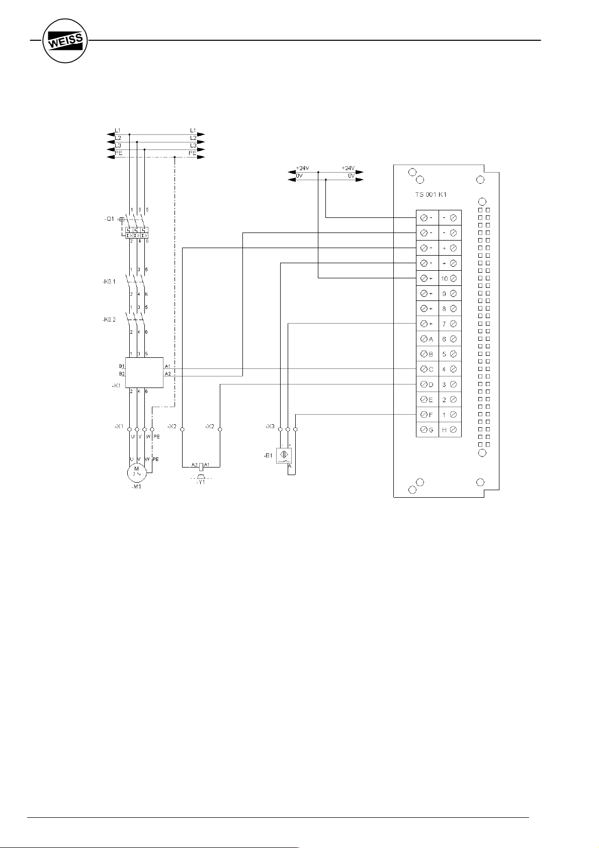
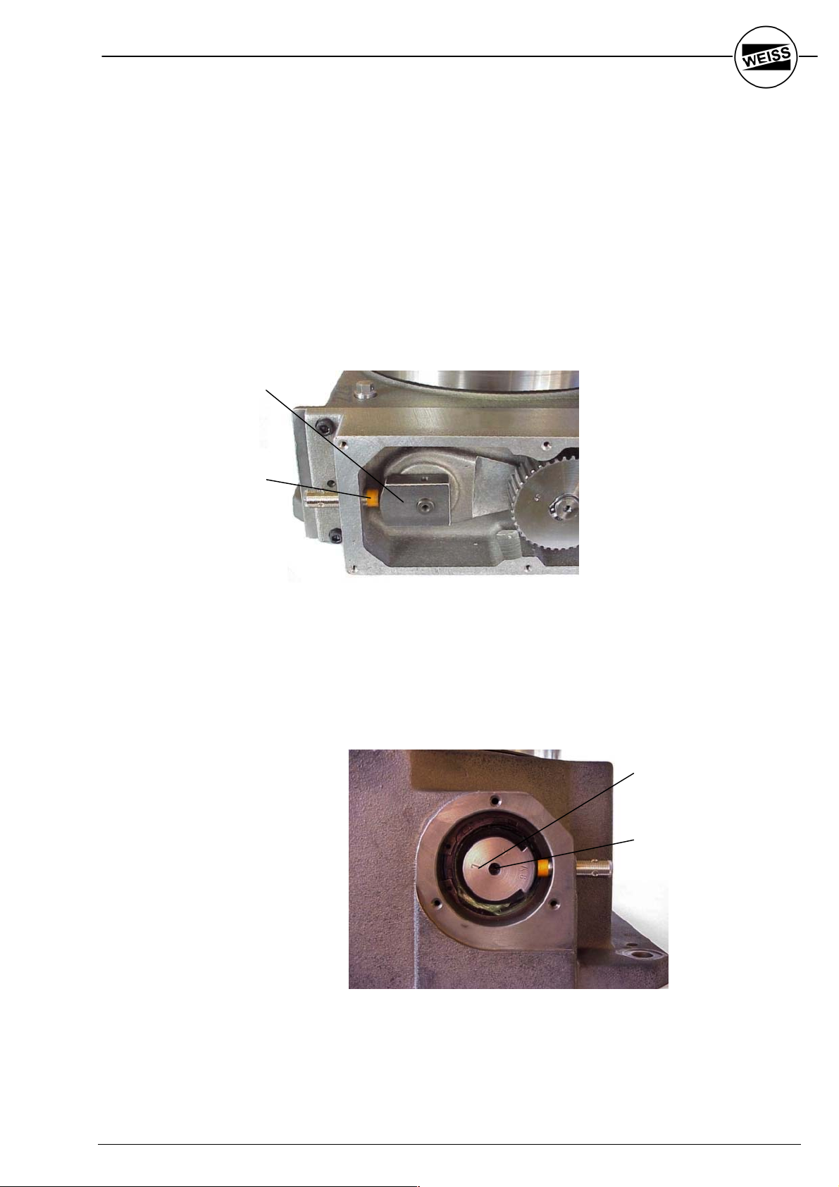
3.5 Anschluss von Steuerung,
Motor und Bremse
3.5 Control, Drive Motor and Brake Wiring
Bremsmotor Normalbetrieb (24 V Bremse)
Brake Motor Normal Operation
(24 V Brake):
Fig. 3-6
Q1: Motorschutzschalter
K0.1, K0.2: Notausrelais
K1: Elektronischer Motorschütz
M1: Rundschalttischmotor
Y1: Bremse
B1: Initiator Position
Q1: Protective motor switch
K0.1, K0.2: E-STOP Relay
K1: Electronic Motor Contactor
M1: Index Table Motor
Y1: Brake
B1: Limit Switch Position
26
WEISS GmbH 03/2002

Bremsmotor Pendelbetrieb (24 V Bremse)
Reciprocating Operation (24 V Brake)
Fig. 3-7
Q1: Motorschutzschalter
K0.1, K0.2: Notausrelais
K1: Elektronischer Wendeschütz
M1: Rundschalttischmotor
Y1: Bremse
B1: Initiator Position
HINWEIS
Beim Anschließen der selbstnachstellenden
Bremse (Motorfabrikat KOBOLD) muss
unbedingt auf die richtige Polung der beiden
Bremsanschlüsse geachtet werden. Die
Polarität der Bremsanschlüsse ist im
Motorklemmbrett aufgedruckt.
Q1: Protective motor switch
K0.1, K0.2: E-STOP Relay
K1: Electronic Motor Contactor
M1: Index Table Motor
Y1: Brake
B1: Limit Switch Position
NOTE
Please pay attention to the correct polarity
when wiring the 2 connections of the selfadjusting magnetic brake (KOBOLD motor).
The polarity of the brake connections is
printed in the terminal box of the motor.
WEISS GmbH 03/2002 27

HINWEISE
Sollte eine 230V-Wechselstrombremse
(Gleichrichter im Klemmenkasten des Motors)
zum Einsatz kommen, so sind folgende
Besonderheiten zu beachten:
Durch das Ausschalten der Motorinduktivität
entsteht eine Gegenspannung, die kurzzeitig
die Bremse noch offenhält, obwohl der Motor
schon abgeschaltet wurde.
Es ist deshalb bei schnelllaufenden
Rundschalttischen notwendig, den
Bremsstromkreis durch einen zusätzlichen
Kontakt am Motorschütz zu öffnen (siehe Fig.
3-6 und 3-7).
Bei Einsatz der 230V-Wechselstrombremse
ist die Ansteuerung des Motors über einen
Frequenzumrichter nicht möglich!
NOTES
If you use a 230 VAC brake (rectifier located
in the terminal box of the drive motor) you
need to know the following:
Although the motor is turned off its inductivity
generates a counter voltage, which keeps the
brake activated for an additional short
moment.
For fast indexing applications it therefore
becomes necessary to open the brake circuit
through an additional contact of the motor
contactor (see Fig. 3-6 and 3-7).
If you use a 230VAC brake it's not possible to
operate the motor with a frequency inverter!
28
WEISS GmbH 03/2002
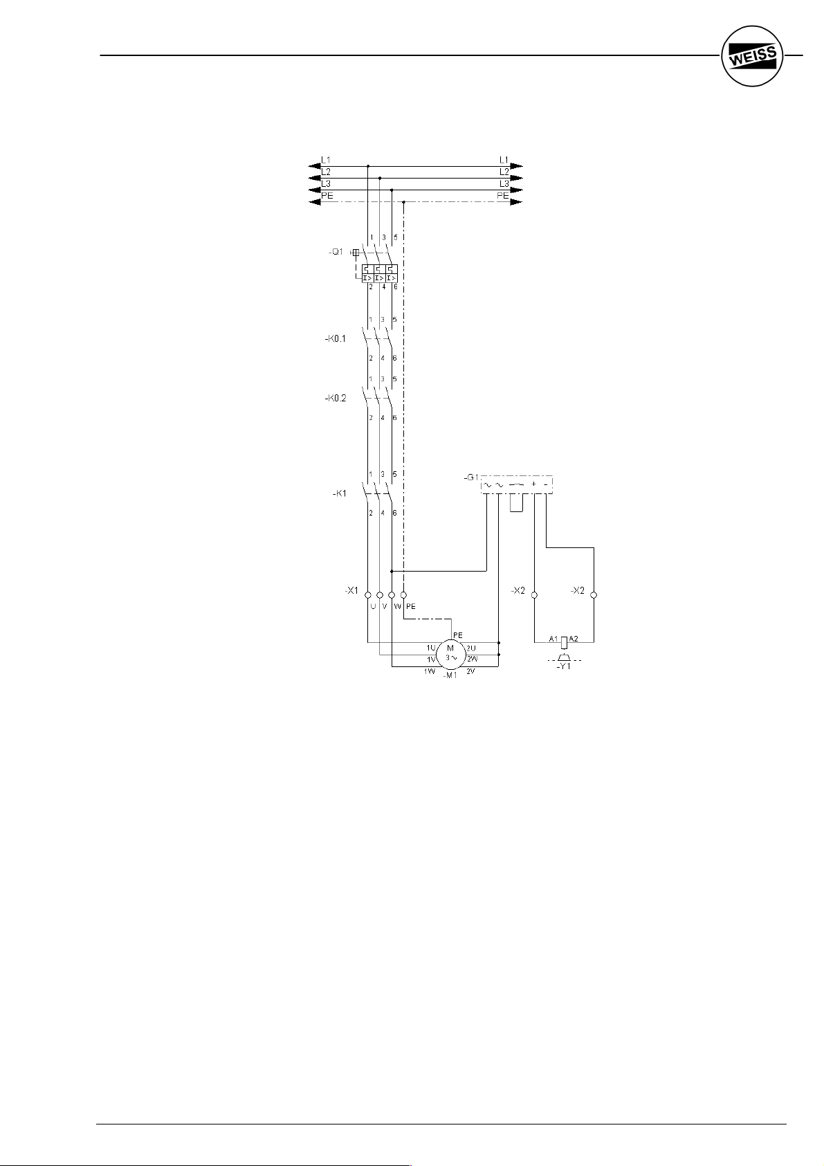
Schaltungsbeispiel für langsamlaufende
Rundschalttische
Example for slow cycling indexing tables
Fig. 3-8
Q1: Motorschutzschalter
K0.1, K0.2: Notausrelais
K1: Motorschütz
M1: Rundschalttischmotor
Y1: Bremse
G1: Bremsgleichrichter
Q1: Protective motor switch
K0.1, K0.2: E-STOP Relay
K1: Motor Contactor
M1: Index Table Motor
Y1: Brake
G1: Rectifier for brake circuit
WEISS GmbH 03/2002 29

Schaltungsbeispiel für schnelllaufende
Rundschalttische
Example for fast cycling indexing tables
Fig. 3-9
Q1: Motorschutzschalter
K0.1, K0.2: Notausrelais
K1: Motorschütz
M1: Rundschalttischmotor
Y1: Bremse
G1: Bremsgleichrichter
Welche der beiden Varianten für Ihren Rundschalttisch gewählt wurde, entnehmen Sie
bitte der Auftragsbestätigung, dem
Lieferschein oder der Rechnung.
Q1: Protective motor switch
K0.1, K0.2: E-STOP Relay
K1: Motor Contactor
M1: Index Table Motor
Y1: Brake
G1: Rectifier for brake circuit
You can find the option, which was used, for
your application on the order confirmation, on
the shipping papers or on the invoice.
30
WEISS GmbH 03/2002

Anschluss der Steuerung EF 037/1
(Einphasige Ausführung)
Wiring of Controller Card EF 037/1
(single-phase version)
Fig. 3-10
A1: SPS
A2: Frequenzumformer
A3: CAN-Repeater
F1: Sicherung
L1: Ferrite
K0.1, K0.2: Notausrelais
M1: Rundschalttisch-Motor
(Dreieckschaltung!)
Y1: Bremse
B1: Initiator Position
Eingänge:
I4: Fehler zurücksetzen
I5: Parametersatz 2
I6: Parametersatz 3
ignorieren
I8: Mode 2
I9: /RESET
I10: Positi onssens or
I11: Start (F lanke)
I12: Start (P egel)
I13: Drehrichtung
(CW / CCW)
Ausgänge:
O1: Summe Störung
O2: Position überfahren
O3: Überlast
O5: Automatik
O6: Start zulässig
O7: Tisch in Position
A1: PLC
A2: Frequency inverter
A3: CAN-Repeater
F1: Fuse
L1: Ferrite
K0.1, K0.2: E-STOP ralay
M1: Indexer Motor
(delta-connected!)
Y1: Brake
B1: Limit Switch Position
Inputs:
I4: Reset error
I5: Parameter set 2
I6: Ignore
parameter set 3
I8: Mode 2
I9: /RESET
I10: Limit s witch P osition
I11: Start ( edge)
I12: Start (l evel)
I13: Direction of rot ation
(CW / CCW)
Outputs:
O1: Sum of faults
O2: Position overrun
O3: motor overload
O5: Automatic
O6: start ready
O7: indexer in Position
WEISS GmbH 03/2002 31

Anschluss der Steuerungen
EF 150/3, EF 220/3, EF 300/3
(Dreiphasige Ausführung)
Wiring of Controller Cards
EF 150/3, EF 220/3, EF 300/3
(three-phase version)
Fig. 3-11
A1: SPS
A2: Frequenzumformer
A3: CAN-Repeater
F1: Sicherung
L1: Ferrite
K0.1, K0.2: Notausrelais
M1: Rundschalttisch-Motor
(Sternschaltung!)
Y1: Bremse
B1: Initiator Position
R1: Bremswiderstand
Eingänge:
I4: Fehler zurücksetzen
I5: Parametersatz 2
I6: Parametersatz 3
ignorieren
I8: Mode 2
I9: /RESET
I10: Positi onssens or
I11: Start (F lanke)
I12: Start (P egel)
I13: Drehrichtung
(CW / CCW)
Ausgänge:
O1: Summe Störung
O2: Position überfahren
O3: Überlast
O5: Automatik
O6: Start zulässig
O7: Tisch in Position
A1: PLC
A2: Frequency inverter
A3: CAN-Repeater
F1: Fuse
L1: Ferrite
K0.1, K0.2: E-STOP ralay
M1: Indexer Motor
(star-connected!)
Y1: Brake
B1: Limit Switch Position
R1: Brake resistor
Inputs:
I4: Reset error
I5: Parameter set 2
I6: Ignore
parameter set 3
I8: Mode 2
I9: /RESET
I10: Limit switch P osition
I11: Start ( edge)
I12: Start (l evel)
I13: Direction of rot ation
(CW / CCW)
Outputs:
O1: Sum of faults
O2: Position overrun
O3: motor overload
O5: Automatic
O6: start ready
O7: indexer in Position
32
WEISS GmbH 03/2002

4 Inbetriebnahme
4.1 Sicherheitsbestimmungen
WARNUNG
Transportieren Sie den Rundschalttisch nur
mit einem Hebezeug, welches für das entsprechende Gewicht ausgelegt ist (siehe
nachfolgende Gewichtstabelle).
Verwenden Sie für das Befestigen des
Rundschalttisches am Hebezeug Ringschrauben, die der Belastung gemäss
nachstehender Gewichtstabelle sicher
standhalten.
Für TC 120 bis TC 320 genügen zwei Ringschrauben (Fig. 4-1), ab TC 500 sind drei
Ringschrauben einzusetzen.
Befestigen Sie die Ringschrauben in den
Gewinden des Drehtellers.
4 Start-Up
4.1 Safety Regulations
WARNING
For transportation use only hoists which are
designed for the weight of the indexer. (See
the following weight table).
Use eyebolts, which are strong enough in
accordance with this weight table.
Use 2 eyebolts for indexer models TC 120 to
TC 320 (see Fig. 4.1), use 3 eye bolts for
models TC 500 and above.
The dial plates have the correct tapped holes
for the eyebolts.
Fig. 4-1
Gewichte der Rundschalttische:
Typ / Type Gewicht / Weight [kg]
TC 120 20
TC 150 25
TC 220 42
TC 320 120
TC 500 270
TC 700 470
TC 1000 1300
WEISS GmbH 03/2002 33
Weight of the index tables

WARNUNG
l Arbeiten an der elektrischen Installation
dürfen nur von einer Elektrofachkraft
oder von unterwiesenen Personen unter
Leitung und Aufsicht einer
Elektrofachkraft ausgeführt werden.
l Stellen Sie sicher, dass die
Einspeisungskabel beim Anschliessen
nicht unter Spannung stehen.
l Befolgen Sie die fachspezifischen Sicher-
heitsvorschriften.
l Zuleitungen (Querschnitt und
Absicherung) nach Schema und örtlichen
Vorschriften erstellen.
4.2 Elektrische Vorbereitungen
Dem Antriebsmotor des Rundschalttisches
sind in jedem Fall
r geeignete NOT-AUS-Einrichtungen
nach EN 60 204-1
(Einrichtungen für Handlungen im
Notfall)
r ein Motorschütz sowie
r ein Motorschutzschalter
vorzuschalten.
Im NOT-AUS-Betrieb muss die
Motorspannung unterbrochen werden.
Die 24V-DC-Versorgungsspannung der
Steuerkarte braucht dagegen nicht unterbrochen zu werden. In diesem Falle muss jedoch
der RESET/STOP-Eingang der Steuerkarte
deaktiviert werden (Klemme 2: low-Pegel), um
erstens die Bremse zu schließen und
zweitens die zwangsläufig auftretende
Fehlermeldung "Motorüberlast" zu unterdrücken, falls die Motorspannungsabschaltung mitten im Zyklus erfolgt.
WARNING
l Only electricians or trained persons
under supervision of an electrician should
work on the electrical installation.
l Make sure that the power cables are not
live while being connected to the table.
l Follow the safety rules and regulations of
the specific industry.
l Power supply cables should adhere to
the local specifications.
4.2 Electrical preparations
The following devices must be connected in
series with the drive motor of the index table:
r E-STOP according to EN 60 204-1
r Motor contactor
r Protective motor switch
In E-STOP the power has to be interrupted.
The 24VDC power for the control card does
not have to be interrupted. In this case the
RESET/STOP input of the control card has to
be deactivated (Connection 2, low level) to
activate the motor brake and to avoid the fault
message “Overload” in case the E-stop
occurs during the index period.
34
WEISS GmbH 03/2002

4.3 Entlüftungsschraube/Verschlussstopfen
Die Entlüftungsschraube muss sich immer im
oberen Teil des Gussgehäuses befinden.
Beim Einsatz des Rundschalttisches gemäss
den Bestellangaben ist die Entlüftungsschraube bereits am richtigen Ort plaziert.
4.3 Breather Valve / Plug
The breather valve always has to be on the
upper part of the indexer housing. If the
application of the indexer is in accordance
with the specifications of the purchase order
the breather valve will be located in the
correct area.
HINWEIS
Vor Inbetriebnahme den Verschlussstopfen
(1) der Entlüftungsschraube entfernen.
1
Fig. 4-2
Wenn die Einbaulage gegenüber den Bestellangaben geändert wird, ist die Entlüftungsschraube gegebenenfalls neu zu plazieren.
Sie muss sich immer im oberen Teil des
Gussgehäuses befinden.
Bei den Rundschalttischen TC 120G,
TC 150T und TC 220T ist hierzu auf der
Unterseite eine zweite Entlüftungsbohrung
vorhanden. Entlüftungsschraube und
Verschlussstopfen können dann getauscht
werden.
NOTE
Before start-up the plug (1) has to be removed
from the valve.
In cases were the original mounting position
of the indexer has to be changed, the breather
may need to be relocated to the top half of the
indexer.
Therefore the indexers TC 120G, TC 150T
and TC 220T have a second breather bearing
on the bottom. If the indexer is installed in
another mounting position than ordered, there
is the possibility to change the breather valve
and the plug.
WEISS GmbH 03/2002 35
4.4 Allgemeines Vorgehen zur Inbetriebnahme
1. Verschlussstopfen der
Entlüftungsschraube entfernen (siehe
Kapitel 4.3).
2. Den Rundschalttisch durch Verstiften und
Verschrauben auf seinem Unterbau befestigen. Die Positionen der hierzu vorgesehenen Stift- und Gewindelöcher sind den
Verkaufsunterlagen zu entnehmen.
3. Elektrische Anschlüsse vornehmen
(Sicherheitsbestimmungen beachten!).
4. Probelauf durchführen.
4.4 General Start-Up
1. Remove plug from breather valve.
2. Install the indexer with dowel pins and
bolts on to the machine surface. Locations
of dowel pin holes and bolt holes are
shown in the brochures.
3. Make electrical connections (Follow safety
instructions)
4. Perform a test run.
HINWEIS
Bei Anlieferung steht der Rundtischteller
immer in der ersten der möglichen
Verriegelungspositionen (die Achse der
Stiftlöcher im Rundtischteller liegt parallel zur
Zahnriemenachse; vgl. Fig. 4-3).
Fig. 4-3
4.5 Montage von Zusatzschalttellern
Aus Genauigkeitsgründen (Rundlauf und
Teilgenauigkeit) bitte den Zusatzschaltteller
immer nur mit den dafür vorgesehenen
Passbohrungen und Gewinden fixieren. Den
eventuell vorhandenen Zentrierbund nicht für
die Tellerbefestigung nutzen; deshalb die
Mittenbohrung des Zusatzschalttellers ca. 1
mm grösser wählen als der Zentrierbund am
stehenden Mittelteil des Rundschalttisches.
Beim Verstiften des Zusatzschalttellers die
Stifte an der Einführseite leicht abpolieren und
gleichmässig mit kleinem Hammer
einschlagen, um Genauigkeitsverluste zu
vermeiden.
NOTE
At the time of delivery the dial plate is always
in the first dwell position (the center line of the
dowel pin holes is parallel to the timing belt,
see Fig.4-3)
4.5 Installation of Tooling Plate
For reasons of accuracy (run out and
repeatability) please use only the existing
dowel pin holes and threaded bolt holes to fix
the tooling plate. Don’t use the centering
shoulder to fix the tooling plate. For this
reason make the diameter of the center hole
of the tooling plate 1 mm larger than the
centering shoulder of the fixed center plate of
the indexer. The dowel pins should be
chamfered slightly before installation of the
tooling plate. Use a light hammer to avoid
loss of accuracy.
36
WEISS GmbH 03/2002

5 Wartung
5.1 Einstellung der Bremse bei Bremsmotoren
HINWEISE
Bremsmotoren der Fa. KOBOLD haben eine
selbstnachstellende Bremse und dürfen nicht
nachgestellt werden.
Die Rundschalttische der Typen TC 120 und
TC 150 sind mit Bremsmotoren ausgerüstet,
deren Bremse nicht nachstellbar ist. Bei
Verschleiß muss die komplette Bremse
ersetzt werden (siehe Kapitel 6.6).
Im Jahresrhythmus oder alle 2 Millionen
Schaltungen muss der Luftspalt der Bremse
bei allen anderen Bremsmotortypen nachgestellt werden. Die Bremse befindet sich
zwischen Lüfterrad und Lagerschild des
Bremsmotors.
Vorgehen:
5 Maintenance
5.1 Adjusting the brake of braking motors
NOTES
The brake motors of KOBOLD make, have a
self-adjusting brake, which cannot be
adjusted.
The index tables Model TC 120 and TC 150
have brake motors with a brake, which cannot
be adjusted. The complete brake has to be
exchanged (See chapter 6.6).
The air gap of all the other brake motors has
to be adjusted once a year or after 2 million
cycles,. which ever comes first. The brake is
located between the plate and the fan.
How to proceed:
WARNUNG
Motor spannungslos schalten und vor Wieder-
inbetriebsetzung durch Drittpersonen sichern!
1. Motor spannungslos schalten.
2. Lüfterkappe entfernen.
3. Lüfterrad innen am Kunststoffbund mit
zwei Montierhebeln abheben
(siehe Fig. 5-1).
WARNING
Disconnect motor from power and secure it
against a restart!
1. Disconnect motor from power
2. Remove fan cowl
3. Lift off fan wheel with tools as shown in
Fig. 5-1
Fig. 5-1
WEISS GmbH 03/2002 37

4. Den Luftspalt X mit Hilfe einer
Fühlerlehre durch Verdrehen der
Einstellstücke (1) auf 0,2 – 0,3 mm am
gesamten Umfang der Bremsscheibe
einstellen.
5. Lüfterrad und Lüfterkappe wieder mon-
4. Use a test gauge while adjusting the air
gap (0.2 - 0.3 mm) around the
circumference of the brake disk by
turning the adjuster screws (1).
5. Install the fan wheel and the fan cowl.
tieren.
NOTE
HINWEIS
Zum Verdrehen der Einstellstücke (2) die Be-
festigungsschrauben (1) lösen, zum Messen
des Luftspaltes Befestigungsschrauben anziehen!
To turn the adjuster screws (2) you have to
loosen the bolts (1), to check the air gap you
have to tighten the bolts.
1
Fig. 5-2
Fig. 5-3
2
X
0,2 – 0,3 mm
38
WEISS GmbH 03/2002

5.2 Bremse ersetzen
Die Bremse der Motoren für die Rundschalttische der Typen TC 120 und TC 150 kann
nicht nachgestellt werden. Bei Verschleiß ist
deshalb die komplette Bremse gemäss
nachstehendem Vorgehen zu ersetzen.
Nach dem gleichen Vorgehen sind auch die
Bremsen der Motoren der anderen
Rundschalttischtypen zu ersetzen, wenn
diese nicht mehr nachgestellt werden können.
Bei Motoren mit selbstnachstellender Bremse
(KOBOLD) muss der gesamte Motor
getauscht werden.
5.2 Replace Brake
The brake on the TC 120 and TC 150 index
tables cannot be adjusted. After it is worn
out, it has to be replaced completely as
described in this section.
If the brakes on indexers TC 220 onwards
cannot be adjusted any more, they too have
to be exchanged in the same way.
The self-adjusting brake on the KOBOLD
motors cannot be replaced. In this case the
complete motor has to be exchanged.
WARNUNG
Motor spannungslos schalten und vor Wieder-
inbetriebsetzung durch Drittpersonen sichern!
Vorgehen:
1. Motor spannungslos schalten.
2. Lüfterkappe entfernen.
3. Lüfterrad innen am Kunststoffbund mit
zwei Montierhebeln abheben
(vgl. Fig. 5-4).
WARNING
Disconnect the power from the motor.
How to proceed:
1. Disconnect motor from power
2. Remove fan cowl
3. Lift off fan wheel with tools as shown in
Fig. 5-4
Fig. 5-4
WEISS GmbH 03/2002 39

4. Befestigungsschrauben (1) entfernen.
5. Nabe (2) (Mitnehmer) und Bremsscheibe
(3) ersetzen.
4. Remove bolts (1).
5. Replace hub (2) and brake disk (3).
1
2
Fig. 5-5
6. Bremse einstellen
(Vorgehen siehe Kapitel 5.1).
7. Lüfterrad und Lüfterkappe wieder montieren.
5.3 Motor ersetzen
HINWEIS ZUM TC 1000
Der Motor des TC 1000 ist im
Getriebegehäuse eingebaut. Hier muss
zusätzlich das seitliche Abdeckblech des TC
1000 entfernt werden. Der Austausch des
Motors erfolgt dann ebenfalls gemäss
nachstehendem Vorgehen.
3
6. Adjust brake
(see Chapter 5.1)
7. Reinstall fan wheel and fan cowl
5.3 Replace motor
NOTE REGARDING TC 1000
The motor of the TC 1000 is installed inside
the housing. The side cover will need to be
removed. The rest of the procedure is the
same as described in this chapter.
WARNUNG
Motor spannungslos schalten und vor Wieder-
inbetriebsetzung durch Drittpersonen sichern!
Vorgehen:
1. Motor spannungslos schalten.
2. Motor und Bremse abklemmen.
3. Abdeckblech des Zahnriemenkastens
Disconnect the power from the motor.
How to proceed:
1. Disconnect motor from power.
2. Disconnect motor and brake.
3. Remove timing belt cover.
WARNING
entfernen.
40
WEISS GmbH 03/2002

4. Vier Flanschschrauben (1) des Motors
lösen und den Motor aus dem
Rundschalttisch entfernen.
4. Remove the 4 bolts (1) of the motor and
remove the motor from the index table.
Fig. 5-6
5. Zahnriemenscheibe vom alten Motor
lösen, dazu:
· Abdeckscheibe entfernen (Schraube
(2) lösen)
· Zahnriemenscheibe mit geeignetem
Abzieher von der Motorwelle abziehen (Bordscheibe nicht beschädigen!).
6. Zahnriemenscheibe auf neuen Motor
montieren.
7. Neuen Motor anflanschen.
8. Zahnriemen spannen (siehe Kapitel 5.4).
9. Motor und Bremse anklemmen.
10. Probelauf durchführen.
11. Zahnriemenspannung erneut prüfen
(siehe Kapitel 5.4).
12. Abdeckblech des Zahnriemenkastens
anschrauben.
1
2
5. Remove pulley from old motor as follows:
· Remove screw (2) and cover
· Remove pulley from shaft with
appropriate puller
6. Install pulley on new motor.
7. Install new motor.
8. Tension the timing belt (Chapter 5.4)
9. Rewire motor and brake
10. Test run.
11. Re-check tension of timing belt.
(Chapter 5.4)
12. Install timing belt cover.
WEISS GmbH 03/2002 41

5.4 Zahnriemen ersetzen
5.4 Replace Timing Belt
WARNUNG
Motor spannungslos schalten und vor Wieder-
inbetriebsetzung durch Drittpersonen sichern!
1. Abdeckblech entfernen.
2. Vier Flanschschrauben (1) des Motors
lösen.
Fig. 5-7
WARNING
Disconnect the power to the motor
1. Remove cover.
2. 2. Loosen the 4 motor bolts (1)
1
3. Zahnriemen tauschen.
4. Motor wieder anflanschen.
HINWEIS ZUR ZAHNRIEMEN-
SPANNUNG
Der Zahnriemen ist dann richtig gespannt,
wenn er sich in der Mitte von Hand leicht um
45° bis 90° (je nach Riemenlänge) anstellen
lässt.
3. Exchange timing belt
4. Slide motor into correct position and
tighten bolts
CORRECT TIMING BELT TENSION
The timing belt will be correctly tensioned if
you can twist the belt by approx. 45° to 90° (in
the middle between the 2 pulleys).
Fig. 5-8
42
WEISS GmbH 03/2002

5.5 Näherungsinitiator ersetzen
1. Abdeckblech entfernen.
5.5 Replace Limit Switch
1. Remove cover.
2. Sicherstellen, dass sich der Positionsnocken beim Näherungsinitiator befindet.
Wenn nötig durch Verschieben des
Zahnriemens den Nocken korrekt
positionieren (nur möglich, wenn Bremse
gelöst ist, d.h. wenn 24V-Spannung
angelegt ist).
3. Defekten Näherungsinitiator aus dem
Gehäuse herausschrauben.
4. Neuen Initiator bis auf Anschlag
einschrauben.
5. Abstand zwischen Initiator und Positionsnocken wie folgt einstellen:
Näherungsinitiator um 2 Umdrehungen
zurückschrauben.
6. Initiator mit Kontermutter sichern.
7. Abdeckblech anbringen.
5.6 Schmierstoffe
Das Rundschalttischgetriebe ist wartungsfrei.
Es läuft im Ölbad, damit ist die Lebensdauerschmierung sichergestellt.
Verwendetes Öl:
Shell Omala 680. Kennzeichnung nach
DIN 51517, CLP 680.
Füllmengen (für Typenreihe TC-X):
Die Füllmenge hängt vom Typ des
Rundschalttisches sowie teilweise von dessen
Einbaulage und Getriebestufe ab:
2. Make sure the cam is close to the limit
switch. If necessary bring the cam into
the correct position by moving the timing
belt. (This is only possible if the brake is
released by energizing it with 24 V DC).
3. Remove the defect limit switch.
4. Install new limit switch; screw it in to the
end.
5. Adjust the gap between the cam and limit
switch as follows: Retract the limit switch
by 2 full turns.
6. Lock limit switch with counter nut.
7. Install cover.
5.6 Lubrication
The barrel cam and cam followers of the index
table are maintenance free. They run in oil,
which guarantees lifetime lubrication.
Oil used:
Shell Omala 680. Identification according to
DIN 51517, CLP 680.
Quantities (only for types TC-X):
The quantity depends on the indexer model,
its mounting position and gear ratio:
Typ / Type Menge / Quantity
(Type T)
Menge / Quantity
(Type X)
TC 120 150 ml 200 ml
TC 150 150 ml 250 ml
TC 220 300 ml 300 ml
TC 320 1,5 l 1 l
TC 500 7 l 4 l
TC 700 11 l 10 l
TC 1000 15 l 16 l
WEISS GmbH 03/2002 43

- Für Ihre Notizen -
- For your Notes -
44
WEISS GmbH 03/2002

6 Störungsbehebung
6.1 Störungsbehebung bei der
Rundschalttischsteuerung TS 002 E
Mit der Steuerkarte TS 002 E haben Sie ein
Hilfsmittel zur Hand, mit dem Sie die Mehrzahl
der auftretenden Fehler selbst analysieren
und größtenteils selbst beheben können.
Fehleranzeige "Position überfahren"
Es ist sehr wichtig festzustellen, bei welcher
Nockenposition die Fehlermeldung ausgegeben wurde! Folgende Fälle sind zu unterscheiden:
A: Der Nocken steht noch auf dem
Näherungsinitiator.
B: Die Nockenstellung entspricht dem
größten Teil der Drehphase.
C: Der Nocken hat den Näherungsinitiator
gerade verlassen.
A: Ursache: Der Näherungsinitiator ist
defekt
Maßnahme: Näherungsinitiator
ersetzen (siehe Kapitel
5.5)
Ursache: Die Kabelverbindungen
zum Näherungsinitiator
haben Wackelkontakt
Maßnahme: Verkabelung überprüfen,
defekte Kabel ersetzen
Ursache: Der Abstand zwischen
Nocken und Näherungsinitiator ist zu groß
(Nennabstand 2 mm!)
Maßnahme: Nennabstand korrekt ein-
stellen (siehe Kapitel 5.5)
B: Ursache: Kurze Störspitzen am
Eingang "F" der
Steuerkarte (Nachweis
durch Speicheroszilloskop)
Maßnahme: Initiatorkabel räumlich
anders verlegen oder
abschirmen
6 Troubleshooting
6.1 Troubleshooting Control Card TS 002 E
The control cards TS 002 E will help you to
analyse and rectify most of the faults, which
can occur.
Fault Message “Position Overrun”
It is important to know the position of the cam
attached to the end of the main barrel cam,
when a fault signal has been triggered! We
distinguish between 3 scenarios:
A: The cam is still positioned on the limit
switch.
B: The position of the cam has moved off
the limit switch and represents the major
part of the index phase.
C: The cam has moved just off the limit
switch.
A: Cause: The limit switch is defect
To rectify: Exchange limit switch
(Chapter 5.5)
Cause: Loose cable connection to
the limit switch
To rectify: Check or replace wiring
Cause: Distance between cam
and limit switch too big
(nominal distance 2 mm)
To rectify: Adjust to nominal distance
(Chapter 5.5)
B: Cause: Short voltage peak at input
“F” of the control card
(check with oscilloscope)
To rectify: Re-route limit switch wiring
or use shielded cabling
WEISS GmbH 03/2002 45

C: Ursache: Schützkontakte stark
abgebrannt oder verklebt
Maßnahme: Schütz ersetzen (am
besten durch
Halbleiterrelais)
Ursache: Bremsscheibe abgenutzt,
Luftspalt zu groß
Maßnahme: Bremsscheibe ggf.
erneuern, Luftspalt neu
einstellen (0,2 – 0,3 mm)
Fehleranzeige "Motor Überlast"
Dieser Fehler tritt auf, wenn ca. 8 – 9 s nach
einem Startsignal keine Fertigmeldung vom
Rundtischdrehen eintrifft.
1: Ursache: Fehlende Motorspannung
Maßnahme: Spannung messen,
Sicherungen und Motorschutzschalter überprüfen,
ggf. ersetzen
2: Ursache: NOT-AUS-Situation
während des Rundtischdrehens, ohne dass die
Steuerkarte vom Not-Stop
Information bekommt
(Klemme 2)
Maßnahme: NOT-AUS-Situation muss
an Klemme 2 angeschlossen werden
3: Ursache: Rundschalttisch dreht
schwer oder ist blockiert,
vermutlich wegen Verschmutzung zwischen
zusätzlich aufgebautem
Drehteller und stehender
Mittelplatte oder Spannscheibe
Maßnahme: Mittelplatte und Drehteller
abnehmen, reinigen und
Rundtisch ohne Platten
einem Testlauf
unterziehen
4: Ursache: Zahnriemen defekt
Maßnahme: Zahnriemen auf Bruch
überprüfen,
gegebenenfalls ersetzen
(siehe Kapitel 5.4)
C: Cause: Contacts of contactor
burned or sticking together
To rectify: Replace contactor (best to
use semi conductor)
Cause: Brake worn out, air gap too
big
To rectify: If necessary replace brake
disk, adjust air gap (0.2 -
0.3 mm)
Fault Message “Motor Overload”
If the indexer rotation finish signal is not
received 8 – 9 sec after the start signal, fault
message “Motor Overload” will be displayed.
1: Cause: No motor power
To rectify: Check power, fuses and
protective motor switch
and replace if necessary
2: Cause: E-Stop but the control card
did not get signal of E-stop
(Terminal clamp 2)
To rectify: E-Stop has to be wired to
clamp 2
3: Cause: Tooling plate has
difficulties to index or is
jammed (possibly dirt
between tooling plate and
fixed center plate)
To rectify: Remove center plate and
tooling plate, clean them
and index the indexer w/o
these two plates
4: Cause: Defect timing belt
To rectify: Check and possibly
replace timing belt
(Chapter 5.4)
46
WEISS GmbH 03/2002

Fehleranzeige "Kurzschluss"
1: Ursache: Einer der mit Buchstaben
bezeichneten Ausgänge
der Steuerkarte wird
statisch oder dynamisch
mit mehr als 2 A belastet
Maßnahme: Anschlüsse der
Steuerkarte sind auf
größere Stromstärken zu
untersuchen
2: Ursache: Einer der mit Ziffern
bezeichneten Ausgänge
der Steuerkarte wird
statisch oder dynamisch
mit mehr als 200 mA
belastet
Maßnahme: Anschlüsse der
Steuerkarte sind auf
größere Stromstärken zu
untersuchen
3: Ursache: Auf Leitungen der Versor-
gungsspannung (+24 V
oder GND) treten
Spannungsspitzen auf
Maßnahme: Spannungen messen,
Gründe für Überspannung
eruieren und für Abhilfe
sorgen
4: Ursache: Versorgungsspannung
höher als 30 V (auch kurzzeitig)
Maßnahme: Spannung messen,
Gründe für höhere
Fault Message “Electrical Short”
1: Cause: The static or dynamic load
on one of the controller
card out-puts, which is
identified by a letter, is
more than 2 A
To rectify: Check the connection of
the controller card for
Excessive load
2: Cause: The static or dynamic load
on one of the controller
card out-puts, which is
identified by a number, is
more than 200 mA
To rectify: Check the connection of
the controller card for
Excessive load
3: Cause: There are voltage spikes
on the wiring for the power
supply (+24V or GND)
To rectify: Check the voltages, find
and eliminate reasons for
the spikes
4: Cause: Voltage of power supply
higher than 30 V (for short
period)
To rectify: Check the voltages, find
and eliminate reasons for
the spikes
Spannung eruieren und für
Abhilfe sorgen
WEISS GmbH 03/2002 47

6.2 Störungsbehebung bei der
Rundschalttischsteuerung EF xxx
Bei der Rundschalttischsteuerung EF xxx wird
im Keypad neben der Fehlernummer auch die
Fehlermeldung als Klartext angezeigt.
6.2 Troubleshooting the Control Card EF xxx
The control card EF xxx shows errors as error
number and error message at the keypad.
Störungsmeldungen
Nr. / no. Text Beschreibung Description
1 Motorüberlast
(Timeout Drehen)
Motor Overload
2 Endlagenschalter
überfahren
Overrun Prox Switch
3 Start nicht zulässig
(Automatik-Betrieb)
Start not permissible
(automatic operation)
4 Start nicht zulässig
(Hand-Betrieb)
Start not permissible
(manual operation)
5 Endlagenschalter fällt
ab
Prox switch no signal
Umin Bremse
6
Umin Brake
1000 Fehler Frequenz-
umrichter
Error Frequency
Inverter
Nach dem Start des Motors erreicht der Tisch
nicht innerhalb der vorgegebenen Maximalzeit
seine Endposition. Mögliche Ursachen:
- Tisch ist mech. blockiert/dreht zu schwer
- Sensor falsch eingestellt
- Sensorsignal unterbrochen
Nach dem Befehl Motor STOP wird
Endlagenschalter überfahren. Mögliche
Ursachen:
- Nachlaufzeit zu lang eingestellt
- Stop-Rampe zu lang eingestellt
Im Betriebsmode AUTOMATIK wurde ein
Startbefehl erkannt, der aber nicht ausgeführt
werden kann. Mögliche Ursachen:
- Input 9 (/RESET /STOP) auf LOW
- Es steht eine Störmeldung an, trotzdem
wurde ein Startbefehl
gegeben
Im Betriebsmode HAND wurde ein Startbefehl
erkannt, der aber nicht ausgeführt werden
kann
Tisch steht in Position, und Signal von
Endlagenschalter hat HIGH->LOW Flanke
Mindestspannung Bremse unterschritten Brake voltage is below minimum.
Es liegt eine Störung im Frequenzumrichter
vor.
Error Messages
Indexer does not make prox switch within preprogrammed max time. Possible reasons:
- tooling plate too heavy or mechanically
blocked
- misadjustment of prox switch
- prox switch signal interrupted
Prox switch was over-run after motor STOP
signal was activated.
Possible reasons:
-Stop delay programmed too long.
- Stop slope programmed too long.
A start signal was recognized in AUTOMATIC,
which can not be executed. Possible reasons:
- Input 9 (/RESET /STOP) on LOW
- A start command was given although an
error message was received
A start signal was recognized in MANUAL,
which can not be executed.
Index table in dwell and signal of prox switch is
on HIGH->LOW slope.
Frequenc y Inverter has a fault.
Rücksetzen von Störungsmeldungen
Zum Zurücksetzen von Störungsmeldungen
gibt es folgende Möglichkeiten:
r STOP-Taste am Keypad drücken
r Eingang I4 der SPS auf HIGH setzen
r Eingang I9 der SPS auf LOW setzen (nur
bei Konfiguration über W012)
48
WEISS GmbH 03/2002
Reset of error messages
There are the following choices to reset error
messages:
r press the STOP-key on the keypad
r set input I4 of the PLC to HIGH
r set input I9 of the PLC to LOW (only if
configures via W012)

7 Ersatzteile
Als Anhang zu den Lieferpapieren für Ihren
Rundschalttisch finden Sie eine Liste der
Verschleißteile des ausgelieferten Modells.
Diese Liste ist ebenfalls der vorliegenden
Betriebsanleitung beigefügt.
Um Missverständnissen beim Bestellen von
Ersatzteilen vorzubeugen, bitten wir Sie, in
Ihren Ersatzteil-Bestellungen immer folgende
Daten anzugeben:
r Seriennummer gemäss WEISS-
Typenschild am Rundschalttisch
r Bestellnummer des Ersatzteils gemäss
Verschleißteilliste
r Anzahl Ersatzteile
Ihre Ersatzteil-Bestellung senden Sie bitte an:
7 Spare Parts
Together with the shipping papers you will find
a list of the wear parts for the specific model
ordered.
To avoid any misunderstanding with your
spare parts order, we would require the
following information:
r Serial Number of the index table from the
WEISS type plate
r Part numbers from the wear parts list
r Quantity of spare parts
Please send your spare parts order to:
WEISS GmbH
Sondermaschinentechnik
Siemensstraße 17
D-74722 Buchen/Odw.
Tel.: +49 (0) 6281 / 5208-0
Fax: +49 (0) 6281 / 9150
eMail: service@weiss-gmbh.de
Internet: http://www.weiss-gmbh.de
Im Internet können Sie sämtliche Vertreteradressen abrufen.
You will find all addresses of our
representatives on our web page.
WEISS GmbH 03/2002 49

- Für Ihre Notizen -
- For your Notes -
50
WEISS GmbH 03/2002

8 Entsorgung und Recycling
Ein nicht mehr verwendbarer Rundschalttisch
darf nicht als ganze Einheit entsorgt werden.
WARNUNG
Das im Rundschalttisch enthaltene Öl ist vor
der Zerlegung des Rundschalttisches
abzulassen und einer autorisierten
Ölsammelstelle zur umweltgerechten
Entsorgung zuzuführen.
Der Rundschalttisch ist anschließend zu
zerlegen. Die Einzelteile sind nach Art der
Materialien zu recyklen. Nicht wiederverwendbare Materialien artgerecht
entsorgen!
Auskünfte über Entsorgungs- und
Sammelstellen erteilen Ihnen Ihre lokalen
Verwaltungsbehörden.
Bei der Entsorgung müssen auf jeden Fall die
einschlägigen landesüblichen und regionalen
Gesetze und Richtlinien beachtet werden.
8 Disposal and Recycling
A redunant index table should not be
disposed of, as a complete unit.
WARNING
The oil in the index table has to be collected
and submitted to an authorized recycler.
The index table has to be dismantled and the
different materials should be recycled
accordingly.
If in doubt please contact your local
authorities.
In all cases you should adhere to the
respective laws.
WEISS GmbH 03/2002 51

- Für Ihre Notizen -
- For your Notes -
52
Weiss GmbH 03/2002

A Anhang
A.1 Zusatzinformationen
Ringrundschalttische TR und NR
Ebenheit der Auflagefläche
Die Ebenheit des Maschinengestells hat
direkte Auswirkungen auf die Rund- und Planlauftoleranzen des Ringrundschalttisches.
Transport
WARNUNG
Transportieren Sie den Ringrundschalttisch
nur mit einem Hebezeug, welches für das
entsprechende Gewicht ausgelegt ist (siehe
nachfolgende Gewichtstabelle).
Verwenden Sie für das Befestigen des Ringrundschalttisches am Hebezeug Ringschrauben, die der Belastung gemäss
nachstehender Gewichtstabelle sicher
standhalten.
Verwenden Sie bitte die 3 mitgelieferten
Ringschrauben. Entfernen Sie die Verschlussstopfen und befestigen Sie die Ringschrauben
in den Gewinden des Aluminiumtellers.
Gewichte der Ringrundschalttische:
A Appendix
A.1 Additional information
Indexing Rings TR and NR
Flatness of the bearing area
The flatness of the base mounting plate has a
direct effect on the tolerances of run-out and
plane-parallelism of the indexing ring.
Transportation
WARNING
For transportation use only hoists which
have the capacity to lift the weight of the
indexing ring. (See the following weight
table).
Use eyebolts, which are strong enough in
accordance with this weight table.
Use 3 eyebolts for the indexing ring (included
in delivery). Remove the plugs and assemble
eyebolts into threads on the aluminium ring.
Weight of the indexing rings:
Typ / Type Gewicht / Weight [kg]
TR 1100 A 480
TR 1500 A 680
TR 2200 A 950
Einbaulage
Die Ringrundschalttische TR und NR können
ausschließlich in der Einbaulage NORMAL
(siehe Kapitel 2.3) eingesetzt werden, d.h.
waagerecht!
Mounting Position
The Indexing Rings TR and NR only can be
mounted in the NORMAL horizontal position
(refer to chapter 2.3)!
WEISS GmbH 03/2002 53

Verstiften des Ringrundschalttisches
A Zwei Passbohrungen dienen zum Verstif-
ten des Gussringes auf der Grundplatte.
B Sollten aus baulichen Gründen die
Passungen „A“ nicht benutzt werden
können, so nutzen Sie bitte die Bohrungen
„B“ als Zentrierung, bohren den Guss
gemeinsam mit der Grundplatte ab und
reiben die Löcher zum Verstiften auf.
Pinning the indexing ring
A Two fit bores for pinning the cast iron ring
onto the base plate.
B If for design reasons it is not possible to
use the fit bores "A", centring location
holes "B" can be used. Drill through the
cast iron and base plate and ream prior to
pinning.
54
Weiss GmbH 03/2002

Ersetzen des Näherungsschalters
r Näherungsschalterbuchse (A) inkl.
Näherungsschalter demontieren
Replacement of the limit switch
r Remove limit switch fixture incl. limit switch
(A)
Fig. A-2
r Näherungsschalter ausschrauben
(Schalter für nichtbündigen Einbau
verwenden)
r Flächendichtungsmasse (z.B. Teroson
Fluid D Universal Dichtungsmasse) auf
das Gewinde des neuen Näherungsschalters auftragen, so dass im späteren
Betrieb kein Öl durch das Endschaltergewinde auslaufen kann
r Näherungsschalter soweit einschrauben,
dass dessen Kopf ca. 1 mm übersteht
(siehe Fig. A-3)
r remove limit switch (use limit switch type
not-flush mounting)
r Apply sealing compound (i.e. Teroson
Fluid D Universal) onto the limit switch
thread, to avoid oil leakage.
r Install new limit switch. Screw in until head
protrudes by approx. 1 mm (see Fig. A-3)
Fig. A-3
r Kabeldose waagerecht einstellen und mit
Mutter kontern
r Näherungsschalterbuchse wieder
montieren
r install cable socket horizontally and fix by
locknut
r reinstall limit switch fixture
WEISS GmbH 03/2002 55
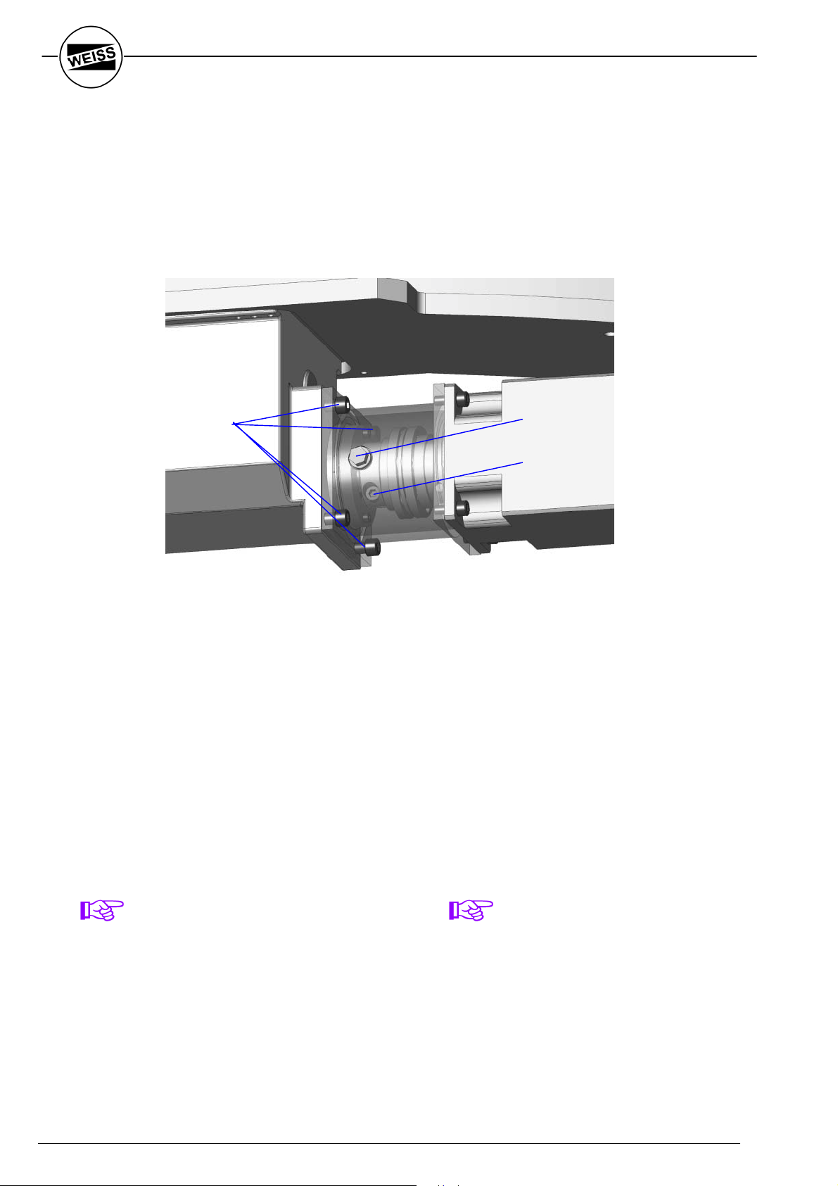
A.2 Zusatzinformationen
Ringrundschalttisch NR
A.1 Additional information
Rotary Indexing Ring NR
Einbau des Ringrundschalttisches NR
Zum Einbau des Ringrundschalttisches vom
Typ NR in den Montagedurchbruch der
Grundplatte (in Fig. A-4 nicht eingezeichnet)
ist der Motor inkl. der Kupplung zu
demontieren.
(C)
Mounting the Indexing Ring NR
When mounting the rotary indexing ring NR
through the assembly hole of the base plate
(not drawn in Fig. A-4) motor incl. coupling
has to be removed.
(A)
(B)
Fig. A-4
1. Verschlussstopfen (A) ausschrauben
2. durch die Öffnung hindurch die Klemmschraube (B) der Kupplung lösen
3. 4 Flanschschrauben (C) lösen
4. Motor inkl. Kupplung und Zwischenflansch
vom Antrieb abziehen
Nach Montage des Ringrundschalttisches auf
der Grundplatte kann der Antrieb wieder montiert werden.
HINWEIS ZUR
KUPPLUNGSKLEMMSCHRAUBE
Die Klemmschraube der Kupplung ist mit
einem Anzugsmoment von 80 Nm anzuziehen.
1. unscrew and remove plug (A)
2. loosen the clamp bolt (B), situated in hole
beneath plug (A)
3. remove 4 flange screws (C)
4. remove motor incl. coupling and additional
flange from drive.
After mounting the rotary indexing ring onto
the base-plate the drive can be reassembled
again.
NOTE FOR THE COUPLING CLAMP
BOLT
The torque of the coupling clamp bolt has to
be 80 Nm.
56
Weiss GmbH 03/2002

- Für Ihre Notizen -
- For your notes -
WEISS GmbH 03/2002 57

- Für Ihre Notizen -
- For your notes -
58
Weiss GmbH 03/2002

- Für Ihre Notizen -
- For your notes -
WEISS GmbH 03/2002 59

WEISS GmbH Sondermaschinentechnik
Siemensstrasse 17 D-74722 BUCHEN Tel.: +49 (0) 6281 / 5208-0 Fax: +49 (0) 6281 / 9150
eMail: info@weiss-gmbh.de Internet: http://www.weiss-gmbh.de
 Loading...