

Page 1
Weiss Engineering Ltd.
Florastrasse 42, 8610 Uster, Switzerland
www.weiss-highend.com
MEDEA+
OWNERS MANUAL
Page 2

OWNERS MANUAL FOR WEISS MEDEA+ D/A CONVERTER
Page: 2 Date: 02/11 /dw
INTRODUCTION
D
ear Customer
Congratulations on your purchase of the MEDEA+ D/A Converter and welcome to the family of
Weiss equipment owners!
The MEDEA+ is the result of an intensive research and development process. Research was
conducted both in analog and digital circuit design, as well as in signal processing algorithm
specification.
On the following pages I will introduce you to our views on high quality audio processing. These
include fundamental digital and analog audio concepts and the MEDEA+ converter.
I wish you a long-lasting relationship with your MEDEA+.
Yours sincerely,
Daniel Weiss
President, Weiss Engineering Ltd.
Page 3

OWNERS MANUAL FOR WEISS MEDEA+ D/A CONVERTER
Page: 3 Date: 02/11 /dw
TABLE OF CONTENTS
4 A short history of Weiss Engineering
5 Our mission and product philosophy
6 Advanced digital and analog audio concepts explained
6 Jitter Suppression, Clocking
8 Upsampling, Oversampling and Sampling Rate Conversion in General
11 Reconstruction Filters
11 Analog Output Stages
12 Dithering
14 The MEDEA+ D/A Converter
14 Features
17 Operation
20 Technical Data
23 Contact
24 Addendum for the FireWire option
32 Addendum for the ST Glass Fiber input option
Page 4

OWNERS MANUAL FOR WEISS MEDEA+ D/A CONVERTER
Page: 4 Date: 02/11 /dw
Page 5

OWNERS MANUAL FOR WEISS MEDEA+ D/A CONVERTER
Page: 5 Date: 02/11 /dw
A SHORT HISTORY OF WEISS ENGINEERING
After studying electrical engineering, Daniel Weiss joined the Willi Studer (Studer - Revox)
company in Switzerland. His work included the design of a sampling frequency converter and of
digital signal processing electronics for digital audio recorders.
In 1985, Mr. Weiss founded the company Weiss Engineering Ltd. From the outset the company
concentrated on the design and manufacture of digital audio equipment for mastering studios. Its
first product was the modular "102 Series" system. After 23 years, this system is still up to date
(24 bit / 96kHz) and is still being sold. Hundreds of Mastering Studios around the world use it
every day.
In the early nineties the „Gambit Series“ was launched, taking ergonomics and sonic quality to new
heights. The „Gambit Series“consists of stand-alone units like Equalizer, Denoiser / Declicker,
Dynamics Processor, A/D converter, D/A converter, Sampling Frequency Converter, Dithering etc.
40 bit floating point processors and sampling rates up to 96kHz are employed.
In 2001 we have decided to enter the High-End Hi-Fi market which offers a comparable clientele
to that of the Mastering Studios. Both consist of critical and discerning listeners, who are in
constant search for the best audio reproduction equipment or the best audio tools respectively.
Our list of clients includes big names, like SONY, BMG, EMI, Warner, Hit Factory, Abbey Road,
Teldec, Telarc, Unitel, Gateway Mastering (Bob Ludwig), Bernie Grundman Mastering, Masterdisk,
Sterling Sound, Whitfield Street, Metropolis and hundreds more.
For a more comprehensive list you are invited to visit our pro audio website at www.weiss.ch.
Page 6

OWNERS MANUAL FOR WEISS MEDEA+ D/A CONVERTER
Page: 6 Date: 02/11 /dw
OUR MISSION AND PRODUCT PHILOSOPHY
The wealth of experience we have gained in over 20 years of designing products for top Mastering
Engineers, we now apply to the design of outstanding High-End Hi-Fi products.
Our mission is to create equipment which becomes classic right from the outset; - outstanding in
sonics and design.
These are some of the milestones at Weiss Engineering:
1985 Introduction of the "102 Series", a 24 bit modular digital audio processor for Mastering
Studios
1986 Introduction of one of the first sample rate converters for digital audio
1987 Introduction of one of the first digital equalizers
1989 Introduction of one of the first digital dynamics processors
1991 Introduction of the "Ibis" digital mixing console, built for the mix-down of classical music
1993 Introduction of the "Gambit" Series of digital audio processors, which employ 40 bit floating
point processing and sport an extremely ergonomic user interface
1995 First 96kHz sampling rate capable products delivered
2001 Introduction of the MEDEA, our High-End Hi-Fi D/A converter and the first product in our
High-End Series
2004 Introduction of the JASON CD Transport
2007 Introduction of the CASTOR, our High-End Hi-Fi Power Amplifier
2008 Introduction of the MINERVA Firewire DAC, VESTA Firewire Interface, ATT202 passive
attenuator
2010 Introduction of the DAC202 DAC, INT202 Firewire Interface, MEDEA+ DAC
Page 7

OWNERS MANUAL FOR WEISS MEDEA+ D/A CONVERTER
Page: 7 Date: 02/11 /dw
ADVANCED DIGITAL AND ANALOG AUDIO CONCEPTS EXPLAINED
Jitter Suppression and Clocking
What is jitter and how does it affect audio quality? In the audio field the term jitter designates a
timing uncertainty of digital clock signals. E.g. in an Analog to Digital Converter (A/D) the analog
signal is sampled (measured) at regular time intervals; in the case of a CD, 44100 times a second
or every 22.675737.. microseconds.
If these time intervals are not strictly constant then one talks of a jittery conversion clock. In
practice it is of course not possible to generate exactly the same time interval between each and
every sample. After all, even digital signals are analog in their properties and thus are influenced
by noise, crosstalk, power supply fluctuations, temperature etc.
Hence a jittery clock introduces errors to the measurements taken by the A/D, resulting from
measurements being taken at the wrong time. One can easily observe that the level of the error
introduced is higher during high audio frequencies, because high frequency signals have a steeper
signal form.
A good designer takes care that the jitter amount in his/her design is minimized as well as
possible.
What type of equipment can be compromised by jitter?
There are three types: The A/D Converter as described above, then there is the D/A Converter
where the same mechanism as in the A/D Converter applies and the third is the Asynchronous
Sample Rate Converter (ASRC). The ASRC is not something usually found in Hi-Fi systems. It is
used by Sound Engineers to change the sample rate from e.g. 96kHz to 44.1kHz, or e.g. for
putting a 96kHz recording onto a 44.1kHz CD.
You may now argue that in High-End Hi-Fi there are such things as „Oversamplers“ or
„Upsamplers“.
Page 8

OWNERS MANUAL FOR WEISS MEDEA+ D/A CONVERTER
Page: 8 Date: 02/11 /dw
Yes, those are in essence sampling rate converters, however in a well designed system these
converters employ a synchronous design, where jitter does not play any role. Of course a
conversion between 96kHz and 44.1kHz as in the example above, can be done in a synchronous
manner as well. An ASRC in fact is only required either where one or both of the sampling
frequencies involved are changing over time („varispeed“ mode of digital audio recorders) or where
it is unpractical to synchronize the two sampling frequencies.
So basically in Hi-Fi jitter matters where there are A/D or D/A converters involved. CD and DVD
players are by far the most numerous type of equipment employing D/A converters. And of course
stand-alone D/A converters. Jitter, being an analog quantity, can creep in at various places. The
D/A converter built into CD or DVD players can be „infected“ by jitter through various crosstalk
mechanisms, like power supply contamination by power hungry motors (spindle / servo) or
microphony of the crystal generating the sampling clock or capacitive / inductive crosstalk between
clock signals etc.
In the standalone D/A converter jitter can be introduced by inferior cables between the source
(e.g. CD player) and the D/A converter unit or by the same mechanisms as described above except
for the motors of course.
In the case of a stand-alone D/A converter (as the MEDEA+), one has to take two different jitter
contamination pathes into account.
One is the internal path where internal signals can affect the jitter amount of the sampling clock
generator. Here, all the good old analog design principles have to be applied. Such as shielding
from electric or magnetic fields, good grounding, good power supply decoupling, good signal
transmission between the clock generator and the actual D/A chip.
The other path is the external signal coming from the source to which the sampling clock has to be
locked. I.e. the D/A converter has to run synchronous to the incoming digital audio signal and thus
the frequency of the internal sampling clock generator has to be controlled so that it runs at the
same sampling speed as the source (CD transport). This controlling is done by a Phase Locked
Loop (PLL) which is a control system with error feedback. Of course the PLL has to be able to follow
the long term fluctuations of the source, e.g. the sampling rate of the source will alter slightly over
time or over temperature, it will not be a constant 44.1kHz in the case of a CD. But the PLL should
not follow the short term fluctuations (jitter). Think of the PLL as beeing like a very slow-reacting
fly-wheel.
Page 9

OWNERS MANUAL FOR WEISS MEDEA+ D/A CONVERTER
Page: 9 Date: 02/11 /dw
In the MEDEA+ we employ a two stage PLL circuitry which very effectively suppresses jitter. A
common problem with most PLLs used in audio circuitry is that they suppress jitter only for higher
frequencies. Jitter frequencies which are low (e.g. below 1kHz or so) are often only marginally
suppressed. It has been shown that low frequency jitter can have a large influence on the audio
quality though. The MEDEA+ suppresses even very low frequency jitter components down to the
sub-Hertz range.
This means that the MEDEA+ is virtually immune to the quality of the audio source regarding jitter.
For a CD player as a source this means that as long as the data is read off the CD in a correct
manner (i.e. no interpolations or mutes) you should hardly hear any difference between different
makes of CD players or between different pressings of the same CD. Also „accessories“ like disk
dampening devices or extremely expensive digital cables will not make any difference in sonic
quality. Of course it is always a good idea to have a good quality cable for digital (or analog) audio
transmission - but within reason.
Upsampling, Oversampling and Sampling Rate Conversion in
General
In consumer audio circles the two terms oversampling and upsampling are in common use. Both
terms essentially mean the same, a change in the sampling frequency to higher values.
Upsampling usually means the change in sampling rate using a dedicated algorithm (e.g.
implemented on a Digital Signal Processor chip (DSP)) ahead of the final D/A conversion (the D/A
chip), while oversampling means the change in sampling rate employed in today’s modern D/A
converter chips themselves.
But let’s start at the beginning. What is the sampling frequency? For any digital storage or
transmission it is necessary to have time discrete samples of the signal which has to be processed.
I.e. the analog signal has to be sampled at discrete time intervals and later converted to digital
numbers. (Also see "Jitter Suppression and Clocking" above)). This sampling and conversion
process happens in the so called Analog to Digital Converter (A/D). The inverse in the Digital to
Analog Converter (D/A).
Page 10

OWNERS MANUAL FOR WEISS MEDEA+ D/A CONVERTER
Page: 10 Date: 02/11 /dw
A physical law states that in order to represent any given analog signal in the digital domain, one
has to sample that signal with at least twice the frequency of the highest frequency contained in
the analog signal. If this law is violated so called aliasing components are generated which are
perceived as a very nasty kind of distortion. So if one defines the audio band of interest to lie
between 0 and 20 kHz, then the minimum sampling frequency for such signals must be 40kHz.
For practical reasons explained below, the sampling frequency of 44.1kHz was chosen for the CD.
A sampling frequency of 44.1kHz allows to represent signals up to 22.05kHz. The designer of the
system has to take care that any frequencies above 22.05kHz are sufficiently suppressed before
sampling at 44.1kHz. This suppression is done with the help of a low pass filter which cuts off the
frequencies above 22.05kHz. In practice such a filter has a limited steepness, i.e. if it suppresses
frequencies above 22.05kHz it also suppresses frequencies between 20kHz and 22.05kHz to some
extent. So in order to have a filter which sufficiently suppresses frequencies above 22.05kHz one
has to allow it to have a so called transition band between 20kHz and 22.05kHz where it gradually
builds up its suppression.
Note that so far we have talked about the so called anti-aliasing filter which filters the audio signal
ahead of the A/D conversion process. For the D/A conversion, which is of more interest to the
High-End Hi-Fi enthusiast, essentially the same filter is required. This is because after the D/A
conversion we have a time discrete analog signal, i.e. a signal which looks like steps, having the
rate of the sampling frequency.
Such a signal contains not only the original audio signal between 0 and 20kHz but also replicas of
the same signal symmetrical around multiples of the sampling frequency. This may sound
complicated, but the essence is that there are now signals above 22.05kHz. These signals come
from the sampling process. There are now frequencies above 22.05kHz which have to be
suppressed, so that they do not cause any intermodulation distortion in the amplifier and speakers,
do not burn tweeters or do not make the dog go mad.
Again, a low pass filter, which is called a „reconstruction filter“, is here to suppress those
frequencies. The same applies to the reconstruction filter as to the anti-aliasing filter: Pass-band
up to 20kHz, transisition-band between 20kHz and 22.05kHz, stop-band above 22.05kHz. You may
think that such a filter is rather "steep", e.g. frequencies between 0 and 20kHz go through
unaffected and frequencies above 22.05kHz are suppressed to maybe 1/100'000th of their initial
value. You are right, such a filter is very steep and as such has some nasty side effects.
For instance it does strange things to the phase near the cutoff frequency (20kHz) or it shows
Page 11

OWNERS MANUAL FOR WEISS MEDEA+ D/A CONVERTER
Page: 11 Date: 02/11 /dw
ringing due to the high steepness. In the early days of digital audio these side effects have been
recognized as beeing one of the main culprits for digital audio to sound bad.
So engineers looked for ways to enhance those filters. They can’t be eliminated because we are
talking laws of physics here. But what if we run the whole thing at higher sampling rates? Like
96kHz or so? With 96kHz we can allow frequencies up to 48kHz, so the reconstruction filter can
have a transition band between 20kHz and 48kHz, a very much relaxed frequency response
indeed. So let’s run the whole at 96kHz or even higher! Well – the CD stays at 44.1kHz. So in
order to have that analog lowpass filter (the reconstruction filter) to run at a relaxed frequency
response we have to change the sampling frequency before the D/A process. Here is where the
Upsampler comes in. It takes the 44.1kHz from the CD and upsamples it to 88.2kHz or 176.4kHz
or even higher. The output of the upsampler is then fed to the D/A converters which in turn feeds
the reconstruction filter.
All modern audio D/A converter chips have such an upsampler (or oversampler) already built into
the chip. One particular chip, for instance, upsamples the signal by a factor of eight, i.e. 44.1kHz
ends up at 352.8kHz. Such a high sampling frequency relaxes the job of the reconstruction filter
very much, it can be built with a simple 3rd order filter.
So, how come that upsamplers are such a big thing in High-End Hi-Fi circles? The problem with the
upsamplers is that they are filters again, digital ones, but still filters. So in essence the problem of
the analog reconstruction filter has been transferred to the digital domain into the upsampler
filters. The big advantage when doing it in the digital domain is that it can be done with a linear
phase response, which means that there are no strange phase shifts near 20kHz and the ringing
can also be controlled to some extent. Digital filters in turn have other problems and of course
have quite a few degrees of freedom for the designer to specifiy. This means that the quality of
digital filters can vary at least as much as the quality of analog filters can. So for a High-End Hi-Fi
designer it is a question whether the oversampling filter built into the D/A chips lives up to his/her
expectations. If not, he/she can chose to design his/her own upsampler and bypass part of or the
whole oversampler in the D/A chip. This gives the High-End Hi-Fi designer yet another degree of
freedom to optimize the sonic quality of the product.
For the MEDEA+ we have decided to do part of the upsampling (the most critical part in fact) in the
Digital Signal Processor (DSP) chip external to the D/A chip.
Page 12

OWNERS MANUAL FOR WEISS MEDEA+ D/A CONVERTER
Page: 12 Date: 02/11 /dw
Reconstruction Filters
Reconstruction filters have been mentioned in the "Upsampling, Oversampling and Sampling Rate
Conversion in General" paragraph above. If you have read that paragraph you know what the
purpose of the reconstruction filter is. The main point about this analog filter is that its frequency
response should be as smooth and flat as possible in order to have a virtually linear phase
response. The MEDEA+ employs a 3rd order filter for that purpose.
Analog Output Stages
The MEDEA+ employs class A output stages with a very low output impedance. Class A inherently
guarantees very low distortion figures even when operating the amplifier in open loop, i.e. without
feedback. The feedback is added to lower the distortion figures even further. The distortion figures
of the MEDEA+, which by the way are excellent, are predominantely caused by the D/A converter
and not by the output stage.
A very low output impedance assures that the performance of the MEDEA+ and the subsequent
amplifier combination is not compromised by the cables between the two or by the input
impedance characteristics of the amplifier. A low output impedance can be difficult when it comes
to stability issues, but we have taken care of that problem in the MEDEA+.
Page 13

OWNERS MANUAL FOR WEISS MEDEA+ D/A CONVERTER
Page: 13 Date: 02/11 /dw
Dithering
You have probably not heard the term dithering in conjunction with audio. Actually it is a term
widely used in the professional audio realm but not so much in the High-End Hi-Fi market.
What is dithering? Suppose a digital recording has been made with a 24 bit A/D converter and a 24
bit recorder. Now this recording should be transferred to a CD which has just 16 bits per sample,
as you know. What to do with those 8 bits which are too many? The simplest way is to cut them
off, truncate them. This, unfortunately, generates harmonic distortions at low levels, but which
nonethless cause the audio to sound harsh and unpleasant. The harmonic distortion is generated
because the eight bits which are cut off from the 24 bits are correlated with the audio signal, hence
the resulting error is also correlated and thus there are distortions and not just noise (noise would
be uncorrelated). The dithering technique now is used to de-correlate the error from the signal.
This can be achieved by adding a very low level noise to the original 24 bit signal before
truncation. After truncation the signal does not show any distortion components but a slightly
increased noise floor. This works like magic..... the distortion is replaced by a small noise – much
more pleasant.
I have given the example of a 24 bit recording which has to be truncated to 16 bits. Where is the
application in High-End Hi-Fi audio? More and more signal processing is implemented in the digital
domain. Think of digital equalizers, digital volume controls, upsamplers, digital pre-amplifiers,
decoders for encoded signals on DVD etc. All those applications perform some mathematical
operations on the digital audio signal. This in turn causes the wordlength of the signal to be
increased. E.g. an input signal to an upsampler may have a wordlength of 16 bits (off a CD), but
the output signal of the upsampler may have 24 bits or even more. This comes from the fact that
the mathematical operations employed in such devices increase the word length. E.g. a
multiplication of two 2 digit numbers results in a four digit number. So after the upsampler the
word length may be higher than the subsequent processor may be able to accept. In this example,
after the upsampler there may be a D/A converter with a 24 bit input word length capability. So if
the upsampler generates a word length of more than 24 bits it should be dithered to 24 bits for
maximum signal fidelity.
Page 14

OWNERS MANUAL FOR WEISS MEDEA+ D/A CONVERTER
Page: 14 Date: 02/11 /dw
I hope these excursions into the theory and practice of audio engineering have been useful for you.
If you would like to dive further into those issues I recommend to visit the website of Mr. Bob Katz,
a renowned Mastering Engineer and a Weiss Engineering customer. He publishes articles on
Dithering and Jitter and many other topics at http://www.digido.com/
Page 15

OWNERS MANUAL FOR WEISS MEDEA+ D/A CONVERTER
Page: 15 Date: 02/11 /dw
THE MEDEA+ D/A CONVERTER
Features
Inputs:
There are three AES/EBU inputs on XLR connectors, and one on Toslink (optical). In addition each of the four inputs has an
S/PDIF (RCA) connector. The accepted sampling frequencies are 44.1, 48, 88.2, 96, 176.4 or 192 kHz. Sampling frequencies of
88.2kHz and higher can also be fed using the dual wire scheme, i.e. one cable per channel.
Upsampling:
Signals at 44.1 or 48 kHz are upsampled in the MEDEA+’s DSP chip, using our own upsampling algorithms. Thus the DAC chip
always receives signals at a 88.2kHz minimum sampling rate.
Synchronization:
Several signal reclocking schemes are combined for extremely high jitter attenuation, making the MEDEA+ virtually immune to
jitter over a very wide bandwidth.
Converters:
The DAC chip upsamples the input signal to about 1.5MHz. Four D/A conversion channels are used per audio channel, resulting
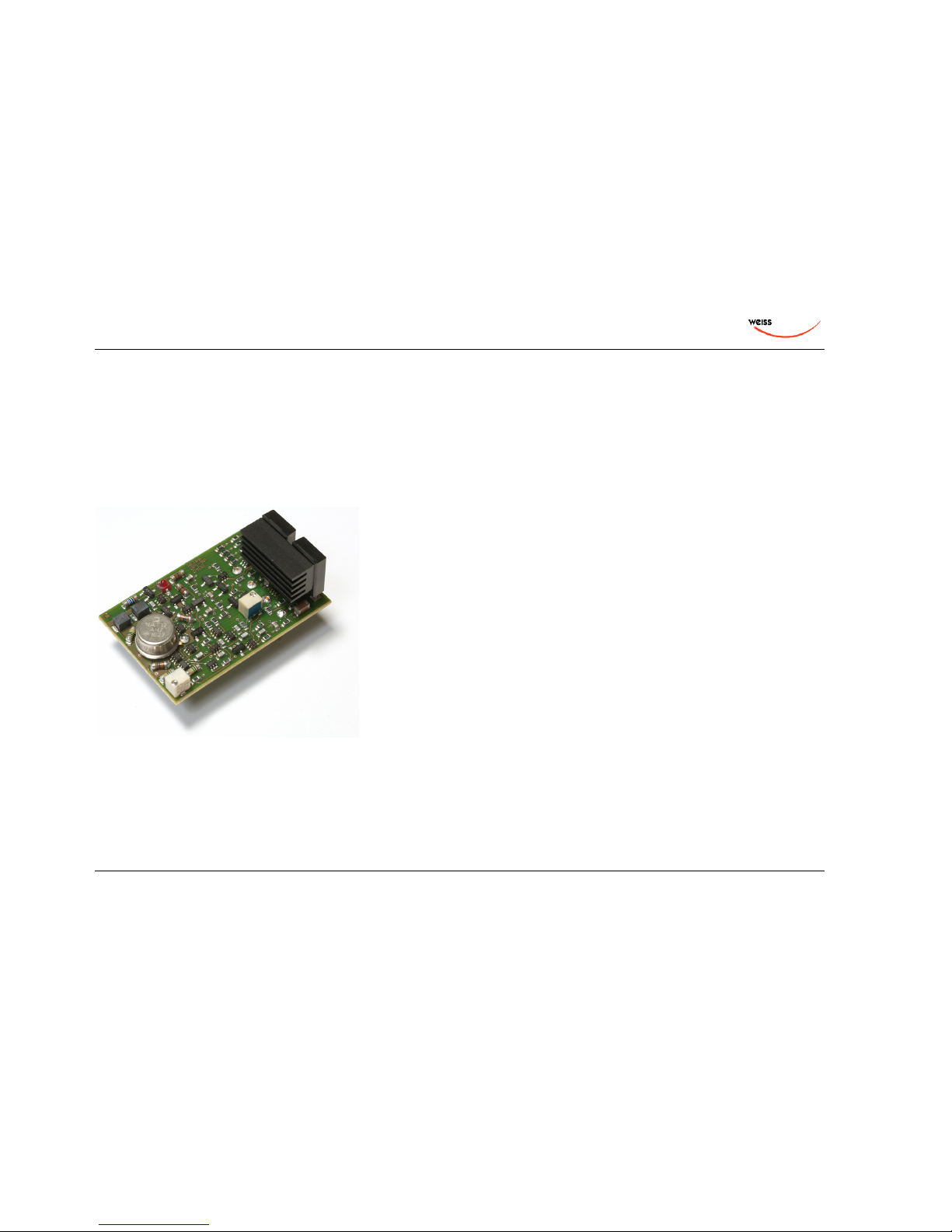
in exceptional performance specifications. The I/V conversion after the DAC chip uses two of our own discrete OP-AMPs (the
OP1-BP) per channel.
Page 16
OWNERS MANUAL FOR WEISS MEDEA+ D/A CONVERTER
Page: 16 Date: 02/11 /dw
Outputs:
Our discrete OP-AMPs are also used in the output stage, two per audio channel for a differential output. Output levels can be
set between –4.0dBu and +27.0dBu (6dB less on asymmetrical outputs). The level setting is done in 1dB steps via a rotary
switch at the back of the unit. Both outputs are set to the same level at any time. The outputs are symmetrical on XLR
connectors and asymmetrical on RCA connectors. No sound degrading servo mechanisms are used.
The Weiss OP1-BP discrete OP-AMP
Power Supply:
A powerful non-switching power supply is used. All sensitive voltages have their own regulators which are separated between
left and right channels. The result is an analog output free of "digital noise" and channel crosstalk. The power switch activates
a semiconductor relais which only switches on or off at zero crossings of the mains voltage. This assures a glitch free power
switching.
Page 17
OWNERS MANUAL FOR WEISS MEDEA+ D/A CONVERTER
Page: 17 Date: 02/11 /dw
Mechanical Design:
The MEDEA+ employs a twin metal frame. The inner chassis is made of steel and acts as a very effective shield against
electrostatic and electromagnetic radiation. The outer frame is made of massive anodized aluminium for additional shielding,
resulting in optimal heat convection and beautiful looks.
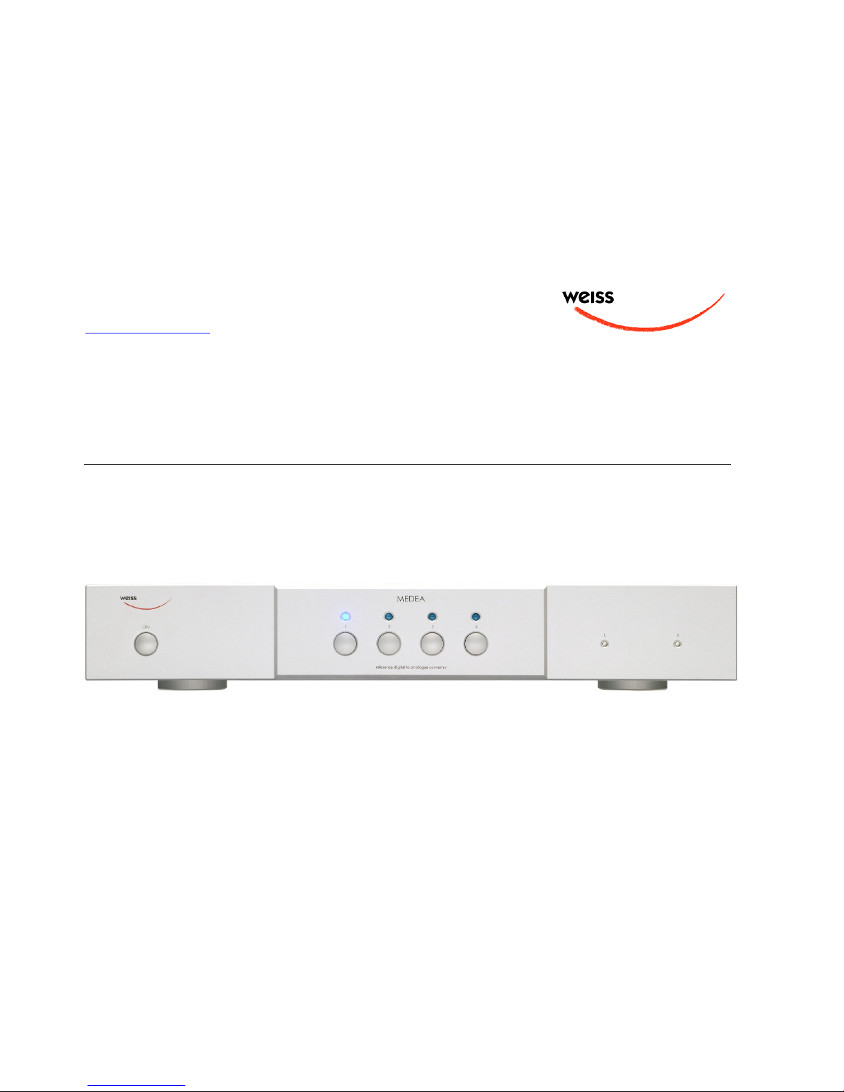
Frontpanel controls:
• Four switches with corresponding blue LEDs are used for selecting one out of four input sources.
• A power switch.
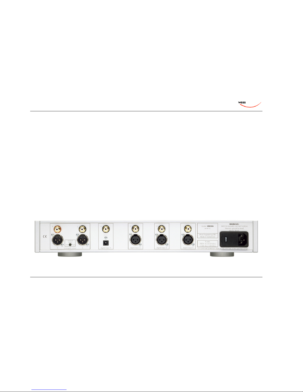
Backpanel elements from left to right:
• Analog outputs on XLR and RCA connectors with output level switch.
• Digital inputs 1 – 4 (three XLR, four RCA and one Toslink connector).
• Mains connector with fuses and voltage selector.
Page 18

OWNERS MANUAL FOR WEISS MEDEA+ D/A CONVERTER
Page: 18 Date: 02/11 /dw
Operation
Unpacking and Setup of the MEDEA+
Carfully unpack the MEDEA+. The following items should be enclosed:
• The MEDEA+ D/A Converter unit
• This Owners Manual
• A Certificate of Guarantee
The MEDEA+ should be placed horizontally on a plane surface. Avoid putting any other equipment
or any other material on top of the MEDEA+ as not to compromise the MEDEA+’s heat convection
system.
Mains Connection
Before connecting the mains cable make sure the voltage selector switch on the back of the unit
(integrated into the mains connector) is set to the appropriate voltage. If this is not the case then
open the mains selector lid with a strong screwdriver. The mains plug must not be plugged into the
connector for that purpose. Now you see a black selector drum with appropriate voltages written in
white letters. Remove this drum, turn it to the appropriate voltage and reinsert it. Now firmly close
the lid again. Connect the MEDEA+ to the wall outlet with the mains cable.
Page 19

OWNERS MANUAL FOR WEISS MEDEA+ D/A CONVERTER
Page: 19 Date: 02/11 /dw
Input Source Connection, Selection and Synchronization
Connect sources with sampling frequencies of 44.1, 48, 88.2, 96, 176.4 or 192kHz to the input
connectors at the back of the unit. Note that there are a total of four inputs. The following
connectors are available:
Input # 1: one XLR and one RCA connector (use either XLR or RCA at a time, i.e. you may connect
two sources simultaneously, but only one source unit must be switched on at a time).
Input # 2: The same as Input # 1 applies here.
Input # 3: The same as Input # 1 applies here.
Input # 4: one TOSLINK (optical) and one RCA connector (use either TOSLINK or RCA at a time,
i.e. you may connect two sources simultaneously, but only one source unit must be switched on at
a time).
The input source pushbuttons correspond to the four inputs as described above.
Input # 1 (left) and Input #2 (right) can act as an input for sources supporting the two wire
scheme, i.e. one cable per channel. The MEDEA+ automatically detects whenever such a source is
connected to inputs #1 and #2 and switches to the appropriate conversion mode. In that mode
both LEDs of input #1 and #2 are lit. The two wire scheme is used in some sources with sampling
rates of 88.2kHz or higher.
If a valid AES/EBU or S/PDIF formatted signal is present at the selected input, the blue LED stays
lit. If the format and/or the sampling frequency is not valid, the blue LED is flashing. In that case
the analog outputs are muted.
The MEDEA+ automatically synchronizes to the incoming signal. If the sampling rate of the signal
is not within a range of +- 80ppm of one of the nominal sampling rates (44.1, 48, 88.2, 96, 172.4,
192kHz) then the blue LED of the active input is flashing. The analog outputs are muted in that
case.
The states of all buttons are stored in non-volatile memory, i.e. the actual input selection is
retained when powering the unit off.
Page 20

OWNERS MANUAL FOR WEISS MEDEA+ D/A CONVERTER
Page: 20 Date: 02/11 /dw
Output Level and Output Connection
Connect your preamplifier or power amplifier to the output connectors of the MEDEA+. Use either
the symmetrical (balanced) lines (XLR) or the asymmetrical (unbalanced) lines (RCA). Or both, if
you need to feed two amplifiers. Symmetrical is preferred, provided your preamplifier supports
symmetrical connection.
The output level is set via the rotary switch on the backpanel. The position of that switch does not
indicate the output level. The switch merely acts as a rotary encoder, i.e. rotating clockwise
increases the level and vice versa. Adjust that switch to the proper output level which matches
your amplifier. If your amplifier has a volume control, adjust the MEDEA+ output such that you get
a normal listening level with the amplifier’s volume control set to about midway between minimum
and maximum volume.
Note, it is normal when after setting the rotary volume switch the MEDEA+ output mutes again for
a short time.
Page 21

OWNERS MANUAL FOR WEISS MEDEA+ D/A CONVERTER
Page: 21 Date: 02/11 /dw
Technical Data
Digital Inputs:
(3) XLR connectors, (1) Toslink connector (optical)
(4) RCA connectors
All inputs accept professional or consumer standard , i.e. accept AES/EBU or S/PDIF signals
Sampling Frequencies: single wire scheme: 44.1, 48.0, 88.2, 96.0, 176.4 or 192kHz on any of the four inputs
Sampling Frequencies: dual wire scheme: 88.2, 96.0, 176.4 or 192kHz on inputs 1 and 2
Sampling frequency tolerance: +-80ppm
Maximum input wordlength: 24 Bits
Analog Outputs:
(2) XLR Connectors
(2) RCA Connectors
Servoless, DC coupled, short circuit proof output circuitry
Output impedance: < 100 Ohm
Output level: variable from -4.0dBu to +27.0dBu balanced on XLR connectors
(-10.0dBu to +21.0dBu unbalanced on RCA connectors) with 0dBFS input, in 1dB steps
(-4dBu is 0.49V, +27dBu is 17.35V, -10dBu is 0.245V, +21dBu is 8.67V)
Output stage: Discrete Class A
Page 22

OWNERS MANUAL FOR WEISS MEDEA+ D/A CONVERTER
Page: 22 Date: 02/11 /dw
D/A
Converter chip:
Oversampling sigmal-delta converter
Four converters per channel
Synchronization:
Synchronized via input signal
Extremely efficient Jitter attenuation down to subsonic frequencies
Sampling Frequencies: 44.1 kHz, 48.0 kHz, 88.2kHz, 96.0kHz, 176.4khz, 192kHz
DSP algorithms:
Upsampling, jitter reduction, de-emphasis
Power:
Mains Voltage: 100...120 / 200...240 Volt
Fuse rating: 500 mA slow blow
Power consumption: 80VA max.
Power consumption in standby: 2VA max.
Page 23

OWNERS MANUAL FOR WEISS MEDEA+ D/A CONVERTER
Page: 23 Date: 02/11 /dw
Measurements:
The measurements below have been taken at the following conditions (unless noted otherwise):
+24.0dBu output level (-3dBFS input level), 192.0kHz sampling frequency (fs).
Frequency Response:
@ fs = 44.1kHz: 0Hz ... > 20kHz: within +- 0.25dB
@ fs = 48.0kHz: 0Hz ... > 20kHz: within +- 0.25dB
@ fs = 88.2kHz: 0Hz ... > 30kHz: within +- 0.75dB
@ fs = 96.0kHz: 0Hz ... > 30kHz: within +- 0.75dB
@ fs = 176.4kHz: 0Hz ... > 40kHz: within +- 0.75dB
@ fs = 192.0kHz: 0Hz ... > 40kHz: within +- 0.75dB
Total Harmonic Distortion plus Noise (THD+N) ratio
@ 1kHz:
< -112 dB @ -3 dBFS input (0dBFS = +27.0dBu)
< -115 dB @ 0 dBFS input (0dBFS = +27.0dBu)
Signal To Noise Ratio (SNR) @ -40dBFS input:
> 129dB unweighted (relative to full scale output)
> 132dB A–weighted (relative to full scale output)
Linearity:
at 0 to -100dBFs input level:
< +-0.05dB deviation from ideal
at -100 to -120dBFs input level:
< +-0.2dB deviation from ideal
Crosstalk:
< -110dB, 0..20kHz
Page 24

OWNERS MANUAL FOR WEISS MEDEA+ D/A CONVERTER
Page: 24 Date: 02/11 /dw
CONTACT
For any questions, suggestions etc. feel free to contact us at:
Weiss Engineering Ltd.
Florastrasse 42
8610 Uster
Switzerland
Phone: +41 44 940 20 06
Fax: +41 44 940 22 14
Email: [email protected]
Web: http://www.weiss-highend.com
http://www.weiss.ch
http://www.asiaweiss.com
Page 25

OWNERS MANUAL FOR WEISS MEDEA+ D/A CONVERTER
Page: 25 Date: 02/11 /dw
ADDENDUM FOR THE FIREWIRE INPUT FEATURE
The Firewire version of the MEDEA+ adds a Firewire input for direct audio file playback from a
computer at sampling rates of up to 192kHz. Additional features of the Firewire version are:
- Firewire socket in place of one of the XLR sockets
- IR remote sensor socket in place of a RCA socket
- IR remote for volume and polarity (active for Firewire input only)
- Bit transparency check
There are two versions of the Firewire option depending on the hardware version of the MEDEA+.
The “single wire” version uses input # 3 as the firewire input, the “dual wire” version uses inputs #
1 and # 2 for a dual wire input. Where there are differences in the operation the two versions are
mentioned separately. The versions can be distinguished by the looks of the backpanel, i.e. the
firewire socket is either at the input # 3 position or at the input # 1 position.
Synchronization:
When the firewire input is selected, the synchronization master always is the MEDEA+ unit, i.e.
the computer is slaved to the MEDEA+. The sampling rate is set via the Weiss Firewire IO
window. On a Mac system the sampling rate set in AudioMidi sets the one in the Weiss Firewire
IO window and vice versa. With the proper (advanced) player software the sampling rate of the
MEDEA+ is switched automatically depending on the track played. For more information on this
topic see the paragraph on bit transparency checking. The MEDEA+’s firewire interface intrinsic
jitter is very low.
Page 26

OWNERS MANUAL FOR WEISS MEDEA+ D/A CONVERTER
Page: 26 Date: 02/11 /dw
Software features:
The software in the MEDEA+ firewire interface allows for level control and for signal polarity
reversal. These features are only accessible via the IR remote control unit.
The level control is properly dithered, i.e. there are no artefacts due to the level control. A paper
on the topic of digital level control (including sound examples) can be found here:
http://www.weiss-highend.ch/computerplayback/Digital_Level_Control.pdf
In addition the software allows for the testing of the bit transparency of the music player program
running on the computer. This is useful to find out the proper settings / configuration of the player
program to achive bit transparency. Bit transparency means that the bits fed from the harddisk to
the INT202 are not changed in any manner.
Firewire Connection
First install the software on your computer as described in a separate paragraph below.
Then connect the computer to the MEDEA+ via an appropriate Firewire cable. There are three
types of cables applicable:
- 4 pin Firewire 400 (computer side) to 6 pin Firewire 400 (MEDEA+ side)
- 6 pin Firewire 400 (computer side) to 6 pin Firewire 400 (MEDEA+ side)
- 9 pin Firewire 800 (computer side) to 6 pin Firewire 400 (MEDEA+ side)
Chose the proper cable as required by your computer.
Make sure to plug in the Firewire cable in the proper orientation! If the connector is plugged in
reversed the MEDEA+ firewire interface can be distroyed because of the bus power on the
Firewire bus.
Page 27

OWNERS MANUAL FOR WEISS MEDEA+ D/A CONVERTER
Page: 27 Date: 02/11 /dw
The MEDEA+ should now be recognized by the computer, i.e. if you start the Weiss Firewire I/O
application the MEDEA+ shows up as a ”INT202” device. INT202 because the hardware used for
the MEDEA+ Firewire interface is a INT202 board.
You now should be able to play music from the computer through the MEDEA+.
For the single wire version select input # 3 to play the firewire input. For the dual wire version
you need to switch between input # 1 and input # 2 depending on the sampling rates:
For sampling rates of 176.4 kHz or 192 kHz select input # 1, the MEDEA+ should then go into
dual wire mode, i.e. both LEDs of input # 1 and # 2 are lit.
For all other sampling rates (44.1, 48, 88.2, 96) select input # 2.
Bit Transparency Check
In order to test the bit transparency of the player software on the computer the enclosed WAV
files (see driver CD) have to be ripped to the computer and played from the player program. The
MEDEA+ then looks for specific bit patterns coming from the firewire source. To check for bit
transparency proceed as follows:
Play the appropriate test file, there are a total of 12 files supplied. One set for 16 bit and one set
for 24 bit transparency checking. One set includes all supported sampling rates, namely 44.1,
48.0, 88.2, 96.0, 176.4, 192.0 kHz. This allows to make sure the player is bit transparent for all
sampling rates. We suggest to check first with the 24 bit files. If those yield a bit transparent
result then it is not necessary to check with the 16 bit files.
- For the single wire version: press and hold the input # 3 selection button. If the LED starts to
flash, the player software is indeed bit transparent. If the LED stays lit, the player is not bit
transparent.
- For the dual wire version: select input # 1 (independent of the sampling rate you are testing
at) and wait until the MEDEA+ locks. Then press and hold the input # 1 selection button. If
the LEDs start to flash, the player software is indeed bit transparent. If the LEDs stay lit, the
player is not bit transparent.
Page 28

OWNERS MANUAL FOR WEISS MEDEA+ D/A CONVERTER
Page: 28 Date: 02/11 /dw
During the test the output of the MEDEA+ is muted.
If the player does not seem to be bit transparent then this can have several causes, like:
- a volume control not at 0dB gain
- a equalizer
- a sampling rate conversion
- a “sound enhancer” feature and more
Make sure all those processing elements are bypassed. Particularly the sampling rate conversion
can creep in “unnoticed”. I.e. the sampling rate in the Weiss Firewire IO window has to match the
sampling rate of the file played, else a conversion is going on in the operating system. For iTunes
there is another thing to know: Whenever the sampling rate is changed in the AudioMidi setup or
the Weiss Firewire IO window, the iTunes program has to be restarted to achieve bit transparency
again. For iTunes running on a Mac computer a program like Sonic Studio’s “Amarra” is highly
recommended. With Amarra it is possible to switch the sampling rate in AudioMidi (i.e. in the
MEDEA+) automatically depending on the sampling rate of the file played. Amarra works in
conjunction with iTunes.
On a Windows based system the use of ASIO or WASAPI is highly recommended. These systems
make it simple to achieve bit transparent playback. In addition the sampling rate of the MEDEA+
is switched automatically depending on the sampling rate of the file played.
Remote Control
To use the remote control feature, the enclosed IR receiver with cable has to be plugged into the
special socket above the Firewire connector at the back of the MEDEA+. The IR receiver end then
has to be placed such that the IR control works flawlessly.
The Remote Control allows to control the volume and the phase of the digital signal transferred
by the firwire interface in the MEDEA+. The volume up / down switches control the volume
accordingly. The maximum gain is 0 dB (a gain factor of 1.0), i.e. the MEDEA+ can not amplify
the signal and thus makes sure that there are no “overs” occuring within the MEDEA+. The
“mute” switch allows to toggle between fully off (muted) and the volume set with the volume
control.
Page 29

OWNERS MANUAL FOR WEISS MEDEA+ D/A CONVERTER
Page: 29 Date: 02/11 /dw
Absolute Phase control:
Pressing the mute switch for a few seconds toggles the operation mode to phase control. In that
mode the ^ key switches the phase to 0° and the v key switches to 180° (i.e. inverted phase).
Press the mute key for a few seconds again to get back to the volume control mode. The phase
set before is retained when switching back to volume control mode. When changing the phase
with the ^ and v keys you notice a short muting of the audio. This prevents from any clicks
caused by the phase switching and also is an indication that the switching has actually taken
place.
The volume setting is retained when switching the MEDEA+ off / on, while the phase is reset to
“not inverted” after a power cycle.
With the Remote Control unit the gain can be controlled between 0dB and –60dB:
From 0dB to –20dB in 0.5dB steps and from –20dB to –60dB in 1dB steps. In the 0dB gain
position the MEDEA+’s firewire interface is fully bit transparent, i.e. it does not change the data in
any way. In all other gain positions the output signal is properly dithered to a wordlength of 24
bits.
Software installation
Perform the following installation procedure before connecting the MEDEA+ to the computer. The
necessary files are supplied on the enclosed drivers CD.
Windows:
0. Do not connect the device.
1. Double click "WeissFirewireInstaller.exe"
2. Click "Next"
3. Select the directory where you'd like to install the tools. Usually you can use the default values
and click "Next"
4. Select if you'd like to create a desktop icon. "Next"
5. Click "Install"
6. You will be asked if you'd like to continue the installation because the driver/software didn't
pass the Windows-Logo-Test. Select "Continue".
7. Select "Yes, restart the computer now" and click "Finish"
Page 30

OWNERS MANUAL FOR WEISS MEDEA+ D/A CONVERTER
Page: 30 Date: 02/11 /dw
Mac:
0. Mount the WeissFirewire.dmg diskimage by double clicking it
1. From the mounted drive double click WeissFirewire-3.3.3.3586.pkg (the version numbers can
be different of course)
2. Click "Continue"
3. Select the drive (usually you leave it at the defaults)
4. Click "Continue"
5. Click "Upgrade" or "Install"
6. You'll be asked to login as administrator
7. Confirm "Continue Installation" when warned that the computer requires a reboot after install.
8. Click Restart
After installation of the software connect the MEDEA+ to the computer. Make sure to plug in the
Firewire cable in the proper orientation! If the connector is plugged in reversed the MEDEA+
firewire interface can be distroyed because of the bus power on the Firewire bus.
The MEDEA+ should now be recognized automatically. In Windows tell the installation window
that you do not want to check the Microsoft website for drivers and then let the drivers be
installed automatically. Ignore warnings concerning “Windows Logo Test” and continue the
installation until completed. You will be asked to install drivers for "Weiss Engineering Ltd. -Firewire Unit--" and "Weiss Firewire IO MIDI". There will be two passes of installation, which is
normal.
Software setup
The connected MEDEA+ device can be controlled through the “Weiss Firewire I/O” Control Panel.
Windows:
The control panel can be accessed by clicking on the “Weiss Firewire IO” icon on the desktop.
Page 31

OWNERS MANUAL FOR WEISS MEDEA+ D/A CONVERTER
Page: 31 Date: 02/11 /dw
Device Settings / General: The device settings should be pretty self explanatory.
Device Settings / Firmware Loader: Allows to upload new firmware to the MEDEA+. Not used for
normal operation.
Global Settings / Bus:
Master: Is the device which is sync master on the virtual bus in case multiple devices
(“MEDEA+s”) are connected.
Sync Source: The clock to which the MEDEA+ should sync to. Usually this is the MEDEA+’s
internal clock generator.
Sampling Rate: The sampling rate of the device when internally clocked.
Buffer Size: Larger buffer sizes increase robustness against dropouts, lower buffer sizes provide
low latency.
Operation Mode: determines the stability of the system. Try other modes if there are clicks in the
music.
Global Settings / WDM: Enables the WDM driver.
Global Settings / DPC: Determines your computers performance and recommends a operation
mode.
Global Settings / System: Some utilities to determine the chipset in your computer and to get
information on the sup-ported chipset. Required for debugging if prob-lems with the Firewire
connection are encoun-tered.
Global Settings / Info: Information about the driver version.
Mac OSX:
Configure the MEDEA+ via the “Audio MIDI Setup” (Applications > Utilities) and the “Weiss
Firewire Control Panel” (Applications).
Device Settings / General: The device settings should be pretty self explanatory.
Page 32

OWNERS MANUAL FOR WEISS MEDEA+ D/A CONVERTER
Page: 32 Date: 02/11 /dw
Device Settings / Firmware Loader: Allows to upload new firmware to the MEDEA+. Not used for
normal operation.
Global Settings / Bus:
Master: Is the device which is sync master on the virtual bus in case multiple devices
(“MEDEA+s”) are connected.
Sync Source: The clock to which the MEDEA+ should sync to. Usually this is the MEDEA+’s
internal clock generator.
Sampling Rate: The sampling rate of the device when internally clocked.
Operation Mode: determines the stability of the system. Try other modes if there are clicks in the
music.
Global Settings / Info: Information about the driver version.
Page 33

OWNERS MANUAL FOR WEISS MEDEA+ D/A CONVERTER
Page: 33 Date: 02/11 /dw
ADDENDUM FOR THE ST GLASS FIBER INPUT FEATURE
This feature replaces the RCA connector of input # 4 with a ST type connector for a glass fiber
connection. The ST input can be used with the corresponding ST output of the JASON CD Transport
or with any other source which sports a ST output.
Also possible is to use the Weiss CHIRON-glass1T module to convert an AES/EBU output to optical
and then connect that to the ST input at the MEDEA+ via a glass fiber. For more information see
this page:
http://www.weiss-highend.ch/chiron/index.html
 Loading...