

Page 1
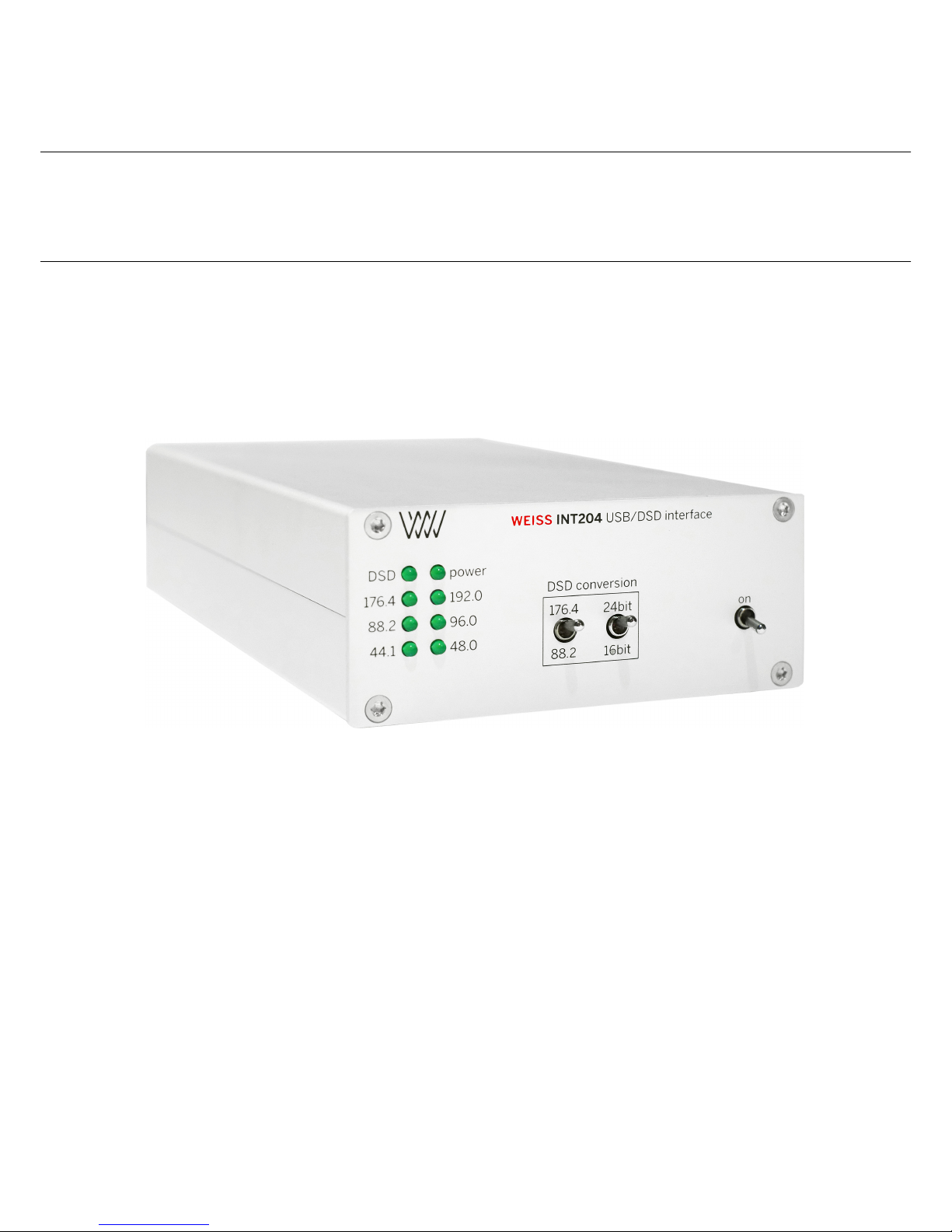
INT204
Owner’s Manual
Weiss Engineering ltd.
Florastrasse 42
8610 Uster
Switzerland
Phone: +41 44 940 20 06
Fax: +41 44 940 22 14
Email: [email protected]
Web: www.weiss.ch
www.asiaweiss.com
Page 2

ii
Page 3

iii
Introduction
Dear customer,
Congratulations on your purchase of the INT204 USB/DSD Interface and welcome
to the family of Weiss equipment owners!
On the following pages I will introduce you to our views on high quality
audio processing. These include fundamental digital and analog audio concepts
and the INT204 USB/DSD Interface.
I wish you a long-lasting relationship with your INT204.
Yours sincerely,
Daniel Weiss
President, Weiss Engineering lt d.
Page 4

iv
Copyright and Liability
Authors: Daniel Weiss, Weiss Engineering lt d.
TEXLayout: Samuel Groner & Rolf Anderegg, Weiss Engineering ltd .
Date: June 30, 2017
Weiss Engineering ltd . reserves the right to make changes to product specifica-
tion or documentation without prior notice. Updated manuals and datasheets
are available at our website for downloading. Weiss Engineering ltd . makes no
warranty, representation or guarantee regarding the suitability of its products for
any particular purpose, nor does part of this manual, and specifically disclaims
any and all liability, including without limitation consequential or incidental
damages. All rights reserved. No part of this publication may be reproduced or
transmitted in any form or by any means, electronic or mechanical including
photocopying, scanning or any information storage or retrieval system without
the express prior written consent of the publisher.
c
Copyright Weiss Engineering lt d. , 2017
Page 5

v
A Short History of Weiss
Engineering Ltd.
Having studied electrical engineering, Daniel Weiss joined the Willi Studer
(Studer-Revox) company in Switzerland. His work included the design of a
sampling frequency converter and of digital signal processing electronics for digital
audio recorders. In 1985, Mr. Weiss founded the company Weiss Engineering
ltd . From the outset the company concentrated on the design and manufacture
of digital audio equipment for mastering studios. Its first product was the
modular 102 Series system. After more than 25 years, this system is still up to
date (24 bit/96kHz).
In the early nineties the Gambit Series was launched, taking ergonomics and
sonic quality to new heights. The Gambit Series consists of stand-alone units like
equalizer, denoiser/declicker, dynamics processor, A/D converter, D/A converter,
sampling frequency converter, dithering etc. 40 bit floating point processors and
sampling rates up to 192 kHz are employed. In 2001 we have decided to enter
the High-End Hi-Fi market, which offers a comparable clientele to that of the
mastering studios. Both consist of critical and discerning listeners, who are in
constant search for the best audio reproduction equipment or the best audio
tools respectively.
Our list of clients includes big names, like SONY, BMG, EMI, Warner, Hit
Factory, Abbey Road, Teldec, Telarc, Gateway Mastering (Bob Ludwig), Bernie
Grundman Mastering, Masterdisk, Sterling Sound, Whitfield Street, Metropolis
and hundreds more. For a more comprehensive list you are invited to visit our
pro audio website at www.weiss.ch.
Today Weiss Engineering ltd . employs nine people, five of them in the
engineering department.
Our Mission and Product Philosophy
The wealth of experience we have gained in over 25 years of designing products
for top mastering engineers, we now also apply to the design of outstanding
High-End Hi-Fi products. Our mission is to create equipment which becomes
classic right from the outset — outstanding in sonics and design. These are
some of the milestones at Weiss Engineering ltd .:
Page 6

vi
1985
Introduction of the 102 Series, a 24 bit modular digital audio processor for
mastering studios
1986 Introduction of one of the first sample rate converters for digital audio
1987 Introduction of one of the first digital equalizers
1989 Introduction of one of the first digital dynamics processors
1991
Introduction of the Ibis digital mixing console, built for the mix-down of
classical music
1993
Introduction of the Gambit Series of digital audio processors, which employ
40 bit floating point processing and sport an extremely ergonomic user
interface
1995 First 96 kHz sampling rate capable products delivered
2001
Introduction of the MEDEA High-End Hi-Fi D/A Converter, the first
product in our High-End series
2004 Introduction of the JASON CD Transport
2007 Introduction of the CASTOR High-End Hi-Fi Power Amplifier
2008
Introduction of the MINERVA Firewire D/A Converter and the VESTA
Firewire-AES/EBU interface
2010
Introduction of the DAC202 Firewire D/A Converter, the INT202 Firewire
Interface and the ATT202 Passive Attenuator
2011
Introduction of the MAN301 Music Archive Network Player and the INT203
Firewire I/O Interface
2012
Introduction of the MEDEA+ D/A Converter, the MEDEA with an enhanced analog section
2013
Introduction of the INT204 USB/DSD Interface and the MEDUS State Of
The Art D/A Converter.
2017
Introduction of the DAC501/DAC502 DSP D/A Converter and Network
Renderer.
Page 7

1
Contents
Introduction iii
A Short History of Weiss Engineering Ltd. v
1 Advanced Digital & Analog Audio Concepts Explained 3
1.1 Jitter Suppression & Clocking . . . . . . . . . . . . . . . . . . . . 3
1.2 Up-/Oversampling & Sampling Rate Conversion in General . . . 4
1.3 Dithering . . . . . . . . . . . . . . . . . . . . . . . . . . . . . . . 6
1.4 Digital Level Control . . . . . . . . . . . . . . . . . . . . . . . . . 7
2 The INT204 USB/DSD Interface 11
2.1 Features . . . . . . . . . . . . . . . . . . . . . . . . . . . . . . . . 11
2.1.1 Input . . . . . . . . . . . . . . . . . . . . . . . . . . . . . 11
2.1.2 Outputs . . . . . . . . . . . . . . . . . . . . . . . . . . . . 11
2.1.3 Synchronization . . . . . . . . . . . . . . . . . . . . . . . 11
2.1.4 DSD to PCM conversion . . . . . . . . . . . . . . . . . . . 11
2.1.5 Power Supply . . . . . . . . . . . . . . . . . . . . . . . . . 12
2.1.6 Front Panel . . . . . . . . . . . . . . . . . . . . . . . . . . 12
2.1.7 Back Panel . . . . . . . . . . . . . . . . . . . . . . . . . . 12
2.2 Installation . . . . . . . . . . . . . . . . . . . . . . . . . . . . . . 12
2.2.1 Software installation . . . . . . . . . . . . . . . . . . . . . 12
2.3 Operation . . . . . . . . . . . . . . . . . . . . . . . . . . . . . . . 14
2.3.1 USB and Power Connection . . . . . . . . . . . . . . . . . 14
2.3.2 AES/EBU or S/PDIF Connection . . . . . . . . . . . . . 14
2.3.3 DSD to PCM Conversion . . . . . . . . . . . . . . . . . . 14
2.3.4 PCM to PCM Conversion . . . . . . . . . . . . . . . . . . 15
2.3.5 LED Sampling Frequency Indication . . . . . . . . . . . . 15
2.3.6 Optional IR Level Control . . . . . . . . . . . . . . . . . . 15
3 INT204 Technical Data 17
3.1 Digital Inputs . . . . . . . . . . . . . . . . . . . . . . . . . . . . . 17
3.2 Digital Outputs . . . . . . . . . . . . . . . . . . . . . . . . . . . . 17
3.3 Synchronization . . . . . . . . . . . . . . . . . . . . . . . . . . . . 17
3.4 DSD Conversion . . . . . . . . . . . . . . . . . . . . . . . . . . . 17
3.5 Power . . . . . . . . . . . . . . . . . . . . . . . . . . . . . . . . . 18
Page 8

2
A Some information on the DSD format — properties, caveats,
uses. 19
A.1 Quantizing . . . . . . . . . . . . . . . . . . . . . . . . . . . . . . 19
A.2 Filtering . . . . . . . . . . . . . . . . . . . . . . . . . . . . . . . . 19
A.3 DSD uses . . . . . . . . . . . . . . . . . . . . . . . . . . . . . . . 20
A.4 Processing . . . . . . . . . . . . . . . . . . . . . . . . . . . . . . . 20
A.5 What is better? . . . . . . . . . . . . . . . . . . . . . . . . . . . . 20
A.6 The future . . . . . . . . . . . . . . . . . . . . . . . . . . . . . . . 20
B Contact 21
Page 9

3
Chapter 1
Advanced Digital and
Analog Audio Concepts
Explained
1.1 Jitter Suppression and Clocking
What is jitter and how does it affect audio quality? In the audio field the term
jitter designates a timing uncertainty of digital clock signals. In an analog
to digital converter (A/D) the analog signal is sampled (measured) at regular
time intervals; in the case of a CD, 44 100 times a second or every 22.675737µs
(microseconds). If these time intervals are not strictly constant then one talks
of a jittery conversion clock. In practice it is of course not possible to generate
exactly the same time interval between each and every sample. After all, even
digital signals are analog in their properties and thus are influenced by noise,
crosstalk, power supply fluctuations, temperature etc.
Hence a jittery clock introduces errors to the measurements taken by the
A/D, resulting from measurements being taken at the wrong time. One can
easily observe that the level of the error introduced is higher during high audio
frequencies, because high frequency signals have a steeper signal form. A good
designer takes care that the jitter amount in his/her design is minimized as well
as possible.
What type of equipment can be compromised by jitter? There are three
types: The A/D converter as described above, then there is the D/A converter
where the same mechanism as in the A/D converter applies and the third is
the asynchronous sample rate converter (ASRC). The ASRC is not something
usually found in Hi-Fi systems. It is used by sound engineers to change the
sample rate from e.g. 96 kHz to 44.1 kHz, or e.g. for putting a 96 kHz recording
onto a 44.1 kHz CD.
You may now argue that in High-End Hi-Fi there are such things as”over-
samplers“ or”upsamplers“. Yes, those are in essence sampling rate converters,
Page 10

4
however in a well-designed system these converters employ a synchronous design,
where jitter does not play any role. Of course a conversion between 96 kHz and
44.1 kHz as in the example above can be done in a synchronous manner as well.
An ASRC in fact is only required either where one or both of the sampling
frequencies involved are changing over time (”varispeed“ mode of digital audio
recorders) or where it is unpractical to synchronize the two sampling frequencies.
So basically in Hi-Fi jitter matters where there are A/D or D/A converters
involved. CD and DVD players are by far the most numerous type of equipment
employing D/A converters. And of course stand-alone D/A converters. Jitter,
being an analog quantity, can creep in at various places. The D/A converter
built into CD or DVD players can be”infected“ by jitter through various
crosstalk mechanisms, like power supply contamination by power hungry motors
(spindle/servo), microphony of the crystal generating the sampling clock or
capacitive/inductive crosstalk between clock signals etc.
In the standalone D/A converter jitter can be introduced by inferior cables
between the source (e.g. CD transport) and the D/A converter unit or by the
same mechanisms as described above — except for the motors of course. In
the case of a stand-alone D/A converter (as the DAC202), one has to take two
different jitter contamination paths into account. One is the internal path where
internal signals can affect the jitter amount of the sampling clock generator.
Here, all the good old analog design principles have to be applied. Such as
shielding from electric or magnetic fields, good grounding, good power supply
decoupling, good signal transmission between the clock generator and the actual
D/A chip.
The other path is the external signal coming from the source to which the
sampling clock has to be locked. In other words the D/A converter has to run
synchronous to the incoming digital audio signal and thus the frequency of the
internal sampling clock generator has to be controlled so that it runs at the
same sampling speed as the source (e.g. CD transport). This controlling is done
by a phase locked loop (PLL), which is a control system with error feedback.
Of course the PLL has to be able to follow the long term fluctuations of the
source, e.g. the sampling rate of the source will alter slightly over time or over
temperature, it will not be a constant 44.1 kHz in the case of a CD. But the
PLL should not follow the short-term fluctuations (jitter). Think of the PLL as
being like a very slow-reacting flywheel.
1.2 Upsampling, Oversampling and Sampling
Rate Conversion in General
In consumer audio circles the two terms oversampling and upsampling are in
common use. Both terms essentially mean the same, a change in the sampling
frequency to higher values. Upsampling usually means the change in sampling
rate using a dedicated algorithm (e.g. implemented on a digital signal processor
chip (DSP)) ahead of the final D/A conversion (the D/A chip), while oversampling
Page 11

5
means the change in sampling rate employed in today’s modern D/A converter
chips themselves.
But let’s start at the beginning. What is the sampling frequency? For any
digital storage or transmission it is necessary to have time discrete samples of
the signal which has to be processed. I.e. the analog signal has to be sampled at
discrete time intervals and later converted to digital numbers (also see section
Jitter Suppression and Clocking, p. 3). This sampling and conversion process
happens in the so-called analog to digital converter (A/D). The inverse in the
digital to analog converter (D/A).
A physical law states that in order to represent any given analog signal in the
digital domain, one has to sample that signal with at least twice the frequency
of the highest frequency contained in the analog signal. If this law is violated so
called aliasing components are generated which are perceived as a very nasty
kind of distortion. So if one defines the audio band of interest to lie between
20 Hz and 20 kHz, then the minimum sampling frequency for such signals must
be 40 kHz.
For practical reasons explained below, the sampling frequency of 44.1 kHz
was chosen for the CD. A sampling frequency of 44.1 kHz allows to represent
signals up to 22.05 kHz. The designer of the system has to take care that
any frequencies above 22.05 kHz are sufficiently suppressed before sampling at
44.1 kHz. This suppression is done with the help of a low pass filter, which
cuts off the frequencies above 22.05 kHz. In practice such a filter has a limited
steepness, i.e. if it suppresses frequencies above 22.05 kHz it also suppresses
frequencies between 20 kHz and 22.05 kHz to some extent. So in order to have a
filter which sufficiently suppresses frequencies above 22.05 kHz, one has to allow
it to have a so-called transition band between 20 kHz and 22.05 kHz where it
gradually builds up its suppression.
Note that so far we have talked about the so-called anti-aliasing filter, which
filters the audio signal ahead of the A/D conversion process. For the D/A
conversion, which is of more interest to the High-End Hi-Fi enthusiast, essentially
the same filter is required. This is because after the D/A conversion we have a
time discrete analog signal, i.e. a signal that looks like steps, having the rate of
the sampling frequency.
Such a signal contains not only the original audio signal between 20 Hz and
20 kHz but also replicas of the same signal symmetrical around multiples of the
sampling frequency. This may sound complicated, but the essence is that there
are now signals above 22.05 kHz. These signals come from the sampling process.
There are now frequencies above 22.05 kHz which have to be suppressed, so that
they do not cause any intermodulation distortion in the amplifiers and speakers,
do not burn tweeters or do not make the dog go mad.
Again, a low pass filter, which is called a”reconstruction filter“, is here to
suppress those frequencies. The same applies to the reconstruction filter as to the
anti-aliasing filter: pass-band up to 20 kHz, transition-band between 20 kHz and
22.05 kHz, stop-band above 22.05 kHz. You may think that such a filter is rather
Page 12

6
,,steep“, e.g. frequencies up to 20 kHz go through unaffected and frequencies
above 22.05 kHz are suppressed to maybe
1
100 000
th
of their initial value. You
are right, such a filter is very steep and as such has some nasty side effects. For
instance it does strange things to the phase near the cutoff frequency (20 kHz)
or it shows ringing due to the high steepness. In the early days of digital audio
these side effects have been recognized as being one of the main culprits for
digital audio to sound bad.
So engineers looked for ways to enhance those filters. They can’t be eliminated
because we are talking laws of physics here. But what if we run the whole thing at
higher sampling rates? Like 96 kHz or so? With 96 kHz we can allow frequencies
up to 48 kHz, so the reconstruction filter can have a transition band between
20 kHz and 48 kHz, a very much relaxed frequency response indeed. So let’s run
the whole at 96 kHz or even higher! Well — the CD stays at 44.1 kHz. So in
order to have that analog lowpass filter (the reconstruction filter) to run at a
relaxed frequency response we have to change the sampling frequency before
the D/A process. Here is where the upsampler comes in. It takes the 44.1 kHz
from the CD and upsamples it to 88.2 kHz or 176.4 kHz or even higher. The
output of the upsampler is then fed to the D/A converters, which in turn feeds
the reconstruction filter. All modern audio D/A converter chips have such an
upsampler (or oversampler) already built into the chip. One particular chip,
for instance, upsamples the signal by a factor of eight, i.e. 44.1 kHz ends up at
352.8 kHz. Such a high sampling frequency relaxes the job of the reconstruction
filter very much; it can be built with a simple 3rdorder filter.
So, how come that upsamplers are such a big thing in High-End Hi-Fi circles?
The problem with the upsamplers is that they are filters again, digital ones,
but still filters. So in essence the problem of the analog reconstruction filter
has been transferred to the digital domain into the upsampler filters. The big
advantage when doing it in the digital domain is that it can be done with a
linear phase response, which means that there are no strange phase shifts near
20 kHz and the ringing can also be controlled to some extent. Digital filters in
turn have other problems and of course have quite a few degrees of freedom for
the designer to specify. This means that the quality of digital filters can vary
at least as much as the quality of analog filters can. So for a High-End Hi-Fi
designer it is a question whether the oversampling filter built into the D/A chips
lives up to his/her expectations. If not, he/she can choose to design his/her own
upsampler and bypass part of or the whole oversampler in the D/A chip. This
gives the High-End Hi-Fi designer yet another degree of freedom to optimize the
sonic quality of the product.
1.3 Dithering
You have probably not heard the term dithering in conjunction with audio.
Actually it is a term widely used in the professional audio realm but not so much
in the High-End Hi-Fi market.
Page 13

7
What is dithering? Suppose a digital recording has been made with a 24 bit
A/D converter and a 24 bit recorder. Now this recording should be transferred
to a CD, which has just 16 bits per sample, as you know. What to do with
those 8 bits, which are too many? The simplest way is to cut them off, truncate
them. This, unfortunately, generates harmonic distortions at low levels, but
which nonetheless cause the audio to sound harsh and unpleasant. The harmonic
distortion is generated because the eight bits, which are cut off from the 24 bits,
are correlated with the audio signal, hence the resulting error is also correlated
and thus there are distortions and not just noise (noise would be uncorrelated).
The dithering technique now is used to de-correlate the error from the signal.
This can be achieved by adding a very low level noise to the original 24 bit signal
before truncation. After truncation the signal does not show any distortion
components but a slightly increased noise floor. This works like magic — the
distortion is replaced by a small noise which is much more pleasant. I have given
the example of a 24 bit recording, which has to be truncated to 16 bits. Where
is the application in High-End Hi-Fi audio? More and more signal processing is
implemented in the digital domain. Think of digital equalizers, digital volume
controls, upsamplers, digital pre-amplifiers, decoders for encoded signals on DVD
etc. All those applications perform some mathematical operations on the digital
audio signal. This in turn causes the wordlength of the signal to be increased;
an input signal to an upsampler may have a wordlength of 16 bits (off a CD),
but the output signal of the upsampler may have 24 bits or even more. This
comes from the fact that the mathematical operations employed in such devices
increase the word length. A multiplication of two 2-digit numbers results in
a four-digit number. So after the upsampler the word length may be higher
than the subsequent processor may be able to accept. In this example, after
the upsampler there may be a D/A converter with a 24 bit input word length
capability. So if the upsampler generates a word length of more than 24 bits it
should be dithered to 24 bits for maximum signal fidelity.
Another application where dither is important is described in the next
paragraph.
1.4 Digital Level Control
In High-End Hi-Fi circles a level control done in the digital domain is often
viewed as being inferior to one operating in the analog domain. Let’s look on
how a digital level control works and why it can be an excellent solution if it is
properly implemented.
A level control is a multiplication of the audio signal with a constant, the
,,gain factor“. The gain factor usually is in the range of zero (signal fully off )
to one (signal untouched). A factor of 0.5 then means that the audio signal is
attenuated to half of its amplitude. What exactly happens when we multiply
two numbers? If we e.g. multiply a 2 digit and a 3 digit number, the resulting
Page 14

8
number can be up to 5 digits long (the sum 2 plus 3). As an example: 30 times
500 equals 15 000; 2 digits times 3 digits yields a 5 digit result.
In digital audio, the numbers are represented in the binary system, not the
decimal system. A decimal number consists of digits 0 through 9, a binary number
of digits 0 and 1. So a binary number may look like this: 1011 0011 0101 1101.
This is a 16 digit or 16 bit binary number, the grouping into 4 bit chunks is
for better readability. The audio samples on a CD are represented with such a
binary number system with each sample value represented with 16 bits. Now
let’s assume we have a 8 bit gain factor for a level control. If we apply that to
a signal coming off a CD we multiply a 8 bit gain factor with a 16 bit sample
value. The result is up to 24 bits long (the sum of the wordlengths of the two
factors). An example:
0100 1001 × 1001 0110 0111 1011 = 0010 1010 1110 1001 0001 0011
The question now is what do we do with the 24 bit long result? The digital to
analog converter which converts the samples after the level control may only
be capable to handle 16 bit wide samples. Thus what should we do with the
excessive 8 bits? The simplest solution is to truncate the 24 bit sample to 16 bits,
i.e. to cut off the 8 least significant bits. The truncated 24 bit result above then
would look like this: 0010 1010 1110 1001 i.e. the first 16 bits of the 24 bit result
above.
The remaining bits (0001 0011) are discarded. If these bits are discarded an
error is introduced. This error is called a quantization error, because the 24 bit
result is requantized to 16 bits. Unfortunately the quantization error is part of
the audio signal — and if we take that part away from the signal, the signal
undergoes some distortion, the so called quantization distortion. The sound
example at the link below shows how such a distortion sounds. In this music
example a 16 bit signal is truncated to 8 bits; 8 bits in order to clearly show the
effect. Notice how the noise (distortion) is modulated by the music signal.
www.weiss.ch/linked/digital-level-control/nodither.mp3
This is how a badly implemented digital level control works. . . Fortunately there
is a better way to handle the re-quantizing. One solution would be to use a D/A
converter with a higher wordlength, e.g. a 24 bit converter, to accommodate for
the 24 bit samples coming out of the level control. This of course would already
help a lot, but there is another technique: dithering.
The idea about dithering is to de-correlate the quantization error from the
audio signal. As we have seen in the example above, the quantization error
depends on the audio signal (i.e. it is correlated with the audio signal). On the
other hand, if dither noise is added to the 24 bit sample after the level control
and before the re-quantization to 16 bits, the quantization error can be fully
decorrelated from the signal. This means instead of distortion there is noise.
The music is undistorted. The audio example at the link below is again a 16 bit
signal quantized to 8 bits, but with dither noise added. A much more pleasant
Page 15

9
experience. Notice how the noise stays untouched by the music, i.e. there is no
noise modulation.
www.weiss.ch/linked/digital-level-control/flatdither.mp3
Dithering does not stop here. More elaborate dithering schemes shape the noise
such that it is mainly present at higher frequencies where the human ear is less
sensitive. This means that the audible noise is much lower. The link below is
again the 16 bit source quantized to 8 bits with noise-shaped dithering. Probably
hard to believe that this is only an 8 bit system! Note that the music is not
distorted at all, despite the 8 bit resolution. Remember, a 16 bit system has
65 536 quantization steps while a 8 bit system has only 256 quantization steps —
a huge difference. And still, the properly dithered 8 bit system sounds great.
www.weiss.ch/linked/digital-level-control/shapeddither.mp3
This is what a properly dithered level control is capable to do. You have heard
the 8 bit version, imagine that with today’s 24 bit converters — no question that
a level control with a 24 bit wordlength easily rivals the best analog level controls.
By the way, 24 bits means 16 777 216 quantization steps.
The last example below toggles the noiseshaping dither on and off to give a
good contrast between dither/no dither versions.
www.weiss.ch/linked/digital-level-control/togglingdither.mp3
Dithering is used in many disciplines. Also see
en.wikipedia.org/wiki/Dithering
A paper on this topic (including image examples) can be found here:
www.weiss.ch/assets/content/41/white-paper-on-digital-level-control.pdf
I hope these excursions into the theory and practice of audio engineering has been
useful for you. If you would like to dive further into those issues I recommend
visiting the website of Mr. Bob Katz, a renowned mastering engineer and a Weiss
Engineering ltd . customer. He publishes articles on dithering and jitter and
many other topics at
www.digido.com
Page 16

10
Page 17

11
Chapter 2
The INT204 USB/DSD
Interface
2.1 Features
2.1.1 Input
There is one USB type B socket for connecting a computer. The supported
sampling frequencies are 44.1, 48.0, 88.2, 96.0, 176.4, 192.0, 352.8, 384.0 kHz and
DSD over PCM (DoP) at 2.8224 MHz and 5.6448 MHz (DSD64, DSD128).
2.1.2 Outputs
There is one each of XLR, BNC and RCA connectors available on the back
panel. The XLR has its own driver while the RCA and BNC connectors have
one common driver. All three outputs carry the same data.
2.1.3 Synchronization
The synchronization master is always the INT204 device, i.e. the computer is
slaved to the INT204. The sampling frequency is set via the USB driver. On
a Mac system the sampling frequency is set in AudioMidi application. With
the proper (advanced) player software the sampling frequency of the INT204 is
switched automatically depending on the track played. The INT204’s intrinsic
jitter is very low.
2.1.4 DSD to PCM conversion
In case of DSD playback, the DSD signal is converted to PCM. The sampling
frequency and word length of the PCM signal can be chosen to match the
capabilities of the D/A Converter connected to the INT204.
Page 18

12
2.1.5 Power Supply
The INT204 uses two power sources. One is the bus power coming via the USB
connector. It powers the USB input section of the INT204, which is isolated from
the rest of the circuit. The rest of the circuit (output section etc.) is powered
via the external power supply which is supplied with the INT204.
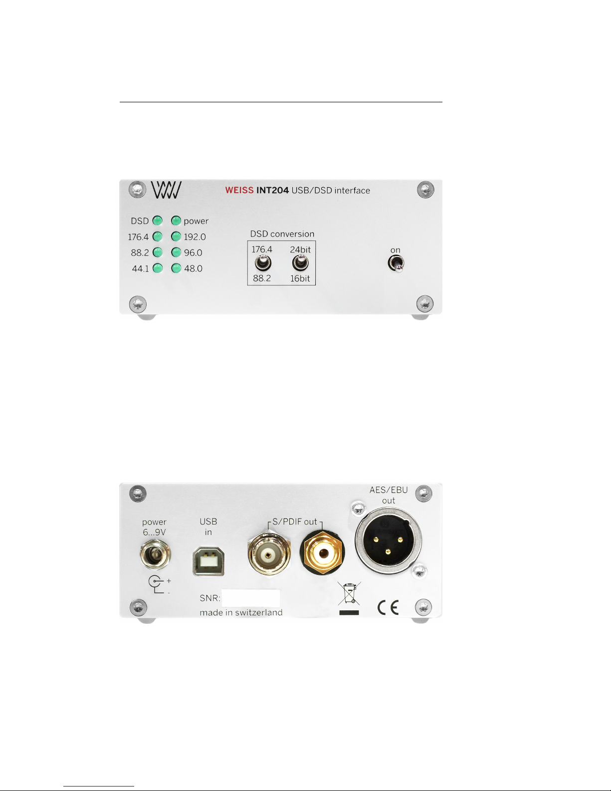
2.1.6 Front Panel
• Power switch
•
DSD conversion mode switches for word length and sampling frequency
selection
• LEDs for power indication and sampling frequency indication
• IR Receiver
2.1.7 Back Panel
• (1) XLR connector
• (1) RCA connector
• (1) BNC connector
• (1) USB type B connector
• (1) Power connector
2.2 Installation
Carefully unpack the INT204. The following items should be enclosed:
• the INT204 USB/DSD Interface unit
• a Power Supply
•
a CD with the necessary drivers for Windows. OSX does not require any
driver.
• this Owner’s Manual
• a Certificate of Guarantee
2.2.1 Software installation
Perform the following installation procedure before connecting the INT204 to
the computer. The necessary files are supplied on the enclosed driver CD.
For Windows:
• Launch SETUP.EXE found on the driver CD and follow the instructions.
Page 19
13
Figure 2.1: INT204 frontpanel
Figure 2.2: INT204 backpanel
Page 20

14
•
Click on
Accept
when MS Windows warns you about unverified driver
installation.
• Plug the USB cable according the installation wizard messages.
• Use MS Windows control panel to set up the audio interface correctly.
• Configure your media player to use the USB Audio ASIO driver.
For OSX:
• No driver to be installed.
2.3 Operation
2.3.1 USB and Power Connection
First install the software on your computer as described in section 2.2.1 (not
necessary for OSX). Connect the computer to the INT204 via an appropriate
USB cable. Use an USB cable as short as practicable. Connect the enclosed
power supply to the power inlet at the INT204. Switch on the computer and
the INT204. The INT204 should now be recognized by the computer and should
appear in the audio devices settings. Select the INT204 as the playback device.
2.3.2 AES/EBU or S/PDIF Connection
Connect the output of the INT204 to your D/A Converter or any other digital
audio device. Use either the XLR or RCA or BNC connectors as applicable.
You may connect more than one D/A Converter simultaneously. When using
the BNC and RCA outputs simultaneously it may fail to work though, as the
BNC and RCA connectors are driven by a single driver. But do not hesitate to
try. Make sure to use an appropriate cable to connect the D/A Converter to
the INT204. E.g. the XLR cable must be one suited for AES/EBU signals. An
”
analog“ type AES/EBU cable must not be used.
2.3.3 DSD to PCM Conversion
In case of DSD playback, the DSD signal is converted to PCM. The sampling
frequency and word length of the PCM signal can be chosen to match the
capabilities of the D/A Converter connected to the INT204. The options are:
•
Sampling frequency: 176.4 or 88.2 kHz. Use the 88.2 kHz setting if your
D/A Converter cannot handle the 176.4 kHz sampling frequency.
•
Word length: 24 or 16 bit. Use the 16 bit setting if your D/A Converter
cannot handle a word length of 24 bit.
The conversion of the DSD signal to PCM before the D/A conversion has some
advantages compared to a native DSD D/A conversion. The white paper in the
appendix A gives details about that topic.
Page 21

15
2.3.4 PCM to PCM Conversion
In case of 352.8 kHz playback, the sampling frequency will be converted to 176.4
kHz. In case of 384.0 kHz playback, the sampling frequency will be converted to
192.0 kHz.
2.3.5 LED Sampling Frequency Indication
The 8 LEDs indicate the power status as well as the input sampling frequency
and format. In case of 352.8 kHz or 384.0 kHz input sampling frequencies only
the power LED is lit.
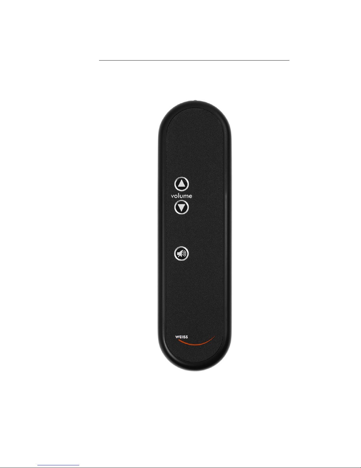
2.3.6 Optional IR Level Control
There is an optional IR Remote Control unit available for the INT204. This
allows to control the volume in the digital domain. If the IR Remote Control is
not included with the INT204, the volume control is factory set to 0 dB gain,
i.e. there isn’t any influence on the audio signal.
Page 22
16
Figure 2.3: INT204 remote control
Page 23

17
Chapter 3
INT204 Technical Data
3.1 Digital Inputs
• (1) USB type B connector
•
Sampling Frequencies: 44.1, 48.0, 88.2, 96.0, 176.4, 192.0, 352.8, 384.0 kHz
or DSD over PCM (DoP) at 2.8224 or 5.6448 MHz.
• Maximum input wordlength: 24 bits
3.2 Digital Outputs
• (1) XLR connector
• (1) RCA connector
• (1) BNC connector
• Channel Status Data bits are set to all 0 on all three outputs
3.3 Synchronization
•
Synchronized via the clock internal to the INT204, i.e. the computer is
slaved to the INT204
•
Sampling Frequencies: 44.1, 48.0, 88.2, 96.0, 176.4, 192.0, 352.8 or 384.0kHz
3.4 DSD Conversion
The DSD to PCM conversion can be configured to match the capabilities of the
D/A Converter connected to the INT204. The sampling frequency can be chosen
between 176.4 and 88.2 kHz while the output word length can be chosen between
24 and 16 bit.
Page 24

18
3.5 Power
Bus power via the USB input for the USB input section. External power supply
for the output section. External power supply voltage: 6–9 V DC at 0.15 A.
The USB input is isolated from the digital audio outputs and from the external
power supply.
Page 25

19
Appendix A
Some information on the
DSD format — properties,
caveats, uses.
The DSD (Direct Stream Digital) Audio format is used with the well-known
SACD disc. The SACD has some form of copy protection implemented, thus an
SACD is not easily rip-able into a computer file.
A.1 Quantizing
DSD is a digital signal which uses a 1 bit quantization of the audio signal at a
sampling rate of 64 times the sampling rate of a CD (64×44100Hz= 2.8224 MHz).
The CD format uses a 16 bit quantization at a 44.1 kHz sampling rate, thus the
data rate of a DSD signal is four times the data rate of a CD, which gives the
SACD the potential to represent the audio signal more precisely. The noise floor
of a signal at 44.1 kHz/16 bit is about 16×6dB= 96 dB below full scale. With
the DSD signal the noise floor is 1×6 dB below full scale, so obviously there have
to be taken some measures to get down the noise floor, else a DSD recording
would be very noisy. Here the high sampling rate of DSD comes in handy. I.e.
with special filtering techniques (noise-shaping) it is possible to move the noise
in the audio band (0–20 kHz) out to higher frequencies above 20 kHz. Thus the
noise floor in the audio band can be brought down to very low levels (well below
the 16 bit noise floor of a CD) at the cost that the noise is at a fairly high level
at frequencies above 20 kHz.
A.2 Filtering
This high level/high frequency noise has to be suppressed before the signal
hits the amplifier and speakers, in order to avoid amplifier misbehaving and/or
speaker blow-up. A low pass filter is used to suppress the noise. In a native
Page 26

20
DSD D/A Converter this low pass filter has to be implemented in the analog
domain which can be problematic because the non-linear phase characteristics of
such a filter. Alternatively this filter can be implemented in the digital domain
where the DSD signal is converted to PCM (at e.g. 176.4 kHz/24 bit) and at the
same time gets properly low pass filtered, e.g. with a linear phase filter which is
easily achievable in the digital domain.
A.3 DSD uses
The DSD format initially was conceived for distribution and archiving. Later on
it became more and more popular in music recording with its own set of problems
as described below. DSD shows the state of the art of the 90ies. The 1 bit
sigma-delta A/D and D/A converters were very popular at that time. Converter
techniques have progressed though. Today the modern sigma-delta converters
are multi-bit designs with e.g. 6 bits instead of 1 bit. This for good reasons of
course, the 1 bit technique has some inherent problems with dithering and idle
tones. If the SACD was conceived today, it would use a 6 bit format.
A.4 Processing
If a recording made in DSD has to be processed, e.g. the loudness has to be
adjusted or some equalizing is required, then the DSD signal has to be converted
to PCM in order to be able to do the processing. In the PCM format the signal
can be processed, i.e.”produced“ as required in order to get a final version. In
such a case it does not make sense to do a recording in DSD to start with. A
PCM recording at e.g. 88.2 kHz/24bit would make much more sense. After the
production process the file can always be converted to DSD if required.
A.5 What is better?
The discussion whether DSD is better than PCM is moot. DSD is another
variant to store music, like PCM, MP3, magnetic tape, vinyl etc. All formats
are fine as long as there are people preferring one over the other for whatever
reasons. A matter of taste or practical reasons as with MP3 for instance.
A.6 The future
Technically speaking, PCM from like 88.2 kHz/24 bit up, is definitively better
than DSD. There are attempts to enhance DSD by rising the sampling rate from
2.8824 MHz to 5.6448 MHz or even 11.2896 MHz. Some problems of DSD may
be reduced with such measures, but the 1 bit quantization problem cannot be
eliminated. With the DSD downloads becoming more and more popular the
DSD format is going to stay with us. A niche, but a growing one.
Page 27

21
Appendix B
Contact
For any questions, suggestions etc. feel free to contact us at:
Weiss Engineering ltd .
Florastrasse 42
8610 Uster
Switzerland
www.asiaweiss.com
Page 28

22
 Loading...