

Page 1
digital audio
weiss engineering ltd.
Florastrasse 42, 8610 Uster, Switzerland
) +41 1 940 20 06 2 +41 1 940 22 14
8 http://www.weiss.ch / http://www.weiss-highend.com
GAMBIT
DAC1-MK2
OPERATING MANUAL
Software Version: OS: 3.1
DSP: 2.1
Page 2

OPERATING INSTRUCTIONS FOR GAMBIT DAC1-MK2 24Bit / 192kHz D/A CONVERTER INTRODUCTION
INTRODUCTION
Congratulations on purchasing the Weiss Gambit Series DAC1-MK2 D/A Converter !
The DAC1-MK2 is a stereo 24 bit / 192khz D/A
converter designed with the aim of keeping an
absolutely uncompromised audio signal path.
Much detail and thought was spent on the digital
input as well as the analogue output stage. Both
have in common the purest possible approach in
audio design, aspiring for nothing less than excellence. This is coupled with an ergonomic design
that gives the user immediate access to all necessary functions, while keeping an uncluttered and
thus easy-to-use front panel. This combination
makes a truly professional D/A converter catering
for the highest expectations.
Features
* Inputs:
There are three digital inputs on XLR con-
nectors, and one on Toslink (optical). The accepted sampling frequencies are 44.1, 48,
88.2, 96, 176.4 and 192kHz. For 44.1kHz
through 96kHz sampling frequencies, signals
on a single connector are used. For 176.4 or
196kHz signals on two connectors (dual wire
scheme) are used. Each XLR input is actively
routed to a corresponding XLR digital output,
allowing monitoring at multiple stages in a
digital studio setup.
* Synchronization:
Several signal reclocking schemes are com-
bined for extremely high jitter attenuation,
making the DAC1-MK2 virtually immune to
jitter frequencies in the range from fractions
of a Hertz up to tens of kHz.
The correlation technique (using two converters per channel) which was already successfully employed in the ADC1 A/D Converter gives the DAC1-MK2 an edge over
other D/A converters with equal wordlength
and sampling rate specifications, resulting in
improved SNR and THD.
* Outputs:
The discrete Class A outputs have a virtually
zero Ohm output impedance, but can still
drive complex loads without stability problems. Output levels can be set between infinity and +27dBu. The outputs are symmetrical, but do not have any sound degrading servo mechanisms built in. For asymmetrical operation only pin 2 of the XLR connector plus ground on pin 1 are used, pin 3
must be left open.
* Remote Control:
By hooking up an analog potentiometer or
fader to the remote connector, the output
level can be remote controlled. A stereo potentiometer or fader allows to control the
two channels independently. This level control happens in the digital domain and is dithered in order to avoid any sound degrading
quantization effects. The input source selection can also be remote controlled. Four input selection pushbuttons and associated
status LEDs are brought to the remote connector.
* Converters:
Daniel Weiss Engineering Ltd., Florastr. 42, CH-8610 Uster Page 2 of 8
) +41 1 940 20 06 2 +41 1 940 22 14 8 http://www.weiss.ch / http://www.weiss-highend.com
Page 3

OPERATING INSTRUCTIONS FOR GAMBIT DAC1-MK2 24Bit / 192kHz D/A CONVERTER INTRODUCTION
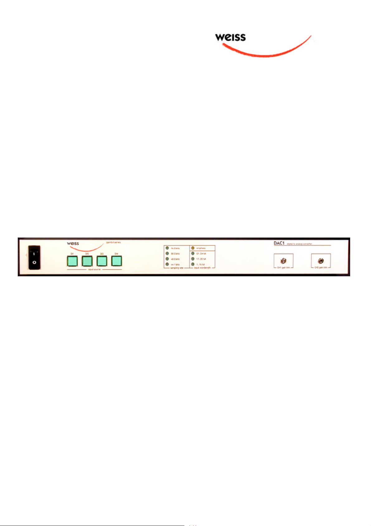
Frontpanel Elements
* Four switches for input selection
* Four LEDs for sampling frequency dis-
play (44.1 / 48 / 88.2 / 96)
* Three LEDs for input wordlength dis-
play (1..16, 17..20, 21..24 bits)
* One Emphasis LED
* Two 18 turn trim potentiometers for
fine trimming the output level
Backpanel Elements
* Three digital inputs on XLR
* One digital input on Toslink
* Three digital outputs on XLR, buffered
from XLR inputs
* One switch for monitor source selec-
tion on DO3
* Two analog outputs on XLR
* Output level range switch (high / low)
* Remote connector with the following
signals:
- Power supply to external faders
- Tapers from two external faders
- Four input selection switches
- Four LEDs for input selection
switches
Daniel Weiss Engineering Ltd., Florastr. 42, CH-8610 Uster Page 3 of 8
) +41 1 940 20 06 2 +41 1 940 22 14 8 http://www.weiss.ch / http://www.weiss-highend.com
Page 4

OPERATING INSTRUCTIONS FOR GAMBIT DAC1-MK2 24Bit / 192kHz D/A CONVERTER OPERATION
OPERATION
Input Source Selection
Synchronization
The input source pushbuttons correspond to the
three XLR and the single Toslink input connectors.
If a valid AES/EBU or S/PDIF formatted signal is
present at the selected input, its sampling rate,
wordlength and emphasis status are indicated via
the status LEDs.
The wordlength LEDs are blank if the input signal
is muted.
If the sampling rate is valid, the analog outputs
are activated. Blank sampling rate LEDs indicate
that the format or sampling rate at the input are
not valid. In that case the analog outputs are
muted.
The DAC1 is always slaved to the selected input.
Because the jitter reduction circuitry in the DAC1
is of the highest possible quality, sepaarate external or internal synchronization is not necessary.
For applications in surround setups with more
than one DAC1 unit operating in parallel, we will
offer a software version which assures a determined, constant delay from input to output. In
the current software version this is not the case,
i.e. the delay from input to output can vary.
The states of all buttons are stored in non-volatile
memory, i.e. the setup is retained when powering
the unit off.
For 176.4 or 192kHz signals the two channels are
connected as follows: Left channel to input 1,
Right channel to input 2. To activate, press the
input 1 key. If such a signal is present at the input
of the DAC1-MK2, the software automatically
detects that and switches the D/A accordingly.
Also both input 1 and input 2 keys are lit. If you
press the input 2 key with such a two wire signal
present at inputs 1 and 2, the DAC1-MK2 interprets the signal at input 2 as a normal two channel AES/EBU signal. I.e. do not select input 2
when feeding a two wire signal.
For the three XLR inputs a corresponding XLR
output is available. These outputs are buffered
clones of the input signals. The purpose is to loop
in the DAC1 at various points in the signal chain
for monitoring.
For the third output (DO3) the source can be
selected to be either Input 3 (DI3) or the currently selected input. This allows to use the
DAC1 as a monitor switch.
Output Level and Output Connection
The output level is set via the "high / low" switch
on the backpanel and via the trim potentiometers
on the frontpanel. For output levels between
+15dBu and +27 dBu balanced (or +9dBu and
+21dBu unbalanced) set the switch to "high". For
all other levels set it to "low". These output level
figures are reached for 0dBFS at the input of the
DAC1.
After that, adjust the trim potentiometers to
match the output level required.
Note that the output amplifiers of the DAC1 are
powerful class A type discrete circuits. This
means that the power dissipation is quite high, so
it is absolutely normal for the DAC1 unit to heat
up.
Important: For unbalanced operation of the
DAC1 connect pin 1 (ground) and pin 2
(hot) of the output connectors to your amplifier. Pin 3 must be left open!
Daniel Weiss Engineering Ltd., Florastr. 42, CH-8610 Uster Page 4 of 8
) +41 1 940 20 06 2 +41 1 940 22 14 8 http://www.weiss.ch / http://www.weiss-highend.com
Page 5

OPERATING INSTRUCTIONS FOR GAMBIT DAC1-MK2 24Bit / 192kHz D/A CONVERTER OPERATION
Remote Control Connector
A self-made remote control can be hooked up to
the remote control connector. Following is the
description of how such a circuitry should look
like. The pin numbers refer to the 15 pin remote
connector pin numbers.
The remote level control changes the level in the
digital domain, i.e. it is independent of the other
level control facilities of the DAC1. Because of
the 24 bit digital resolution of the DAC1, controlling the level in the digital domain is not critical
for the sonic quality or the signal to noise ratio.
This level remote can be used as a monitor room
level control.
The input source switches and lamps work in
parallel to the frontpanel controls of the DAC1.
Level control:
Connect one or two faders or potentiometers
with a linear characteristic and an impedance
between 1kOhm and 10kOhm as follows:
The maximum voltage across the switch is 5V,
the maximum current is 5mA.
Input source indication lamps:
Connect either an ordinary light bulb or an LED.
Depending on the required voltage a series resistor might be necessary. The DAC1 internal
circuit consists of a switching transistor which
connects the lamp output to +5V via a 10 Ohm
resistor. The other side of the lamp goes to
ground.
E.g. you might use a 6V lamp rated at 100mA
without any additional resistor. If in doubt then
just try, you can't break anything.
For LEDs an additional 100 Ohm series resistor is
recommended.
Connect as follows:
Anode Input 1 to pin 5
Anode Input 2 to pin 12
Anode Input 3 to pin 6
Anode Input 4 to pin 13
ground to pin 7
taper CH1 to pin 14
taper CH2 to pin 15
hot end to pin 8
If a single fader or potentiometer is used then
connect its taper to both pin 14 and 15.
Input source selection:
Connect four momentary switches as follows:
one side of all switches to pins 1,2 (ground) the
other sides for:
Input 1 to pin 10
Input 2 to pin 3
Input 3 to pin 11
Input 4 to pin 4
All cathodes to pins 1,2 (ground)
Daniel Weiss Engineering Ltd., Florastr. 42, CH-8610 Uster Page 5 of 8
) +41 1 940 20 06 2 +41 1 940 22 14 8 http://www.weiss.ch / http://www.weiss-highend.com
Page 6

OPERATING INSTRUCTIONS FOR GAMBIT DAC1-MK2 24Bit / 192kHz D/A CONVERTER TECHNICAL DATA
TECHNICAL DATA
Three AES/EBU Inputs
Input fs range: 44.1kHz +- 80ppm
48.0kHz +- 80ppm
88.2kHz +- 80ppm
96.0kHz +- 80ppm
176.4kHz +- 80ppm
192.0kHz +- 80ppm
Maximum Input Wordlength: 24 Bits
Channel Status Data: Input accepts professional or consumer format.
Connector: XLR female
Impedance: 110 Ohm
Three AES/EBU Outputs
Clones of the corresponding input, actively buffered. DO3 can be switched between DI3 and selected input.
Connector: XLR male
One Toslink Optical Input
Connector: Standard plastic fiber Toslink type
Two Analog Outputs
Symmetrical, not earth free, no servo circuit.
Connector: XLR male, pin1 ground, pin 2 hot, pin 3 return
For asymmetrical use connect pin 1 to ground, use pin 2 as hot and leave pin 3 unconnected! Do
not connect pin 2 or pin 3 to ground!
Daniel Weiss Engineering Ltd., Florastr. 42, CH-8610 Uster Page 6 of 8
) +41 1 940 20 06 2 +41 1 940 22 14 8 http://www.weiss.ch / http://www.weiss-highend.com
Page 7

OPERATING INSTRUCTIONS FOR GAMBIT DAC1-MK2 24Bit / 192kHz D/A CONVERTER TECHNICAL DATA
Remote Connector
15 pin DSUB connector pinout:
1 ground
2 ground
3 key # 2 (switch to ground, selects input # 2)
4 key # 4 (switch to ground, selects input # 4)
5 LED # 1 (anode of LED for key # 1, cathode at ground)
6 LED # 3 (anode of LED for key # 3, cathode at ground)
7 ground
8 +5V supply for external fader (connect fader between +5V and ground)
9 n.c.
10 key # 1 (switch to ground, selects input # 1)
11 key # 3 (switch to ground, selects input # 3)
12 LED # 2 (anode of LED for key # 2, cathode at ground)
13 LED # 4 (anode of LED for key # 4, cathode at ground)
14 fader channel 1 taper
15 fader channel 2 taper
Power
Mains Voltage: 110 / 220 Volts with voltage selector
Fuse rating: 500 mA slow blow
Power Consumption: 80VA max.
Daniel Weiss Engineering Ltd., Florastr. 42, CH-8610 Uster Page 7 of 8
) +41 1 940 20 06 2 +41 1 940 22 14 8 http://www.weiss.ch / http://www.weiss-highend.com
Page 8

OPERATING INSTRUCTIONS FOR GAMBIT DAC1-MK2 24Bit / 192kHz D/A CONVERTER TECHNICAL DATA
Measurements
Measurements taken at the following conditions (unless otherwise noticed):
+27dBu output level, 44.1kHz sampling frequency (fs), 22kHz measurement bandwidth
Frequency Response: @ fs = 44.1kHz: DC ... > 20kHz +- 0.05dB
@ fs = 48.0kHz: DC ... > 20kHz +- 0.05dB
@ fs = 88.2kHz: DC ... > 40kHz +- 0.5dB
@ fs = 96.0kHz: DC ... > 40kHz +- 0.5dB
Dynamic Range: 115dB unweighted, 118dB A-weighted
THD+N @ 1kHz: -107 dBr @ -3 dBFs input (0dBr = +27dBu)
-105 dBr @ 0 dBFs input (0dBr = +27dBu)
SNR @ -40dBFS input: 114dBr unweighted (0dBr = +27dBu)
117dBr A - weighted (0dBr = +27dBu)
Linearity: from 0 to -100dBFs input level: < +-1dB deviation from ideal
from -100 to -130dBFs input level: < +-1.5dB deviation from ideal
Crosstalk: < -130dB, 0..20kHz
Output Level Range: range switch "high", balanced: +27dBu ... - dBu
range switch "low", balanced: +15dBu ... - dBu
range switch "high", unbalanced: +21dBu ... - dBu
range switch "low", unbalanced: +9dBu ... - dBu
Output impedance: 0.2 Ohm, outputs are short circuit proof
Daniel Weiss Engineering Ltd., Florastr. 42, CH-8610 Uster Page 8 of 8
) +41 1 940 20 06 2 +41 1 940 22 14 8 http://www.weiss.ch / http://www.weiss-highend.com
 Loading...