

Page 1

Installation and operating instruction
Replacing combustion manager W-FM 20 … 24 with W-FM 25
83294002 • 2/2014-11
Page 2

60040000
Conformity certification
Manufacturer:
Address:
Product: Combustion Manager
The product described above conforms with
the regulations of directives:
This product is labelled as follows:
Schwendi, 02.09.2014
ppa. ppa.
Dr. Schloen Denkinger
Manager Research Manager Production and
and Development Quality Management
Max Weishaupt GmbH
Max-Weishaupt-Straße
D-88475 Schwendi
W-FM 25
GAD 2009 / 142 / EC
PED
97 / 23 / EC
LVD 2006 / 95 / EC
EMC 2004 / 108 / EC
Sprachschlüssel
02
CE-0085
Page 3

Installation and operating instruction
Replacing combustion manager W-FM 20 … 24 with W-FM 25
1 User instructions ..................................................................................................................... 5
1.1 User guide ............................................................................................................. 5
1.1.1 Symbols ................................................................................................................. 5
1.1.2 Target group ......................................................................................................... 5
1.2 Guarantee and Liability ....................................................................................... 6
2 Safety ............................................................................................................................................ 7
2.1 Designated application ....................................................................................... 7
2.2 When gas can be smelled ................................................................................. 7
2.3 Safety measures .................................................................................................. 7
2.3.1 Normal operation ................................................................................................. 7
2.3.2 Electrical connection ........................................................................................... 7
2.3.3 Gas supply ............................................................................................................ 8
2.4 Alterations to the construction of the equipment ......................................... 8
2.5 Noise emission ..................................................................................................... 8
2.6 Disposal ................................................................................................................. 8
3 Product description ............................................................................................................... 9
3.1 Inputs and outputs ............................................................................................... 9
3.1.1 Gas burner ............................................................................................................ 9
3.1.2 Gas burner with speed control ...................................................................... 10
3.1.3 Oil burner ............................................................................................................ 11
3.1.4 Dual fuel burner ................................................................................................. 12
3.2 Technical data ................................................................................................... 13
3.2.1 Electrical data ................................................................................................... 13
3.2.2 Ambient conditions ........................................................................................... 13
3.2.3 Dimensions ......................................................................................................... 13
4 Operation .................................................................................................................................. 14
4.1 Operating panel ................................................................................................ 14
4.2 Display ................................................................................................................. 16
4.2.1 Info level .............................................................................................................. 17
4.2.2 Service level ....................................................................................................... 20
4.2.3 Parameter level .................................................................................................. 23
4.2.4 Access level ....................................................................................................... 28
4.3 Linearisation ....................................................................................................... 29
5 Installation ................................................................................................................................ 30
5.1 Replacing the combustion manager ............................................................. 30
83294002 • 2/2014-11 • La
6 Commissioning ...................................................................................................................... 32
6.1 Gas burner ......................................................................................................... 32
6.2 Gas burner with speed control ...................................................................... 37
6.3 Oil burner ............................................................................................................ 42
6.4 Dual fuel burner ................................................................................................. 47
6.4.1 Adjusting gas side ............................................................................................ 47
6.4.2 Adjusting oil side ............................................................................................... 52
3-70
Page 4

Installation and operating instruction
Replacing combustion manager W-FM 20 … 24 with W-FM 25
7 Troubleshooting .................................................................................................................... 57
7.1 Procedures for fault conditions ..................................................................... 57
7.1.1 Display off ........................................................................................................... 57
7.1.2 Display flashes ................................................................................................... 57
7.1.3 Detailed fault code ........................................................................................... 58
7.2 Rectifying faults ................................................................................................. 59
8 Spares ......................................................................................................................................... 64
9 Technical documentation ................................................................................................. 66
9.1 Program sequence ........................................................................................... 66
10 Notes ........................................................................................................................................... 68
11 Key word index ...................................................................................................................... 70
83294002 • 2/2014-11 • La
4-70
Page 5

Installation and operating instruction
Replacing combustion manager W-FM 20 … 24 with W-FM 25
1 User instructions
1 User instructions
This installation and operating manual forms part of the appliance and must be kept
on site.
Observe installation and operating manual of the burner.
This installation and operating manual supplements the following chapters in the in-
stallation and operating manual of the burner:
Technical description and/or Product description
▪
Commissioning and operation and/or Commissioning
▪
Cause and rectification of faults and/or Troubleshooting
▪
Technical data.
▪
The chapter Display and operating modes and operation is replaced completely.
1.1 User guide
1.1.1 Symbols
DANGER
WARNING
CAUTION
Immediate danger with high risk.
Non observance can lead to serious injury or death.
Danger with medium risk.
Non observance can lead to environmental damage,
serious injury or death.
Danger with low risk.
Non observance can cause damage to the equipment
and injury to personnel.
Important information
Requires direct action
Result after an action
Itemisation
83294002 • 2/2014-11 • La
Range of values
1.1.2 Target group
These installation and operating instructions are intended for the operator and qualified personnel. They should be observed by all personnel working on the unit.
Work on the unit must only be carried out by personnel who have the relevant training
and instruction.
Persons with limited physical, sensory or mental capabilities may only work on the unit
if they are supervised or have been trained by an authorised person.
Children must not play near or on the unit.
5-70
Page 6

Installation and operating instruction
Replacing combustion manager W-FM 20 … 24 with W-FM 25
1 User instructions
1.2 Guarantee and Liability
Guarantee and liability claims for personal and equipment damage are excluded, if
they can be attributed to one or more of the following causes:
Non approved application,
▪
non-observance of the installation and operating instruction,
▪
operation with faulty safety equipment,
▪
continual operation despite a fault,
▪
improper installation, commissioning, operation and service,
▪
unauthorised modifications made to the unit,
▪
the installation of additional components, which have not been tested with the unit,
▪
the installation of combustion chamber inserts, which impede full flame formation,
▪
repairs, which have been carried out incorrectly,
▪
the use of non original Weishaupt parts,
▪
unsuitable fuels,
▪
defects in the inlet lines,
▪
acts of God.
▪
83294002 • 2/2014-11 • La
6-70
Page 7

Installation and operating instruction
Replacing combustion manager W-FM 20 … 24 with W-FM 25
2 Safety
2 Safety
2.1 Designated application
The combustion manager W-FM 25 is suitable for use with:
oil burners
▪
gas burners
▪
dual fuel burners.
▪
Improper use could:
endanger the health and safety of the user or third parties,
▪
cause damage to the appliance or other material assets.
▪
2.2 When gas can be smelled
Avoid open flames and spark generation, for example:
do not operate light switches,
▪
do not operate electronic equipment,
▪
do not use mobile telephones.
▪
Open doors and windows.
▶
Close gas isolating valve.
▶
Warn the inhabitants (do not ring door bells).
▶
Leave the building.
▶
Inform the heating company or gas supplier from outside of the building.
▶
2.3 Safety measures
Safety relevant fault conditions must be eliminated immediately.
2.3.1 Normal operation
All labels on the unit must be kept in a legible condition,
▪
the unit should only be operated with its cover in the closed position,
▪
do not touch moving parts during operation,
▪
stipulated settings, service and inspection work should be carried out at regular
▪
intervals.
2.3.2 Electrical connection
For work carried out on live parts:
Observe the accident prevention instructions BGV A3 and adhere to local direc-
▪
tives,
tools in accordance with EN 60900 should be used.
▪
83294002 • 2/2014-11 • La
7-70
Page 8

Installation and operating instruction
Replacing combustion manager W-FM 20 … 24 with W-FM 25
2 Safety
2.3.3 Gas supply
Only the gas supplier or an approved agent may carry out installation, alteration
▪
and maintenance work on gas appliances in buildings and properties.
Pipe work must be subject to a combined load and valve proving test and usability
▪
testing relative to the pressure range intended (e.g.
DVGW-TRGI, work sheet G 600).
Inform the gas supplier about the type and size of plant prior to installation.
▪
Local regulations and guidelines must be observed during installation (e. g.
▪
DVGW-TRGI, work sheet G 600; TRF Band 1 and Band 2).
The gas supply pipe work should be suitable for the type and quality of gas and
▪
should be designed in such a way that it is not possible for liquids to form (e. g. condensate). Observe vaporisation pressure and vaporisation temperature of liquid
petroleum gas.
Use only tested and approved sealing materials, whilst observing all process in-
▪
formation.
Re-commission the appliance when changing to a different type of gas.
▪
Carry out soundness test after each service and fault rectification.
▪
2.4 Alterations to the construction of the equipment
All conversions require written approval from Max Weishaupt GmbH.
No additional components may be fitted, which have not been tested for use with
▪
the equipment,
use only original Weishaupt replacement parts.
▪
2.5 Noise emission
The noise emissions are determined by the acoustic behaviour of all components fitted
to the combustion system.
Prolonged exposure to high noise levels can lead to loss of hearing. Provide operating
personnel with protective equipment.
Noise emissions can further be reduced with a sound attenuator.
2.6 Disposal
Dispose of all materials used in a safe and environmentally friendly way. Observe local
regulations.
83294002 • 2/2014-11 • La
8-70
Page 9

Installation and operating instruction
Replacing combustion manager W-FM 20 … 24 with W-FM 25
3 Product description
3 Product description
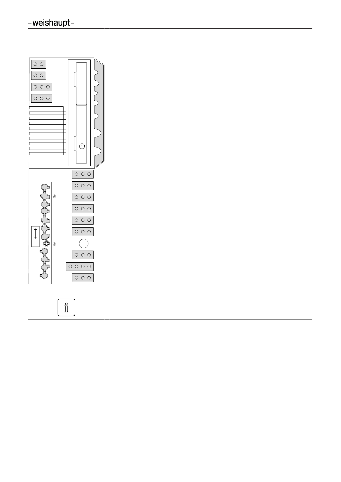
3.1 Inputs and outputs
3.1.1 Gas burner
8
11
-weishaupt-
L
N
X6
F7
X7
T1
T2
S3
B4
B5
T6
T7
T8
15
12
TWI TWI interface (Vision Box)
P free
TWI
NA free
FC free
AM Operating panel of remote reset
L/A Air damper actuator
G Gas butterfly valve actuator
1
Slot analogue module EM3/3 or Fieldbus module EM3/2
1 External liquid petroleum gas valve
G L/A AM FU NA P
3C Burner motor for continuous running fan
3N Burner motor or valve continuous running fan
4 Ignition unit
13
3
N
7
3
C
4
1
5 Multifunction assembly or double gas valve
6 free
7 Bridging plug No. 7
8 Gas meter (impulse generator)
11 Air pressure switch
12 Low / valve proving gas pressure switch
13 Ionisation
14 Remote reset (plug cable No. 14 required)
15 Bridging plug No. 15 or high gas pressure switch
6
5
X6 7 pole connection plug
X7 4 pole connection plug
F7 Internal unit fuse (6.3 AT)
14
83294002 • 2/2014-11 • La
If a digital load converter (DLU) is used, this has to be replaced with the
analogue module EM3/3.
9-70
Page 10
8
11
-weishaupt-
L
N
X6
F7
X7
T1
T2
S3
B4
B5
T6
T7
T8
15
12
Installation and operating instruction
Replacing combustion manager W-FM 20 … 24 with W-FM 25
3 Product description
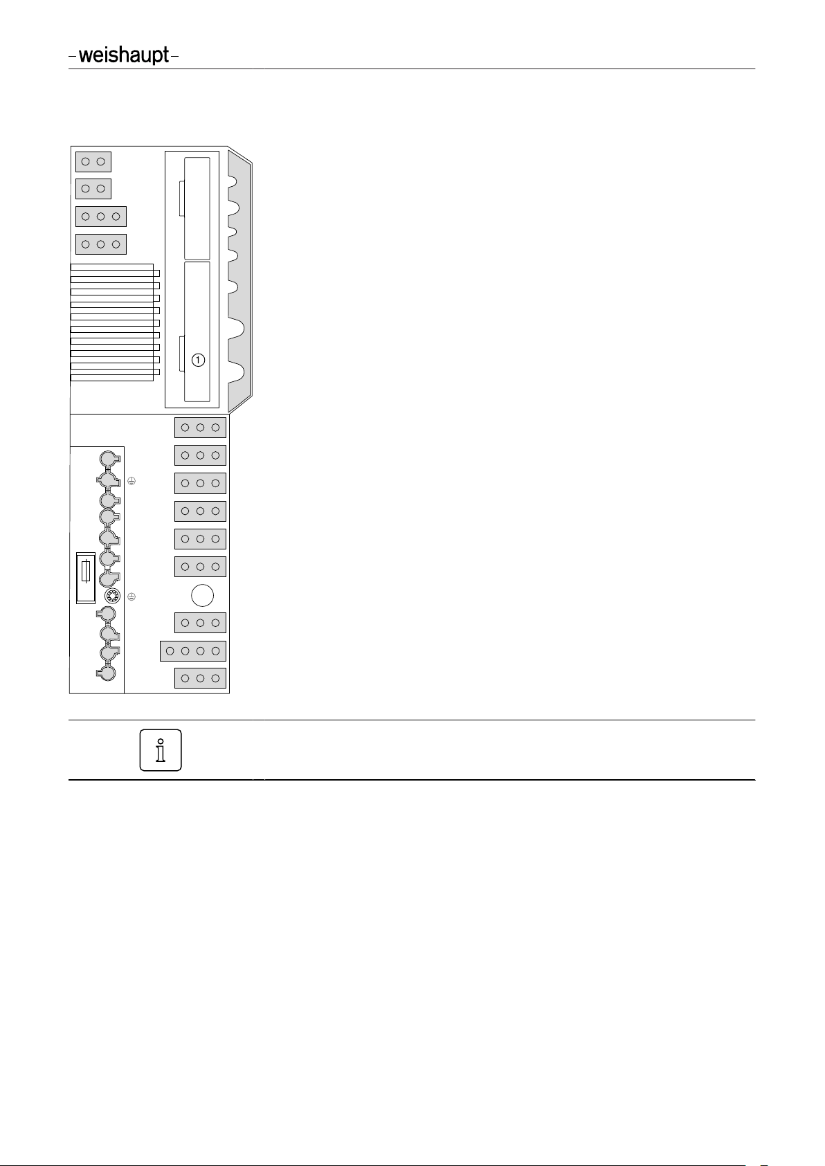
3.1.2 Gas burner with speed control
TWI TWI interface (Vision Box)
P free
TWI
G L/A AM FU NA P
13
3
N
7
3
C
4
1
6
5
14
NA free
FC free
AM Digital/analogue converter (DAU01)
L/A Air damper actuator
G Coded plug (yellow)
1
Slot analogue module EM3/3 or Fieldbus module EM3/2
1 External liquid petroleum gas valve
3C Digital/analogue converter (DAU01)
3N Frequency converter
4 Ignition unit
5 Double gas valve and air pressure switch burner operation
6 free
7 Low gas pressure switch
8 Gas meter (impulse generator)
11 Air pressure switch pre-purge
12 Valve proving gas pressure switch
13 Ionisation
14 Remote reset (plug cable No. 14 required)
15 Bridging plug No. 15 or high gas pressure switch
X6 7 pole connection plug
X7 4 pole connection plug
F7 Internal unit fuse (6.3 AT)
If a digital load converter (DLU) is used, this has to be replaced with the
analogue module EM3/3.
83294002 • 2/2014-11 • La
10-70
Page 11

Installation and operating instruction
Replacing combustion manager W-FM 20 … 24 with W-FM 25
3 Product description
3.1.3 Oil burner
8
11
-weishaupt-
L
N
X6
F7
X7
T1
T2
S3
B4
B5
T6
T7
T8
15
12
TWI TWI interface (Vision Box)
P free
TWI
NA free
FC free
AM Operating panel of remote reset
L/A Air damper actuator
G Coded plug (black)
1
Slot analogue module EM3/3 or Fieldbus module EM3/2
1 Safety solenoid valve (Y14)(1 or stage 1 solenoid valve (Y11)
G L/A AM FU NA P
3C Burner motor for continuous running fan
(2
3N Burner motor
4 Ignition unit
13
5 Stage 1 solenoid valve (Y11)
3
N
7
3
C
4
1
6 Stage 2 solenoid valve (Y12)
7 Bridging plug No. 7
8 Oil meter (impulse generator)
11 free
12 Bridging plug No. 12 or oil pressure switch
13 Flame sensor
14 Remote reset (plug cable No. 14 required)
(1
15 free
6
5
X6 7 pole connection plug
X7 4 pole connection plug
F7 Internal unit fuse (6.3 AT)
14
(1
Burner with safety solenoid valve
(2
Burner without safety solenoid valve
83294002 • 2/2014-11 • La
If a digital load converter (DLU) is used, this has to be replaced with the
analogue module EM3/3.
11-70
Page 12
Installation and operating instruction
Replacing combustion manager W-FM 20 … 24 with W-FM 25
3 Product description
3.1.4 Dual fuel burner
8
11
-weishaupt-
L
N
X6
F7
X7
T1
T2
S3
B4
B5
T6
T7
T8
15
12
TWI TWI interface (Vision Box)
P free
TWI
NA free
FC free
AM Operating panel of remote reset
L/A Air damper actuator
G Gas butterfly valve actuator
1
Slot analogue module EM3/3 or Fieldbus module EM3/2
1 Stage 1 solenoid valve (Y11)
G L/A AM FU NA P
3C Pump motor and safety solenoid valve Oil (Y14)
3N Burner motor and external LPG valve
4 Ignition unit
13
3
N
7
3
C
4
1
5 Multifunction assembly or double gas valve
6 Stage 2 solenoid valve (Y12)
7 Bridging plug No. 7
8 Fuel change-over
11 Air pressure switch
12 Low / valve proving gas pressure switch and oil pressure switch
13 Flame sensor
14 Remote reset (plug cable No. 14 required)
15 Bridging plug No. 15 or high gas pressure switch
6
5
X6 7 pole connection plug
X7 4 pole connection plug
F7 Internal unit fuse (6.3 AT)
14
If a digital load converter (DLU) is used, this has to be replaced with the
analogue module EM3/3.
83294002 • 2/2014-11 • La
12-70
Page 13
Installation and operating instruction
Replacing combustion manager W-FM 20 … 24 with W-FM 25
3 Product description
3.2 Technical data
3.2.1 Electrical data
Mains voltage/frequency 230 V / 50 … 60 Hz
Consumption max 12 W
Internal unit fuse 6.3 A slow
Type of protection IP 40
3.2.2 Ambient conditions
Temperature in operation -20 … +60 °C
Temperature during transport / storage -20 … +70 °C
Relative humidity DIN 60730-1,
no dew point
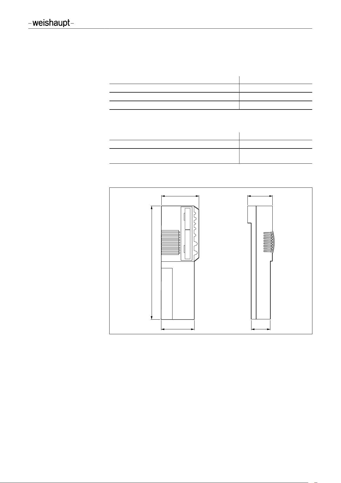
3.2.3 Dimensions
275 mm
92 mm 60 mm
-weishaupt-
80 mm 46 mm
83294002 • 2/2014-11 • La
13-70
Page 14
Installation and operating instruction
Replacing combustion manager W-FM 20 … 24 with W-FM 25
4 Operation
4 Operation
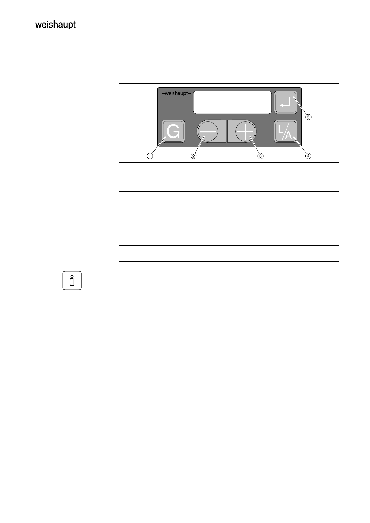
4.1 Operating panel
No. Key Function
1 [G] Gas Select gas butterfly valve actuator or speed
control
2
3
4
5
3 and 5 [+] and [ENTER] press approx. 2 seconds = Parameter level
[–]
[+]
[L/A] Air Select air damper actuator
[ENTER] Reset burner; call up information
Change values
press approx. 0.5 seconds = Info level
press approx. 2 seconds = Service level
(only possible with display
OFF
)
Various actions (e. g. changing the display, reset) are only triggered when the key is
released.
Operating level
The current actuator position or the fan speed can be displayed by pressing keys in
operating level (10).
Displaying air damper setting:
Press key [L/A].
▶
Displaying gas butterfly valve setting or fan speed:
Press key [G].
▶
Off function
Press keys [ENTER], [L/A] and [G] simultaneously.
▶
Immediate lockout with error
✓
18h
.
83294002 • 2/2014-11 • La
14-70
Page 15

Installation and operating instruction
Replacing combustion manager W-FM 20 … 24 with W-FM 25
4 Operation
Operating phase
The exact operating phase of the combustion manager can also be displayed. This
simplifies determining the cause of the fault during troubleshooting (see Ch. 9.1).
The display can be called up in Standby (
Press and hold keys [+] and [–] simultaneously for approx. 3 seconds.
▶
The combustion manager changes to operating display. In the display, the current
✓
operating phase is shown with a number.
Switching back to standard display:
Press and hold keys [+] and [–] simultaneously for approx. 3 seconds.
▶
OFF
).
83294002 • 2/2014-11 • La
15-70
Page 16

Installation and operating instruction
Replacing combustion manager W-FM 20 … 24 with W-FM 25
4 Operation
4.2 Display
Operating panel
The display shows the current operating status and operating data.
1
Setting level activated
2
Start phase activated
3
Info level activated
4
Actuator runs CLOSED
5
Actuator runs OPEN
6
Burner in operation
7
Lockout
8
Service level activated
No heat demand
No heat demand
(fuel selected: Gas)
No heat demand
(fuel selected: Oil)
Shutdown via contact X3:7 (plug No. 7)
Programming not completed
Programming of gas part not completed
83294002 • 2/2014-11 • La
Programming of oil part not completed
Switch off via Fieldbus
Insufficient gas low gas pressure switch
Low voltage (display flashes)
Connection to Fieldbus faulty (display flashes)
16-70
Page 17

Installation and operating instruction
Replacing combustion manager W-FM 20 … 24 with W-FM 25
4 Operation
4.2.1 Info level
Gas burner / gas burner with speed control
Burner data can be interrogated in the Info level.
Press [Enter] key approx. 0.5 seconds.
▶
The Info level is activated.
✓
Press [Enter] to reach the next information.
▶
l,m³
No. Information
0
1
2
3
4
5
6
7
8
9
11
12
13
Total gas consumption in m³ (via X3:8)
Reset value:
Press [L/A] and [+] keys simultaneously for ca. 2 secs.
▶
Operating hours
- no function Burner starts
Device item number
Index of device item number
Unit number
Production date (DDMMYY)
Fieldbus address
Valve proving behaviour
- no function Current gas consumption (0.1 m³/h)
Analogue module EM3/3 or Fieldbus module EM3/2 available
0
= No
1
= Yes
After information 13 or a waiting time of approx. 20 seconds the combustion manager
changes over to the operating level.
83294002 • 2/2014-11 • La
17-70
Page 18

Installation and operating instruction
Replacing combustion manager W-FM 20 … 24 with W-FM 25
4 Operation
Oil burner
Burner data can be interrogated in the Info level.
Press [Enter] key approx. 0.5 seconds.
▶
The Info level is activated.
✓
Press [Enter] to reach the next information.
▶
l,m³
No. Information
0
1
2
3
4
5
6
7
8
10
11
12
13
Total oil consumption in litres (via X3:8)
Reset value:
Press [L/A] and [+] keys simultaneously for ca. 2 secs.
▶
Operating hours stage 1
Operating hours stage 2
Burner starts
Device item number
Index of device item number
Unit number
Production date (DDMMYY)
Fieldbus address
Oil pressure switch function
- no function Current oil consumption (0.1 l/h)
Analogue module EM3/3 or Fieldbus module EM3/2 available
0
= No
1
= Yes
After information 13 or a waiting time of approx. 20 seconds the combustion manager
changes over to the operating level.
83294002 • 2/2014-11 • La
18-70
Page 19

Installation and operating instruction
Replacing combustion manager W-FM 20 … 24 with W-FM 25
4 Operation
Dual fuel burner
Burner data can be interrogated in the Info level.
Press [Enter] key approx. 0.5 seconds.
▶
The Info level is activated.
✓
Press [Enter] to reach the next information.
▶
l,m³
No. Information
0
1
2
3
4
5
6
7
8
9
10
11
12
13
- no function Operating hours in gas operation or oil operation stage 1
Operating hours in oil operation stage 2
Total burner starts
Device item number
Index of device item number
Unit number
Production date (DDMMYY)
Fieldbus address
Valve proving behaviour
Oil pressure switch function
- no function -
- no function Analogue module EM3/3 or Fieldbus module EM3/2 available
0
= No
1
= Yes
After information 13 or a waiting time of approx. 20 seconds the combustion manager
changes over to the operating level.
83294002 • 2/2014-11 • La
19-70
Page 20

Installation and operating instruction
Replacing combustion manager W-FM 20 … 24 with W-FM 25
4 Operation
4.2.2 Service level
Gas burner / dual fuel burner (Gas operation)
The service level gives information about:
Actuator position of individual operating points
▪
The most recent fault
▪
Flame signal during operation.
▪
Press [ENTER] key for approx. 2 seconds.
▶
The service level is activated.
✓
Press [Enter] to reach the next information.
▶
No. Information
0
1
2
3
4
5
6
7
8
9
10
…
Actuator position in operating point P
Actuator position in operating point P
Actuator position in operating point P
Actuator position in operating point P
Actuator position in operating point P
Actuator position in operating point P
Actuator position in operating point P
Actuator position in operating point P
Actuator position in operating point P
Actuator position in operating point P
18
most recent fault … ninth last occurred fault
Display additional information:
0
1
2
3
4
5
6
7
8
9
1. Detailed fault code / operating phase
Press [+] key.
▶
2. Detailed fault code
Press keys [+] and [-] simultaneously.
▶
3. Detailed fault code
Press key [L/A].
▶
Repetition counter
Press key [G].
▶
19
After information 19 or a waiting time of approx. 20 seconds the combustion manager
changes over to the operating level.
Flame signal:
00
= no flame ... 58 = high intensity
83294002 • 2/2014-11 • La
20-70
Page 21

Installation and operating instruction
Replacing combustion manager W-FM 20 … 24 with W-FM 25
4 Operation
Gas burner with speed control
The service level gives information about:
Actuator position of individual operating points
▪
The most recent fault
▪
Flame signal during operation.
▪
Press [ENTER] key for approx. 2 seconds.
▶
The service level is activated.
✓
Press [Enter] to reach the next information.
▶
No. Information
0
1
9
10
…
Fan speed and air damper setting in operating point P
Fan speed and air damper setting in operating point P
Fan speed and air damper setting in operating point P
18
most recent fault … ninth last occurred fault
Display additional information:
0
1
9
1. Detailed fault code / operating phase
Press [+] key.
▶
2. Detailed fault code
Press keys [+] and [-] simultaneously.
▶
3. Detailed fault code
Press key [L/A].
▶
Repetition counter
Press key [G].
▶
19
After information 19 or a waiting time of approx. 20 seconds the combustion manager
changes over to the operating level.
Flame signal:
00
= no flame ... 58 = high intensity
83294002 • 2/2014-11 • La
21-70
Page 22

Installation and operating instruction
Replacing combustion manager W-FM 20 … 24 with W-FM 25
4 Operation
Oil burner / dual fuel burner (oil operation)
The service level gives information about:
Actuator position of individual operating points
▪
The most recent fault
▪
Flame signal during operation.
▪
Press [ENTER] key for approx. 2 seconds.
▶
The service level is activated.
✓
Press [Enter] to reach the next information.
▶
No. Information
0
1
2
3
9
10
…
Actuator position in operating point P
Actuator position in operating point P
Actuator position in operating point P2 (switch off point stage 2 when
running closed)
Actuator position in operating point P3 (switch on point stage 2 when
running open)
Actuator position in operating point P
18
most recent fault … ninth last occurred fault
Display additional information:
0
1
9
1. Detailed fault code / operating phase
Press [+] key.
▶
2. Detailed fault code
Press keys [+] and [-] simultaneously.
▶
3. Detailed fault code
Press key [L/A].
▶
Repetition counter
Press key [G].
▶
19
After information 19 or a waiting time of approx. 20 seconds the combustion manager
changes over to the operating level.
Flame signal
Oil burner:
255
Dual fuel burner:
00
121
…
= no flame ... 58 = high intensity
= no flame ... 1 = high intensity
83294002 • 2/2014-11 • La
22-70
Page 23

Installation and operating instruction
Replacing combustion manager W-FM 20 … 24 with W-FM 25
4 Operation
4.2.3 Parameter level
Gas burner
The parameter level can only be called up in Standby (
Press [+] and [Enter] keys simultaneously for approx. 2 seconds.
▶
The parameter level is activated.
✓
l,m³
Press [+].
▶
Press [Enter] to reach the next information.
▶
Pno. Information Range of values Factory
1
2
Fieldbus address
Actuator position in Standby
0
254
…
Switch over to
Briefly press [+] and [-] keys simultaneously.
▶
0.0
…
OFF
/
90.0
OFF
and to address:
°
OFF
) mode.
setting
OFF
0.0
Adjust air damper setting:
Press [L/A] and [+] keys or press [-] key.
▶
Adjusting gas butterfly valve setting:
Press [G] and [+] keys or press [-] key.
▶
4
5
6
A
b
C
d
E
F
(1
Post-purge time
Fault history
Factor for gas consumption
Impulse rate of meter per m³
Low / valve proving gas pressure switch (X3:12)
Air pressure switch (X3:11)
(display only, no adjustment
possible)
Operating mode output X3:1
Flame sensor
Display mode
Restart attempts following
flame failure
Following commissioning, set parameter E to
After parameter F or a waiting time of approx. 20 seconds the combustion manager
changes over to the operating level.
0
…
0
= Fault memory is empty
1
= Fault memory contains data
Delete fault memory:
Press [L/A] and [+] keys simultaneously for ca. 2 secs.
▶
1
…
200 impulses ≙ 1 m³
Adjust factor depending on impulse rate of gas meter
▶
0
= not activated
1
= Proof-of-closure (valve 1)
2
= without low gas pressure switch
3
= with low gas pressure switch
0
= not activated
1
= activated
0
= not activated
1
= with pilot valve not interrupted
2
= with pilot valve interrupted
3
= Standard (external LPG valve)
0
= Ionisation electrode / flame sensor FLW
1
= switch input (X3:14)
2
= flame sensor QRB
On
= Parameter E0 … E4 not activated in setting mode
OFF
0
…
4095
s
65535
= Parameter E0 … E4 activated in setting mode
1 1
OFF
.
2
–
200
3
1
3
0
On
(1
83294002 • 2/2014-11 • La
23-70
Page 24

Installation and operating instruction
Replacing combustion manager W-FM 20 … 24 with W-FM 25
4 Operation
Gas burner with speed control
The parameter level can only be called up in Standby (
Press [+] and [Enter] keys simultaneously for approx. 2 seconds.
▶
The parameter level is activated.
✓
l,m³
Press [+].
▶
Press [Enter] to reach the next information.
▶
OFF
) mode.
Pno. Information Range of values Factory
setting
1
2
Fieldbus address
Actuator position in Standby
0
254
…
Switch over to
Briefly press [+] and [-] keys simultaneously.
▶
0.0
…
OFF
/
90.0
OFF
and to address:
°
OFF
0.0
Adjust air damper setting:
Press [L/A] and [+] keys or press [-] key.
▶
Changing the fan speed:
Press [G] and [+] keys or press [-] key.
▶
4
5
Post-purge time
Fault history
0
4095
…
0
= Fault memory is empty
1
= Fault memory contains data
s
Delete fault memory:
Press [L/A] and [+] keys simultaneously for ca. 2 secs.
▶
6
Factor for gas consumption
Impulse rate of meter per m³
A
Low / valve proving gas pressure switch (X3:12)
b
Air pressure switch (X3:11)
(display only, no adjustment
1
65535
…
200 impulses ≙ 1 m³
Adjust factor depending on impulse rate of gas meter
▶
0
= not activated
1
= Proof-of-closure (valve 1)
2
= without low gas pressure switch
3
= with low gas pressure switch
0
= not activated
1
= activated
possible)
C
d
E
F
Operating mode output X3:1
Flame sensor
Display mode
Restart attempts following
0
= not activated
1
= with pilot valve not interrupted
2
= with pilot valve interrupted
3
= Standard (external LPG valve)
0
= Ionisation electrode / flame sensor FLW
1
= switch input (X3:14)
2
= flame sensor QRB
On
= Parameter E0 … E4 not activated in setting mode
OFF
= Parameter E0 … E4 activated in setting mode
0
1 1
…
flame failure
(1
On gas burners with speed control, parameter A must be set to 2.
(2
Following commissioning, set parameter E to
OFF
.
After parameter F or a waiting time of approx. 20 seconds the combustion manager
changes over to the operating level.
2
–
200
(1
3
1
3
0
On
(2
83294002 • 2/2014-11 • La
24-70
Page 25

Installation and operating instruction
Replacing combustion manager W-FM 20 … 24 with W-FM 25
4 Operation
Oil burner
The parameter level can only be called up in Standby (
Press [+] and [Enter] keys simultaneously for approx. 2 seconds.
▶
The parameter level is activated.
✓
l,m³
Press [+].
▶
Press [Enter] to reach the next information.
▶
OFF
) mode.
Pno. Information Range of values Factory
setting
1
2
Fieldbus address
Actuator position in Standby
0
254
…
Switch over to
Briefly press [+] and [-] keys simultaneously.
▶
0.0
…
OFF
/
90.0
OFF
and to address:
°
OFF
0.0
Adjust air damper setting:
Press [L/A] and [+] keys or press [-] key.
▶
4
5
Post-purge time
Fault history
0
4095
…
0
= Fault memory is empty
1
= Fault memory contains data
s
Delete fault memory:
Press [L/A] and [+] keys simultaneously for ca. 2 secs.
▶
6
Factor for oil consumption
Impulse rate of meter per litre
7
8
9
d
E
F
Oil pressure switch (X3:12)
Air pressure switch (X3:11)
Operating mode output X3:1
Flame sensor
Display mode
Restart attempts following
1
65535
…
200 impulses ≙ 1 litre
Adjust factor depending on impulse rate of oil meter
▶
0
= not activated
1
= activated
0
= not activated
1
= activated
1
= safety solenoid valve
2
= tank valve
0
= Ionisation electrode / flame sensor FLW
1
= switch input (X3:14)
2
= flame sensor QRB
On
= Parameter E0 … E4 not activated in setting mode
OFF
= Parameter E0 … E4 activated in setting mode
0
1 1
…
flame failure
(1
If an oil pressure switch is fitted, set parameter 7 and parameter 8 to 1.
(2
If an air pressure switch is fitted, set parameter 8 to 1.
(3
Following commissioning set parameter E to
OFF
.
After parameter F or a waiting time of approx. 20 seconds the combustion manager
changes over to the operating level.
2
–
200
(1
0
(2
0
1
2
On
(3
83294002 • 2/2014-11 • La
25-70
Page 26

Installation and operating instruction
Replacing combustion manager W-FM 20 … 24 with W-FM 25
4 Operation
Dual fuel burner
The parameter level can only be called up in Standby (
Press [+] and [Enter] keys simultaneously for approx. 2 seconds.
▶
The parameter level is activated.
✓
l,m³
Press [+].
▶
Press [Enter] to reach the next information.
▶
OFF
) mode.
Pno. Information Range of values Factory
setting
1
2
Fieldbus address
Actuator position in Standby
0
254
…
Switch over to
Briefly press [+] and [-] keys simultaneously.
▶
0.0
…
OFF
/
90.0
OFF
and to address:
°
OFF
0.0
Adjust air damper setting:
▶
Adjusting gas butterfly valve setting:
▶
4
5
Post-purge time
Fault history
0
0
1
Delete fault memory:
▶
6
7
8
9
A
b
C
(1
- no function - – –
Oil pressure switch (X3:12)
0
1
Air pressure switch for oil operation (X3:11)
Operating mode output X3:1
for oil operation
Low / valve proving gas pressure switch (X3:12)
0
1
1
2
0
1
2
3
Air pressure switch for gas operation (X3:11)
0
1
(display only, no adjustment
possible)
Operating mode output X3:1
for gas operation
0
1
2
3
Set parameter to 1 prior to commissioning.
Press [L/A] and [+] keys or press [-] key.
Press [G] and [+] keys or press [-] key.
4095
…
s
= Fault memory is empty
= Fault memory contains data
Press [L/A] and [+] keys simultaneously for ca. 2 secs.
= not activated
= activated
= not activated
= activated
= safety solenoid valve
= tank valve
= not activated
= Proof-of-closure (valve 1)
= without low gas pressure switch
= with low gas pressure switch
= not activated
= activated
= not activated
= with pilot valve not interrupted
= with pilot valve interrupted
= Standard (external LPG valve)
2
–
(1
0
(1
0
1
3
1
3
83294002 • 2/2014-11 • La
26-70
Page 27

Installation and operating instruction
Replacing combustion manager W-FM 20 … 24 with W-FM 25
4 Operation
Pno. Information Range of values Factory
setting
d
E
F
Flame sensor
Display mode
Restart attempts following
0
= Ionisation electrode / flame sensor FLW
1
= switch input (X3:14)
2
= flame sensor QRB
On
= Parameter E0 … E4 not activated in setting mode
OFF
= Parameter E0 … E4 activated in setting mode
0
1 1
…
0
On
(2
flame failure
(2
Following commissioning, set parameter E to
OFF
.
After parameter F or a waiting time of approx. 20 seconds the combustion manager
changes over to the operating level.
83294002 • 2/2014-11 • La
27-70
Page 28

Parameters
E0
E1
E2
E3
E4
Installation and operating instruction
Replacing combustion manager W-FM 20 … 24 with W-FM 25
4 Operation
4.2.4 Access level
The configuration can be adapted relative to the burner type or version in the access
level.
In the parameter level, the display mode must be set to On to enable access to parameters E0 … E4.
Press [G] and [L/A] simultaneously.
▶
The access level is activated.
✓
Press [+].
▶
Set the required value using [ENTER] and [+] or [-] keys.
▶
Press [+] key to reach the next information.
▶
Information Range of values
0
Burner type
Type of operation
(display only, no adjust-
ment possible)
Flame sensor type
Fan configuration
Pre-ignition for oil burner
= Single fuel burner
1
= Dual fuel burner
0
= intermittent operation
1
= continuous operation
0
= Ionisation electrode / flame sensor FLW
1
= switch input (X3:14)
2
= flame sensor QRB
0
= Off
1
= Fan control
2
= Fan control with fan monitoring
3
= Speed control
4
= Fan control according to modulation degree specified
5
= DAU control
6
255
…
0
…
ignition is started)
OFF
= Off
4094
seconds (the time runs down from operating phase No. 09, then
= Ignition only from operating phase No.
l,m³
15
83294002 • 2/2014-11 • La
28-70
Page 29

Installation and operating instruction
Replacing combustion manager W-FM 20 … 24 with W-FM 25
4 Operation
4.3 Linearisation
During commissioning it is possible to carry out linearisation of the operating points
for gas burners or for gas operation.
During linearisation a straight line is generated from the operating point displayed to
P9. The values on the straight are adopted as the new operating points.
Initiate a calculation after P9:
Press [ENTER] key.
▶
Combustion manager changes to linearisation mode.
✓
The linearisation mode can be interrupted using the [-] key.
Confirm with [+] key.
▶
Linearisation is initiated.
✓
Example:
P1 P2 P3 P4 P5 P6 P7 P8 P9 P1 P2 P3 P4 P5 P6 P7 P8 P9
1
Calculation from P1 to P9
2
Calculation from P5 to P9
83294002 • 2/2014-11 • La
29-70
Page 30

DANGER
Installation and operating instruction
Replacing combustion manager W-FM 20 … 24 with W-FM 25
5 Installation
5 Installation
5.1 Replacing the combustion manager
Risk of electric shock
Working on the unit when voltage is applied can lead to electric shock.
Isolate the unit from the power supply prior to starting any work.
▶
Safeguard against accidental re-start.
▶
The conversion must only be carried out by qualified electricians. Observe local regulations.
Removing W-FM 20 … 24
Unplug all plugs.
▶
Undo screws 1.
▶
Push combustion manager upwards and remove.
▶
83294002 • 2/2014-11 • La
30-70
Page 31

Installation and operating instruction
Replacing combustion manager W-FM 20 … 24 with W-FM 25
5 Installation
Fitting W-FM 25
On sizes W30 and W40, the burner motor should be fed via contactor (except when
using variable speed drive).
If the boiler control is protected by an internal 10 A fuse, the plug cable for separate
motor power supply can be used. This means it is not necessary to install a separate
voltage supply for the motor.
Pre-fusing of separate supply line:
min 10 AT
▪
max 16 AT
▪
Observe inputs and outputs of combustion manager W-FM 25 (see Ch. 3.1).
▶
If required, remove contactor and snap it on to the carrier rail 1 of the bracket
▶
supplied.
If required, fit bracket 2 supplied.
▶
Fit combustion manager.
▶
Plug in all plugs, if necessary use extension cable No. 4.
▶
On gas and dual fuel burners, plug in bridging plug No. 15 supplied
▶
(see Ch. 3.1).
If necessary, connect supply line for burner motor or plug cable for motor voltage
▶
supply to the connection plug of the contactor.
W10/20
W30/40
83294002 • 2/2014-11 • La
31-70
Page 32

Installation and operating instruction
Replacing combustion manager W-FM 20 … 24 with W-FM 25
6 Commissioning
6 Commissioning
In addition to this chapter, the installation and operating manual of the burner should
be observed.
6.1 Gas burner
1. Preset combustion manager
Unplug bridging plug No. 7 on combustion manager.
▶
Switch on voltage supply.
▶
The unprogrammed condition of the combustion manager is indicated by a flashing
✓
display.
The burner goes to lockout.
l,m³
Press [ENTER] key.
▶
Burner has been reset.
✓
Combustion manager drives to Standby.
✓
Press [G] and [L/A] simultaneously.
▶
Combustion manager changes to access level.
✓
l,m³
Press [+].
▶
Setting level (parameter E0) is displayed.
✓
l,m³
Adopt value 0 (single fuel burner), if necessary adjust using [ENTER] and [-] key.
▶
Press [+].
▶
E1
is displayed.
✓
l,m³
The value of parameter E1 can not be altered.
0
= intermittent operation (Standard)
▪
1
= continuous operation (if W-FM 21 was used previously)
▪
83294002 • 2/2014-11 • La
32-70
Page 33

Installation and operating instruction
Replacing combustion manager W-FM 20 … 24 with W-FM 25
6 Commissioning
Press [+].
▶
E2
is displayed.
✓
l,m³
Adopt value 0 (ionisation electrode), if necessary adjust using [ENTER] and [-] key.
▶
Press [+].
▶
E3
is displayed.
✓
l,m³
Adopt value 1 (fan control), if necessary set using [ENTER] and [-] or [+] key.
▶
Press [+].
▶
Combustion manager changes into the setting level for step points.
✓
Determine the air damper and gas butterfly valve setting for operating points P0,
▶
P1 and P9 from the sticker for burner setting.
The operating points are preset using these values:
Press [+].
▶
Factory setting operating point P9 (Full load) is displayed.
✓
Press and hold [L/A] and set air damper setting using the [–] or [+] key.
▶
Press and hold [G] and set gas butterfly valve setting using the [–] or [+] key.
▶
Press [+].
▶
Factory setting operating point P1 (partial load) is displayed.
✓
Press and hold [L/A] and set air damper setting using the [–] or [+] key.
▶
Press and hold [G] and set gas butterfly valve setting using the [–] or [+] key.
▶
83294002 • 2/2014-11 • La
33-70
Page 34

Installation and operating instruction
Replacing combustion manager W-FM 20 … 24 with W-FM 25
6 Commissioning
Press [+].
▶
Factory setting operating point P0 (ignition load) is displayed.
✓
Press and hold [L/A] and set air damper setting using the [–] or [+] key.
▶
Press and hold [G] and set gas butterfly valve setting using the [–] or [+] key.
▶
Press [+].
▶
Combustion manager is preset.
✓
2. Check sequence of operation
Open gas isolating valve.
▶
Gas pressure in gas valve train increases.
✓
Close isolating valve.
▶
Plug in bridging plug No. 7 on combustion manager.
▶
Burner starts.
✓
Check sequence of operation:
▶
Valves open.
▪
Gas pressure switch reacts.
▪
Burner start is interrupted.
▪
Low gas program starts.
▪
Unplug 7 pole connection plug and plug it in again.
▶
Low gas program is interrupted.
✓
3. Adjusting the operating points
If a controlled shutdown or lockout occurs during setting:
Press [–] and [+] simultaneously.
▶
Then press [+] key.
▶
Combustion manager changes to setting level.
✓
Open gas isolating valve.
▶
Press [–] and [+] simultaneously.
▶
The display shows
✓
E ACCESS
.
l,m³
83294002 • 2/2014-11 • La
34-70
Page 35

Installation and operating instruction
Replacing combustion manager W-FM 20 … 24 with W-FM 25
6 Commissioning
Press [+].
▶
Burner starts according to the sequence of operation and stops at operating
✓
point P0 (ignition load).
Check combustion and if necessary adjust via air damper or gas butterfly setting.
▶
Press [+].
▶
Burner drives to P1.
✓
Check combustion and if necessary adjust via air damper or gas butterfly setting.
▶
Press [+].
▶
Burner drives to P2.
✓
Determine the air damper and gas butterfly valve setting for operating point P2.
▶
Preset P2 with these values.
▶
Check combustion and if necessary adjust via air damper or gas butterfly setting.
▶
Repeat steps for each operating point until P9 has been reached.
▶
4. Adjust full load
Press [G] and [L/A] simultaneously.
▶
Burner drives to full load.
✓
The upper operating limit (bo) is displayed.
✓
If necessary, full load can be adjusted using [–] or [+] keys.
l,m³
83294002 • 2/2014-11 • La
35-70
Page 36

Installation and operating instruction
Replacing combustion manager W-FM 20 … 24 with W-FM 25
6 Commissioning
5. Adjust partial load
Press [G] and [L/A] simultaneously.
▶
Burner drives to partial load.
✓
The lower operating limit is displayed (bu).
✓
The value bu is given in percent on the W-FM 25, on the W-FM 20 … 24 bu corresponds with the air damper setting.
Determine gas throughput for partial load from test sheet.
▶
Set bu using [–] or [+] key.
▶
Determine gas throughput and adjust value.
▶
Press [G] and [L/A] simultaneously.
▶
Combustion manager changes to operating level (10).
✓
Combustion manager is programmed.
✓
6. Check start behaviour
Switch off and restart burner.
▶
Check start behaviour and if necessary correct ignition load (P0).
▶
If the ignition load set has been changed:
Re-check start behaviour.
▶
7. Deactivate E-Parameters
OFF
.
OFF
).
Burner must be in Standby (
Press [Enter] and [+] keys simultaneously for approx. 2 seconds.
▶
The parameter level is activated.
✓
Press [+].
▶
Press [Enter] key until parameter E is displayed.
▶
Set parameter E to
▶
E
-Parameters are not shown in the setting level.
✓
Press [Enter] key twice.
▶
Combustion manager returns to the operating level.
✓
83294002 • 2/2014-11 • La
36-70
Page 37

Installation and operating instruction
Replacing combustion manager W-FM 20 … 24 with W-FM 25
6 Commissioning
6.2 Gas burner with speed control
1. Preset combustion manager
Unplug plug No. 7 from combustion manager.
▶
Switch on voltage supply.
▶
The unprogrammed condition of the combustion manager is indicated by a flashing
✓
display.
The burner goes to lockout.
l,m³
Press [ENTER] key.
▶
Burner has been reset.
✓
Combustion manager drives to Standby.
✓
Parameter A must be set to value2.
Press [Enter] and [+] keys simultaneously for approx. 2 seconds.
▶
The parameter level is activated.
✓
Press [+].
▶
Press [Enter] key until parameter A is displayed.
▶
Set parameter A to value 2 (without low gas pressure switch).
▶
Press [Enter] key until parameter
▶
Press [G] and [L/A] simultaneously.
▶
Combustion manager changes to access level.
✓
Press [+].
▶
Setting level (parameter E0) is displayed.
✓
l,m³
l,m³
OFFUPr
is displayed again.
83294002 • 2/2014-11 • La
Adopt value 0 (single fuel burner), if necessary adjust using [ENTER] and [-] key.
▶
37-70
Page 38

Installation and operating instruction
Replacing combustion manager W-FM 20 … 24 with W-FM 25
6 Commissioning
Press [+].
▶
E1
is displayed.
✓
l,m³
The value of parameter E1 can not be altered.
0
= intermittent operation (Standard)
▪
1
= continuous operation (only if W-FM 21was used previously)
▪
Press [+].
▶
E2
is displayed.
✓
l,m³
Adopt value 0 (ionisation electrode), if necessary adjust using [ENTER] and [-] key.
▶
Press [+].
▶
E3
is displayed.
✓
l,m³
Adopt value 1 (fan control), if necessary set using [ENTER] and [-] or [+] key.
▶
Press [+].
▶
Combustion manager changes into the setting level for step points.
✓
Determine the air damper setting and fan speed for operating points P0, P1 and
▶
P9 from the sticker for burner setting.
The operating points are preset using these values:
Press [+].
▶
Factory setting operating point P9 (Full load) is displayed.
✓
83294002 • 2/2014-11 • La
Press and hold [L/A] and set air damper setting using the [–] or [+] key.
▶
Press and hold [G] and set fan speed using [–] or [+] key.
▶
38-70
Page 39

Installation and operating instruction
Replacing combustion manager W-FM 20 … 24 with W-FM 25
6 Commissioning
Press [+].
▶
Factory setting operating point P1 (partial load) is displayed.
✓
Press and hold [L/A] and set air damper setting using the [–] or [+] key.
▶
Press and hold [G] and set fan speed using [–] or [+] key.
▶
Press [+].
▶
Factory setting operating point P0 (ignition load) is displayed.
✓
Press and hold [L/A] and set air damper setting using the [–] or [+] key.
▶
Press and hold [G] and set fan speed using [–] or [+] key.
▶
Press [+].
▶
Combustion manager is preset.
✓
Unplug 7 pole connection plug and plug it in again.
▶
Low gas program is interrupted.
✓
2. Check sequence of operation
Open gas isolating valve.
▶
Gas pressure in gas valve train increases.
✓
Close isolating valve.
▶
Plug in plug No. 7 on combustion manager.
▶
Burner starts.
✓
Check sequence of operation:
▶
Valves open.
▪
Gas pressure switch reacts.
▪
Burner start is interrupted.
▪
Unplug 7 pole connection plug and plug it in again.
▶
83294002 • 2/2014-11 • La
39-70
Page 40

Installation and operating instruction
Replacing combustion manager W-FM 20 … 24 with W-FM 25
6 Commissioning
3. Adjusting the operating points
If a controlled shutdown or lockout occurs during setting:
Press [G] and [L/A] simultaneously.
▶
Then press [+] key.
▶
Combustion manager changes to setting level.
✓
Open gas isolating valve.
▶
Press [–] and [+] simultaneously.
▶
The display shows
✓
Press [+].
▶
Burner starts according to the sequence of operation and stops at operating
✓
point P0 (ignition load).
E ACCESS
.
l,m³
Press [+].
▶
Burner drives to P1.
✓
Check combustion and if necessary adjust combustion values via N-correction on
▶
the double solenoid valve.
Press [+].
▶
Burner drives to P2.
✓
Press [+] key until P9 is reached whilst checking combustion at each point and
▶
adjust via V-correction on double solenoid valve.
Press [-].
▶
Burner drives to P8.
✓
Press [-] until P1 is reached.
▶
83294002 • 2/2014-11 • La
Check combustion and if necessary adjust combustion values via N-correction on
▶
the double solenoid valve.
40-70
Page 41

Installation and operating instruction
Replacing combustion manager W-FM 20 … 24 with W-FM 25
6 Commissioning
4. Adjust full load
Press [+] key until P9 is reached whilst checking combustion at each point.
▶
Press [G] and [L/A] simultaneously.
▶
Burner drives to full load.
✓
The upper operating limit (bo) is displayed.
✓
If necessary, full load can be adjusted using [–] or [+] keys.
l,m³
5. Adjust partial load
Press [G] and [L/A] simultaneously.
▶
Burner drives to partial load.
✓
The lower operating limit is displayed (bu).
✓
If necessary, partial load can be adjusted using [–] or [+] keys.
Press [G] and [L/A] simultaneously.
▶
Combustion manager changes to operating level (10).
✓
Combustion manager is programmed.
✓
6. Check start behaviour
Switch off and restart burner.
▶
Check start behaviour and if necessary correct ignition load (P0).
▶
If the ignition load set has been changed:
Re-check start behaviour.
▶
7. Deactivate E-Parameters
OFF
.
OFF
).
Burner must be in Standby (
Press [Enter] and [+] keys simultaneously for approx. 2 seconds.
▶
The parameter level is activated.
✓
Press [+].
▶
Press [Enter] key until parameter E is displayed.
▶
Set parameter E to
▶
E
-Parameters are not shown in the setting level.
✓
Press [Enter] key twice.
▶
Combustion manager returns to the operating level.
✓
83294002 • 2/2014-11 • La
41-70
Page 42

Installation and operating instruction
Replacing combustion manager W-FM 20 … 24 with W-FM 25
6 Commissioning
6.3 Oil burner
1. Preset combustion manager
Unplug bridging plug No. 7 on combustion manager.
▶
Switch on voltage supply.
▶
The unprogrammed condition of the combustion manager is indicated by a flashing
✓
display.
The burner goes to lockout.
l,m³
Press [ENTER] key.
▶
Burner has been reset.
✓
Combustion manager drives to Standby.
✓
If an oil pressure switch is fitted, set parameters 7 and 8 to 1 (see Ch. 4.2.3.3).
If an air pressure switch is fitted, set parameter 8 to 1 (see Ch. 4.2.3.3).
Press [G] and [L/A] simultaneously.
▶
Combustion manager changes to access level.
✓
l,m³
Press [+].
▶
Setting level (parameter E0) is displayed.
✓
l,m³
Adopt value 0 (single fuel burner), if necessary adjust using [ENTER] and [-] key.
▶
Press [+].
▶
E1
is displayed.
✓
l,m³
83294002 • 2/2014-11 • La
The value of parameter E1 can not be altered.
0
= intermittent operation (Standard)
▪
1
= continuous operation (only if W-FM 21was used previously)
▪
42-70
Page 43

Installation and operating instruction
Replacing combustion manager W-FM 20 … 24 with W-FM 25
6 Commissioning
Press [+].
▶
E2
is displayed.
✓
l,m³
Set value 2 (flame sensor QRB) using [ENTER] and [+] key.
▶
Press [+].
▶
E3
is displayed.
✓
l,m³
Adopt value 1 (fan control), if necessary set using [ENTER] and [-] or [+] key.
▶
Press [+].
▶
E4
is displayed.
✓
l,m³
Adopt value 0 (no ignition delay), if necessary set using [ENTER] and [-].
▶
Press [+].
▶
Combustion manager changes into the setting level for step points.
✓
Determine the air damper setting for operating points P9, P1 P0and P2 from the
▶
sticker for burner setting.
The operating points are preset using these values:
Press [+].
▶
Factory setting operating point P9 (Full load) is displayed.
✓
83294002 • 2/2014-11 • La
Press and hold [L/A] and set air damper setting using the [–] or [+] key.
▶
43-70
Page 44

Installation and operating instruction
Replacing combustion manager W-FM 20 … 24 with W-FM 25
6 Commissioning
Press [+].
▶
Factory setting operating point P1 (stage 1) is displayed.
✓
Press and hold [L/A] and set air damper setting using the [–] or [+] key.
▶
Press [+].
▶
Factory setting operating point P9 (ignition position) is displayed.
✓
Press and hold [L/A] and set air damper setting using the [–] or [+] key.
▶
Press [+].
▶
Factory setting operating point P
✓
(switch off point stage 2 when running closed) is displayed.
2
Press and hold [L/A] and set air damper setting using the [–] or [+] key.
▶
Press [+].
▶
Factory setting operating point P3 (switch on point stage 2 when running open) is
✓
displayed.
Press and hold [L/A] and set the same values as for P2 using the [–] or [+] key.
▶
Press [+].
▶
Combustion manager is preset.
✓
83294002 • 2/2014-11 • La
44-70
Page 45

Installation and operating instruction
Replacing combustion manager W-FM 20 … 24 with W-FM 25
6 Commissioning
2. Adjusting the operating points
Open oil shut off devices.
▶
If a controlled shutdown or lockout occurs during setting:
Press [G] and [L/A] simultaneously.
▶
Combustion manager changes into the setting level of operating points.
✓
Plug in bridging plug No. 7 on combustion manager.
▶
Burner starts in accordance with program sequence and stops in operating
✓
point P0 (ignition position).
Check combustion and if necessary adjust combustion values via air damper set-
▶
ting.
Press [+].
▶
Burner drives to P1.
✓
Check combustion and if necessary adjust combustion values via air damper set-
▶
ting.
Press [+].
▶
Burner drives to P9.
✓
Check combustion and if necessary adjust combustion values via air damper set-
▶
ting.
Press [+].
▶
Switch off point stage 2 when running closed (P2) is displayed.
✓
Set switch off point stage 2 when running closed (P2) to approx. 1/3 of the setting
movement between P1 and P9.
83294002 • 2/2014-11 • La
Press and hold [L/A] key and set P2 using [–] or [+] key.
▶
45-70
Page 46

Installation and operating instruction
Replacing combustion manager W-FM 20 … 24 with W-FM 25
6 Commissioning
Press [+].
▶
Switch on point stage 2 when running open (P3) is displayed.
✓
Press and hold [L/A] and set the same values as for P2 using the [–] or [+] key.
▶
Press [G] and [L/A] simultaneously.
▶
Combustion manager changes to operating level (10), depending on heat demand
✓
stage 1 or stage 2 is displayed.
3. Check start behaviour and on/off switch points
Switch off and restart burner.
▶
Check start behaviour.
▶
Check on and off switch point stage 2:
▶
excess air phase prior to switch over must not be too long,
▪
flame must not fail.
▪
If necessary correct ignition position P0.
▶
If necessary correct switch on and point P3 or switch off point P2.
▶
If the existing settings have been changed:
Re-check start behaviour and on and off switch points.
▶
4. Deactivate E-Parameters
OFF
.
OFF
).
Burner must be in Standby (
Press [Enter] and [+] keys simultaneously for approx. 2 seconds.
▶
The parameter level is activated.
✓
Press [+].
▶
Press [Enter] key until parameter E is displayed.
▶
Set parameter E to
▶
E
-Parameters are not shown in the setting level.
✓
Press [Enter] key twice.
▶
Combustion manager returns to the operating level.
✓
83294002 • 2/2014-11 • La
46-70
Page 47

Installation and operating instruction
Replacing combustion manager W-FM 20 … 24 with W-FM 25
6 Commissioning
6.4 Dual fuel burner
6.4.1 Adjusting gas side
1. Preset combustion manager
Set fuel selection switch to GAS.
▶
Unplug bridging plug No. 7 on combustion manager.
▶
Switch on voltage supply.
▶
The unprogrammed condition of the combustion manager is indicated by a flashing
✓
display.
The burner goes to lockout.
l,m³
Press [ENTER] key.
▶
Burner has been reset.
✓
Combustion manager drives to Standby.
✓
Press [G] and [L/A] simultaneously.
▶
Combustion manager changes to access level.
✓
l,m³
Press [+].
▶
Setting level (parameter E0) is displayed.
✓
l,m³
Set value 1 (dual fuel burners) using [ENTER] and [+] key.
▶
Press [+].
▶
E1
is displayed.
✓
l,m³
Adopt value 0 (intermittent operation) using [+] key.
▶
E2
is displayed.
✓
83294002 • 2/2014-11 • La
l,m³
47-70
Page 48

Installation and operating instruction
Replacing combustion manager W-FM 20 … 24 with W-FM 25
6 Commissioning
Adopt value 0 (flame sensor FLW), if necessary set using [ENTER] and [-] key.
▶
Press [+].
▶
E3
is displayed.
✓
l,m³
Adopt value 1 (fan control), if necessary set using [ENTER] and [-] or [+] key.
▶
Press [+].
▶
Combustion manager changes into the setting level for step points.
✓
Determine the air damper and gas butterfly valve setting for operating points P0,
▶
P1 and P9 from the sticker for burner setting.
The operating points are preset using these values:
Press [+].
▶
Factory setting operating point P9 (Full load) is displayed.
✓
Press and hold [L/A] and set air damper setting using the [–] or [+] key.
▶
Press and hold [G] and set gas butterfly valve setting using the [–] or [+] key.
▶
Press [+].
▶
Factory setting operating point P1 (partial load) is displayed.
✓
Press and hold [L/A] and set air damper setting using the [–] or [+] key.
▶
Press and hold [G] and set gas butterfly valve setting using the [–] or [+] key.
▶
83294002 • 2/2014-11 • La
48-70
Page 49

Installation and operating instruction
Replacing combustion manager W-FM 20 … 24 with W-FM 25
6 Commissioning
Press [+].
▶
Factory setting operating point P0 (ignition load) is displayed.
✓
Press and hold [L/A] and set air damper setting using the [–] or [+] key.
▶
Press and hold [G] and set gas butterfly valve setting using the [–] or [+] key.
▶
Press [+].
▶
Combustion manager is preset.
✓
2. Check sequence of operation
Open gas isolating valve.
▶
Gas pressure in gas valve train increases.
✓
Close isolating valve.
▶
Plug in bridging plug No. 7 on combustion manager.
▶
Burner starts.
✓
Check sequence of operation:
▶
Valves open.
▪
Gas pressure switch reacts.
▪
Burner start is interrupted.
▪
Low gas program starts.
▪
Unplug 7 pole connection plug and plug it in again.
▶
Low gas program is interrupted.
✓
3. Adjusting the operating points
If a controlled shutdown or lockout occurs during setting:
Press [–] and [+] simultaneously.
▶
Then press [+] key.
▶
Combustion manager changes to setting level.
✓
Open gas isolating valve.
▶
Press [–] and [+] simultaneously.
▶
The display shows
✓
E ACCESS
.
l,m³
83294002 • 2/2014-11 • La
49-70
Page 50

Installation and operating instruction
Replacing combustion manager W-FM 20 … 24 with W-FM 25
6 Commissioning
Press [+].
▶
Burner starts according to the sequence of operation and stops at operating
✓
point P0 (ignition load).
Check combustion and if necessary adjust via air damper or gas butterfly setting.
▶
Press [+].
▶
Burner drives to P1.
✓
Check combustion and if necessary adjust via air damper or gas butterfly setting.
▶
Press [+].
▶
Burner drives to P2.
✓
Determine the air damper and gas butterfly valve setting for operating point P2.
▶
Preset P2 with these values.
▶
Check combustion and if necessary adjust via air damper or gas butterfly setting.
▶
Repeat steps for each operating point until P9 has been reached.
▶
4. Adjust full load
Press [G] and [L/A] simultaneously.
▶
Burner drives to full load.
✓
The upper operating limit (bo) is displayed.
✓
If necessary, full load can be adjusted using [–] or [+] keys.
l,m³
83294002 • 2/2014-11 • La
50-70
Page 51

Installation and operating instruction
Replacing combustion manager W-FM 20 … 24 with W-FM 25
6 Commissioning
5. Adjust partial load
Press [G] and [L/A] simultaneously.
▶
Burner drives to partial load.
✓
The lower operating limit is displayed (bu).
✓
The value bu is given in percent on the W-FM 25, on the W-FM 20 … 24 bu corresponds with the air damper setting.
Determine gas throughput for partial load from test sheet.
▶
Set bu using [–] or [+] key.
▶
Determine gas throughput and adjust value.
▶
Press [G] and [L/A] simultaneously.
▶
Combustion manager changes to operating level (10).
✓
Combustion manager is programmed.
✓
6. Check start behaviour
Switch off and restart burner.
▶
Check start behaviour and if necessary correct ignition load (P0).
▶
If the ignition load set has been changed:
Re-check start behaviour.
▶
83294002 • 2/2014-11 • La
51-70
Page 52

Installation and operating instruction
Replacing combustion manager W-FM 20 … 24 with W-FM 25
6 Commissioning
6.4.2 Adjusting oil side
1. Preset combustion manager
Set fuel selection switch to OIL.
▶
Unplug bridging plug No. 7 on combustion manager.
▶
Switch on voltage supply.
▶
The unprogrammed condition of the combustion manager is indicated by a flashing
✓
display.
The burner goes to lockout.
l,m³
Press [ENTER] key.
▶
Burner has been reset.
✓
Combustion manager drives to Standby.
✓
Parameters 7 and 8 must be set to value 1.
Press [Enter] and [+] keys simultaneously for approx. 2 seconds.
▶
The parameter level is activated.
✓
Press [+].
▶
Press [Enter] key until parameter 7 is displayed.
▶
Set parameter 7 (oil pressure switch) to value 1 (activated).
▶
Press [Enter] key.
▶
Set parameter 8 (air pressure switch) to value 1 (activated).
▶
Press [Enter] key until parameter
▶
Press [G] and [L/A] simultaneously.
▶
Combustion manager changes to access level.
✓
Press [+].
▶
Setting level (parameter E0) is displayed.
✓
l,m³
l,m³
OFFUPr
is displayed again.
83294002 • 2/2014-11 • La
Set value 1 (dual fuel burners) using [ENTER] and [+] key.
▶
Press [+].
▶
E1
is displayed.
✓
l,m³
52-70
Page 53

Installation and operating instruction
Replacing combustion manager W-FM 20 … 24 with W-FM 25
6 Commissioning
Adopt value 0 (intermittent operation) using [+] key.
▶
E2
is displayed.
✓
l,m³
Adopt value 0 (flame sensor FLW), if necessary set using [ENTER] and [-] key.
▶
Press [+].
▶
E3
is displayed.
✓
l,m³
Adopt value 1 (fan control), if necessary set using [ENTER] and [-] or [+] key.
▶
Press [+].
▶
Combustion manager changes into the setting level for step points.
✓
Determine the air damper setting for operating points P9, P1 P0and P2 from the
▶
sticker for burner setting.
The operating points are preset using these values:
Press [+].
▶
Factory setting operating point P9 (Full load) is displayed.
✓
Press and hold [L/A] and set air damper setting using the [–] or [+] key.
▶
Press [+].
▶
Factory setting operating point P1 (stage 1) is displayed.
✓
Press and hold [L/A] and set air damper setting using the [–] or [+] key.
▶
Press [+].
▶
Factory setting operating point P9 (ignition position) is displayed.
✓
83294002 • 2/2014-11 • La
Press and hold [L/A] and set air damper setting using the [–] or [+] key.
▶
53-70
Page 54

Installation and operating instruction
Replacing combustion manager W-FM 20 … 24 with W-FM 25
6 Commissioning
Press [+].
▶
Factory setting operating point P
✓
(switch off point stage 2 when running closed) is displayed.
Press and hold [L/A] and set air damper setting using the [–] or [+] key.
▶
Press [+].
▶
Factory setting operating point P3 (switch on point stage 2 when running open) is
✓
displayed.
Press and hold [L/A] and set the same values as for P2 using the [–] or [+] key.
▶
Press [+].
▶
Combustion manager is preset.
✓
2
2. Adjusting the operating points
Open oil shut off devices.
▶
If a controlled shutdown or lockout occurs during setting:
Press [G] and [L/A] simultaneously.
▶
Combustion manager changes into the setting level of operating points.
✓
Plug in bridging plug No. 7 on combustion manager.
▶
Burner starts in accordance with program sequence and stops in operating
✓
point P0 (ignition position).
Check combustion and if necessary adjust combustion values via air damper set-
▶
ting.
Press [+].
▶
Burner drives to P1.
✓
83294002 • 2/2014-11 • La
Check combustion and if necessary adjust combustion values via air damper set-
▶
ting.
54-70
Page 55

Installation and operating instruction
Replacing combustion manager W-FM 20 … 24 with W-FM 25
6 Commissioning
Press [+].
▶
Burner drives to P9.
✓
Check combustion and if necessary adjust combustion values via air damper set-
▶
ting.
Press [+].
▶
Switch off point stage 2 when running closed (P2) is displayed.
✓
Set switch off point stage 2 when running closed (P2) to approx. 1/3 of the setting
movement between P1 and P9.
Press and hold [L/A] key and set P2 using [–] or [+] key.
▶
Press [+].
▶
Switch on point stage 2 when running open (P3) is displayed.
✓
Press and hold [L/A] and set the same values as for P2 using the [–] or [+] key.
▶
Press [G] and [L/A] simultaneously.
▶
Combustion manager changes to operating level (10), depending on heat demand
✓
stage 1 or stage 2 is displayed.
3. Check start behaviour and on/off switch points
Switch off and restart burner.
▶
Check start behaviour.
▶
Check on and off switch point stage 2:
▶
excess air phase prior to switch over must not be too long,
▪
flame must not fail.
▪
If necessary correct ignition position P0.
▶
If necessary correct switch on and point P3 or switch off point P2.
▶
If the existing settings have been changed:
Re-check start behaviour and on and off switch points.
▶
83294002 • 2/2014-11 • La
55-70
Page 56

Installation and operating instruction
Replacing combustion manager W-FM 20 … 24 with W-FM 25
6 Commissioning
4. Deactivate E-Parameters
OFF
.
OFF
).
Burner must be in Standby (
Press [Enter] and [+] keys simultaneously for approx. 2 seconds.
▶
The parameter level is activated.
✓
Press [+].
▶
Press [Enter] key until parameter E is displayed.
▶
Set parameter E to
▶
E
-Parameters are not shown in the setting level.
✓
Press [Enter] key twice.
▶
Combustion manager returns to the operating level.
✓
83294002 • 2/2014-11 • La
56-70
Page 57

CAUTION
Installation and operating instruction
Replacing combustion manager W-FM 20 … 24 with W-FM 25
7 Troubleshooting
7 Troubleshooting
7.1 Procedures for fault conditions
Damage resulting from incorrect servicing
The combustion plant could be damaged.
Do not carry out more than 2 lockout resets successively.
▶
Faults must be rectified by qualified personnel.
▶
7.1.1 Display off
If the burner does not start despite heat demand:
Check voltage supply
▶
Check unit fuse F7 (see Ch. 3.1).
▶
On burner size W30 and W40, the contactor can be fitted to a separate voltage
▶
supply from the burner motor if required (contactor available as accessory).
Check function and setting of all regulating, control and safety devices.
▶
Check all burner related functions.
▶
7.1.2 Display flashes
A burner fault has occurred. The burner is in lockout. The error code is displayed
flashing.
Fault codes
Read error code, e. g.
▶
If required, additional information can be displayed by pressing the key
▶
(see Ch. 7.1.3).
Rectify cause of fault (see Ch. 7.2).
▶
Resetting
Press [ENTER] key.
▶
Burner has been reset.
✓
Fault memory
The last 9 faults are saved in the fault memory (see Ch. 4.2.2).
A7h
.
83294002 • 2/2014-11 • La
57-70
Page 58

Installation and operating instruction
Replacing combustion manager W-FM 20 … 24 with W-FM 25
7 Troubleshooting
7.1.3 Detailed fault code
This code contains additional information about the fault that has occurred.
Additional information about the fault can be displayed by pressing the key:
1. Detailed fault code / operating phase
Press [+] key.
▶
1
1. Detailed fault code
2
Operating phase (see Ch. 9.1)
2. Detailed fault code
Press keys [+] and [-] simultaneously.
▶
3. Detailed fault code
Press key [L/A].
▶
Repetition counter
Press key [G].
▶
83294002 • 2/2014-11 • La
58-70
Page 59

Installation and operating instruction
Replacing combustion manager W-FM 20 … 24 with W-FM 25
7 Troubleshooting
7.2 Rectifying faults
Fault code Cause Rectification
01h
05h
0dh
13h
17h
19h
1Eh
43h
45h
50h
56h
69h
A4h
ACh
b0h
b9h
d4h
…
…
…
…
…
…
…
…
02h
Internal unit fault
0bh
10h
15h
1Ch
A0h
A5h
b2h
Interrupt the voltage supply temporarily
▶
Reset the burner, if fault reoccurs replace the
▶
combustion manager
Fault code Cause Rectification
03h
04h
0Ch
11h
12h
16h
Ambient temperature too high
Excess voltage
More than 5 resets in the last 15 minutes
Burner configuration incorrect
Low voltage
Voltage supply was temporarily interrupted
Communication with TWI interface (Vision Box)
incorrect
Interrupt the voltage supply temporarily
▶
Check ambient temperature
▶
Reset the burner, if fault reoccurs replace the
▶
combustion manager
Interrupt the voltage supply temporarily
▶
Check voltage supply
▶
Reset the burner, if fault reoccurs replace the
▶
combustion manager
Wait 3 minutes
▶
Rectify cause of fault
▶
Check burner configuration
▶
Check parameter E0 … E4 (see Ch. 4.2.4)
▶
Check voltage supply
▶
Check voltage supply
▶
Plug in and unplug participants on the TWI Bus
▶
only when de-energised
Reduce the number of participants on the TWI
▶
Bus
Reduce cable length
▶
83294002 • 2/2014-11 • La
59-70
Page 60

Installation and operating instruction
Replacing combustion manager W-FM 20 … 24 with W-FM 25
7 Troubleshooting
Fault code Cause Rectification
18h
1dh
40h
41h
42h
44h
46h
47h
48h
49h
4Ah
Switch off via PC Software –
2. Detailed fault code:
A1h
Invalid Fieldbus address
2. Detailed fault code:
A5h
Configuration at output B4 incorrect
2. Detailed fault code:
A6h
No keystrokes where made for 30 minutes in the
setting mode
2. Detailed fault code:
A7h
Off function was activated
2. Detailed fault code:
A8h
No calibration values were stored in the EEPROM
2. Detailed fault code:
A9h
No bus connection
EMC interference
Speed standardisation outside of limit set
1. Detailed fault code:
01h
Speed differs for too long
1. Detailed fault code:
02h
Speed difference is too great
1. Detailed fault code:
03h
Speed setting value outside of tolerance for too
long
Speed signal (Namur) not plugged in
Operating points were changed without approval▶Re-adjust burner
Parameter E3 was changed
Parameter 46 was changed and speed was not
re-standardised
Rotational direction of burner incorrect
Type of air actuator invalid
Type of gas actuator invalid
Plugs of actuators for gas and air mixed up
Tolerance fault actuator
Actuator does not drive to reference point correctly
Set parameter E0 to 1 and plug in coded plug
Check Fieldbus address
▶
Check configuration at output B4
▶
–
–
–
Check bus connection
▶
Improve EMC measures
▶
Carry out speed standardisation
▶
Check parameters 44 and 45
▶
Check speed signal
▶
Re-adjust burner
▶
Check parameters 44 and 45
▶
Plug in speed signal
▶
Check parameter E3 (see Ch. 4.2.4)
▶
Re-adjust burner
▶
Check rotation direction of burner motor
▶
Check parameter 34
▶
Check parameter 35
▶
Change over plugs
▶
Check freedom of movement of air damper, an-
▶
gle drive and gas butterfly valve
Replace actuator
▶
Check freedom of movement of air damper, an-
▶
gle drive and gas butterfly valve
Replace actuator
▶
Check parameter E0 (see Ch. 4.2.4)
▶
83294002 • 2/2014-11 • La
60-70
Page 61

Installation and operating instruction
Replacing combustion manager W-FM 20 … 24 with W-FM 25
7 Troubleshooting
Fault code Cause Rectification
53h
63h
65h
Insufficient gas low gas pressure switch/ valve
proving gas pressure switch
Speed learning curve incorrect
1. Detailed fault code:
00h
Tolerance fault air actuator, gas actuator or frequency converter
1. Detailed fault code:
01h
Tolerance fault air actuator or gas actuator
1. Detailed fault code:
02h
Tolerance fault gas actuator or frequency converter
1. Detailed fault code:
03h
Tolerance fault gas actuator
1. Detailed fault code:
04h
Tolerance fault air actuator or frequency converter
1. Detailed fault code:
05h
Tolerance fault air actuator
Check gas connection pressure
▶
Set gas pressure switch
▶
Check gas pressure switch
▶
Re-adjust burner
▶
Check freedom of movement of air damper and/
▶
or angle drive
Check freedom of movement of gas butterfly
▶
valve
Replace actuator
▶
Check frequency converter and fan, replace if
▶
necessary
Check freedom of movement of air damper and/
▶
or angle drive
Check freedom of movement of gas butterfly
▶
valve
Replace actuator
▶
Check freedom of movement of gas butterfly
▶
valve
Replace actuator
▶
Check frequency converter and fan, replace if
▶
necessary
Check freedom of movement of gas butterfly
▶
valve
Replace actuator
▶
Check freedom of movement of air damper and/
▶
or angle drive
Replace actuator
▶
Check frequency converter and fan, replace if
▶
necessary
Check freedom of movement of air damper and/
▶
or angle drive
Replace actuator
▶
67h
68h
A2h
A6h
1. Detailed fault code:
06h
Tolerance fault frequency converter
1. Detailed fault code:
07h
Time run out during speed standardisation
1. Detailed fault code:
07h
Time in setting mode run out
1. Detailed fault code:
07h
Plugs of actuators for gas and air mixed up
Flame sensor short circuit
Flame frequency incorrect
Safety circuit open
Flame simulation/Extraneous light
Check frequency converter and fan, replace if
▶
necessary
Press [+] key within 20 seconds during speed
▶
standardisation
Press key within 30 minutes in setting mode
▶
Change over plugs
▶
Replace flame sensor
▶
Check flame sensor
▶
Check burner setting
▶
Check safety circuit
▶
Find and eliminate extraneous light source
▶
Check flame sensor or ionisation electrode
▶
83294002 • 2/2014-11 • La
61-70
Page 62

Installation and operating instruction
Replacing combustion manager W-FM 20 … 24 with W-FM 25
7 Troubleshooting
Fault code Cause Rectification
A7h
A8h
A9h
AAh
Abh
Adh
AEh
AFh
b6h
bAh
bbh
CAh
CCh
Cdh
No flame signal after safety time
Flame failure during operation
Flame failure during stabilisation time (with pilot
ignition)
Switch contact of air pressure switch not in
Standby
Air pressure switch does not react
Insufficient gas low gas pressure switch
Valve 1 leaking during valve proving
Valve 2 leaking during valve proving
Fault POC contact
Flame simulation/extraneous light at start-up
Burner shutdown via contact X3:7 (plug No. 7) –
Valve proving faulty
Oil pressure switch does not switch
LDW 2 does not switch
Check oil nozzles, replace if necessary
▶
Set ignition electrode(s)
▶
Check the ignition unit and replace if necessary
▶
Check solenoid valve and cable, replace if nec-
▶
essary
Check flame sensor or ionisation electrode and
▶
cable, replace if necessary
Check mixing pressure, if necessary reduce
▶
Check burner setting
▶
Replace combustion manager
▶
Check burner setting
▶
Check oil supply
▶
Check oil nozzles, replace if necessary
▶
Check flame sensor or ionisation electrode, re-
▶
place if necessary
A7h
see
▶
Check air pressure switch and cable and replace
▶
if necessary
Replace combustion manager
▶
Check hoses on air pressure switch
▶
Check air pressure switch and cable and replace
▶
if necessary
Check burner motor and cable, if necessary re-
▶
place
Check gas connection pressure
▶
Set gas pressure switch
▶
Check gas pressure switch
▶
Check soundness of gas valve train
▶
Check setting and function of gas pressure
▶
switch
Replace double gas valve
▶
Check parameter E0 (see Ch. 4.2.4)
▶
Check soundness of gas valve train
▶
Check setting and function of gas pressure
▶
switch
Replace double gas valve
▶
Check POC contact
▶
Check double gas valve (valve 1)
▶
Find and eliminate extraneous light source
▶
Check flame sensor or ionisation electrode
▶
Check low gas pressure switch/valve proving
▶
gas pressure switch
Check double gas valve
▶
Check oil supply
▶
Check oil pump, if necessary replace
▶
Check oil pressure switch and cable, if neces-
▶
sary replace
Check pump motor and cable, if necessary re-
▶
place
Check hoses on air pressure switch
▶
Check air pressure switch and cable and replace
▶
if necessary
83294002 • 2/2014-11 • La
62-70
Page 63

Installation and operating instruction
Replacing combustion manager W-FM 20 … 24 with W-FM 25
7 Troubleshooting
Fault code Cause Rectification
CEh
CFh
d0h
d1h
d2h
Bridging plug No. 15 is missing
High gas pressure switch does not switch
No start release (X3:14)
Fuel change-over during ignition phase
Connection to actuator faulty
Coded plug on actuator slot missing
More than 5 resets in the last 15 minutes by re-
mote reset (X3:14)
Plug in bridging plug
▶
Check gas connection pressure
▶
Set gas pressure switch
▶
Check gas pressure switch
▶
Check start release
▶
Check fuel change-over
▶
Check the connection
▶
Plug in coded plug
▶
Rectify cause of fault
▶
Carry out reset using operating panel (AM)
▶
83294002 • 2/2014-11 • La
63-70
Page 64

Installation and operating instruction
Replacing combustion manager W-FM 20 … 24 with W-FM 25
8 Spares
8 Spares
1.03
1.01
1.05
1.04
1.06
1.07
1.02
1.10
1.08
1.09
1.11
83294002 • 2/2014-11 • La
64-70
Page 65

Installation and operating instruction
Replacing combustion manager W-FM 20 … 24 with W-FM 25
8 Spares
Pos. Description Order No.
1.01 Combustion manager W-FM 25
– intermittent operation 600 478
– continuous operation 600 479
1.02 Micro fuse 6.3 AT 722 024
1.03 Bracket with carrier rail WG10/20 232 110 12 09 2
1.04 Bracket with carrier rail WG30/40 232 310 12 02 2
1.05 Bridging plug No. 15 232 110 12 08 2
1.06 Plug unit ST18/7 716 549
1.07 Plug unit ST18/4 716 546
1.08 Extension cable No. 4 ignition device 230 310 12 53 2
1.09 Plug cable No. 14 for remote reset 230 110 12 36 2
1.10 Contactor 230 V with bracket 230 310 12 51 2
– Contactor B6-30-01 220-240 V 701 916
1.11 Plug cable sep. motor voltage supply 230 110 12 48 2
83294002 • 2/2014-11 • La
65-70
Page 66

Installation and operating instruction
Replacing combustion manager W-FM 20 … 24 with W-FM 25
9 Technical documentation
9 Technical documentation
9.1 Program sequence
Display Operating phase Condition
F .. 00
OFFUPr
UPrGAS
UPrOIL
OFF
OFFGAS
OFFOIL
1 03
2
3
4
5 14
6
7
8
9 24
10 25
15
16 33
11 34
12
13 37
01
02
04
05
06
07
08
09
10
11
12
13
15
16
17
18
19
20
21
22
23
26
27
28
29
30
31
32
35
36
Fault present
Waiting in unprogrammed condition
Waiting for heat demand
Extraneous light check
Shutdown check air pressure switch
Initialisation W-FM
Waiting for start release
Internal sequence
Driving air damper actuator to pre-purge
Waiting for speed standardisation confirmation
Start burner motor
Waiting for air pressure
Pre-purge
Internal sequence
Driving to ignition position
Gas pressure check on low / valve proving gas pressure switch
Pre-ignition
First safety time - fuel release
First safety time - flame detection
First stabilisation time
Stop setting mode: P0 -A
Second safety time
Second stabilisation time
End setting mode: P0 -B
Driving to partial load
Operation (load control is activated)
Internal sequence
Driving to partial load
Fuel valves close
Internal sequence
Start post burn time / post-purge
Post-purge contact dependent (X3:14)
Post burn time
Restart interlock
Valve proving - vent valve interspace
Valve proving - test time valve 1
Internal sequence
Valve proving - fill valve interspace
83294002 • 2/2014-11 • La
66-70
Page 67

Installation and operating instruction
Replacing combustion manager W-FM 20 … 24 with W-FM 25
9 Technical documentation
Display Operating phase Condition
14
38
39
L/G 40
G 41
L/G
42
43
OFFGd 44
16 .... 45
OFF S 46
Valve proving - test time valve 2
Internal sequence
Reference search actuator air damper and gas butterfly valve
Test gas butterfly valve actuator 105°
Drive to Standby position
Internal sequence
Insufficient gas low gas pressure switch (X3:14)
Low gas programme
Safety circuit open (X3:7)
83294002 • 2/2014-11 • La
67-70
Page 68

Installation and operating instruction
Replacing combustion manager W-FM 20 … 24 with W-FM 25
10 Notes
10 Notes
83294002 • 2/2014-11 • La
68-70
Page 69

Installation and operating instruction
Replacing combustion manager W-FM 20 … 24 with W-FM 25
10 Notes
83294002 • 2/2014-11 • La
69-70
Page 70

Installation and operating instruction
Replacing combustion manager W-FM 20 … 24 with W-FM 25
11 Key word index
A
Access level .........................................................................28
Ambient conditions .............................................................13
C
Calculation ...........................................................................29
Consumption .......................................................................13
Contactor ...................................................................... 31, 57
D
Detailed fault code .............................................................58
Digital load converter ..................................... 9, 10, 11, 12
Dimensions ...........................................................................13
Display ........................................................................... 14, 16
Display and operating unit ................................................14
Disposal .................................................................................. 8
DLU .................................................................... 9, 10, 11, 12
F
Fault .......................................................................................57
Fault code .............................................................................59
Fault memory .................................................20, 21, 22, 57
Fusing ...........................................9, 10, 11, 12, 13, 57, 65
Program sequence .............................................................66
R
Reset .....................................................................................57
Reset key ..............................................................................14
S
Safety measures ................................................................... 7
Service level .......................................................... 20, 21, 22
Smell of gas ........................................................................... 7
Spares ...................................................................................65
Storage .................................................................................13
T
Temperature .........................................................................13
Transport ...............................................................................13
Type of protection ...............................................................13
V
Voltage supply .....................................................................13
G
Guarantee ............................................................................... 6
H
Humidity ................................................................................13
I
Info key ..................................................................................14
Info level ................................................................. 17, 18, 19
Input ................................................................... 9, 10, 11, 12
Interface ............................................................ 9, 10, 11, 12
L
Liability ..................................................................................... 6
Linearisation .........................................................................29
Lockout .................................................................................57
M
Mains voltage .......................................................................13
Motor contactor ........................................................... 31, 57
O
Off function ..........................................................................14
Operating display ...............................................................66
Operating level ....................................................................14
Operating panel ..................................................................14
Operating phase .................................................. 15, 58, 66
Output ............................................................... 9, 10, 11, 12
P
Parameter level ..............................................23, 24, 25, 26
83294002 • 2/2014-11 • La
70-70
Page 71

83294002 • 2/2014-11 • La
Page 72

multiflam®Burners up to 17,000 kW
This innovative Weishaupt technology for
medium and large burners provides minimum
emission values at capacities up to 17 MW.
The burners with the patented mixing head are
available for oil, gas and dual fuel operation.
The complete program:
Reliable technology and prompt, professional service
W Burners up to 570 kW
The compact burners, proven millions of times
over, are economical and reliable. Available as
gas, oil and dual fuel burners for domestic and
commercial applications.
The purflam
®
burner version with special
mixing head gives almost soot-free combustion
of oil with greatly reduced NOx emissions.
monarch®WM Burners
and Industrial Burners
up to 11,700 kW
These legendary industrial burners are durable
and versatile.
Numerous variations of oil, gas and dual fuel
burners meet a wide range of applications and
capacity requirements.
MCR Technology / Building Automation
from Neuberger
From control panels to complete building
management systems - at Weishaupt you can
find the entire spectrum of modern control
technology. Future orientated, economical and
flexible.
Service
Weishaupt customers can be assured that
specialist knowledge and tools are available
whenever they are needed. Our service
engineers are fully qualified and have
extensive product knowledge, be it for burners,
heat pumps, condensing boilers or solar
collectors.
Max Weishaupt GmbH · 88475 Schwendi
Weishaupt close by? Addresses, telephone numbers etc. can be found at
www.weishaupt.de
We reserve the right to make changes. All rights reserved.
Water heaters / energy storage tanks
This attractive program for domestic water
heating includes classic water heaters,
solar storage tanks, heat pump storage tanks
and energy storage tanks.
Solar systems
The stylish flat-plate collectors are the ideal
complement for any Weishaupt heating
system. They are suitable for solar water
heating and for combined heating support.
With versions for on-roof, in-roof and flat roof
installations, solar energy can be utilised on
almost any roof.
Wall-hung condensing boilers
for oil and gas up to 240 kW
The wall-hung condensing boilers WTC-GW
and WTC-OW have been developed to meet
the highest demands in ease of operation and
efficiency.
Modulating operation means these units
operate quietly and economically.
Floor standing condensing boiler
for oil and gas up to 1,200 kW
The floor-standing boilers WTC-GB and
WTC-OB are efficient, low in emissions
and versatile. Higher capacities are achieved
by cascading up to four gas-fired condensing
boilers.
Heat pumps up to 130 kW
The heat pump range offers solutions for the
utilisation of heat from the air, the soil or
ground water.
Some systems are also suitable for cooling
buildings.
Geothermal probe drilling
With its daughter company, BauGrund Süd,
Weishaupt also offers geothermal probe and
well drilling. With the experience of more than
10,000 systems and more than 2 million
meters of drilling, BauGrund Süd offers a
comprehensive service program.
WK Burners up to 28,000 kW
These industrial burners of modular
construction are adaptable, robust and
powerful.
Even on the toughest industrial applications
these oil, gas and dual fuel burners operate
reliably.
83294002 • 2/2014-11 • La
 Loading...