

Page 1
64002002
Rev 02
GED1700
Parts in the box
Latch
Interior Assembly
Exterior Assembly
ENGLISH
Installation and User Guide
Required tools
Ruler4 AA Batt eries
Additional Tools (depending on application)
Hammer Wood block
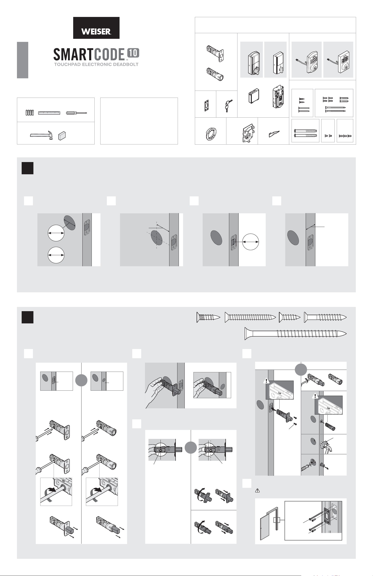
Prepare the door and check dimensions
1
If drilling a new door, use the supplied template and the complete
door drilling instructions available at www.weiserlock.com/doorprep.
Phillips head screwdriver
Weiser
USA: 1-800-677-5625
Canada: 1-800-501-9471
www.weiserlock.com
Strike
C
Adapter
Ring
D
Keys
E
A
B
Mounting
Plate
Tra di ti o na l
M
K L
G
Contemporar y
M
SmartKey
Too l
Tra di ti o na l
F F
Fasteners
03809
SL03031011
N
P
48654 64109
T
H
Q
S
Contemporar y
49191
U
R
V
Measure to conirm that the hole in
A
the door is either 21/8" (54 mm) or
11/2" (38 mm).
21/8"
54 mm
or
11/2"
38 mm
Note: Additional door preparation may be
required for doors with 11/2" (38 mm) holes.
Consult the deadbolt drilling instructions at
www.weiserlock.com/doorprep.
Install the latch and strike
2
Measure to conirm that the backset is
B C D
either 23/8" or 23/4" (60 or 70 mm).
23/8" or 23/4"
60 or 70 mm
backset
actual
size
Measure to conirm that the hole in
the door edge is 1" (25 mm).
1"
25 mm
NPSQR
Measure to conirm that the door is
between 13/8" and 2" (35 mm and
51 mm) thick.
13/8" – 2"
35 – 51 mm
Is the door edge chiseled? Which latch are you installing?
A D
YES NO
chiseled
Use latch “A”. If the
latch bolt is not already
extended, extend the
latch bolt as shown.
A
or
Use latch “B”. If the
latch bolt is not already
extended, extend the
latch bolt as shown.
not
chiseled
B
Hold the latch in front of the door hole, with the latch
B
face lush against the door edge.
A
Is the D-shaped hole centered in the door hole?
C
Latch “A” Latch “B”
B
A
YES NO
or
D-shaped hole D-shaped hole
No adjustment is required.
Proceed to next step.
Rotate latch face as
shown to extend latch.
A
Install strike on the door frame.
E
Make sure the hole in the door frame is drilled a
minimum of 1" (25 mm) deep.
N or P
(2x)
or
B
wood
block
1 / 4
Longer screws
install closest to
the door jamb.
B
S (2x)
Q or R (2x)
C
door frame
Page 2
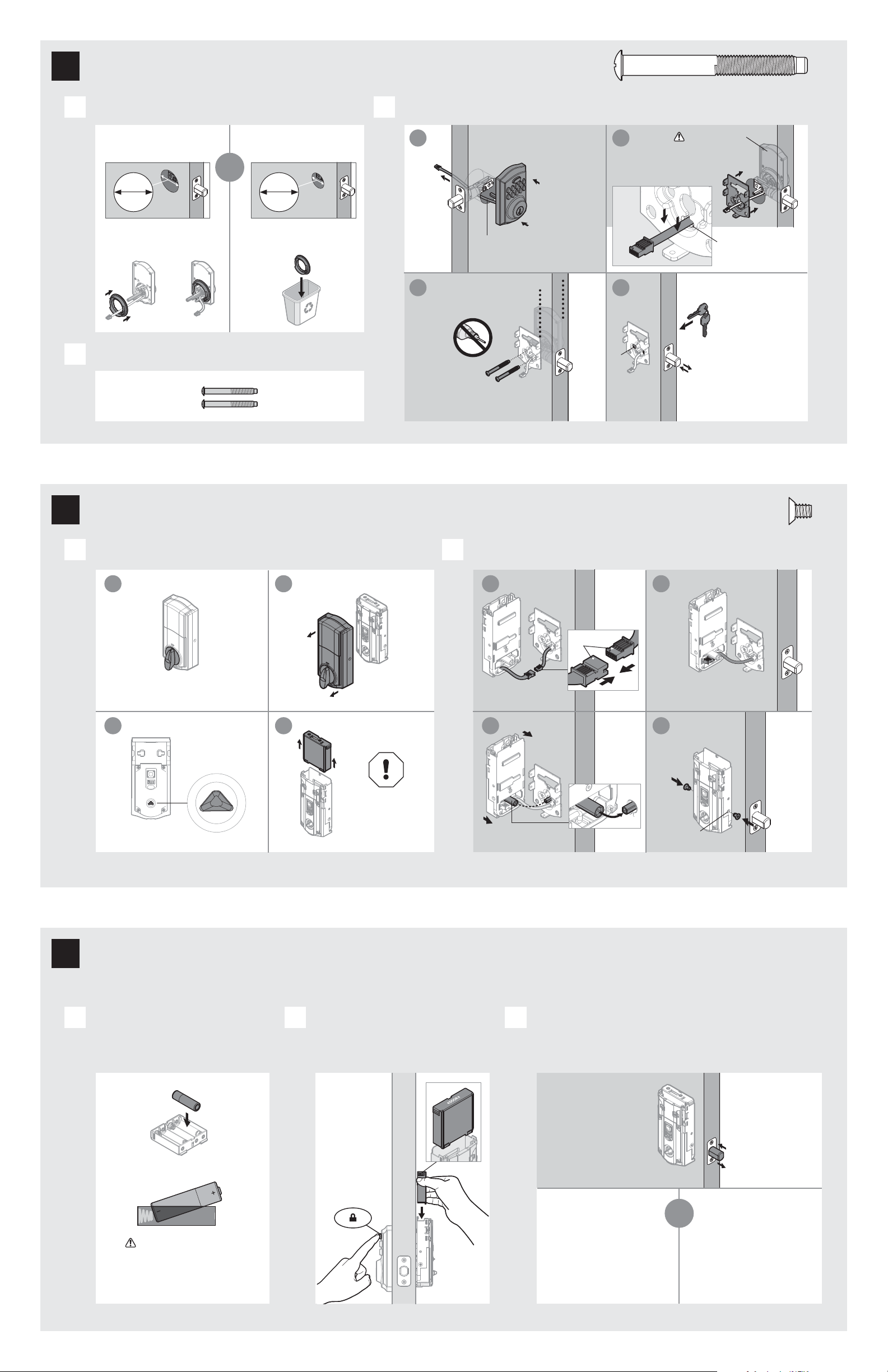
Install the exterior keypad
3
actual
size
T
What is the diameter of the hole in the door?
A
Diameter is 21/8"
(54 mm)
or
21/8"
54 mm
“D” is required for installation.
Install “D” on “F”.
F
D
Locate screws for step 3C and keep them within reach.
B
T
“D” is not needed for
installation. Discard “ D”.
Diameter is 11/2"
(38 mm)
11/2"
38 mm
D
Install exterior keypad and mounting plate.
C
a
Cable goes
underneath latch.
c
Keep parallel to
edge of door.
Tighten
screws evenly.
T (2x)
b
Support exterior
assembly during
mounting plate
installation.
G
F
Route cable through
center hole, then push
cable into b ottom hole.
d
E
Insert key and
test latch. If latch
does not extend or
T
retract smoothly,
adjust screws (T).
Remove key when
inished and make
sure the latch bolt
is fully extended.
Install the interior assembly
4
Remove battery cover and battery pack from interior assembly. Install interior assembly onto mounting plate.
A B
a
b
L
Make sure turnpiece is in
the vertical position.
c
L
d
Make sure
turnpiece shaft is
rotated as shown.
M
K
Do not install
batteries
until step 5.
L
a
L
Ensure tight cable
connection.
c
actual
size
U
b
align
Lay excess cable lat inside the
bottom of the interior housing.
d
U
(2x)
bottom
hole
Install the batteries and perform the door handing process
5
This step will teach your lock the orientation of your door and is crucial to lock operation.
Install 4 AA batteries in battery pack. Press and HOLD the Lock button
A B C
while installing battery pack.
Hold button until the latch bolt
starts moving on its own.
K
Ensure correct polarity.
For best results, use
new, non-rechargeable
Alkaline batterie s only.
Did the latch bolt retract and extend on its own
when the battery pack was installed?
YES NO
or
Door handing process
was successful! Proceed
to next step af ter latch
bolt stops moving.
Remove battery pack,
wait 15 seconds, then
attempt the process again.
Note: Latch
bolt will only
retract half way.
2 / 4
Page 3

Add user codes (16 max)
6
Programming Timeout
During programming, if no button is pre ssed for ive seconds, the system will time out (indicated by
three bee ps and a red lashing keypad), and you will need to restart the procedure.
Make sure the door is open. Press
A B C
the Program button once.
What lights and sounds does the lock produce?
D
Enter user code. A total of 16 user
codes may be programmed.
Each user code
must be a unique
code between 4
and 8 digits.
One green lash with one beep Three red lashes with three beeps
or
green
1x
Press Lock button once.
red
3x
Programming was successful. Programming was unsuccessful.
*Beeping sound will only be h eard if switch #3 (on the lock interior) is in the on positon. See “Switches and Status LED Colors” on page 4.
Mastercode
For enhanced security, a mastercode may be used when adding and deleting user codes. For more information about the mastercode,
download the Programming and Troubleshooting Guide on the SmartCode 10 page at www.weiserlock.com.
Test the lock (review normal operation)
7
Conirm that the code(s) added in previous step can unlock the door.
Make sure not to pause for more than 5 seconds during programming.
Make sure the user code is not a duplicate and that it is between 4 and 8 digits
duri ng your next a ttemp t. Make sure the lock has room for an add itional code. If
all user co de positions are illed, delete a cod e to make room for this one .
Locking the Door Unlocking the Door
Press Lock button once. Enter user co de.
Re-key the lock (if needed) and install the battery cover
8
Re-key the lock (if needed). Install the battery cover.
A B
a a
IMPORTANT:
Remove battery
pack before
re-keying.
K
b b
Re-key the lock
to work with your
existing key. See
the supplied
SmartKey Re-key
instructions for
more information.
c
Reinstall
battery
pack.
K
H
actual
size
V
M
V (3x)
3 / 4
Page 4

Reference Guide
SmartCode at a Glance
Exterior
Keypad
SmartKey
tool hole
Lock
button
Keyway
Interior (cover removed)
Back
panel
Program
button
Switches
Status
LED
Tur np ie ce
shaft
Note: When the cover is removed,
the turnpiece shaft can be used to
manually lock and unlock the door.
System Alerts
Alert Reason Solution
Keypad lashes red three
times with three beeps*.
Keypad lashes red 15 times
with 15 beeps*
Keypad lashes red with fast
beeping sound for three to
four seconds.
Keypad lashes green with
continuous beeping sound
for two seconds.
*Beep ing sound will only b e heard if switch #3 is on.
Switches and Status LED colors Troubleshooting
One incorrect code entered. Re-enter code.
No user code programmed. Program at least one user code.
Programming timeout after ive
seconds.
Unsuccessful programming.
Three incorrect codes entered
within one minute.
Low battery. Replace batteries.
Door jammed while attempting
to lock.
Attempt programming procedure again.
Re-enter code after 60 second keypad
lockout.
Manually re-lock door. If needed,
reposition strike.
Switches
On
O
Status
LED
1 2 3 4
Switch Function
Door lock status LED blinks every 6
1
seconds
Lock automatically re-locks door 30
2
seconds after unlocking. Disabled if no
codes are programmed.
3 Audio
4 Not used.
Color Lock Status
Blinking green Unlocked
Blinking amber Locked
Blinking red Low battery
Door handing process
Solid red
did not work properly.
See the online
Programing and
Troubleshooting Guide.
Deleting a single user code
Note: All codes may be deleted at once if the mastercode is enabled. For more information about the
mastercode, consult the online Programming an d Troubleshooting Guide.
1 Keep door open.
Press Program
button once.
2 Press Lock
button once.
3 Enter user code
to be deleted.
4 Press Lock
button once.
A complete Programming and Troubleshooting Guide is
available on the SmartCode 10 page at www.weiserlock.com.
Factory Reset
A factory re set will delete all codes associated with the lock.
1 Remove
battery pack.
2 Press and HOLD the Program
button while reinserting
the battery pack.
Keep holding the but ton for 30
seconds until the lock beeps
and the status LED lashes red.
Status
LED
5 Re-enter user code. 6 Press Lock
button once.
If no button is pressed for ive seconds, the system will time out, and
you will nee d to restar t the procedure.
If unsuccessful
Make sure to enter
the same valid code
in steps 3 and 5.
Tes t co de
While the door is
open, test the user
code to make sure
it no longer unlocks
the door.
Important Safeguards
1. Read all instructions in their entirety.
2. Familiarize yourself with all warning and caution statements.
3. Remind all family members of safety precautions.
4. Protect your user codes and mastercode.
5. Dispose of used batteries according to local laws and regulations.
CAUTION: Prevent unauthorized entry. Since anyone with access to the back panel
can change the user codes, you must restrict access to the back panel and routinely
check the user codes to ensure they have not been altered without your knowledge.
The use of a mastercode can help protect your system’s settings.
WARNING: This Manufacturer advises that no lock can provide complete security
by itself. This lock may be defeated by forcible or technical means, or evaded by
entry elsewhere on the property. No lock can substitute for caution, awareness of
your environment, and common sense. Builder’s hardware is available in multiple
performance grades to suit the application. In order to enhance security and reduce
risk, you should consult a qualiied locksmith or other security professional.
3 Press the Program button
once more. In 20 seconds,
when the LED lashes green
and you hear one beep, the
lock has been reset.
4 Perform th e door handing process again
to teach the lock the orientation of the
door and add user codes to your lock.
4 / 4
© 2016 Spectrum Brands, Inc.
 Loading...