

Page 1
61988 / 04
GED2150
ZWave
Parts in the box
ENGLISH
Installation and User Guide
Required tools
Ruler
Additional Tools (depending on application)
Hammer Wood block
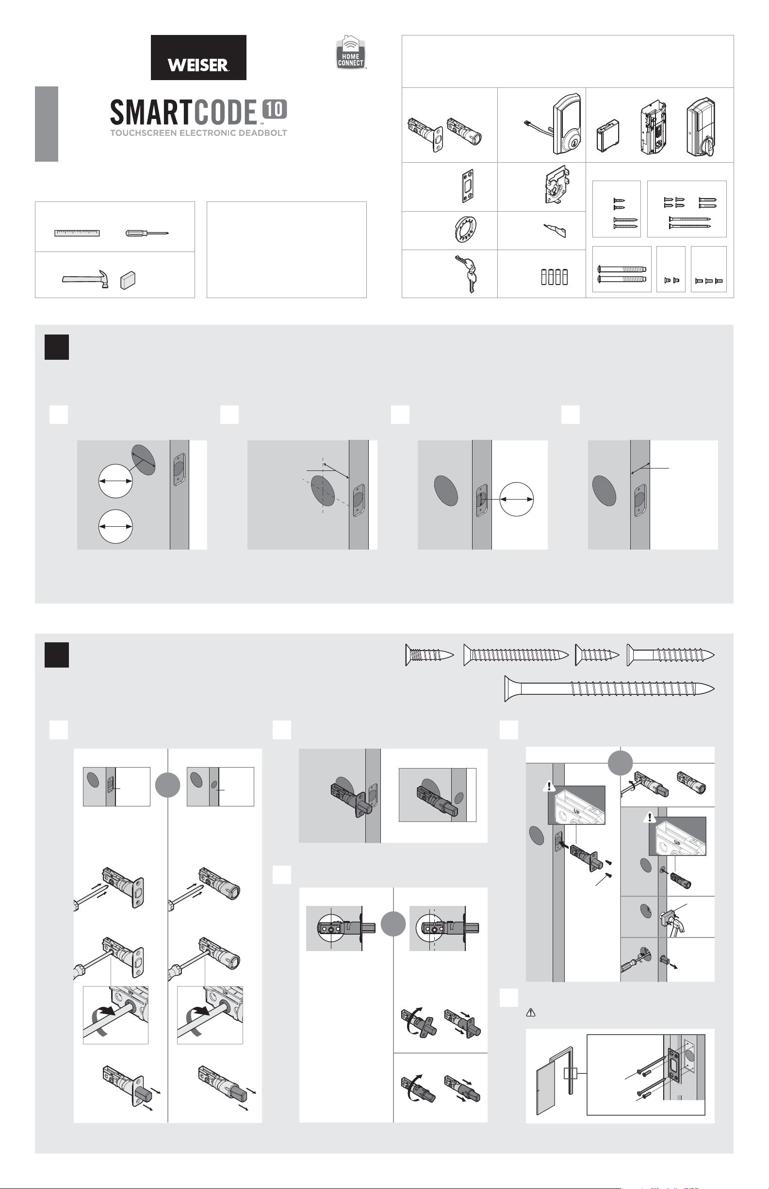
Prepare the door and check dimensions
1
If drilling a new door, use the supplied template and the complete
door drilling instructions available at www.weiserlock.com/doorprep.
Phillips head screwdriver
Weiser
1-800-501-9471
www.weiserlock.com
Latches
Strike
Adapter
Ring
Keys
Exterior
Tou ch sc re en
A B
Mounting
Plate
C
SmartKey
Too l
D
Batteries
E
Interior
Assembly
F
G
K L M
Fasteners
03809 SL03031011
N
P
Q
S
R
H
48654 49191 64109
J
T
U V
Measure to conirm that the hole in
A
the door is either 21/8" (54 mm) or
11/2" (38 mm).
21/8"
54 mm
or
11/2"
38 mm
Note: Additional door preparation may be
required for doors with 11/2" (38 mm) holes.
Consult the deadbolt drilling instructions at
www.weiserlock.com/doorprep.
Install the latch and strike
2
Measure to conirm that the backset is
B C D
either 23/8" or 23/4" (60 or 70 mm).
23/8" or 23/4"
60 or 70 mm
backset
actual
size
Measure to conirm that the hole in
the door edge is 1" (25 mm).
1"
25 mm
NPSQR
Measure to conirm that the door is
between 13/8" and 2" (35 mm and
51 mm) thick.
13/8" – 2"
35 – 51 mm
Is the door edge chiseled?
A B
YES
chiseled
Use latch “A”. If the
latch bolt is not already
extended, extend the
latch bolt as shown.
A
or
NO
not
chiseled
Use latch “B”. If the
latch bolt is not already
extended, extend the
latch bolt as shown.
B
face lush against the door edge.
A
Are the latch holes centered in the door hole?
C
YES
or
No adjustment is required.
Proceed to next step.
Rotate latch face as
shown to extend latch.
A
B
NO
Which latch are you installing?Hold the latch in front of the door hole, with the latch
D
Latch “A” Latch “B”
A
Install strike on the door frame.
E
Make sure the hole in the door frame is drilled a
minimum of 1" (25 mm) deep.
N or P
(2x)
or
B
wood
block
1 / 4
Longer screws
install closest to
the door jamb.
B
S (2x)
Q or R (2x)
C
door frame
Page 2
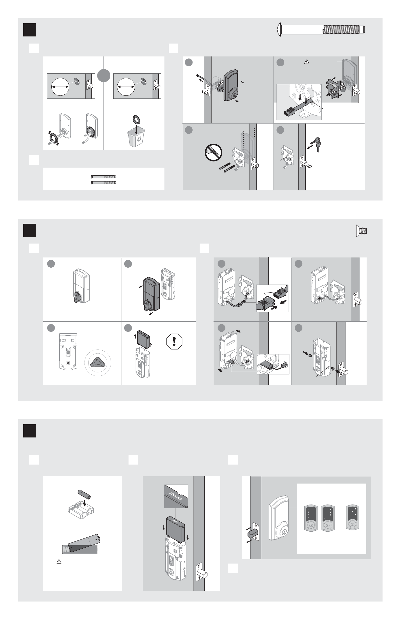
Install the exterior touchscreen
3
actual
size
T
What is the diameter of the hole in the door?
A
Diameter is 21/8"
(54 mm)
or
21/8"
54 mm
“D” is required for installation.
Install “D” on “F ”.
F
D
Locate screws for step 3C and keep them within reach.
B
T
“D” is not needed for
installation. Discard “D ”.
Diameter is 11/2"
(38 mm)
11/2"
38 mm
D
Install exterior touchscreen and mounting plate.
C
a
F
Cable goes
underneath latch.
c
Keep parallel to
edge of door.
Tighten
screws evenly.
T (2x)
b
Support exterior
assembly during
mounting plate
installation.
G
Route cable through
center hole, then push
cable into b ottom hole.
d
E
Insert key and
test latch. If latch
does not extend or
T
retract smoothly,
adjust screws (T).
Remove key when
inished and make
sure the latch bolt
is fully extended.
Install the interior assembly
4
Remove battery cover and battery pack from interior assembly. Install interior assembly onto mounting plate.
A B
a
b
L
Make sure turnpiece is in
the vertical position.
c
L
d
Make sure
turnpiece shaft is
rotated as shown.
M
K
Do not install batteries
until step 5.
Alarm will sound if
battery is installed
before cable is
L
connected.
a
L
Ensure tight cable
connection.
c
actual
size
U
b
align
Lay excess cable lat inside the
bottom of the interior housing.
d
U
(2x)
bottom
hole
Install the batteries and perform the door handing process
5
This step will teach your lock the orientation of your door and is crucial to lock operation.
Install 4 AA batteries in battery pack. Make sure the door is open, and
A B C
insert the battery pack.
J
K
K
Ensure correct polarity.
For best results, use
new, non-rechargeable
Alkaline batteries only.
After a few seconds, the latch bolt will retract and extend on
its own to learn the orientation of the door. This is called the
door handing process, and it is crucial to lock operation.
Once the door handing process
is complete, the touchscreen
will indicate success or failure:
Success:
lashing checkmark
symbol and single
column of digits
D
If the touchscreen indicates a failure, attempt this procedure again.
If the door handing process is still unsuccessful after a second
attempt, consult the Programming and Troubleshooting Guide on
the SmartCode 10 Touchscreen page at www.weiserlock.com.
Fail ure :
lashing
“X” pattern
2 / 4
Page 3

Pair the lock with your smart home system
6
Initiate the pairing process at your smart
A B C
home controller. Refer to your smart home
system instructions for more information.
When prompted by your smart home
system to initiate pairing at the lock, press
button “A” on the lock interior one time.
button “A”
Add user codes (30 maximum)
7
It is recommended that you
add and delete all use r codes
through your smart home
control system. If your system
does not allow this, codes may
be added directly to the lock as
shown here.
Programming Timeout
During programming, if the
screen is not pressed for 20
seconds, the system will time
out (indicated by three beeps
and the “X” pattern lashing
three time s), and you will n eed to
restart the procedure.
Make sure the door is
A B C D
open. Press the Program
button once.
Press checkmark
symbol once.
If the pairing process is successful, re-name
the lock in your system (if applicable).
If the pairing process is unsuccessful, follow your smart
D
home system's instructions to remove the device from
any other network.
Perform steps 6A6C again.
If pairing is still unsuccessful, consult the Programming
and Troubleshooting Guide on the SmartCode 10
Touchscreen page of online at www.weiserlock.com.
Enter user code. A total
of 30 user codes may
be programmed.
Each user code must b e a
unique code between 4 and
8 digits, depending on your
smart home system.
Press lock symbol once.
What digits and sounds did the lock produce?
E
Mastercode
For enhanced security,
a mastercode may
be used when adding
and deleting user
codes. For more
information about the
mastercode, download
the Programming and
Troubleshooting Guide
on the SmartCode 10
Touchscreen page at
www.weiserlock.com.
*Beeping sound will only be heard if switch #3 (on the lock interior) is in the on positon. See “Switches and Status LED Colors” on page 4.
Test the lock (review normal operation)
8
Conirm that the code(s) added in previous step can unlock the door.
Checkmark symbol with one beep
“X” pattern with three beeps
or
1x 3x
Programming was successful. Programming was unsuccessful.
Make sure the user code is not a duplicate and that it is between
4 and 8 digits during your next attempt.
Make sure the l ock has room for an add itional code. If al l user code
positio ns are illed, del ete a code to make room for thi s one.
Activating the Screen Locking the Door Unlocking the Door SecureScreen™
Option 1
Touch screen with
palm or back of
hand until digits
illuminate.
Re-key the lock (if needed) and install the battery cover
9
Re-key the lock (if needed). Install the battery cover.
A B
a a
IMPORTANT:
Remove battery
pack before
re-keying.
Option 2
Touch lower left
area of screen
(where checkmark
is located) until
digits illuminate.
K
Option 3
Touch screen
with three or
more ingers until
digits illuminate.
b b
Re-key the lock
to work with your
existing key. See
the supplied
SmartKey Re-key
instructions for
more information.
1. Activate the screen.
2. Press Lock symbol.
Note: If no user codes are
programmed, the door cannot
be locked via touchscreen.
c
Reinstall
battery
pack.
H
1. Activate the screen.
2. If SecureScreen™ is enabled, touch
the random digits that appear.
3. Enter user code.
If you pres s the wrong digit whi le entering
a user cod e, you can press th e Lock symbol
once to cle ar the digits ente red previously a nd
immedi ately restart th e code entry pro cess.
K
M
SecureScreen is an added-security feature
that displays random digits before you enter
a user code to unlock the door. This feature
ensures that there are ingerprints on all
digits so that codes cannot be identiied by
examining the touchscreen for inger prints.
If desir ed, this feature
can be dis abled by
turning s witch #4 to
the o po sition. See
“Switches” on page 4.
actual
size
V
V (3x)
3 / 4
Page 4

Reference Guide
SmartCode at a Glance System Alerts
Exterior
Tou ch sc re en
Checkmark
symbol
SmartKey
tool hole
Lock
symbol
Keyway
Switches and Status LED Colors
Switches
Interior (cover removed)
Back
panel
Button “A”
Program
button
Status
LED
Note: When the cover is removed,
the turnpiece shaft can be used to
manually lock and unlock the door.
Button “B”
Switches
Tur np ie ce
shaft
Display Alert Reason Solution
“X” pattern lashes one time
with one beep*.
“X” pattern lashes three
times with three beeps*.
“X” pattern lashes 15 times
with 15 beeps*
Checkmark and lock symbols
lash simultaneously ive
times with long continuous
beep*.
Checkmark and lock symbols
alternate lashing ive times
with long continuous beep*.
N/A Lock beeps continuously.
*Beep ing sound will only b e heard if switch #3 is on.
One incorrect code entered. Re-enter code.
No user code programmed. Program at least one user code.
Programming timeout after 20
seconds.
Unsuccessful programming.
Three incorrect codes entered
within one minute.
Low battery. Replace batteries.
Door jammed while attempting
to lock.
Interior assembly is
disconnected from exterior.
Attempt programming procedure again.
Re-enter code after 60 second
touchscreen lockout.
Manually re-lock door. If needed,
reposition strike.
Remove battery pack, reconnect the interior
to the exterior, then replace battery pack.
Manual Door Handing
If needed, the door handing process can be initiated manually.
This is useful if the lock is being moved to a di erent door.
On
O
Status
LED
1 Remove
battery pack.
1 2 3 4
Switch Function
1 Door lock status LED blinks every 6 seconds
Lock automatically re-locks door 30 seconds after
2
unlocking. Disabled if no codes are programmed.
3 Audio
SecureScreen feature displays random digits to be
pressed before entering user code. This added-
4
security feature ensures that there are ingerprints
on all digits so that codes cannot be identiied by
examining the touchscreen for ingerprints.
Color Lock Status
Blinking green Unlocked
Blinking amber Locked
Blinking red Low battery
3 Press the Program
button once more.
Deleting a single user code Factory Reset
Note: All codes may be deleted at once if the mastercode is enabled. For more information about the
mastercode, consult the online Programming and Troubleshooting Guide.
1 Keep door open.
Press Program
button once.
2 Press Checkmark
symbol once.
3 Press Lock
symbol once.
4 Enter user code
to be deleted.
A factory re set will delete all code s associated with the lock, and it will
remove it from your smart home system.
1 Remove
battery pack.
2 Press and HOLD the Program
button while reinserting the
battery pack.
Release but ton once bat tery
pack is installed . The status LED
will lash red and green.
4 The latch bolt
will extend and
retract to learn
the orientation
of the door.
Success
If the touc hscreen indic ates a failure, se e the
online P rogramming and Troub leshooting Gu ide.
2 Press and HOLD the Program
button while reinserting
the battery pack.
Keep holding the button for 30
seconds until the lock beeps
and the status LED lashes red.
Status
LED
Fai lure
Status
LED
5 Press Lock
symbol once.
6 Re-enter user
code.
If the screen is not pressed for 20 seconds, the system will time out,
and you will need to restart the procedure.
7 Press Lock
symbol once.
If unsuccessful
Make sure to enter the same
valid code in steps 4 and 6 .
Tes t co de
While the door is open, test the
user code to make sure it no
longer unlocks the door.
Network Information
Adding the lock to the network
During th e pairing proce ss, press butt on “A” on the lock
interior once.
ZWave System Notes
This prod uct is a securit y enabled Z-wave produc t and must be use d with a Security Ena bled ZWave controller to b e fully
utilized . ZWave is a “Wi reless mesh ne twork,” and resul ts may vary based o n building cons truction and co mmunication pa th,
with 35 fee t+ being typica l installed di stance from smar t home controll er. It may be necessa ry to install add itional ZWave
beamin g capable device s that can serve a s repeaters to enh ance the communi cation path bet ween the lock and c ontroller for
a more robu st ZWave netwo rk.
To assure intero perability, eac h ZWave produc t must pass a strin gent conforman ce test to assure that i t meets the ZWave
standa rd for complete com pliance with all oth er devices and co ntrols. The ZWave ident ity mark assures c onsumers,
integrat ors, dealers a nd manufacture rs that their prod ucts will relia bly perform with a ny other ZWave device. And , regardless
of the vend or, always powe red nodes may ac t as a repeater for Kwiks et/Weiser/Ba ldwin product s.
ZWave Conigu ration and Asso ciation Paramete rs are available on t he SmartCode 1 0 Touchscr een page at weise rlock.com.
Removing the lock from the network
Follow your sm art home system’s in structions to rem ove
the lock from the net work. Whe n prompte d by the
system, p ress button A” on the lo ck interior once .
3 Press the Program button
once more. The status
LED will lash green and
red several times.
4 After a few seconds, the lock will
initiate the door handing process, and
the latch bolt will extend and retract
to learn the orientation of the door.
Important Safeguards
1. Read all instructions in their entirety.
2. Familiarize yourself with all warning and caution statements.
3. Remind all family members of safety precautions.
4. Protect your user codes and mastercode.
5. Dispose of used batteries according to local laws and regulations.
CAUTION: Prevent unauthorized entry. Since anyone with access to the back panel
can change the user codes, you must restrict access to the back panel and routinely
check the user codes to ensure they have not been altered without your knowledge.
The use of a mastercode can help protect your system’s settings.
WARNING: This Manufacturer advises that no lock can provide complete security
by itself. This lock may be defeated by forcible or technical means, or evaded by
entry elsewhere on the property. No lock can substitute for caution, awareness of
your environment, and common sense. Builder’s hardware is available in multiple
performance grades to suit the application. In order to enhance security and reduce
risk, you should consult a qualiied locksmith or other security professional.
4 / 4
© 2015 Spectrum Brands, Inc.
 Loading...