

Page 1

Touchpad Electronic Deadbolt
Installation & Learning Instructions
English
Electronics Division
A Black & Decker Company
©2009 Weiser. Printed in the USA
Part No: 41635-01
19701 DaVinci
Lake Forest, CA 92610
1-800-343-9652 USA
1-800-501-9471 CANADÁ
www.powerbolt.com
Owner’s Manual
Français
Español
Page 2

Table of Contents
Enclosed Pieces Page 1
1 Door Preparation Page 2
2 Deadbolt Latch Installation Page 2
3 Strike Installation Page 3
4 Touchpad Electronic Deadbolt Installation Page 4
5 Programming Instructions Page 6
6 Proper Operation of Touchpad Electronic Deadbolt Page 7
Notes and Warranty Page 8
Troubleshooting Tips Page 9
This product is covered by one or more of the following patents or patents pending: 5123683 5317889 5335525 5335950 5441318
5452928 5482335 5490700 5496082 5513509 5513510 5529351 5540070 5570912 5662365 5761937 5810402 5816629 5857365
6058746 6128933 6151934 6398465 6401932 6412319 6443504 6532629 6536812 6568727 6598440 6662606 6695365 6702340
6745602 6828519 6860131 6860529 6862909 6871520 6880871 6948748 6951123 6959569 6971513 6973813 7007528 7100408
7104098 7114357 7117701 7152891 7156432 7162901 7213429 7234331 7308811 RE38693 D344011 D347564 D348602 D348821
D352888 D361488 D361489 D361706 D363872 D373063 D373523 D400777 D407292 D431443 D435423 D436933 D437216
D437771 D443194 D443808 D446122 D447927 D452131 D453897 D453898 D453899 D454049 D458839 D461700 D463968
D464565 D464877 D465989 D468636 D472794 D473780 D514921 D524630 D525512 D525516 D540140 D540147 D541621
D542115 D545169 D547830 4892341 4893854 4921290 4966021 4974884 5169184 5257837 5316355 5364138 5411303 5433497
5562314 6419288 6612627 7178842 D511671 D519020
Page 3
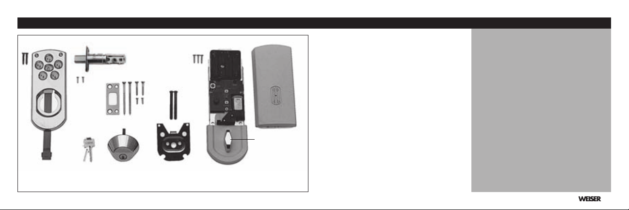
Enclosed Pieces
A
B
H
C
T-TURN
A
B
C
I
D
E
F
G
H
I
Pieces
Touchpad
Latch
Strike
Keys
Deadbolt
Mounting Plate
Power Strip
Power Board
Access Cover
Important Notes:
Use the components from this
package, make no substitutions.
Consult local building codes for
requirements in your area.
Read all instructions and lay out
parts as shown.
Under normal use it is recommended to replace the batteries in
the Power Board once a year.
G
D E F
1
Page 4
Replacement Installation
UP
1
Remove all old lock
components.
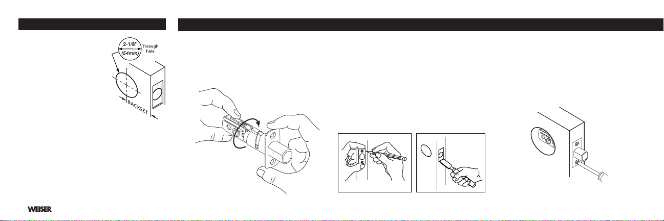
2
Use the enclosed template
to verify the following:
•
Deadbolt face hole needs to
be 2-1/8” (54mm) diameter.
•
Backset – Distance from
edge of door to center of
lock (2-3/8 or 2-3/4”).
•
Location to drill the small starter holes for
inside and outside trims.
•
Make any necessary modifications.
First-time Installation
Follow instructions on enclosed template.
2
2. Deadbolt Latch Installation (Piece B)1. Door Preparation
To Adjust Backset:
Rotate to a 2-3/4” (70mm)
position, if required.
Preparation for latch with Face Plate
1
Keeping edges parallel to the face of the door,
outline face plate and remove deadbolt latch
(see illustration below left).
2
Chisel outline of face plate until it is flush with
door edge, 5/32” (4mm) deep (see illustration
below right).
Install Latch
For latch with face plate:
With bolt extended, insert deadbolt latch in
1
edge hole. Be sure to keep the word "UP" at
top. Secure with two 5/8” wood screws.
Page 5
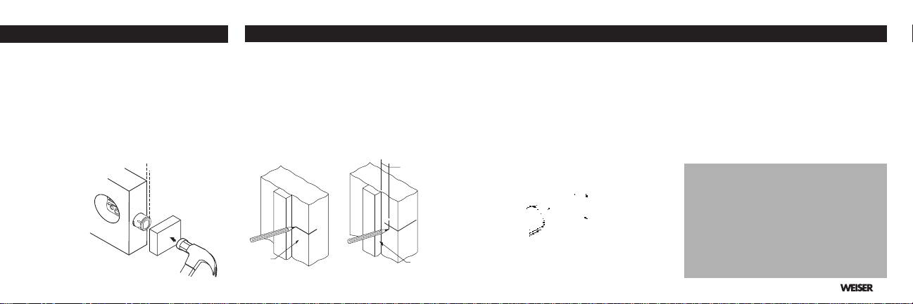
U P
Door
Jamb
1/2 of door
thickness
Door
Stop
For Drive-In latch:
1
With bolt retracted, insert deadbolt latch into
edge hole keeping flat edge of bolt parallel to
the edge of door. Be sure to keep the word
"UP" at top.
2
Using a wood block, tap with hammer until
surface of collar is flush with door edge
Re-extend bolt.
First-time Installation
1
Draw a horizontal centerline across the door
jamb, the same distance from floor as is the
centerline of deadbolt latch.
Measure back from door stop, 1/2 the
2
distance of the door thickness and draw a
vertical centerline. At crosspoint, drill a 1-1/8”
diameter (28.5mm) hole,1-1/4” (29mm) deep,
in the door jamb.
Center strike over hole and trace around
3
strike. Chisel out door frame until strike is
flush.
Position strike with large holes toward door
4
stop. Pre-drill large holes 3” (76mm) deep.
Install strike
1
Install 3” (76mm) screws in large strike holes
and install remaining 5/8” wood screws in
smaller holes.
2
Close door and ensure bolt extends and
retracts freely.
Important Note:
Deadbolt latch must enter strike
with no resistance or the Powerbolt Touchpad Electronic Deadbolt
will not work properly.
3
Page 6
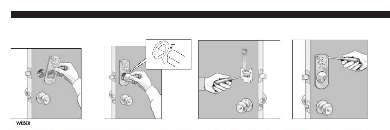
4. Touchpad Electronic Deadbolt Installation
Round
Crank
1 2 3
With bolt of latch in the extended position,
place Touchpad A on outside of door and
place power strip G through door over top
of latch B. Note: Do not remove backing
from Touchpad.
4
With key removed, place deadbolt E against
Touchpad A with round of torque blade at top
to enter through crank of latch B.
Attach deadbolt with 2 large black bolts
through mounting plate F as shown. Power
strip G should extend out.
4
Line Touchpad A up with small holes from
template and attach with two 1” oval head
screws. Do not over-tighten screws.
Page 7
5 6 7
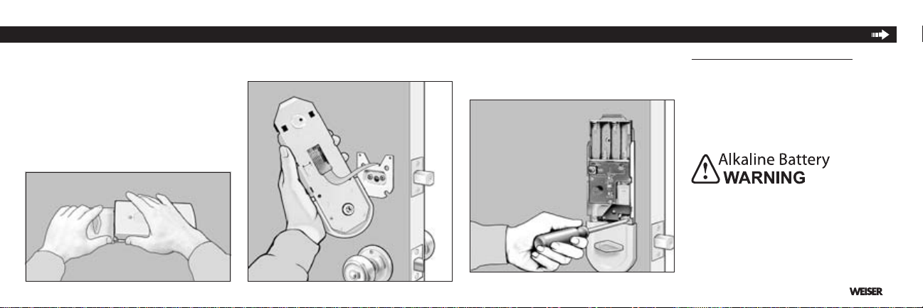
Remove access cover I from Power Board H.
Hold as shown in photo and twist or pull up
on cover.
Feed power strip G through large square hole
of Power Board H and plug into the 6 prongs.
Line Power Board H up to the 3 small holes
drilled from the template. Verify that torque
blade engages with the T-turn and attach
power board with 3 chrome-colored screws.
8
Install 4 new AA Alkaline batteries (not
included in package). Battery positions shown
on battery case. A series of quick beeps will
sound when batteries make complete contact.
Low Battery Indicator Light on the Power
Board will be lit when the batteries need to be
replaced.
Do not dispose of in fire, recharge, put in
backwards, disassemble, mix with used or
other battery types. May explode or leak and
cause personal injury.
5
Page 8
4. Touchpad Electronic Deadbolt Installation 5. Programming Instructions
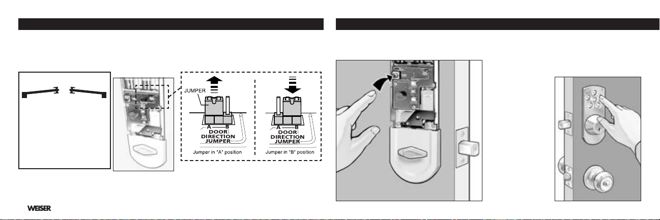
Retract deadbolt latch B with T-turn. Press the lock button on Touchpad A. If motor runs but
9
latch does not extend: Door handing needs to be changed. To change door handing, remove
jumper (located in the upper right corner of the circuit board) from position "A" and plug it into
position "B". See illustrations.
Left hand
Door
Exterior
Right hand
Door
From Exterior:
If hinge is on the left, you
•
have a left hand door.
If hinge on the right, you
•
have a right hand door.
Verify key works in deadbolt E.
10
Note: When manually locking or unlocking the deadbolt by turning the key or the T-turn:
The motion will be rm — this resistance is normal.
6
Push program button on Power Board H once. 1
Enter desired 4 to 8 digit code by pressing
2
numbers on outer Touchpad A. Press the
Lock button on Touchpad to set your code.
You will hear a 2-second long beep when your
3
code is accepted.
If unit does not
beep — too much
time has elapsed
between steps
1 and 2. Repeat
steps 1 and 2
faster.
Page 9
Enter your number to verify that it retracts
4
the latch B.
To Enter Second Code
Push program button twice, then repeat steps
2-4.
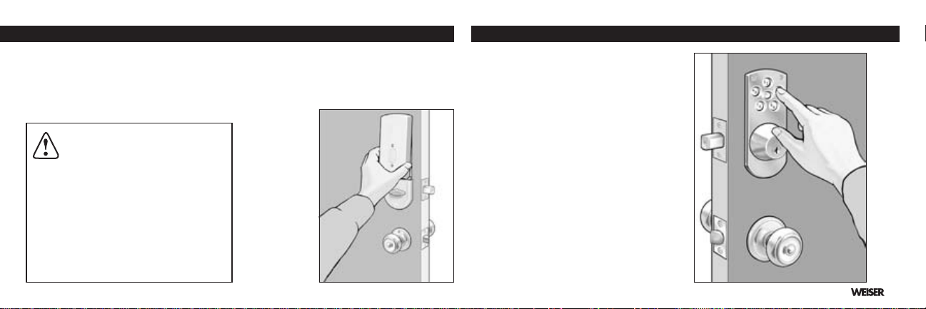
CAUTION: Prevent unauthorized
entry. This lock can be opened
using two different codes that are randomly
set at the factory. Upon installation and
set-up, replace both of these codes with
your own. Since anyone with access to the
power board can change these codes, you
must restrict access to the power board
and routinely check both codes to assure
they have not been altered without your
knowledge.
5
Snap access cover I onto power board H.
Align cover to top of power board and press
down at the bottom of the cover (see illustration below). To coordinate with your home
decorating scheme, the access cover may
be painted to
match your
door.
1
Push the Lock button on outside touch pad to
extend latch bolt 1” which locks the door when
you leave.
2
Enter your desired personal code to retract
the latch bolt completely which unlocks the
door when you return home.
3
The T-turn on the inside of the door is used to
extend (lock) or retract (unlock) the latch bolt
when you are inside.
4
Using the key from the outside will also extend
(lock) or retract (unlock) the latch bolt.
5
This Touchpad Electronic Deadbolt should be
accompanied by a Weiser Knobset, Leverset,
or Handleset.
7
Page 10

Important — Please Read Warranty Manufacture's note.
Under normal use it is recommended to
replace the batteries once a year. When
batteries are low, it will take longer to retract
the bolt. Batteries should be changed immediately!
Lower latch must hold shut allowing deadbolt
latch to enter strike freely with no restrictions.
If door is misaligned, make necessary adjustment to deadbolt strike location and/or hole
in door jamb to allow the deadbolt latch to
retract and extend freely.
Reprogramming of codes should not be
necessary after changing batteries.
If required, key can be used to retract
deadbolt.
If interior trim is exposed to extreme cold
temperatures, the batteries will not operate.
This is typical of all batteries and not a malfunction of the lock.
8
Weiser Brilliance™
•
Full Lifetime Finish Warranty
Full Lifetime Mechanical Warranty
•
One Year Limited Electrical Warranty
•
This warranty states all mechanical lock
parts will be free from defects in material and
workmanship, including deterioration over
time, of the Brilliance finish on the exterior
lock components while the original purchaser
owns the lock.
All electrical components are covered by a
One Year Limited Warranty.
Our warranty excludes locks that have been
damaged by installation contrary to our writ-
ten instructions or modified with non-Weiser
components. It also excludes incidental
or consequential damages. (Some states
do not allow the exclusion or limitation of
incidental damages so this exclusion may
not apply to you.)
To register a warranty claim, please return
the product, freight prepaid to: Attn: Customer
Service, Weiser, 19701 DaVinci Lake Forest,
CA 92610. Weiser will repair or replace the
lock or refund the purchase price
(if it is not practical to repair or replace). You
will be responsible for the removal of the old
lock and the installation of the new one.
This Warranty provides you with specific legal
rights and you may also have other rights
which vary from state to state.
This Manufacturer advises that no lock can
provide complete security by itself. This lock
may be defeated by forcible or technical
means, or evaded by entry elsewhere on the
property. No lock can substitute for caution,
awareness of your environment, and common sense. Builder’s hardware is available
in multiple performance grades to suit the
application. In order to enhance security and
reduce risk, you should consult a qualified
locksmith or other security professional.
Page 11

Troubleshooting Tips
If Electronics Are Not Working —
Check the Following:
Are your batteries good? Is the power strip
plugged in properly? (See step 4.6)
Are the batteries installed correctly and making full contact? (See step 4.8) You should
hear a series of quick beeps when batteries
are installed correctly and making full contact.
Handing of Your Door
If the bolt does not extend when lock button is
pressed, check the handing of your door (See
Step 4.9)
Preset Factory Codes
This lock will maintain two different codes.
Two random codes are preset by the factory
for testing. It is recommended that you enter
two new security codes to cancel out the
preset codes. (See step 5).
Problems with Setting your Security Codes
— Check the Following:
You will hear a 2 second beep when your
codes are accepted. (See step 5.1-3).
If the unit does not beep — too much time has
elapsed between steps 1 & 2. Repeat these
steps faster.
Note: You have approximately 3 seconds
between step 1 & 2 for your codes to be
accepted. Please note the next statement.
Unauthorized Code Warning:
For your added security, a warning tone will
sound for 15 seconds if an incorrect security
code is entered three times consecutively. The
Touchpad will not operate for 1 minute.
Note: If several attempts were needed to
set your security codes — you may have
activated the warning sound. Wait 1 minute
for the unit to be operational again.
Important Note:
Manual locking or unlocking the
deadbolt by turning the key or the T-
turn — the motion will be firm. This
resistance is normal for this lock.
For assistance call
1-800-343-9652 USA
1-800-501-9471 CANADA
or visit www.powerbolt.com
9
Page 12

Mode de pose et apprentissage de
Verrou à pêne dormant électronique à pavé tactile
Division d'électronique
Une compagnie de Black & Decker
©2009 Weiser.
Numéro de la pièce: 41635-01
3980 N. Fraser Way
Burnaby (C.-B.) V5J 5K5
1-800-501-9471
www.powerbolt.com
Manuel du propriétaire
Page 13

Table des matières
Pièces incluses Page 1
1 Préparation de la porte Page 2
2 Pose du pêne dormant Page 2
3 Pose de la gâche Page 3
4 Pose du Verrou à pêne dormant électronique à pavé tactile Page 4
5 Directives de programmation Page 6
6 Fonctionnement du Berrou à pêne domant électronique à pavé tactile Page 7
Notes et Garantie. Page 8
Conseils de dépannage Page 9
Page 14

Pièces incluses
A
G
1
B
C
D E F
Pièces
Pavé tactile
A
Pêne domant
B
Gâche
C
H
TAQUET
I
Clefs
D
Verrou a pêne dormant
E
Plaque de montage
F
Bande électrique
G
Tableau de commande
H
Covercle d'accès
I
Remarques importantes:
Utilisez les pièces comprises dans
cet emballage, sans y substituer
d'autres pièces.
Consultez les codes de bâtiment
locaux afin de satisfaire aux règlements de votre région.
Lisez toutes les instructions et
étalez les pièces selon l'illustration.
Sous usage normal, il est recommandé de changer les piles du
tableau de commande une fois par
an.
Page 15

1. Préparation de la porte 2. Pose du pêne dormant (Pièce B)
UP
Pose de surrure de remplacement
1
Retirez toutes les composantes de la vieille serrure.
Utilisez le gabarit ci-joint pour
2
vérifier les mesures suivantes:
Le tou transversal destiné au
•
verrou à pêne dormant doit
avoir un diamètre de 2-1/8 po
(54 mm).
Écartement - Distance du bord
•
de la porte jusqu'au centre de
la serrure (2-3/8 à 2-3/4 po).
•
Endroit où percer les petits trous d'amorçage des
garnitures intérieure et extérieure.
•
Effectuez les modifications nécessaires.
Pour ajuster l'écartement:
Tournez jusqu'à une
position de 2-3/4 po
(70mm), s'il y a lieu.
Pose de surrure neuve
Suivez les instructions du gabarit ci-joint.
Préparation pour un verrou avec un
plaque de face
1
En maimtenant les bords parallèles à la face
de la porte, tracez le contour de la plaque
de face et retirez le pêne dormant (voir
l'illustration ci-dessous à gauche).
2
Mortaisez le contour de la plaque de face à
une profoundeur de 5/32 po (4mm), jusqu'à
ce qu'elle soit au ras du bord de la porte (voir
l'illustration ci-dessous à droite).
Installez le verrou
Pour le verrou avec un plaque de face.
Avec le pêne étant prolongé, insérez le
1
pêne dormant dans le trou du bord de porte.
Soyez sûr de garder le mot (UP) au dessus
du verrou. Fixez-le à l'aide de deux vis à bois
de 5/8 po.
2
Page 16

2. (suite)
U P
Chambranle
de porte.
1/2
d'épaisseur
de porte
Arrêt de porte
Pour verrou rond
1
Le boulon étant rétracté, insérez le péne
dormant dans le trou du bord de porte en
maintenant le côte plat du verrou parallèle
à la face de la porte. Soyez sûr de garder le
mot (UP) au dessus du verrou.
2
À l'aide d'un bloc de bois, martelez jusqu'à
ce que la surface du col soit au ras du bord
de la porte. Détendez le pêne dormant.
3. Pose de la gâche (Pièce C)
Pose de serrure neuve
1
Tracez une ligne centrale horizontale à travers le
chambranle de porte, la même distance du plancher
qu'est la ligne centrale du verrou.
Mesurez à partir de l'arrêt de porte, 1/2 la distance
2
de l'épaisseur de porte et dessinez une ligne centrale verticale. Là où les lignes croisent, percez un
trou d'un diamètre de 1-1/8 po (28,5 mm) et d'une
profondeur de 1-1/4 po (29 mm) dans le chambranle
de porte.
Centrez la gâche sur le trou et
3
tracez son contour. Mortaisez
le chambranle de porte pour
permettre à la gâche de s'ajuster
au ras du chambranle.
4
Placez la gâche, les gros trous
ver le butoir de porte. Percez les
gros trous à une profondeur de 3
po (76 mm).
Installez la gâche
1
Posez des vis de 3 po (76 mm) dans les gros
trous de la gâche et posez les vis à bois de
5/8 po qui restent dans les petits trous.
Fermez la porte et assurez-vous que le pêne
2
dormant peut s'étendre et rentrer librement.
3
Remarque importante:
Le pêne dormant doit pouvoir rentrer
dans la gâche sans résistance, faute
de quoi le Verrou à pêne dormant
électronique à pavé tactile Powerbolt
ne fonctionnera pas correctement.
Page 17

4. Pose du Verrou à pêne dormant électronique à pavé tactile
Rond
Manivelle
1
Prolongez le boulon du verrou. Placez le
pavé tactile A sur l'extérieur de la porte et faites
passer la bande électrique G à travers la porte
au-dessus du pêne dormant B.
Remarque: Ne retirez pas la doublure du
pavé tactile.
En vous assurant que la clef n'est pas dans
2
la serrure, placez le verrou à pêne dormant E
contre le pavé tactile A,
de torque au dessus pour entrer par la manivelle
du
pêne dormant B.
avec le rond de la lame
Fixez le verrou à pêne dormant à l'aide de 2
3
gros boulons noirs en leur faisant traverser la
plaque de montage F selon l'illustration. La
bande électrique G devrait être étendue vers
l'extérieur.
Alignez le pavé tactile A avec les petits trous
4
du gabarit et fixez-le à l'aide de deux vis à
tête ovale de 1 pouce. Ne resserrez pas trop
les vis.
4
Page 18

0ILE!LCALINE
4. Pose du Verrou à pêne dormant électronique à pavé tactile (suite)
5 6 7
Détachez le couvercle d'accès I du tableau
de commande H en le tordant ou en tirant
dessus selon l'illustration ci-dessous.
5
Faites passer la bande électrique G par le
gros trou carré du tableau de commande H et
branchez-la dans les 6 broches.
Centrez le tableau de commande H sur les
3 petits trous percés à partir du gabarit.
Assurez-vous que le taquet s'engage dans
la lame de torque et fixez le tableau de commande à l'aide de 3 vis chromées.
8
Installez 4 piles alcalines AA neuves
(non comprises dans l'emballage). Respectez
la position de piles indiquée sur le boîtier.
Une séries de bips rapides se fera entendre
lorsqu'il se produira un contact complet des
piles.
L'indicateur de piles faibles du tableau de
commande s'allumera lorsque les piles auront
besoin d'être changée.
Ne pas incinérer, recharger, installer à
l'envers, démonter, utiliser avec des piles
usagées ou d'autres types de piles. Cela
présente des risques d'explosion ou de fuíte,
ainsi que des risques de blessures.
Page 19

9
Retrez le pêne dormant B à l'aide du taquet. Appuyez sur le bouton de verrouillage du pavé
tactile A. Si le moteur tourne mais que le pêne dormant ne s'étend pas, la main de la porte doit
être changée. Pour changer la main de la porte, enlevez l’interrupteur (jumper) de la position "A"
et branchez-l’à la position "B". (Voir l'ilustration.)
Porte
gauche
De l'extérieur:
Si la charnière est du côte
•
gauche de la porte, la
porte est àmain gauche.
Si la charnière est du côte
•
droit de la porte, la porte
est àmain droit.
Assurez-vous que la clef fonctionne dans le verrou à pêne dormant E.
10
Remarque: Lorqu'on verrouille ou qu'on déverrouille le verrou à pêne dormant à la main
en tournant la clef ou le taquet, il est normal de sentir une certaine résitance.
Exterior
Porte
droite
Pressez une fois sur le bouton de programma-
1 2
tion du tableau de commande H.
Entrez el code désiré, de 4 à 8 chiffres, en
appuyant sur les chiffres du pavé tactile A,
extérieur. Pressez le bouton de verrouillage
du pavé tactile pour fixer votre code.
3
Vous entendez un
bip de 2 secondes
lorsque votre code
sera accepté. Si
l'unité n'ément
pas de bip, il
s'est écoulé trop
de temps entre
les étapes 1 et
2. Refaites plus
rapidement les
étapes 1 et 2.
6
Page 20

5. Directives de programmation (suite) 6. Fonctionnement du Verrou à pêne dormant électronique à pavé tactile
Entrez votre numéro pour vous assurer qu'il
4
fait rentrer le pêne dormant B.
Pour entrer un second code
Pressez le bouton de programmation deux
fois, puis répétez les étapes 2 à 4.
AVERTISSEMENT: Prévient
l’entrée par infraction. Cette
serrure peut être ouverte à l’aide
de deux codes différents, déterminés au
hasard en usine. Une fois l’installation et
la mise en place terminées, remplacer les
deux codes mis en usine par des codes
personnels. Étant donné que quiconque
ayant accès au panneau de contrôle
électrique peut changer les codes, on doit
en restreindre l’accès et vérifier régulièrement les codes afin de s’assurer qu’ils
n’ont pas été altérés sans autorisation.
7
Replacez le couvercle d'accès I sur le
5
tableau de commande H en le pressant sur
ce dernier. Alignez le couvercle avec le haut
du tableau de commande et appuyez sur la
partie inférieure du couvercle (voir l'illustration
ci-dessous).
Pressez le bouton de verrouillage du pavé
1
tactile extérieur pour étendre le pêne dormant
de 1 po (25 mm) qui verrouille la porte lorsque
vous partez.
2
Entrez votre code personnel pour rentrer complètement le pêne dormant qui déverrouille la
porte à votre retour.
3
Le taquet à l'intérieur de la porte sert à étendre (verrouiller) ou à rentrer ( déverrouiller) le
pêne dormant de l'intérieur.
4
On peut également étendre (verrouiller) ou
rentrer ( déverrouiller) le pêne dormant de
l'extérieur à l'aide de la clef.
5
Ce Verrou à pêne dormant électronique à
pavé tactile devrait étre accompagné d'un
ensemble pour la porte, comme un bouton, un
levier ou une poignée de Weiser.
Page 21

Important — Prière de lire Garantie Note du fabricant
Sous usage normal, il est recommandé de changer
les piles une fois par an. Lorsque les piles sont
faibles, le pêne dormant mettra plus longtemps à
rentrer. Il faut alors changer les piles immédiatement! Le verrou inférieur doit rester fermé pour
permettre au verrou à pêne dormant de rentrer
librement dans la gâche.
Si la porte est mal alignée, apportez les modifications nécessaires à l'emplacement de la gâche
du verrou à pêne dormant et/ou au trou dans le
chambranle de porte de façon à permettre au pêne
dormant de rentrer et de s'étendre librement.
Il ne devrait pas être nécessaire de reprogrammer
les codes aprés avoir changé les piles.
La clef peut être utilisée pour rentrer le pêne dormant s'il y a lieu.
Si la garniture intérieure est exposée à des
température extrêmement basses, les piles ne
fonctionneront pas.
Ceci s'applique à toutes les piles et ne constitue pas
un défaillance du verrou.
Garantie complète à vie du ni
•
Brilliance
Garantie mécanique complète à vie
•
Garantie électrique limitée d'un an
•
Cette garantie couvre tout vice de matériaux
et de fabrication des pièces mécaniques des
surrures, y compris la détérioration progres-
sive du fini Brilliance des éléments extérieurs
des serrures, tant que l'acheteur d'origine
sera propriétaire de la serrure.
Tous les éléments électriques sont couverts
par une garantie limiée d'un an.
Notre garantie ne couvre pas les serrures endommagées lors d'une pose ne
respectant pas nos directives fournies par
écrit ou modifiées à l'aide de pièces non
fabriquées par Weiser. Elle exclut également les dommage incidents ou indirects.
(Certaines provinces défendent d'exclure
ou de limiter les dommages incidents,
MC
de Weiser
de sorte que cette exclusion peut ne pas
s'appliquer dans votre province.) Pour dé-
poser une réclamation sur la garantie, veuilez
retourner le produit, port payé, à: Weiser 3980
N. Fraser Way, Burnaby, (C. -B.) V5J 5K5,
à la compétence du service à la clientèle.
Weiser réparera ou remplacera la serrure,
ou remboursera le prix d'achat (s'il n'est pas
pratique de la réparer ou de la remplacer.) Il
vous incombera de sortir l'ancienne serrure et
de poser la serrure neuve.
Cette garantie vous donne certains droits
explicites en justice et vous pouvez aussi
avoir d'autres droits qui varient d'une province
à l'autre.
Le fabricant tient à vous aviser qu’aucun
verrou ne peut à lui seul offrir une sécurité
complète. Ce verrou peut être mis hors d’état
par la force ou des moyens techniques ou être
évité par l’utilisation d’une autre entrée sur la
propriété. Aucun verrou ne peut remplacer la
surveillance de votre environnement et le bon
sens. La quincaillerie pour le constructeur est
offerte selon différents grades de performance
pour différentes applications. Afin d’augmenter
la sécurité et de réduire le risque, vous devr-
iez consulter un serrurier qualifié ou un autre
professionnel de la sécurité.
8
Page 22

Conseils de dépannage
Si les composantes électroniques ne fonc-
tionnent pas - Vériez les points suivants:
Est-ce que les piles sont bonnes? Est-ce que
la bande électrique est bien branchée? (Voir
l'Étape 4.6) Est-ce que les piles sont posées
correctement et établissent le contract? (Voir
l'Étape 4.8.) Une série de bips rapides devrait
se faire entendre lorsque les piles sont posées
correctement et établissent le contact.
Main gauche ou droite de la porte
Si le pêne dormant ne s'étend pas lorqu'on
presse le bouton de verrouillage, vérifiez si
vous avez un porte à main gauche ou droite
(voir l'Étape 4.9)
Codes préréglés en usine
Cette serrure peut accepter deux codes différents, Deux codes choisis au hasard sont
entrés en usine à fins de contrôle. Il vous est
9
recommandé d'entrer deux nouxeaux codes
de sécurité pour annuler les codes entrés en
usine. (Voir l'Étape 5.)
Problèmes de réglage des codes de
sécrité - Vériez les points suivants:
Vous entendrez un bip de 2 secondes lorsque
votre code sera accepté. (Voir l'Étape 5.1-3.)
Si l'unité u'émet pas de bip, il s'est écoulé trop
de temps entre les Étapes 1 et 2. Répétez
ces étapes plus rapidement.
Remarque: Vous avez environ 3 secondes
entre les Étapes 1 et 2 pour que votre code
soit accepté. Veuillez prendre not de ce
qui suit.
Mise en garde contre les codes non
autorisés:
Pour plus de sécurité, un avertisseur se fera
entendre pendant 15 secondes si l'on entre
trois fois de suite un code de sécurité inexact.
Le pavé tactile cessera de fonctionner pendant une minute.
Remarque: Si vous avez essayé plusieurs
fois de programmer vos codes de sécurité, il peut arriver que vous ayez activé
l'avertisseur. Attendez une minute pour
permettre à l'unité de retrouver son fonctionnement normal.
Remarque importante:
Lorsqu'on verrouille ou qu'on déverrouille le verrou à pêne dormant
la main en tournant la clef ou le
taquet, il est normal de sentir un
certaine résistance.
Pour de l'aide
veuillez appeler le
1-800-343-9652 USA
1-800-501-9471 CANADA
ou visiter www.powerbolt.com
Page 23

Cerrojo electrónico con teclado de contacto
Instalación e instrucciones de uso
División de productos electrónicos
A Black & Decker Compañía
©2009 Weiser. Impreso en E.U.A.
Parte No: 41635-01
19701 DaVinci
Lake Forest, CA 92610
1-800-343-9652 USA
1-800-501-9471 CANADÁ
www.powerbolt.com
Manual del propietario
Page 24

Table of Contents
Piezas incluidas Página 1
1 Preparación de la puerta Página 2
2 Instalación del pestillo Página 2
3 Instalación del recibidor Página 3
4 Instalación del cerrojo electrónico con teclado de contacto Página 4
5 Instrucciones de programación Página 6
6 Operación correcta del cerrojo electrónico con teclado de contacto Página 7
Notas y Garantía Página 8
Tips para solucionar problemas Página 9
Page 25

Piezas incluidas
A
G
B
C
D E F
Pieces
Teclado de contacto
A
Pestillo
B
Recibidor
C
H
Manija en T
I
Llaves
D
Cerrojo electrónico
E
Placa de montaje
F
Cordel de energía
G
Panel de energía
H
Cubierta
I
Notas importantes:
Use los componentes de este
paquete; no haga sustituciones.
Consulte los códigos de construcción locales para los
requerimientos especícos en su
zona.
Lea todas las instrucciones y
despliegue las partes como se
muestra aquí.
Bajo condiciones de uso normales se recomienda reemplazar
las baterías del panel de energía
una vez al año.
1
Page 26

1. Preparación de la puerta 2. Instalación del pestillo (Pieze B)
DISTANCIA
UP
Para reemplazar una vieja cerradura:
Remueva todos los
1
componentes de la vieja
cerradura.
Use la plantilla aquí incluida
2
para verificar lo siguiente:
El agujero de empla-
•
zamiento del pestillo debe
medir 2-1/8" (54 mm) de
diámetro.
La distancia de la orilla de la
•
puerta a la bocallave debe medir
entre 2-3/8" o 2-3/4".
Ubicación de los pequeños agujeros guía
•
para las guarniciones interiores y exteriores.
Realice las modificaciones necesarias.
•
Para una instalación nueva:
Siga las instrucciones en la plantilla aquí
incluida.
2
Para ajustar la distancia del
frente a la bocallave:
Gire a una posición de 2-3/4"
(70 mm), si es necesario.
Preparación para un pestillo con una placa
de cara.
1
Manteniendo los bordes paralelos al borde
de la puerta, trace el contorno de la placa y
remueva el pestillo (ver ilustración abajo a la
izquierda).
2
Con un formón, rebaje la superficie marcada
a una profundidad de 5/32" (4 mm) hasta
que quede al ras del canto de la puerta (ver
ilustración abajo a la derecha).
Instale el pestillo
Para un pestillo con una placa de cara:
1
Con el perno extendió, inserte el pestillo en
el agujero. Cerciórese de que la palabra (UP)
está en la parte superior. Asegure la placa
con dos tornillos para madera de 5/8".
Page 27

Para un pestillo con una cara redonda.
Jamba
de puerta
1/2 de grueso
de la puerta.
La Parada de puerta.
U P
Con el perno contraído, inserte el pestillo en
1
el agujero, conservando el canto plano del
pestillo paralelo a la superficie de la puerta.
Cerciórese de que la palabra (UP) está en
la parte superior.
Usando un pedazo de madera, pegue
2
ligeramente con un martillo hasta que la
superficie del collar quede al nivel del canto
de la puerta.
Extienda el
pestillo de
nuevo.
Instalación nueva
1
Marque una línea central horizontal a través
de la jamba de puerta, la misma distancia del
piso que es la línea central del pestillo.
Medida de la parada de la puerta,1/2 la distancia del grueso de la puerta y marque una
2
línea central vertical. Donde las líneas cruzan,
taladre un agujero de 1-1/8" (28,5 mm) de
diámetro y 1-1/4" (29 mm) de profundidad en
la jamba de la puerta.
3
Centre el recibidor sobre el agujero y
marque una línea a su alrededor. Rebaje
la jamba de la puerta con un formón hasta
que el recibidor quede al ras de la superficie
de ésta.
4
Coloque el recibibor con los agujeros más
grandes hacia el tope vertical de la puerta.
Taladre los agujeros grandes a 3" (76 mm)
de profundidad.
Instale el Recibidor
Coloque los tornillos de 3" (76 mm) en los
1
agujeros grandes del recibidor y los tornillos
de madero remanentes (de 5/8") en los
agujeros pequeños.
Cierre la puerta y verifique que el pestillo se
2
extiende y se retrae libremente.
Nota importante:
El pestillo debe entrar en el
recibidor sin resistencia, de
otro modo el cerrojo electrónico
Powerbolt no funcionará adecuadamente.
3
Page 28

4. Instalación del cerrojo electrónico con teclado de contacto
Redondo
Manivela
1 2 3
Amplíe el perno del pestillo. Coloque el
teclado de contacto A por fuera de la puerta
y pase el cordel de energía G por la puerta
por encima del pestillo B. Nota: No quite la
cubierta al reverso del teclado de contacto.
4
Sacándole la llave, ensamble el cerrojo
electrónico E en el teclado de contacto A.
Cerciórese de que la porción redonda de la
lámina de torsión esté en la parte superior para entrar a través de la manivela del
pestillo B.
Asegure el cerrojo con los dos tornillos negros
grandes, por el lado de la placa de montaje F,
como aparece en la ilustración. El cordel de
energía G debe quedar saliendo.
4
Centre el teclado de contacto A sobre los
agujeros pequeños de la plantilla y asegúrelo
con dos tornillos cabeza ovalada de 1" (2.54
cm). No apriete demasiado los tornillos.
Page 29

5 6 7
Retire la cubierta I del panel de energía H.
Sosténgalos de la manera que aparece en la
ilustración y gire o jale la cubierta hacia arriba.
Pase el cordel de energía G por el agujero
cuadrado grande del panel de energía H y
enchúfelo en las 6 agujillas terminales.
Centre el panel de energía H sobre los tres
pequeños agujeros que hizo con la plantilla.
Verifique que la lámina de torsión enganche
con la manija en T y asegure el panel de
energía con tres tornillos cromados.
8
Instale 4 baterías alcalinas AA nuevas
(no incluidas en el paquete). La posición de
las baterías se muestra en la caja de éstas.
Una serie de rápidos tonos bip se escuchará
cuando las baterías hagan contacto completo.
La luz indicadora de las baterías en el panel
de energía se encenderá cuando las baterías
necesiten cambiarse.
No disponga en fuego, recargue, ponga adentro al revés, desmonte, mezcle con usada
u otros tipos de la batería. Una batería podría
escaparse o estallar y podría causar lesión
corporal.
5
Page 30

4. Instalación del cerrojo electrónico con teclado de contacto (cont.) 5. Instrucciones de programación
9
Retraiga el pestillo B utilizando la manija. Oprima la tecla Cerrar [lock] en el teclado de contacto
A. Si el motor gira pero el pestillo no sale, La mano de la puerta, necesidades de ser cambiado.
Para cambiar la mano de la puerta: Quite el interruptor "jumper" (localizado en la esquina
derecha superior del tablero de cicuito) del position "A" y coloqúelo en la posición"B". Vea las
ilustraciones.
Lado
izqulerdo
Exterior
Lado
derecho
De Exterior:
Si la bisagra està en el lado
•
izquierdo de la puerta, la puerta es
de mano izquierda.
Si la bisagra està en el lado
•
derecho de la puerta, la puerta es
de mano derecho.
Verifique que las llaves abren y cierran el cerrojo electrónico E.
10
Nota: Al abrir o cerrar manualmente el cerrojo electrónico con la llave o la manija, el
deslizamiento del pestillo será rme, con cierta resistencia normal.
6
Oprima una vez la tecla “Program” del panel
1
de energía H.
Ingrese su código personal (4 a 8 dígitos)
2
oprimiendo los números en el teclado de contacto A exterior. Oprima la tecla Cerrar [lock]
para fijar el código deseado.
3
Al quedar
aceptado su
código, escuchará
un tono bip de 2
segundos.
Si la unidad no
emite el tono, es
señal de que ha
transcurrido demasiado tiempo
entre los pasos
1 y 2. Repítalos
rápidamente.
Page 31

Ingrese su número confidencial para
4
verificar que el pestillo (B) se retrae.
Para ingresar un segundo código
Oprima dos veces la tecla “Program” y
repita los pasos 2-4.
PRECAUCIÓN: Evite que se
entre sin autorización. Esta cerradura puede abrirse utilizando dos
códigos distintos que se configuran al azar
en la fábrica. Cuando lo instale y lo con-
figure, reemplace esos dos códigos con
los suyos. Como cualquiera que tenga
acceso al tablero de distribución puede
cambiar esos códigos, tiene que restringir
el acceso al tablero de distribución y veri-
ficar los dos códigos con regularidad para
asegurarse de que no se han alterado sin
que usted lo sepa.
Acomode la cubierta I sobre el panel de
5
energía H. Ponga la cubierta en línea con la
parte superior del panel de energía y presione
la parte inferior de la cubierta (ver ilustración
abajo). Puede pintar la cubierta a tono con la
puerta, para coordinarla con su decorado.
Oprima la tecla Cerrar [lock] en el panel de
1
contacto exterior para extender el pestillo 1"
(2,54 cm) y cerrar la puerta cuando usted
sale.
2
Ingrese su código confidencial para retraer
completamente el pestillo para abrir la puerta
cuando usted regresa a casa.
3
La manija en T, en el interior de la puerta, se
utiliza para extender (cerrar) o retraer (abrir)
el pestillo desde adentro.
4
El pestillo también se extiende (cierra) o
retrae (abre) usando la llave por fuera.
5
Este cerrojo electrónico con teclado de
contacto debe usarse junto con una cerradura
Weiser de tipo perilla, manija o manilla.
7
Page 32

Importante — Favor de leer Nota del fabricanteGarantía
Bajo uso normal se recomienda cambiar las
baterías una vez al año. Entre más gastadas las
baterías, más tiempo tardará en abrirse el cerrojo. De ser así, ¡las baterías deben cambiarse
inmediatamente!
Verifique que la puerta esté bien alineada e ingrese
el código de nuevo.
El pestillo inferior debe asentarse firmemente para
que el pestillo del cerrojo electrónico pueda entrar
sin ningún obstáculo.
Si la puerta no está bien alineada, haga los ajustes
necesarios al emplazamiento del cerradero y/o en
la jamba de la puerta para permitir que el pestillo
pueda entrar y salir libremente.
No debe ser necesario reprogramar los códigos
después de cambiar las baterías.
De ser necesario, se puede usar la llave para abrir
el cerrojo.
Si se expone la guarnición interior a temperaturas
extremadamente bajas, las baterías no funciona-
rán, lo cual es típico de toda batería y no significa
malfuncionamiento de la cerradura.
8
•
Garantía completa de por vida sobre el
acabado Brilliance™ de Weiser
•
Garantía completa de por vida sobre componentes mecánicos de Weiser
•
Garantía limitada de un año sobre componentes eléctricos
Esta garantía establece que todos los componentes mecánicos estarán libres de defectos
de materiales y de mano de obra, incluyendo
deterioro con el tiempo, del acabado Brilliance de los componentes exteriores de la
cerradura mientras que el comprador original
sea dueño de ésta.
Todos los componentes eléctricos llevan una
garantía limitada de un año.
Nuestra garantía excluye cerraduras que
hayan sido dañadas por instalación contraria
a nuestras instrucciones escritas, o que
hayan sido modificadas con productos no provenientes de Weiser. La garantía tampoco
incluye daños incidentales o consecuenciales. (Algunos estados no permiten la
exclusión o limitación de daños incidentales, por lo que esta exclusión puede no
ser válida para usted.)
Para presentar reclamos de garantía, por
favor regrese el producto, con flete prepagado
a: Atención: Customer Service, Weiser, 19701
DaVinci Lake Forest, CA 92610. Weiser reparará o reemplazará la cerradura o reembolsará el precio del producto (si no es práctico
reparar o reemplazar). Será responsabilidad
de usted, desarmar el producto viejo e instalar
el nuevo.
Esta garantía le proporciona derechos legales
específicos, además de los que pueden beneficiarle y que varían con cada estado.
Este Fabricante hace saber que no hay
cerrojos que puedan proporcionar completa
seguridad por sí mismos. Puede hacerse
que falle este cerrojo forzándolo o utilizando
medios técnicos, o puede evadirse entrando
por otra parte de la propiedad. No hay cerrojos que puedan hacer de sustitutos para la
precaución, el estar al tanto del entorno, y el
sentido común. Pueden obtenerse piezas
de ferretería de constructor con diversos
grados de rendimiento para ajustarse a la
aplicación. Para realzar la seguridad y reducir
los riesgos, debe consultar con un cerrajero
capacitado u otro profesional de seguridad
Page 33

Tip para solucionar problemas
Si no funcionan las partes electrónicas,
revise lo siguiente:
¿Están buenas sus baterías? ¿Está debidamente enchufado el cordel de energía? (Ver el
paso 4.6).
¿Están correctamente instaladas y haciendo
contacto las baterías? (Ver el paso 4.8). Cuando las baterías se han instalado correctamente
y están haciendo contacto, usted escuchará
una rápida serie de tonos bip.
La orientación de su puerta
Si el pestillo no se extiende al oprimir el botón
Cerrar [lock], verifique si su puerta es de mano
derecha o izquierda (ver el paso 4.9).
Códigos jados de fábrica
Esta cerradura puede guardar dos códigos.
Viene con dos códigos de prueba instalados
de fábrica. Se recomienda que usted ingrese
sus dos nuevos códigos de seguridad para
cancelar los originales. (Ver el paso 5).
Problemas al jar los códigos de seguridad – Revise lo siguiente:
Al quedar aceptados su códigos, escuchará
un tono bip de 2 segundos. (Ver el paso 5,
1-3).
Si la unidad no emite el tono bip, ha transcurrido demasiado tiempo entre los pasos 1 y 2.
Repita estos pasos en un tiempo menor.
Nota: Entre los pasos 1 y 2, usted dispone
aproximadamente de 3 segundos para que
queden aceptados sus códigos. Lea por
favor lo siguiente:
Alarma de código no registrado:
Para su seguridad adicional, sonará un tono
de aviso durante 15 segundos cuando se
ingrese tres veces consecutivas un código de
seguridad incorrecto. El teclado de contacto
dejará de operar durante 1 minuto.
Nota: Si se requirieron varios intentos para
jar su código de seguridad, es posible
que usted haya activado el tono de alarma.
Espere 1 minuto para que la unidad opere
de nuevo.
Nota importante:
Al abrir o cerrar manual-mente
el cerrojo electrónico usando
la llave o la manija en T, el
deslizamiento del pestillo será
rme. Cierta resistencia es normal en esta cerradura.
Si desea ayuda llame al
1-800-343-9652 USA
1-800-501-9471 CANADÁ
o visite www.powerbolt.com
9
 Loading...