

Page 1

THANKS FOR PURCASHING OUR PRODUCT
ARC - 400
INVERTER DC MMA WELDING MACHINE
W E I R O
OPERATION MANUAL
(Read the manual carefully before installation, operation and maintenace)
Safety Depends on You
WEIRO are welding and cutting equipment is designed and built with safety in mind.
However, your overall safety can be increased by proper installation... and thoughtful
operation in your part. DO NOT INSTALL, OPERATE OR REPAIR THIS
EQUIPMENT WITHOUT READING THIS MANUAL AND THE SAFETY
PRECAUTIONS CONTAINED THROUGHOUT. And, most importantly, think
before you act and be careful.
C V. A N U G R A H D U T A N I A G A
Jln. Arief Rahman Hakim 51 Komplek Ruko 21 Klampis Blok D-1
Telp. 031 – 5990089, 5997259 (Hunting)
Fax. 031 – 5966099
Email : [email protected]
Page 2

ARC-E 400
1
Index
1. Principle &Technical data…………………………………………( 1 )
2. Features & Applications…………………………………………...(6)
3. Installation Guide………………………………………………….(7)
4. Operating Instruction …………...………………………………...(10)
5. Repair & Maintenance…………………………………………….(13)
Appendix A: EMC Suggestion for installation and use of welder…….(16)
Appendix B: Feedback Form………………………………………….(19)
This operating manual can be fit for ARC-E (include ARC-E-315/400/500)
series welding machines. The technical data are measured with power supply 3
phase 380V, the data will be changed when you use other input voltage such as
230V, 415V, etc.
Page 3
ARC-E 400
2
Principle & Technical data
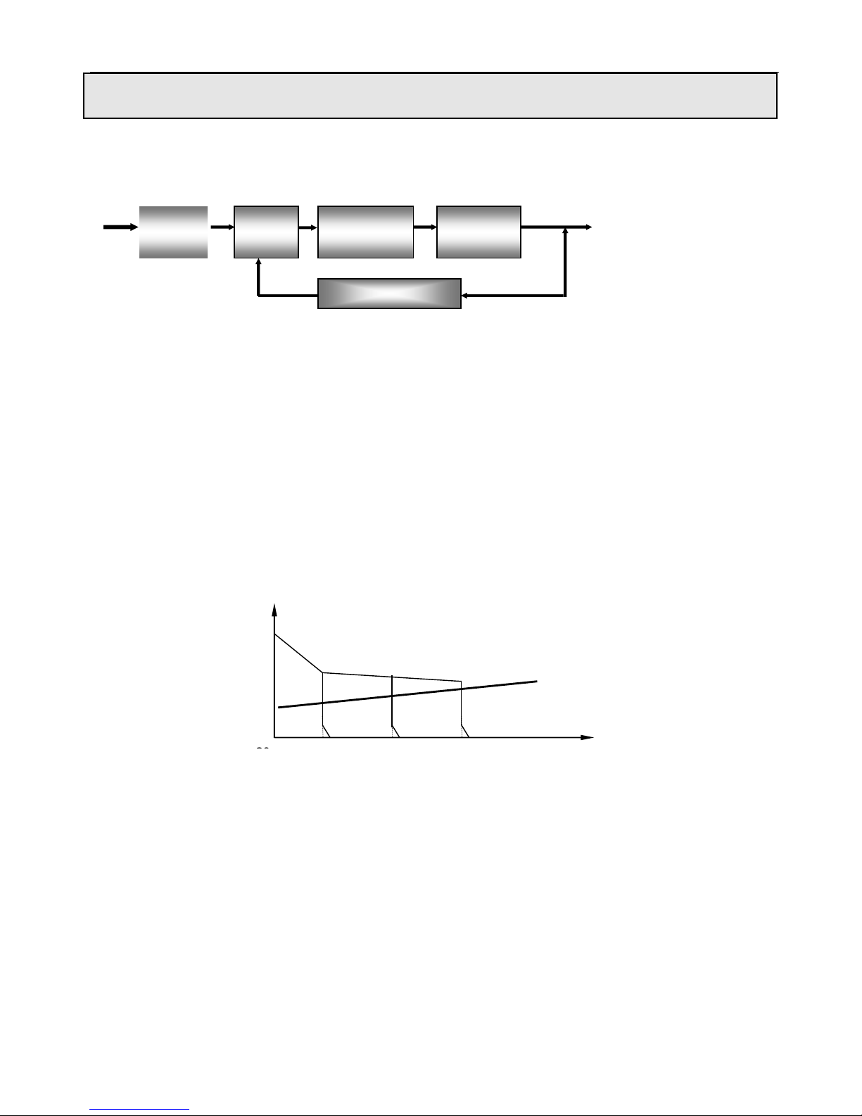
ARC-E series Block diagram of principle
Input 3-phase 380V/50Hz Output
Figure 1: Block diagram of principle
This series welding machines apply IGBT soft switch inverter technology. 3- phase 380V input volt are
rectified by rectifier, inverted into HF AC, reduced by HF transformer, rectified and filtered by HF rectifier,
then output DC power suitable for welding. After this process, the welder’s dynamical responsive speed has
been greatly increased, so the welder size and weight are reduced noticeably result in energy saving. Power
source enjoy sound anti-fluctuating ability and high-quality performance during external context changes
(As to fluctuation in input power supply and extended welding cables). Easy to arc start, stable arc length,
pretty weld formation and capability of continuous regulation of welding current and arc force current.
Inverter DC arc welding machines output characteristic curve is as follows:
Figure 2: Volt-Ampere curve
3 phase
Rectifier
HF
Inverter
HF
Transformer
Rectifier &
Filter
Control circuit
90–
U(V)
U=20+0.04I
I(A)
Page 4

ARC-E 400
3
1. Main technical parameters
Description
Parameters
ARC315E
ARC400E
ARC500E
Rated input voltage
3 phase 380V±10%/50Hz
Rated output capacity
10.3KW
14.4KW
20KW
Rated input current
21A
28A
38A
Rated duty cycle
60%
Range of output current
20~315A
20~400A
20~500A
Rated open load voltage
70V
70V
82V
Full-load efficiency
89%
Power factor(full-load)
0.95
Welding electrode diameter
2~5mm
2~6mm
2~6mm
Weight
29Kg
29Kg
30Kg
Dimension
501×232×495 mm
Insulation grade
H/B
Table1: Parameter Specification
Page 5
ARC-E 400
4
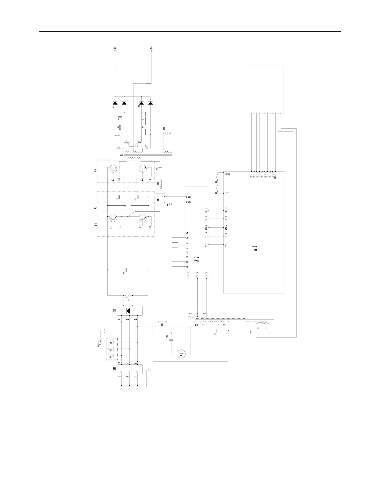
2. Main circuit diagram
Figure 3: Main Circuit Diagram
Page 6

ARC-E 400
5
3. Components List
ARC315E /400E
No.
Tab
Item
Stock No.
Quantity
1
QB1
Circuit breaker
745011-00049
1
2
C1~C3
Polypropylene capacitor
722001-00023
3
3
Q1、Q2
IGBT module
735007-00046
2
4
TB1
3-phase rectifier module (small)
735005-00009
1 5 RE1
Varistor
720021-00017
1 6 C4
Polypropylene capacitor
722001-00070
1 7 A3
IGBT protection board
220005-00056
1
8
BE1
Power Inductor
220149-00070
1 9 RA1
Resonance Inductor
220521-00037
1
10
C7
Polypropylene capacitor
722001-00073
1
11
T1
Main transformer
220629-00090
1
12
RA2
Current exchange inductor
220281-00021
1
13
RB1、RB2
Fast recovery diode module
735006-00027
2
14
GQ1
Fan
746001-00011
1
15
FA1
Fuse
745007-00012
1
16
T2
Transformer for ZKB/QDB
763001-00136
1
17
A1
Main control board
210580-00362
1
18
A2
Drive board
210310-00069
1
19
BB1
Thermal
745008-00006
1
20
BB2
Thermal
745008-00008
1
21 Digital displayer
755001-00003
1
22
Potentiometer
720031-00030
1
23
Potentiometer
720031-00042
2
Table 2: Components List for ARC315E/400E
Page 7

ARC-E 400
6
ARC500E
No.
Tab
Item
Stock No.
Quantity
1
QB1
Circuit breaker
745011-00050
1 2 C1~C3
Polypropylene capacitor
722001-00023
3
3
Q1、Q2
IGBT module
735007-00068
2
4
TB1
3-phase rectifier module (small)
735005-00010
1 5 RE1
Varistor
720021-00017
1 6 C4
Polypropylene capacitor
722001-00070
1 7 A3
IGBT protection board
220005-00057
1 8 BE1
Power Inductor
220149-00071
1
9
RA1
Resonance Inductor
220521-00037
1
10
C8
Polypropylene capacitor
722001-00073
1
11
T1
Main transformer
220629-00103
1
12
RA2
Current exchange inductor
220281-00021
1
13
RB1、RB2
Fast recovery diode module
735006-00029
2
14
GQ1
Fan (1-phase 380V)
746001-00017
1
15
FA1
Fuse
745007-00012
1
16
T2
Transformer for ZKB/QDB
763001-00113
1
17
A1
Main control board
210580-00370
1
18
A2
Drive board
210310-00069
1
19
BB1
Thermal
745008-00006
1
20
BB2
Thermal
745008-00008
1
21
Digital displayer
755001-00003
1
22
Potentiometer
720031-00042
2
23
Potentiometer
720031-00030
1
Table 3: Components List for ARC500E
Page 8

ARC-E 400
7
Features & Applications
ARC-E series inverter arc welding machines are manufactured in line with the following standards:
GB15579, 1-2004 “ARC Welding Equipments· Part One· Power Source”.
This series machines are SMAW machines with different specifications of rated current: 315A, 400A,
500A, which are novelty high-efficient and energy-saving DC Arc welders, not only are used in carbon
steel and low alloy steel welding, but also used in stainless steel, high alloy steel, copper, silver,
molybdenum and titanium welding.
Features and Benefits:
● High duty cycle. Small size, light weight.
● Welding current can be adjustable in very wide range.
● Low welding spatter.
● Easy to arc-starting and molten pool control
● Digital display for accurate parameter preset.
● Soft switch technology, high efficiency.
Applications:
● Shipbuilding and offshore engineering
● Maintenance and repair
● Industry plant construction
● Pipeline industry
Page 9

ARC-E 400
8
Installation Guide
1. Pre-installation
1.1 Installation Environment
The ARC-E series is designed for use in adverse environments. Examples of environments
with increased adverse conditions are:
In locations in which freedom of movement is restricted, so that the operator is forced to
perform the work in a cramped (kneeling, sitting or lying) position with physical contact with
conductive parts;
In locations which are fully or partially limited by conductive elements, and in which there is
a high risk of unavoidable or accidental contact by the operator;
In wet or damp hot locations where humidity or perspiration considerably reduces the skin
resistance of the human body and the insulation properties of accessories.
Environments with adverse conditions do not include places where electrically conductive
parts, in the near vicinity of the operator, which can cause increased hazard, have been
insulated.
The gradient of ground must be no more than 10°
Ensure no wind at the welding position, or use screen to block the wind.
When using water-cooled torch, must be care of not being frozen.
Welding power sources with degree of protection IP21S may be stored, but are not intended to
be used outside during precipitation unless sheltered.
1.2. Installation Location
Be sure to locate the welder according to the following guidelines:
In areas, free from moisture and dust.
Ambient temperature between 0 degrees C to 40 degrees C.
In areas, free from oil, steam and corrosive gases.
In areas, not subjected to abnormal vibration or shock.
In areas, not exposed to direct sunlight or rain.
Place at a distance of 12" (304.79mm) or more from walls or similar boundaries that could
restrict natural airflow for cooling.
Page 10

ARC-E 400
9
1.3 Power Source Connections
Warning
Thermal Arc advises that this equipment be electrically connected by a qualified electrician.
ELECTRIC SHOCK can kill; SIGNIFICANT DC VOLTAGE is present after removal of
input power.
DO NOT TOUCH live electrical parts.
SHUT DOWN welding power source, disconnect input power employing lockout/tagging
procedures.
Lockout/tagging procedures consist of padlocking line disconnect switch in open position.
Removing fuses from fuse box, or shutting off and red-tagging circuit breaker or other
disconnecting device.
1.4.Power Supply Requirements
Input volt must be standard sine wave, effective value 380V, 50Hz.
Unbalance degree of 3- phase volt must be no more than 5%.
Power supply:
Product model
ARC315E
ARC400E
ARC500E
Power supply
3 phase AC 380V
Min. power capacity
21KVA
28KVA
38KVA
Input protection
Fuse
40A
50A
63A
Breaker
63A
63A
100A
Min. Cable size
Input side
2.5mm2
2.5mm2
4mm2
Output side
35mm2
50mm2
70mm2
Earth lead
2.5mm2
2.5mm2
4mm2
Table 4: Power supply connection
Note: The size of fuse and breaker in the table are for reference only.
Page 11
ARC-E 400
10
2. Installation
The machines are portably designed, can be effortlessly moved by operators without fix-up. But it
should be settled in even and dry places with well ventilation.
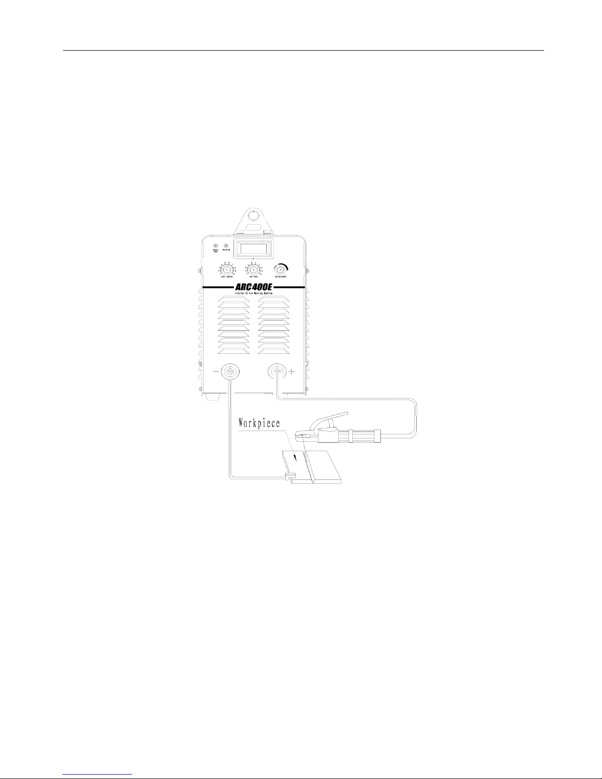
(1) Ensure the welding cable be connected to the power source firmly.
(2) Adjust every knobs, and switches on the front panel to proper position in line with selected mode.
(3) Turn on the circuit breaker on the power source.
(4) Connect input 3 phase primary power cable to switch box.
Figure 4: Outside connection diagram of ARC-E series
Attention: Before you plug the welding cable, please turn off the power and rightly calibrate the plug key
to the socket slot at first, then insert and turn the plug clockwise until it firmly seated. Make sure the
plug and the socket are well-connected to be sound conductivity in case that they are burnt out by over
resistance heat.
Page 12
ARC-E 400
11
Operating Instruction
1. Functional introduction
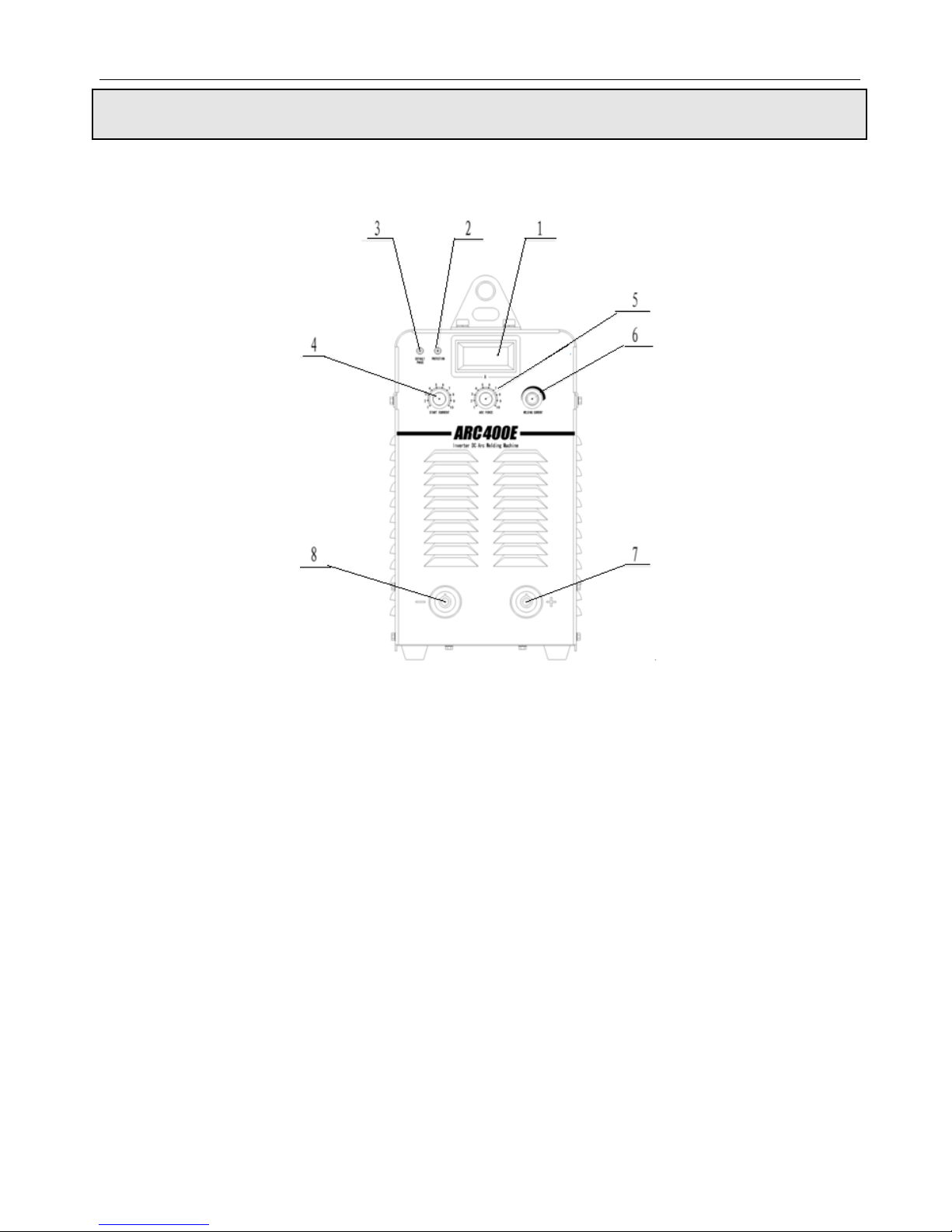
1.1 Front panel illustration and parts number reference
Figure 5: Front Panel
(1) Amp LCD
(2) Protection on LED
Welding machine will automatically stop working when it is overheat, and the LED will be light
up.
(3) Default Phase on LED
It indicates whether the input voltage is phase missing, if default phase, the LED will be light
up.
(4) Arc-starting current regulation knob
Used to adjust the arc-starting current
(5) Arc force current regulation knob
Used to adjust arc force current
Page 13
ARC-E 400
12
(6) Welding current regulation knob
Used to adjust welding current on panel
(7) Welding cable (+) quick socket
Connect to electrode holder.
(8) Welding cable (-) quick socket
Connect to workpiece.
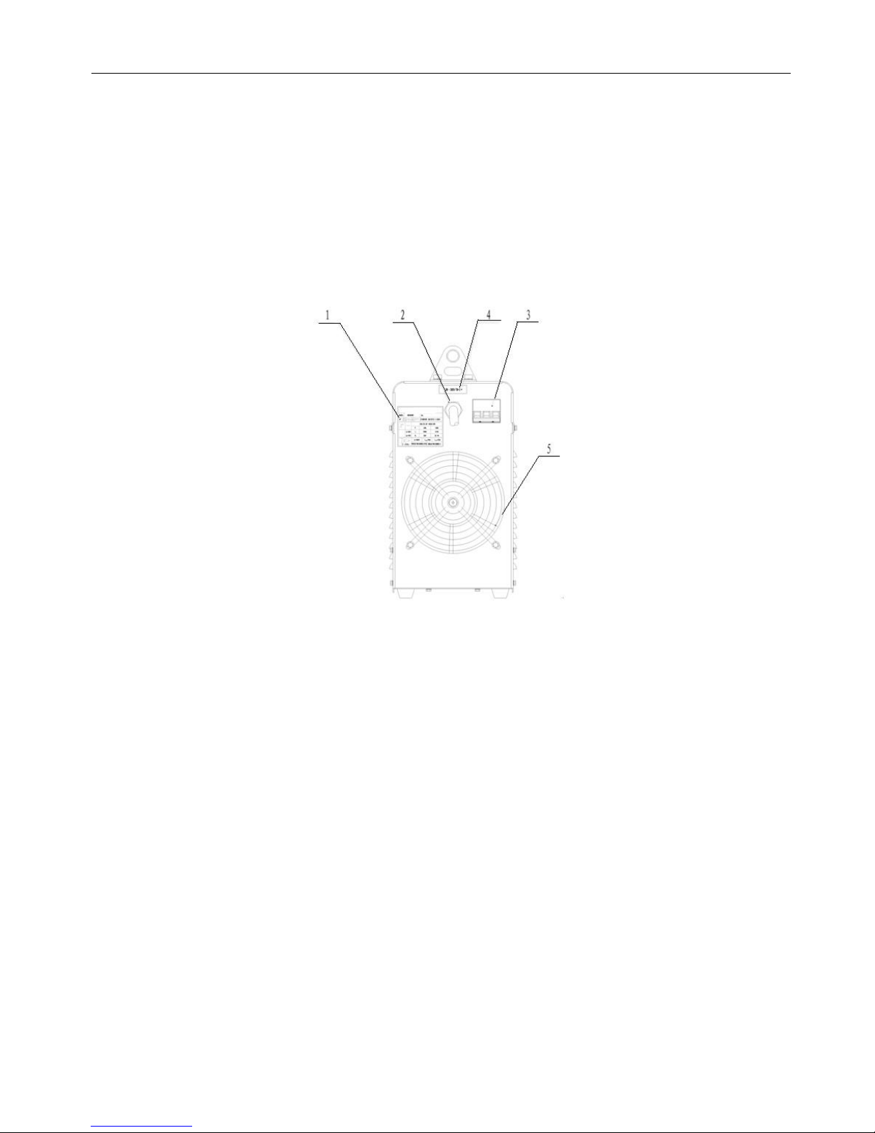
1.2 The rear panel and parts number reference
Figure 6: Rear panel
(1) Specification plate
(2) Input power cable
It is 4-pin cable. The mixed-colored wire must be firmly grounded, the rest wires connect to
corresponding 3-phase power supply.
(3) Circuit breaker
The function of circuit breaker is to protect welding machine by automatic trip to turn-off power
supply while in machine overload or failure. Normally, the switch flipped to upward means
power-on. Use switch on the switch box to start or stop welding machine. Don’t use this air switch
as power switch.
(4) Input warning mark
(5) Cooling fan
Page 14

ARC-E 400
13
2. Operating instruction
Turn on the air switch on the switch box, the “Normal” indication lamp will light on and cooling fan rotates. Before
welding normally, set up parameters by adjusting knobs and switches on the front panel according to the selected mode.
Customer should refer to parameters defined in table 5 showing below:
Work piece thickness(mm)
<1
2
3
4~5
6~12
≥13
Electrode diameter(mm)
1.5 2 3.2
3.2~4
4~5
5~6
Welding current(A)
20~40
40~50
90~110
90~130
160~250
250~400
Table 5: SMAW welding parameters
Page 15

ARC-E 400
14
Repair & Maintenance
WARNING: Have a qualified electrician do the maintenance and trouble shooting work. Turn the input
power off, using the disconnect switch at the fuse box before working inside the machine.
1. Cautions
Rivet equipment name tag on the specified area of the case, otherwise the inside parts will possibly
be damaged.
Connect welding cable to terminals firmly, otherwise the terminals will be burn out which will
cause the instability of welding process.
Avoid welding cable and control cable being broken, and prevent welding machine from being short
circuit.
Never let welding machine be bumped into or stacked up by heavy objects.
Ensure good ventilation
Under high temperature, if work with large current for long period, welder may shut down
automatically due to thermal protection acts. At this point, let the machine runs under open-load for
a few minutes, and it will be automatically recover.
Under high temperature, if work with large current for long period, welder may shut down
automatically due to air switcher trips. Cut off the power supply to the electricity switchboard on
frame, and wait for 5 minutes to turn on the circuit breaker on the power source fist then connect
the power supply to the electricity switchboard on frame. And leave the machine runs under
open-load condition for a while.
After welding, cut off power supply.
2. General maintenance
Remove dust from power resource with pressure air by qualified individuals every 3-6 months.
Check if the jointers are loose.
Check regularly if cables are worn out, knobs are loose, and components of panel are damaged.
Check regularly if cables are tightly connected to cable connecting terminals in case of terminals
being burnt out.
3. Procedure for regular checking prior to maintenance
Check if all front panel switches are on the proper positions.
Page 16

ARC-E 400
15
Check if the input volt has the phase missing, and range are between 340~420V.
Check if the input cable is connected correctly and firmly with the power source.
Check if the welding cables are connected correctly and firmly.
WARNING: Have a qualified electrician do the maintenance and trouble shooting work. Turn the input
power off, using the disconnect switch at the fuse box before working inside the machine. Don’t open up
case uninstructed, the max volt inside machine is 600V, Never discharge high voltage to welder case with
welding torch! Shut down power source before changing or repairing welding cable or torch
№
TROUBLE
CAUSES
WHAT TO DO
1
After power on,
the machine does
not work.
(1) Phase missing in power source
(2) Fuse(2A)in welder is broken.
(3) Cable is broken
(1) Check power source
(2) Check if cooling fan,
transformer for ZKB/QDB
and main control board are
good or not.
(3) Check connection
2
Circuit breaker on
back panel trips
while the machine
is working
normally.
(1) The following components
may be damaged: IGBT module,
3-phase rectify module, outputting
diode module, or other components
(2) Drive board is damaged.
(3) Short circuit between lines.
(1) Check and replace.
(2) When IGBT module is
damaged.
3
Welding current is
unstable.
(1) Phase missing
(2) The following components
may be damaged: Potentiometers,
switches on front panel.
(3) Main control board is damaged
(1) Check power source.
(2) Check and replace.
4
Welding current is
not adjustable.
(1) Potentiometer of welding
current adjustment is damaged.
(2) Main control board is
damaged.
Check and replace.
Table 6: Trouble Shooting Table
Page 17

ARC-E 400
16
Appendix A
1. General
The user is responsible for installing and using the arc welding equipment according to the
manufacturer’s instructions. If electromagnetic disturbances are detected, then it shall be the
responsibility of the user of the arc welding equipment to resolve the situation with the technical
assistance of the manufacturer. In some cases this remedial action may be as simple as earthling the
welding circuit, see note. In other cases it could involve constructing an electromagnetic screen
enclosing the welding power source and the word complete with associated input filters. In all cases
electromagnetic disturbances shall be reduced to the point, where they are no longer troublesome.
NOTE: The welding circuit may not be earthed for safety reasons. Changing the earthling
arrangements should only be authorized by a person who is competent to assess whether the
changes will increase the risk of injury.
2. Assessment of area
Before installing arc welding equipment the user shall make an assessment of potential electromagnetic
problems in the surrounding area. The following shall be taken into account:
1) Other supply cables, control cables, signaling and telephone cables, above, below and adjacent to the
arc welding equipment;
2) Radio and television transmitters and receivers;
3) Computer and other control equipment;
4) Safety critical equipment, for example guarding of industrial equipment;
5) The health of the people around, for example the use of pacemakers and hearing aids;
6) Equipment used for calibration or measurement;
7) The immunity of other equipment in the environment is compatible. The user shall ensure that other
equipment being used in the environment is compatible. This may require additional protection
measures;
8) The time of day that welding or other activities are to be carried out.
Page 18

ARC-E 400
17
3. Methods of reducing emissions
1) Public supply system
Arc welding equipment should be connected to the public supply system according to the
manufacturer’s recommendations. If interference occurs, it may be necessary to take additional
precautions such as filtering of the public supply system. Consideration should be given to shielding
the supply cable of permanently installed arc welding equipment, in metallic conduit or equivalent.
Shielding should be electrically continuous its length. The shielding should be connected to the
welding power source so that good electrical contact is maintained between the conduit and the
welding power source enclosure.
2) Maintenance of the arc welding equipment
The arc welding equipment should be routinely maintained according to the manufacturer’s
recommendations. All access and service doors and covers should be closed and properly fastened
when the arc welding equipment is in operation. The arc welding equipment should not be modified in
any way, except for those changes and adjustments covered in the manufacturer’s instructions. In
particular, the spark gaps of arc striking and stabilizing devices should be adjusted and maintained
according to the manufacturer’s recommendations.
3) Welding cables
The welding cables should be kept as short as possible and should be positioned close together,
running at or close to the floor level.
4) Equipotent bonding
Bonding of all metallic components in the welding installation and adjacent to it should be considered.
However, metallic components bonded to the word piece will increase the risk that the operator could
receive an electric shock by touching these metallic components and the electrode at the same time.
The operator should be insulated from all such bonded metallic components.
5) Earthling of the work piece
Where the work piece is nor bonded to earth for electrical safety, nor connected to earth because of its
size and position, for example ships hull or building steelwork, a connection bonding the work piece
to earth may reduce emissions in some, but not all instances. Care should be taken to prevent the
earthling of the work piece increasing the risk of injury to users, or damage to other electrical
equipment. Where necessary, the connection of the work piece to earth should be made by a direct
connection to the work piece, but in some countries where direct connection is not permitted, the
Page 19

ARC-E 400
18
bonding should be achieved by suitable capacitance, selected according to national regulations.
6) Screening and shielding
Selective screening and shielding of other cables and equipment in the surrounding area may alleviate
problems of interference. Screening of the entire welding installation may be considered for special
applications.
Page 20

ARC-E 400
19
Appendix B
Feedback Form
Name of Company
Address
Contact person
Title
Telephone No
Fax No.
Email Address
Company’s filed of business
Comments:
Thank you for taking the time to share your feedback. Your comments and suggestions will help us to serve
you better.
 Loading...