

Weir ROTO-JET R0, ROTO-JET R11, ROTO-JET RD11, ROTO-JET 2100, ROTO-JET 2200 Installation, Operation & Maintenance Manual
...Page 1
Excellent
Engineering
Solutions
Installation, Operation &
Maintenance Manual
Model RO, RG, R11,
RD11, 2100, 2200
RJ-IOM 03/15
Page 2

ROTO-JET PUMP
INSTALLATION, OPERATION & MAINTENANCE MANUAL
Models RO, RG, R11, RD11, 2100, 2200
Table of Contents
I. GENERAL ................................................................................................. 1
A. INTRODUCTION ............................................................................. 1
B. PUMP IDENTIFICATION ................................................................ 2
C. RECEIVING INSPECTION ............................................................. 2
D. UNLOADING ............................................................................................................ 2
E. STORAGE INSTRUCTIONS ................................................................................ 3
II. INSTALLATION ......................................................................................... 4
A. LOCATION OF PUMP .................................................................... 4
B. INSTALLATION ON FOUNDATION ............................................... 4
C. GROUTING ..................................................................................... 5
D. PIPING ............................................................................................ 6
1. GENERAL ............................................................................ 6
2. BYPASS ............................................................................... 6
3. FILTRATION ........................................................................ 9
4. SEAL DRAIN ........................................................................ 9
5. SEAL FLUSH ..................................................................... 10
E. ALIGNMENT ................................................................................. 10
F. V-BELT DRIVE.............................................................................. 12
G. ELECTRIC MOTOR DRIVE .......................................................... 13
H. GUARDS ....................................................................................... 13
i
Page 3

ROTO-JET PUMP
INSTALLATION, OPERATION & MAINTENANCE MANUAL
Models RO, RG, R11, RD11, 2100, 2200
Table of Contents
(continued)
III. OPERATION ............................................................................................ 14
A. OPERATION LIMITS AND DATA ................................................. 14
B. BEFORE STARTING .................................................................... 15
C. START-UP .................................................................................... 16
D. OPERATING CHECKS ................................................................. 17
E. OPERATING CAUTIONS ............................................................. 17
F. SHUTDOWN ................................................................................. 18
IV. MAINTENANCE ....................................................................................... 19
A. GENERAL ..................................................................................... 19
B. MAINTENANCE TIMETABLE ....................................................... 20
C. V-BELT DRIVE.............................................................................. 20
D. STRAINER .................................................................................... 21
E. MECHANICAL SEAL .................................................................... 21
F. BEARING LUBRICATION ............................................................. 21
1. OIL LUBRICATED .............................................................. 21
2, GREASE LUBRICATED (RG, 2100) .................................. 22
G. BEARING SYSTEM ...................................................................... 23
H. ROTOR AND ROTOR COVER ..................................................... 23
I. PICK-UP TUBE ............................................................................. 23
J. OPERATING MAINTENANCE RECORDS ................................... 24
ii
Page 4

ROTO-JET PUMP
INSTALLATION, OPERATION & MAINTENANCE MANUAL
Models RO, RG, R11, RD11, 2100, 2200
Table of Contents
(continued)
V. TROUBLESHOOTING ............................................................................. 25
A. NO LIQUID DELIVERED .............................................................. 25
B. NOT ENOUGH LIQUID DELIVERED ............................................ 26
C. NOT ENOUGH PRESSURE ......................................................... 27
D. PUMP OVERLOADS DRIVER ...................................................... 28
E. PUMP WORKS FOR AWHILE THEN QUITS ............................... 28
F. PUMP VIBRATION ....................................................................... 29
G. BEARINGS OVERHEAT OR WEAR RAPIDLY ............................ 29
H. LIQUID RUNS FROM DRAIN HOLE ............................................. 30
I. NOISE. .......................................................................................... 30
VI. PARTS ..................................................................................................... 31
A. SPARE PARTS LISTS .................................................................. 31
B. ORDERING PARTS ...................................................................... 31
C. ASSISTANCE ............................................................................... 31
iii
Page 5
ROTO-JET PUMP
MODELS RO, RG, R11, RD11, 2100 AND 2200
INSTALLATION, OPERATION AND MAINTENANCE MANUAL
WARNING
PLEASE STUDY THESE INSTRUCTIONS CAREFULLY BEFORE PUTTING THE
PUMP INTO SERVICE. ADHERENCE TO THESE INSTRUCTIONS IS NECESSARY
FOR SATISFACTORY START-UP OF YOUR ROTO-JET PUMP. OPERATING
PERSONNEL MUST READ AND UNDERSTAND THE START-UP AND OPERATION
PARAGRAPHS.
I. GENERAL
A. INTRODUCTION
This manual has been prepared to assist you in understanding the construction and
the correct methods of installing, operating and maintaining your new Roto-Jet
Pump.
The design, material, and workmanship incorporated in the construction of the RotoJet Pump makes it capable of giving long, trouble-free service. The life and
satisfactory service of any mechanical unit, however, is dependent upon correct
application, proper installation, periodic inspection and careful maintenance. For
this reason, you are urged to read and follow the directions in this manual.
The exclusive patented Roto-Jet Pump has only two basic working parts…a rotating
case and a stationary pick-up tube collector arm within the rotating case. The RotoJet design completely eliminates the need for packing glands, wear rings or multiple
stages as used in conventional centrifugal pumps, and also eliminates the complex
pistons, rods, valves and springs required in reciprocating pumps.
The Roto-Jet Pump operates in the following manner: liquid enters the intake
manifold and passes into the rotating case where centrifugal force increases the
velocity and pressure of the liquid. The velocity of the liquid in the rotor is converted
into additional pressure as it jets into the pick-up tube.
1
Page 6
B. PUMP IDENTIFICATION
Roto-Jet Pumps are described by a series of letters and numbers, such as RGBS484 or 2100. The first group is the model and indicates the basic mechanical
configuration, and the second group, S484, indicates the pick-up tube size.
Each pump nameplate will show the pump, model, size, and serial number.
When ordering parts, or inquiring about service, this information must be supplied.
This will insure that the proper size and material of parts are supplied.
C. RECEIVING INSPECTION
Prior to signing any shipping documents, inspect the shipment for shortages or
damages and promptly report any to the carrier, noting damage on the freight bill,
receipt, and bill of lading. MAKE ANY CLAIMS TO THE TRANSPORTATION
COMPANY PROMPTLY.
Do not remove any tags or shaft protector. Instruction sheets on various
components as well as the Operation and Maintenance Manual for the pump are
included in the shipment. DO NOT DISCARD!
D. UNLOADING
Care must be taken when unloading pumps.
WARNING
EQUIPMENT LIFTING DEVICES SUCH AS CHAIN, LIFTING EYES, HOOKS, ETC.
MUST BE APPROVED BY LOCAL, STATE OR FEDERAL SAFETY CODES.
HOISTS AND CRANES MUST BE ADEQUATELY SIZED TO LIFT RATED LOADS.
FAILURE TO USE APPROVED LIFTING DEVICES MAY RESULT IN INJURY.
WHEN LIFTING THE PUMP, IT IS IMPORTANT TO MAKE SURE THAT THE
CHAIN AND CABLES ARE FASTENED RELIABLY TO THEIR RETAINING
HOOKS.
The unit should be carefully supported when unloaded. Under no circumstances
should it be dropped or receive rough handling. Exercise the same care with this
pump as you would with other pieces of engineered equipment. Lifting devices must
be securely attached to the lifting lugs on the base.
2
Page 7
THE EYEBOLT HOLE LOCATED ON THE TOP OF THE PUMP HOUSING IS
INTENDED FOR LIFTING THE PUMP ONLY, AND NOT THE COMPLETE PUMP
AND BASE PACKAGE.
E. STORAGE INSTRUCTIONS
If the pump is not to be installed and operated immediately, store in a clean, dry
place. ROTO-JET Pump assumes the units will be placed in operation a few weeks
after shipment, so no special protection is given the pump, drive or motor.
Do not remove the shaft protector until the pump has been mounted. Do not
remove the inlet and discharge connection plugs until the unit is to be piped. Store
in an area where temperature is reasonably constant.
Parts subject to attack by moisture, such as bearings, shaft, suction and discharge
threaded openings, and other finished parts should be inspected periodically and
coated with lubricant or rust preventative.
IF THE PUMP IS TO BE STORED OR NOT PLACED IN OPERATION MORE
THAN TWO WEEKS AFTER RECEIPT:
1. Store pump in a clean, dry place free from vibration and extremes in
temperature.
2. Protect all exposed, unpainted surfaces from rust.
3. On RO, ROH, R11 and 2200 pumps every two weeks remove the Pedestal
Cover and spray the bearings with a light coat of oil (MOBIL DELVAC 1 ESP
5W-40 ). No additional lubrication is needed on RG pumps. ROTATE THE
PUMP SHAFT 2 OR 3 REVOLUTIONS BY HAND EVERY TWO WEEKS.
After prolonged storage, the bearing lubrication instructions in this Operation
and Maintenance Manual must be followed.
4. Accessories such as drives, etc. should be protected in accordance with the
accessory manufacturer’s instructions.
Following these recommendations will help ensure that the pumps will operate
without problems and give long, trouble free service.
WARNING
3
Page 8

II. INSTALLATION
A. LOCATION OF PUMP
Leave sufficient room in front of the pump to remove the manifold for seal
replacement.
The pump should be located where there is sufficient accessibility for inspection and
maintenance. A clear space with ample headroom should be allowed for the use of
an overhead crane or hoist sufficiently strong to lift the unit.
Select a dry place above the floor level whenever possible. Take care to prevent
the pump from freezing during cold weather. Refer to Section III, F., “Shutdown”.
The pump must be located relative to the system so as to insure that sufficient
NPSH (Net Positive Suction Head) is provided at the pump inlet. Available NPSH
must always equal or exceed the required NPSH as shown on the pump
performance curves.
Whenever possible, the pump should be located below reservoir fluid level to
facilitate priming.
B. INSTALLATION ON FOUNDATION
A properly mounted base on a rigid foundation is essential for a smooth running
pump. The foundation should minimally be a 4” (100 mm) thick concrete slab floor
or an 8” (200 mm) thick concrete pad, extending two inches larger in width and
length than the pump or unit, and should be steel reinforced according to local
building codes.
The pump and drive assembly should be placed on the foundation with the coupling
halves disconnected. On belt driven units, the belts may remain on the sheaves.
The alignment operation must be completed before the coupling is reassembled**.
(See Section VII.) The baseplate should be supported on metal wedges or metal
blocks as illustrated in figures 1 and 2. The support wedges, or blocks, should be
placed close to the anchor bolts.
4
Page 9
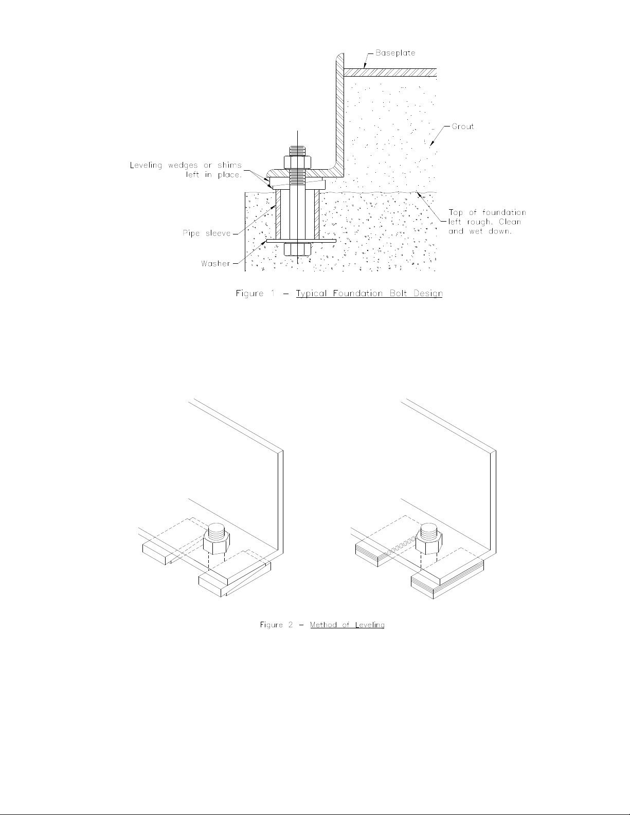
Adjust the metal wedges, or blocks, around base edge until the base is level. Then
suction flanges, discharged flanges and coupling faces should be checked by
means of a level. Corrections may be made for flange or coupling level or plumb by
shims under the pump or motor.
5
Page 10
C. GROUTING
Evenly adjust all anchor bolts, but not too firmly, after first alignment is complete.
The baseplate can be grouted to the foundation. On open type baseplates fill the
internal spaces with non-shrink grout to the top of the baseplate. For closed type
baseplates all the voids under the baseplate must be filled with non-shrink grout.
Grouting holes are provided in the baseplate.
It is desirable to grout all wedges and blocks in place. Anchor bolts should not be
fully tightened until the grout has hardened, approximately 48 hours after pouring.
D. PIPING
1. GENERAL
The pump should be installed as close to the reservoir or fluid supply as
possible, with the inlet piping as short and as direct as practical. The minimum
recommended pipe size is 2” (50 mm) for 2x2 manifolds and 3” (80 mm) for
3x2 manifolds. When open supply tanks are used, 3” (80 mm) pipe or larger
may be required for suction piping. This will depend on flow, fluid temperature,
fluid vapor pressure, and losses in elbows, valves and strainers.
Both inlet and discharge piping must be independently supported near the
pump and properly aligned so that no pipe strain is transmitted to the pump
manifold.
WARNING
SUCH PIPE STRAINS COULD RESULT IN STRUCTURAL FAILURE
LEADING TO INJURY.
The inlet piping should slope upward to the pump. A horizontal suction line
must have a gradual rise to the pump. Any high point in the piping will become
filled with air and thus prevent proper operation of the pump. When reducing
the piping to the inlet opening diameter, use an eccentric reducer with the
eccentric side down (flat side up). Never use a straight taper (concentric)
reducer in a horizontal suction line, as it tends to form an air pocket in the top
of the reducer and the pipe.
WARNING
THE PUMP AND PIPING SYSTEM MUST BE PROTECTED FROM THE
EFFECTS OF WATER HAMMER (PRESSURE SURGE) WHEN USING A
QUICK-CLOSING VALVE OR ANY DEVICE CAPABLE OF RAPIDLY
SHUTTING OFF SYSTEM FLOW.
6
Page 11
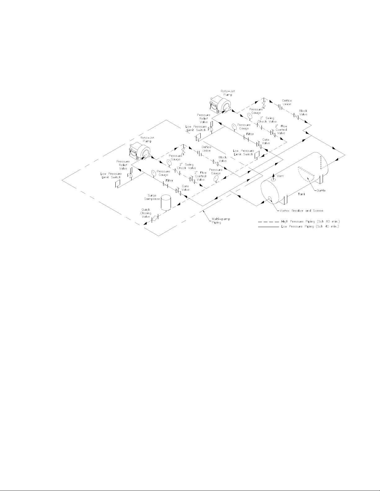
PIPING DIAGRAM
Properly sized pressure gauges should be installed in both the inlet and
discharge lines. The gauges will allow the operator to easily observe the inlet
and discharge pressures of the pump and thereby determine if the pump is
operating according to the performance curve. If cavitation, vapor binding or
other unstable operation should occur, a widely fluctuating discharge pressure
will be noted.
If there is any possibility of high pressure remaining on the outlet of the pump
after the pump has been shut down (as with two or more pumps operating in
parallel or when pumping to a high pressure reservoir), a check valve must be
added to the discharge side of the pump and a pressure relief valve, set at 225
psi (15.5 bar) or less, must be installed in the inlet piping between the pump
and the intake shut-off valve. This will prevent damage to the mechanical seal
and the inlet piping.
7
Page 12
2. BYPASS
Like other centrifugal type pumps, the Roto-Jet Pump loses a certain amount of
power in churning the fluid within the pump. This lost power is converted to
heat. If the pump is operated at or near shut-off (no flow), the temperature of
the fluid within the pump will rise to unacceptable levels, and could cause seal
failure or various other problems.
It is therefore necessary to have a fluid bypass to remove this heat and insure
adequate seal lubrication.
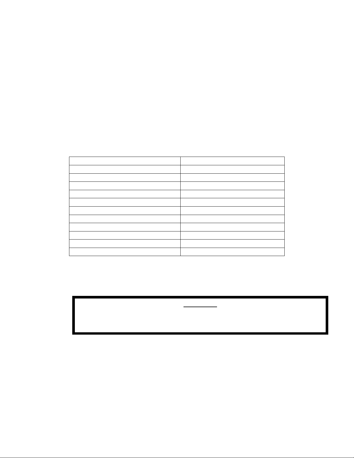
The minimum recommended bypass flow should be approximately 10% of the
peak efficiency flow of the pump. Listed below are applicable bypass orifice
sizes which will meet the bypass flow requirement of the Roto-Jet Pump
selected:
MODEL ORIFICE SIZE
R11, RD11-S252 3/32” (2.387 mm)
R11, RD11-S338 3/32” (2.387 mm)
R11, RD11-S433 1/8” (3.175 mm)
R11, RD11-D433 5/32” (3.962 mm)
RG, RO, 2100, 2200-S266 3/32” (2.387 mm)
RG, RO, 2100, 2200-S375 3/32” (2.387 mm)
RG, RO, 2100, 2200-S484 1/8” (3.175 mm)
RG, RO, 2100, 2200-D484 1/8” (3.175 mm)
RG, RO, 2100, 2200-S600 1/8” (3.175 mm)
RG, RO, 2100, 2200-D600 5/32” (3.962 mm)
RO-D850 5/16” (7.930 mm)
We recommend that ½” (13 mm) bypass line be installed (tee-in) in the
discharge line of the pump, between the pump and the discharge valve. The
bypass line should be piped back to the suction reservoir, or to a drain.
WARNING
NEVER PIPE THE BYPASS LINE DIRECTLY INTO THE INTAKE OR
SUCTION LINE OF THE PUMP.
Roto-Jet optionally furnishes a valve and gauge package which includes an
outlet throttle valve, a pressure gauge, a tee, and bypass orifice, ready to
connect to the pump discharge line and a bypass line.
8
Page 13
WARNING
A VORTEX BREAKER, SCREEN, AND/OR BAFFLE MAY BE REQUIRED IF
THE TANK IS SMALL OR THE BYPASS RETURN LINE IS TOO CLOSE TO
THE PUMP SUCTION LINE.
Block valves are required in the bypass line if the line enters the reservoir
below the fluid surface.
3. FILTRATION
As a minimum recommendation, install a 100 Mesh (149 Micron) strainer or
equivalent filtration device in the suction piping adjacent to the pump to prevent
mill scale, rust and other foreign material from damaging the pump.
WARNING
THE ROTO-JET PUMP IS NOT DESIGNED TO PUMP ABRASIVES AND IS
NOT WARRANTED AGAINST ABRASIVE DAMAGE OR WEAR. IT WILL
NORMALLY OPERATE SATISFACTORILY WITH UP TO 100 PPM
SUSPENDED SOLIDS, BUT WEAR WILL DEPEND ON THE PARTICLE SIZE
AND HARDNESS. CONSULT FACTORY FOR FILTRATION AND SPECIAL
PARTS RECOMMENDATIONS IF THIS LEVEL IS EXCEEDED.
4. SEAL DRAIN
In the event of seal failure, the leakage will exit from the seal drain. Piping may
be connected to the seal drain (except the RG 2x2) and piped away from the
unit, but it should never be plugged. If pumping other than water, please
consult the factory. Leakage should be monitored for identification of seal
failure.
5. SEAL FLUSH
Unless the pump was equipped for seal flush, the seal flush inlet should remain
plugged. If seal flush is necessary, the tubing or piping should be connected to
the seal flush inlet. It is recommended that the flush fluid be supplied at 2-3
gpm (.5-.7 m3/hr) flow rate and 15-20 psig (1-1.4 bar) pressure above the inlet
pressure. Flush fluid temperature is dependent on pump duty and temperature
of pumped fluid. Please consult factory.
9
Page 14
E. ALIGNMENT
The pump and driver, if supplied, were not aligned at the factory since the unit can
shift during shipment. Couplings are disconnected for shipment and belts
untensioned. The pump and driver shafts must be checked for angular and parallel
alignment. (Realignment is also necessary after the grout has hardened and anchor
bolts have been tightened.) The alignment must be finally checked after the piping
has been completed and rechecked periodically. In accurate alignment results in
vibration and excessive wear on bearings, shaft sleeves or mechanical seals.
WHEN CHECKING ALIGNMENT OR PERFORMING ANY WORK ON THE UNITS,
ELECTRICAL SERVICE MUST BE LOCKED OUT WITH AN APPROVED
LOCKOUT AND KEY. FAILURE TO LOCKOUT EQUIPMENT MAY RESULT IN
INJURY.
The model suffix A (i.e., ROA) has been designed to be driven through a flexible
coupling and the model suffix B pump has been designed for belt drives. The
bearing system in each model is designed to optimize bearing life with their
respective type drive. Warranty will not be extended to any problems or damage
due to misapplication.
If necessary, the bearing system can be converted to suit the drive system selected.
See Disassembly/Assembly manual.
Flexible Coupling Drive (Model Suffix A)
Flexible couplings are not intended to permit permanent misalignment. Even slight
misalignment will reduce bearing life and cause other problems. Flexible couplings
do permit some temporary slight change in alignment or end play to allow for
unusual momentary loads or thermal expansion during start-up.
The coupling should be installed and aligned according to the manufacturer’s
recommendations. The dimensions and tolerances listed below apply only to the
couplings furnished by Roto-Jet Pump.
WARNING
Motor to Gear Box Coupling Make: Falk Type: T20, Size: 1070 T
Gear Box Shaft: Refer to gear manufacturer’s information, Motor Shaft: Refer
to NEMA Motor Size.
Gap between coupling faces: Minimum 1/16”, Normal 1/8”, Maximum 3/16”
Concentricity between faces: .004” total indicator reading .002” max. centerline displacement
Face parallelism: .002” max. gap variation at edge of coupling
10
Page 15

For coupling parts list and additional installation and maintenance instruction, refer
to the Falk Steelflex Coupling Service Manual 428-110, 428-010 or 428-012.
Start and run unit until normal operating temperature is reached (approximately 1
hour). Shut unit down and check alignments on components at operating
temperature, realign as required.
For Belt-Drive Units (Model Suffix B)
Shaft alignment can be checked by measuring the distance between the shafts at
three or more locations. If the distances are equal, then the shafts will be parallel.
To check the alignment of the sheaves on the shafts, a straightedge or a piece of
string can be used. If the sheaves are properly lined up, the straightedge or string
will touch each sheave at two points and both sheaves at four points simultaneously.
Rotating each sheave a half revolution will determine whether the sheave is wobbly,
or the drive shaft is bent. Correct any misalignment.
The sheaves should be mounted as close as possible to the pump and motor
bearings. With sheaves aligned, tighten cap screws evenly and progressively.
Apply the recommended torque to cap screws as listed below.
Before reinstalling the guards, check the sheaves to be sure there is no grease, oil,
dirt, or rust in the grooves. Any that is present must be removed before starting, or
the belts could be damaged. When replacing belts, a matched set should be
purchased and all belts replaced at the same time. See drive manufacturer
instructions for proper belt tension and other information.
F. V-BELT DRIVE
V-Belt Drive systems should be properly installed to ensure maximum belt life and to
minimize excessive loads or wear on bearings.
Inspect all drive components for damage. Sheaves should be free of oil, grease rust
and burrs.
Gear Box to Pump Coupling Make: Thomas Type: DBZ-C, size: 226
Pump Shaft: 2-1/4”, Gear Box Shaft: Refer to gear manufacturer’s information.
Gap between coupling hub faces to be set at 5” + 1/64”
Concentricity between hub flange O.D. .005: total indicator reading
Face parallelism - .005” maximum gap variation at edge of hub flange.
11
Page 16
Sheaves must be aligned so that when a straight edge is held across the face of the
driven and driver sheaves there is less than .025” gap between the straight edge
and the face of the sheaves. Shafts should be parallel.
Always use a matched set of new belts purchased from manufacturer.
Use only the same section of belt (Example: 3VX) that the sheave was designed
for.
Slack off sheaves until belts can be placed in grooves by hand – without forcing.
Never use a screwdriver, crowbar or other implement. Do not install on the same
sheave some belts with slack side on tope and others with slack side below. Have
slack in all belts on the same side.
Adjust take-up until belts are snug and then tension the drive properly. The
following tensioning information are general guidelines for equipment supplied by
the factory. For specific tensioning data, consult the factory or belt manufacturer.
Measure the span (distance between centerlines of sheaves). The deflection at
mid-span should be 1/64” per in of span. (i.e., for a span of 24”, the deflection is
3/8”). Using a V-belt tension tester, the mid-span face per belt after break-in should
be:
Motor HP/Belt Force (lb)
3 – 5 2 – 3
6 – 8 3 – 4
9 – 10 3-1/2 – 5
25 8 - 12
Check belt tension and alignment several times during the first few days of operation
with new belts.
Never use a belt dressing.
WARNING
ALL GUARD AND PROTECTIVE DEVICES MUST BE INSTALLED BEFORE THE
PUMP IS STARTED. CONTACT WITH UNGUARDED BELTS, SHEAVES, OR
COUPLINGS COULD RESULT IN INJURY.
12
Page 17
G. ELECTRIC MOTOR DRIVE
If the pump driver is an electric motor, a motor starter with overload protection must
be provided. The overload resets should be set according to local code. Refer to
motor nameplate. Direction of rotation of pump shaft must be counterclockwise
when facing pump shaft extension. Make motor electrical connections accordingly.
Changing any two leads on a three phase motor will change direction of motor
rotation.
Be sure that the power source is correct for the driver.
Determine the power to be used, and provide the appropriate wire size.
When a 10HP (7.5 kw) with R11 pumps or 50HP (37.5 kw) with RG, RO, 2100 or
2200 pumps or smaller motor is used, a slow-trip overload relay is
recommended to prevent tripping during start-up. The rotor assembly of a
Roto-Jet pump has a relatively high moment of inertia, and requires an
extended acceleration period with these motors before operating speed is
reached.
H. GUARDS
WARNING
ALL ELECTRICAL CONNECTIONS AND WIRING ARE TO BE IN COMPLIANCE
WITH LOCAL BUILDING AND SAFETY CODES.
DO NOT OPERATE EQUIPMENT WITH OPEN ELECTRICAL BOXES OR
FITTINGS. CONTACT WITH INCORRECTLY WIRED EQUIPMENT COULD
RESULT IN INJURY.
Rotating sheaves and drive belts, must be guarded as required by applicable local
safety codes and OSHA regulations to protect personnel from injury. The pump
should never be allowed to operate until this protection has been provided. A guard
is part of the belt drive package which is optionally furnished by Roto-Jet Pumps.
13
Page 18

(See p
age 16 for footnotes)
OPERATION
PARAMETER
Pump Speed
-Direct Connect
-Belt Drive
Suction Pressure 200 PSIG
MAXIMUM MINIMUM MAXIMUM MINIMUM MAXIMUM MINIMUM MAXIMUM MINIMUM MAXIMUM MINIMUM
RG PUMP RO PUMP
4380 RPM
(13.8 bar)
---
NPSHR
from Curve
4380 RPM
250 PSIG
(17.2 bar)
---
NPSHR
from Curve
RO HIGH SPEED
OPTION
6321 RPM
4380 RPM
(12)
250 PSIG
(17.2 bar)
---
NPSHR
From Curve
4709 RPM
4380 RPM
(12)
200 PSIG
(13.8 bar)
2100 2200
---
NPSHR
From Curve
5443 RPM
4380 RPM
(13)
50 PSIG (3.4
bar) @ 5443
RPM
150 PSIG (10.3
bar) @
5060 RPM
200 PSIG (13.8
bar) @
4709 RPM
---
NPSHR
From Curve
III. OPERATION
A. Operation Limits and Data (RG, RO, ROH, 2100, 2200)
Differential
Pressure (16)
Flow (16) 450 GPM
Specific Gravity (2) 1.2 0.6 1.2 0.6 1.2 0.6 1.2 0.6 1.2 0.6
Horsepower
-Direct Connect
-Belt Drive
Fluid Temperature
-Water Single Seal
-Single Seal with
cooled flush
-Double Seal with
cooled flush
-Other Fluids:
First Critical Speed 6500 RPM ---- 8500 RPM ---- 8500 RPM ---- 7750 RPM ---- 7750 RPM ----
1125 PSIG
(77.6 bar)
(102.2 M3/hr)
400 HP (290 kw)
250 HP (186 kw)
(3)
180° F
(82° C)
250° F
(110° C)
(3x2 only)
250° F
(121° C)
250° F
(121° C)
50 PSIG
(3.4 bar)
2 GPM
(.5 M3/hr)
(4)
Higher of
20° F (-7°
C) or fluid
freezing
temperature
1125 PSIG
(77.6 bar)
450 GPM
(102.2 M3/hr)
400 HP (290 kw)
250 HP (186 kw)
(3)
180° F
(82° C)
250° F
(121° C)
275° F
(135° C) (5)
550° F
(288° C) (5)
50 PSIG
(3.4 bar)
2 GPM
(.5 M3/hr)
(4)
Higher of
20° F (-7°
C) or fluid
freezing
temperature
2400 PSIG
(165.5 bar)
475 GPM
(107.9 M3/hr)
400 HP (290 kw)
(3)
180° F
(82° C)
250° F
(121° C)
275° F
(135° C) (5)
550° F
(288° C) (5)
50PSIG
(3.4 bar)
2 GPM
(.5 M3/hr)
(4)
Higher of
20° F (-7°
C) or fluid
freezing
temperature
1300 PSIG
(89.6 bar)
465 GPM
(105.6 M3/hr)
400 HP (290 kw)
250 HP (186 kw)
(3)
180° F
(82° C)
250° F
(110° C)
250° F
(121° C) (5)
250° F
(121° C) (5)
650 PSIG
(44.8 bar)
9 GPM
(2.0 M3/hr)
(4)
Higher of
20° F (-7°
C) or fluid
freezing
temperature
1750 PSIG
(120.7 bar)
535 GPM
(121.5 M3/hr)
400 HP (290 kw)
250 HP (186 kw)
(3)
180° F
(82° C)
250° F
(121° C)
250° F
(121° C) (5)
250° F
(121° C) (5)
50 PSIG
(3.4 bar)
2 GPM
(.5 M3/hr)
(4)
Higher of
20° F (-7°
C) or fluid
freezing
temperature
Fluid Abrasives 100 PPM
Suspended
Solids
---- 100 PPM
Suspended
Solids
---- 100 PPM
Suspended
Solids
14
---- 100 PPM
Suspended
Solids
---- 100 PPM
Suspended
Solids
----
Page 19
OPERATION PARAMETER
Pump Speed
-Direct Connect
-Direct Connect w/ D433
-Belt Drive
-Belt Drive w/ D433
Suction Pressure
Differential Pressure (9)
Flow (9)
Specific Gravity (2)
Horsepower
Fluid Temperature
-Water Single Seal
-Single Seal with cooled
flush
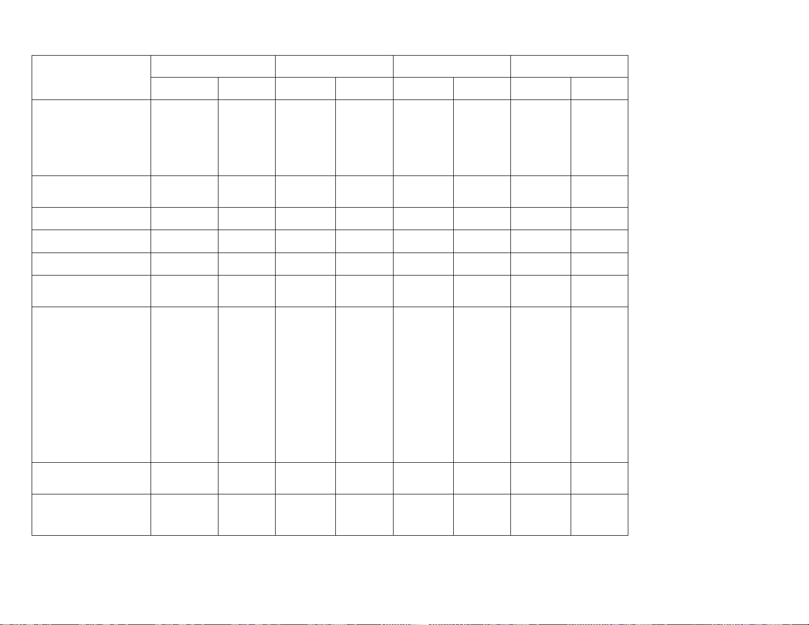
R11 (2x2) R11 (2 x 1-1/2) RD11 (2x2) RD11 (2x1-1/2)
MAXIMUM MINIMUM MAXIMUM MINIMUM MAXIMUM MINIMUM MAXIMUM MINIMUM
3600 RPM
3600 RPM
4858 RPM
4380 RPM
200 PSIG
(14 bar)
640 PSIG 225 PSIG 640 PSIG 225 PSIG 640 PSIG 225 PSIG 640 PSIG 225 PSIG
158 GPM 4 GPM 158 GPM 4 GPM 158 GPM 4 GPM 158 GPM 4 GPM
1.2 0.6 1.2 0.6 1.2 0.6 1.2 0.6
75 HP
(55 kw)
180° F
(82° C)
250° F
(121° C)
---
NPSHR
from Curve
(7)
Higher of
20° F (-7° C)
or fluid
freezing
temperature
4858 RPM
4380 RPM
4858 RPM
4380 RPM
200 PSIG
(14 bar)
75 HP
(55 kw)
180° F
(82° C)
250° F
(121° C)
---
NPSHR
from Curve
(7)
Higher of
20° F (-7° C)
or fluid
freezing
temperature
4858 RPM
4380 RPM
---
--(9)
90 PSIG
(6 bar) (10)
75 HP
(55 kw)
180° F
(82° C)
250° F
(121° C)
(with flush)
---
NPSHR
from Curve
15 HP
(11)
Higher of
20° F (-7° C)
or fluid
freezing
temperature
4858 RPM
4380 RPM
---
--(9)
90 PSIG
(6 bar) (10)
75 HP
(55 kw)
180° F
(82° C)
250° F
(121° C)
---
NPSHR
from Curve
15 HP
(11)
Higher of
20° F (-7° C)
or fluid
freezing
temperature
B. Operation Limits and Data (R11, RD11)
-Double Seal with cooled
flush
-Other Fluids:
First Critical Speed
Fluid Abrasives
---
---
18,000 RPM --- 18,000 RPM ---
100 PPM
Suspended
Solids
--- 100 PPM
275° F
(135° C) (5)
350° F
(177° C) (5)
Suspended
Solids
---
---
--- 100 PPM
Suspended
Solids
(14)
275° F
(135° C) (5)
350° F
(177° C) (5)
---
--- 100 PPM
Suspended
Solids
(14)
---
---
Footnotes: (Please see next page.)
15
Page 20

FOOTNOTES:
Consult factory for further information on the following:
(1) Materials and seals for charge pressure over 200 psig (14 bar)
(2) Specific gravities over 1.2 or below .6.
(3) Horsepower in excess of 300 (220 kw) for direct connect and 150 (112kw) for
belt drive.
(4) For input horsepower less than 25 (18 kw).
(5) Material, seals, o-rings, and required periphery equipment for temperatures over
250° F (135° C) and below 20° F (-7° C).
(6) Materials and pump components for increased abrasion resistance.
(7) For input horsepower less than 10 (7.5 kw).
(8) Seal flush and injection requirements: 2-3 GPM at 15-20 (1.03 – 1.4 BAR) psig
above suction pressure. Temperature of fluid dependent on required
temperature difference. Consult factory.
(9) Speed limitations by motor size.
(10) Suction pressure limitations by motor size.
(11) Minimum motor frame size for the RD11 pump.
(12) Speed limitations by bearing arrangement and pick-up tube selection.
(13) Speed limitations by bearing arrangement, pick-up tube selection and suction
pressure.
(14) Critical speed by motor frame size.
(15) Operation limits are NOT mutually exclusive.
(16) See performance curves for specific data.
C. BEFORE STARTING
The following procedures should be used when starting a new unit for the first time,
or after major maintenance has been performed.
16
Page 21
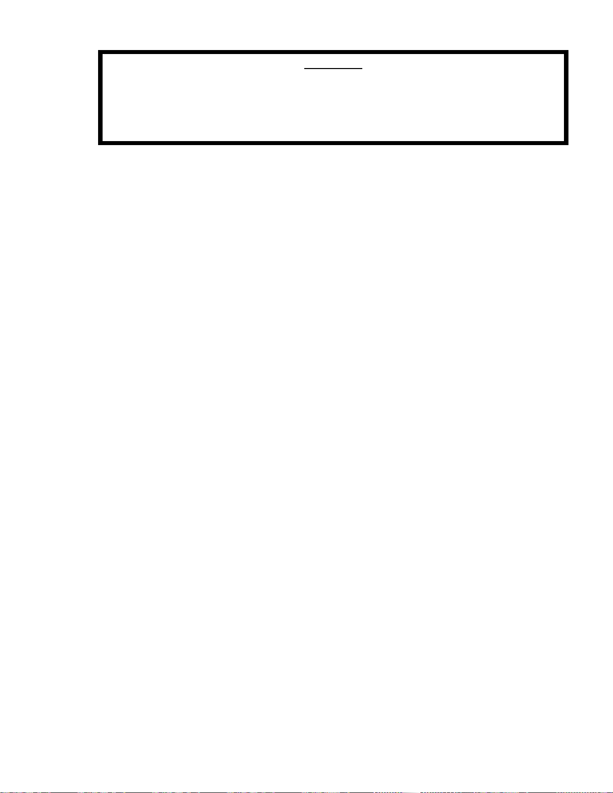
WARNING
WHEN CHECKING ALIGNMENT, OR PERFORMING ANY WORK ON THE UNITS,
ELECTRICAL SERVICE MUST BE LOCKED OUT WITH AN APPROVED
LOCKOUT AND KEY. FAILURE TO LOCKOUT EQUIPMENT MAY RESULT IN
INJURY.
1. Be sure that all installation requirements have been met and that the system
has been designed to keep the pump within its operating limits.
2. Rotate unit by hand to be sure that it turns freely.
3. Be sure pump and drivers are aligned.
4. Check bearing lubrication. The bearings in oil lubricated pumps should be
sprayed with small amount of oil before the initial pump start-up. Refer to
lubrication instructions in Part IV – Maintenance, Section F. Also verify that the
oil rings are in the proper location (refer to Disassembly/Assembly Manual,
Section Drawing 2.4).
5. Prime pump. The Roto-Jet pump is not a self-priming pump and may be
damaged if run dry. It must always be filled completely with liquid before
starting.
5.1 Be sure all valves in the suction line are fully open.
5.2 If the pump is installed with a positive head on the suction, prime by
opening the inlet valve while venting air out of discharge line.
5.3 If equipped with charge pump, prime by starting charge pump while
venting the discharge line until all air is out of the rotor.
6. Close discharge valve. (This should be done to reduce the load on the driver
during start-up and to provide a restriction.)
7. If equipped with seal flush, be sure all flush inlet valves are open so that liquid
can get to the seal.
8. Jog driver; check rotation. Counterclockwise when facing pump drive shaft.
9. Be sure all guards are installed on rotating parts.
17
Page 22
D. START-UP
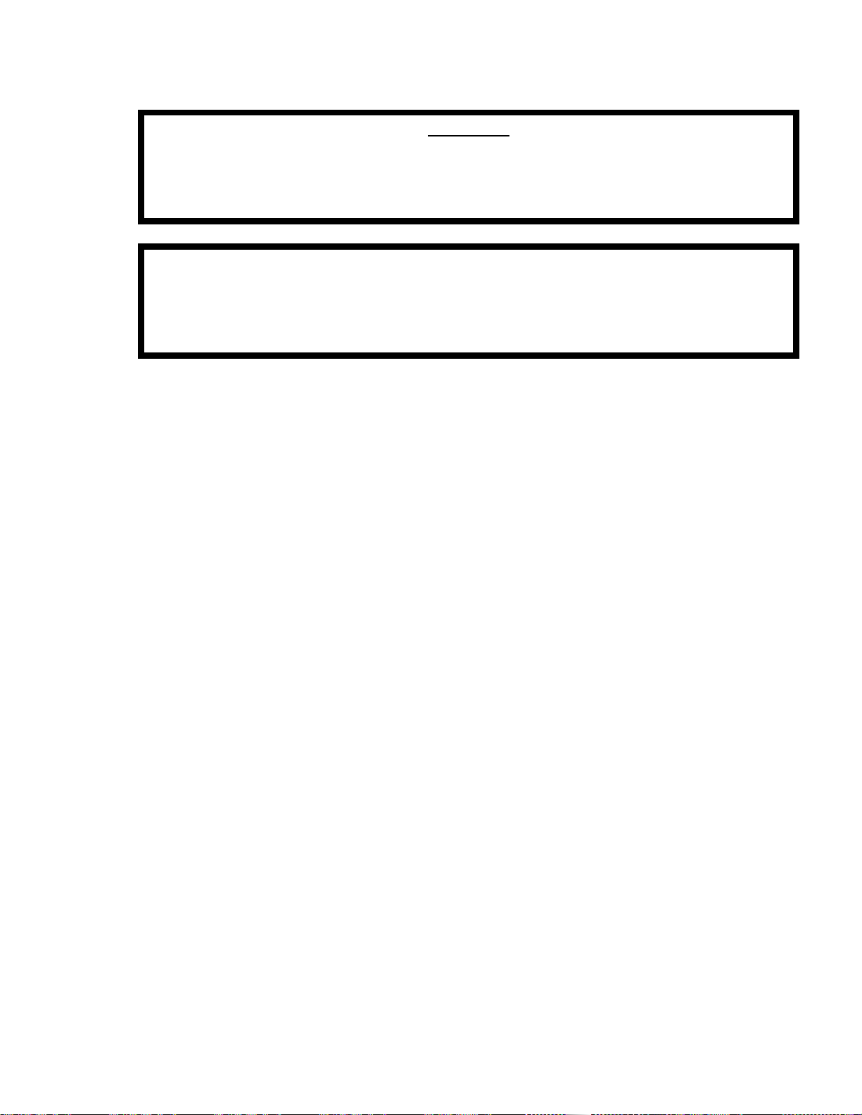
ALL GUARDS AND PROTECTIVE DEVICES MUST BE INSTALLED BEFORE
THE PUMP IS STARTED. CONTACT WITH UNGUARDED BELTS, SHEAVES,
OR COUPLINGS COULD RESULT IN INJURY.
DO NOT OPERATE PUMP WITH BOTH SUCTION AND DISCHARGE VALVES
CLOSED OR WITH SUCTION OR DISCHARGE CLOSED BY CLOGGING. THIS
COULD CAUSE DAMAGE AND IS DANGEROUS. ROTO-JET PUMPS ARE TO
BE USED FOR LIQUID SERVICE ONLY. EXCESS PRESSURE CAN CAUSE
MALFUNTION LEADING TO INJURY.
1. Start driver and bring unit up to speed.
2. Slowly open discharge valve until operating point is reached.
3. Check bearings during first hour of operation to be sure that they are operating
correctly. (Bearing temperatures should not exceed 180° F (82° C) for ambient
pumping temperatures.)
E. OPERATING CHECKS
1. Check the pump and piping to assure that there are no leaks.
2. Check and record inlet and discharge pressure gauge readings for future
reference.
3. Check and record voltage, amperage per phase and KW if an indicating
wattmeter is available.
4. Note any unusual noise or vibration.
F. OPERATING CAUTIONS
1. Belt and coupling guards must always be in place during operation.
2. In cold weather, the fluid in the pump and piping must be kept from freezing.
3. The pump must always be primed before starting or the mechanical seal may
be damaged.
4. Repeated trial starts may overheat the driver; allow sufficient time between
starts for heat to dissipate from motor windings.
5. The pump must always be operated within its design limits.
WARNING
18
Page 23
6. All pressure and flow adjustments must be made with the discharge valve;
7. Do not operate near shutoff (low flow) without a bypass.
8. Do not operate pump with suction valve closed – this will cause damage and is
G. SHUTDOWN
1. Close discharge valve. (Prevents reversal or continuation of flow after shutoff.)
2. Stop pump.
3. Close valves to prevent flow through by-pass, if applicable.
4. If pump is to remain out of service more than 2 weeks, follow the storage
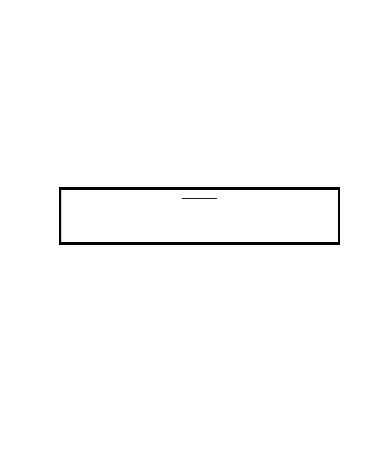
TO PREVENT PUMP FROM FREEZING DURING COLD WEATHER THE LIQUID
IN THE ROTOR ASSEMBLY MUST BE DRAINED. FAILURE TO REMOVE THE
LIQUID DURING FREEZING TEMPERATURES COULD RESULT IN SEVERE
DAMAGE TO THE PUMP.
never use a valve on the suction side of the pump for this purpose.
dangerous.
instructions in section I E. “Storage Instructions”.
WARNING
5. For long-term pump storage in cold temperatures drain the liquid in the rotor
assembly by doing the following:
5.1 Remove the ¾ NPT pipe plug in the endbell.
5.2 Rotate the pump until one of the rotor cover drain plugs lines up with the
¾ NPT hole in the endbell.
5.3 Remove the rotor cover drain plug and allow the liquid to completely
drain out.
5.4 Inspect and replace if necessary the o-ring on the rotor cover drain plug.
5.5 Reinstall the rotor cover drain plug in the rotor cover. Torque to 13 ft.
lbs. (18 N.M.).
5.6 Reinstall the 3/4 NPT plug in the endbell.
19
Page 24
5.7 Prior to starting the pump follow the steps in Section III, B, “Before
WHEN PERFORMING EQUIPMENT MAINTENANCE OR IF THE PUMP IS TO
REMAIN OUT OF SERVICE FOR A PERIOD OF TIME, THE EQUIPMENT
ELECTRICAL SERVICE MUST BE LOCKED OUT WITH AN APPROVED
LOCKOUT AND KEY. FAILURE TO LOCKOUT EQUIPMENT MAY RESULT
IN INJURY.
IV. MAINTENANCE
A. GENERAL
Operating conditions vary so widely that to recommend one schedule of
preventative maintenance for all Roto-Jet Pumps is not possible. Yet some sort of
regular inspection must be planned and followed. We suggest a permanent record
be kept of the periodic inspection and maintenance performed on the pump. This
recognition of maintenance procedure will keep your pump in good working
condition, and prevent breakdowns. A suggested form for recording pump
maintenance is provided at the end of this manual.
One of the best rules to follow in the proper maintenance of your Roto-Jet Pump is
to keep a record of actual operating hours. Then, after a predetermined period of
operation has elapsed, the pump should be given a thorough inspection. The length
of this operating period will vary with different applications, and can only be
determined from experience. New equipment, however, should be examined after a
relatively short period of operation. The next inspection can be lengthened
somewhat. This system can be followed until a maximum period of operation is
reached, which should then be considered the operating schedule between
inspections.
The maintenance timetable on the following page may be used as a guide.
Starting”.
WARNING
20
Page 25
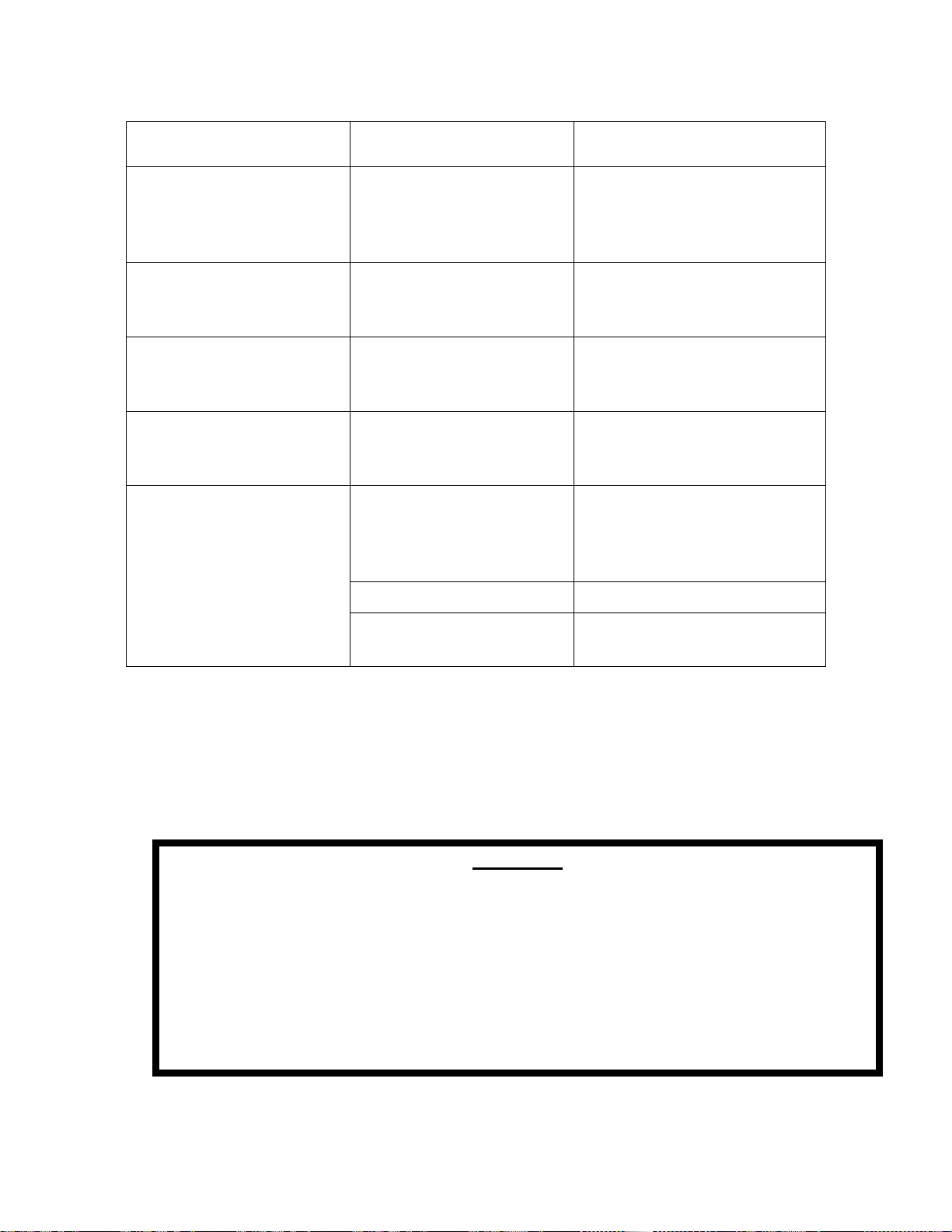
B. MAINTENANCE TIMETABLE
SCHEDULE
TIME
MAINTENANCE
RG, 2100 & RD11
MAINTENANCE
RO, ROH, R11 & 2200
Daily Operating conditions
pressure, Flow, Seal
leakage, Vibration
Operating conditions
pressure, Flow, Seal
leakage, Vibration –
Oil level
1500 hours/3 months;
whichever occurs first
Lubricate bearings 1.oz.
(.03 L). Grease to each
fitting
4000 hours/6 months;
whichever occurs first
Annually Disassemble, clean and
As Required Replace seals;
Check Belts on B suffix
models or drive on A
suffix models
inspect pump, replace
parts as necessary
maximum allowable
leakage is: 1 pint per
Change bearing oil.* Check
belts on B-suffix models or
drive on A-suffix models
Disassemble, clean and
inspect pump, replace parts
as necessary
Replace seals; maximum
allowable leakage is: 1 pint
per hour (0.5 l)
hour (0.5 l)
Clean strainer Clean strainer
Adjust or replace drive
belts B-suffix models
Adjust or replace drive belts
B-suffix models.
*Oil incompatibility may cause bearing failure.
C. V-BELT DRIVE
Drive should be checked for tension and alignment during the first few days of
operation, and periodically thereafter.
WARNING
WHEN CHECKING ALIGNMENT OR PERFORMING ANY WORK ON THE UNITS,
ELECTRICAL SERVICE MUST BE LOCKED OUT WITH AN APPROVED
LOCKOUT AND KEY. FAILURE TO LOCKOUT EQUIPMENT MAY RESULT IN
INJURY.
ALL GUARDS AND PROTECTIVE DEVICES MUST BE INSTALLED BEFORE
THE PUMP IS STARTED. CONTACT WITH UNGUARDED BELTS, SHEAVES,
OR COUPLINGS COULD RESULT IN INJURY.
21
Page 26

To replace belts:
1. Lockout electrical to motor.
2. Remove belt guard.
3. Slack off belt tension and remove belts.
4. Inspect sheaves for wear or damage.
5. Install new belts.*
6. Replace belt guard.
*NOTE: When belts are replaced they must be replaced as a set.
D. STRAINER
The filter or strainer in the suction piping should be inspected and cleaned
periodically. Failure to do so could cause a restriction in the inlet flow, resulting
pump cavitation or failure of the strainer.
E. MECHANICAL SEAL
The mechanical seal provided in the pump requires no maintenance or operational
adjustment. When the seal becomes worn or damaged and leaks excessively, it
must be replaced.
The mechanical seal is a precision product; therefore, treat it with care. In handling,
do not scratch the face of the seal or mating ring or let it drop, and take particular
care not to scratch the lapped face that comes in contact with the seal mating ring.
Cleanliness is of great importance, particularly at the seal faces.
The seal faces “wear in” with respect to each other and if disturbed it may be
possible to reseat them. It is good practice to maintain a spare seal kit and replace
the seal and the seal mating ring as a set.
The seal faces should be inspected for abnormal wear patterns. Seals should never
be immersed in solvent of any kind as this could damage this internal o-ring.
F. BEARING LUBRICATION
1. OIL LUBRICATED
1.1 Factory Lubrication:
The pedestal is filled with oil and test run at the factory.
1.2 Approved Oil:
Mobil Delvac 1 ESP 5W-40 Synthetic Oil.
22
Page 27
1.3 Capacity:
RO, ROH – Approximately 6 quarts (5.7 L)
R11 – Approximately 2 quarts (1.9 L)
2200 – Approximately 4 quarts (3.8 L)
1.4 Oil change schedule:
NOTE: Recommend using a 13/16” 8 point socket to remove the oil
drain plugs.
See maintenance timetable in Section IV, B.
The schedule time intervals should be shortened for conditions of dust,
dirt and moisture.
CAUTION: Do not mix oils. Oil incompatibility may cause bearing
failure.
2. GREASE LUBRICATED (RG)
2.1 Factory Lubrication:
The bearings are packed with grease at the factory and ordinarily will
require no attention before starting provided the pump has been stored
in a clean, dry place prior to its first operation.
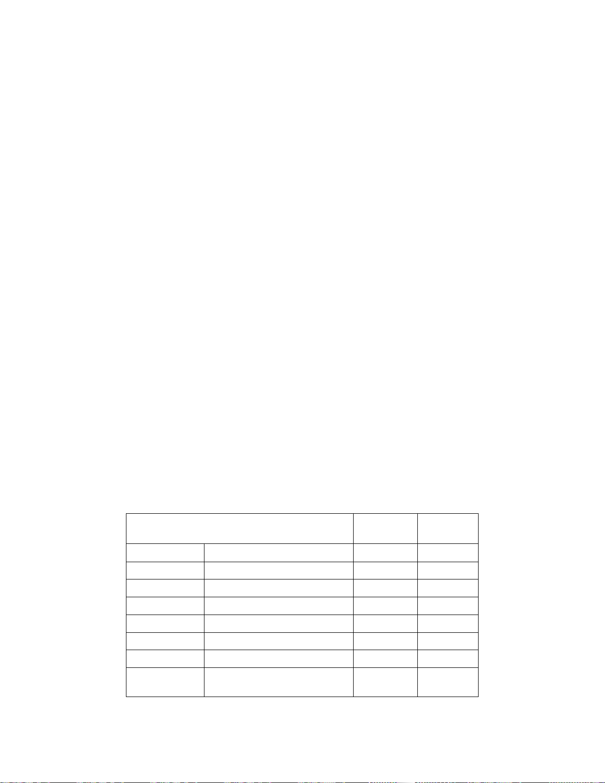
2.2 Approved Greases
Do not use any grease that is not listed unless it is approved by the
factory. Failure to comply may result in voiding the warranty.
2.3 Approved Substitute Greases for SRI No. 2.
NOTE: The pump is lubricated at the factory with Chevron SRI No. 2.
APPROVED GREASE BASE
MATERIAL
Chevron
Chevron BRB No. 2 Polyurea 2
Exxon & Esso UNIREX No. 2 Lithium 2
Texaco RB Lithium 2
Amoco Rykon Premium 2 Lithium 2
Mobil Mobilith 22 Lithium 2
Shell Albida LC EP2 Lithium 2
Royal Purple Ultra Performance Aluminum
SRI No. 2 (Preferred Grease)
Polyurea 2
Complex
NLGI NO.
2
CAUTION: DO NOT MIX GREASES. GREASE INCOMPATIBILITY
MAY CAUSE BEARING FAILURE.
23
Page 28

G. BEARING SYSTEM
Bearings should be inspected for smooth rotation and signs of pitting, rust or metal
bluing. Bearings should be replaced as a complete set.
The bearing spacer set located between the radial and the thrust bearing is
designed to effectively transmit the pump loads to the pedestal. Scoring, rust or
debris on the spacer surfaces may affect the life of the bearings. It is recommended
that the bearing spacer set be replaced when the bearings are replaced.
It is considered good practice to replace the wave spring when replacing the
bearings as conditions may have affected the temper of the spring.
The bores inside of the pedestal should be inspected for scoring, pitting, rust or
debris.
The purpose of the bearing shims is to insure proper preload of the bearings and
adequate seal compression. The correct number of shims are identified and
installed at the factory. When major components such as rotor, rotor cover, or drive
shaft are replace, the quantity of shims required may vary.
H. ROTOR AND ROTOR COVER
To alleviate vibration damage, the rotor, rotor cover and drive shaft are assembled
and balanced at the factory. Unless otherwise specified, the assembly is balanced
for fluid of specific gravity of 1.0. Other applications may require rebalancing of the
rotating assembly. Excessive material removal due to erosion, corrosion, or
damage may also affect the balance of the pump. The rotor and rotor cover should
be inspected for signs of cavitation damage. If damage is evident, the cause should
be identified and eliminated. The inner shroud of the rotor cover contains a lip that
form parts labyrinth seal. This lip should be inspected for excessive wear. The flow
passages in the rotor cover should be inspected for excessive wear. The flow
passages in the rotor cover should be inspected for blockage.
I. PICK-UP TUBE
The condition of the pick-up tube will affect the successful operation of the pump.
For optimum operation, the pick-up tube must be free of blockage and the inlet must
be smooth and free of damage due to erosion or mishandling. When the pick-up
tube is replaced, it is recommended that the (8) socket head capscrews (RG, RO) or
the lock-nut (R11, RD11, 2100 & 2200) also be replaced.
24
Page 29
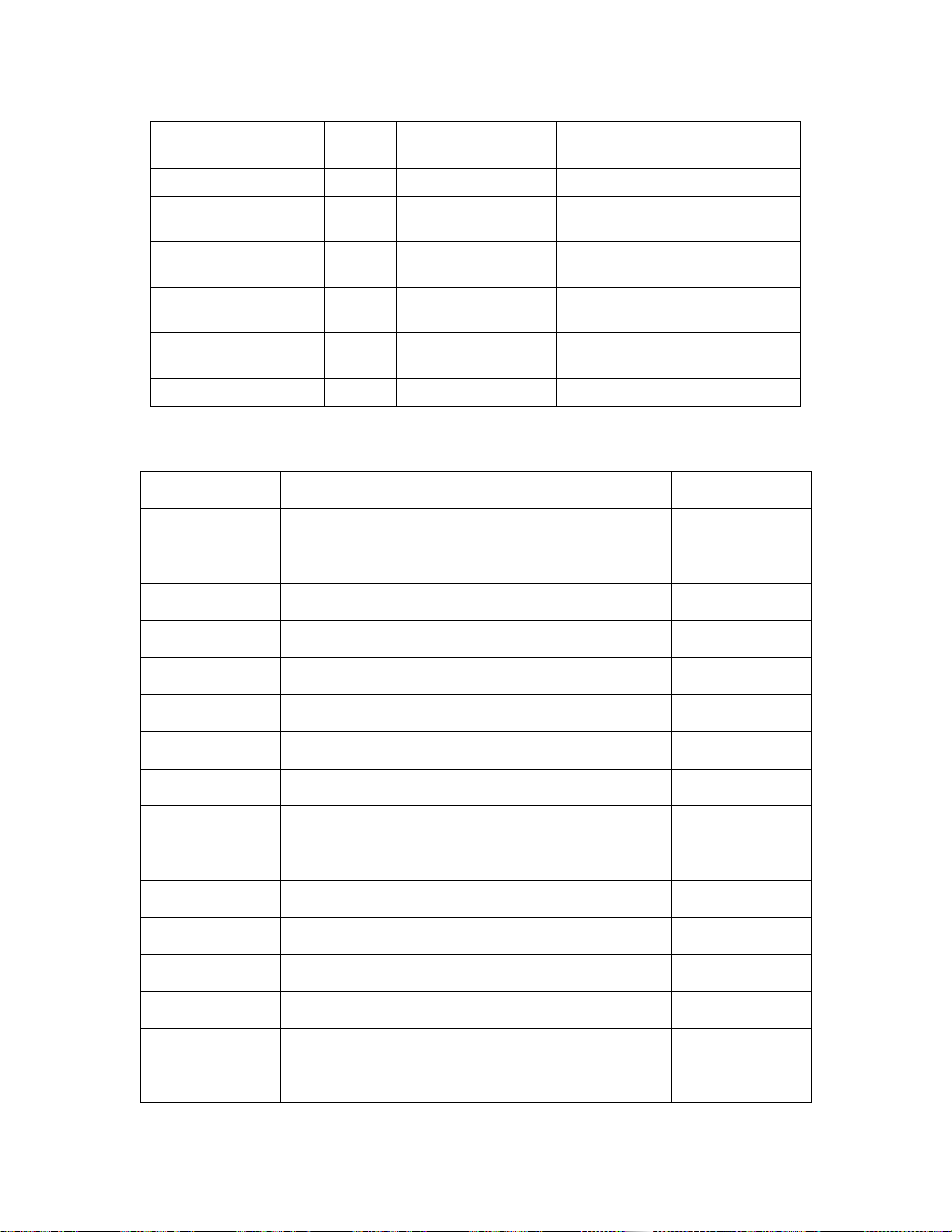
J. OPERATING MAINTENANCE RECORDS
ITEM UNITS DESIGNED
VALUE
1. Pump Speed RPM
2. Pump Discharge
Pressure
3. Flow GPM
4. System Pressure PSI
5. Inlet Pressure PSI
6. Fluid Temperature °F (°C)
PSI
(BAR)
(M3/hr)
(BAR)
(BAR)
ACTUAL
VALUE
DATE MAINTENANCE PERFORMED BY
BY
25
Page 30
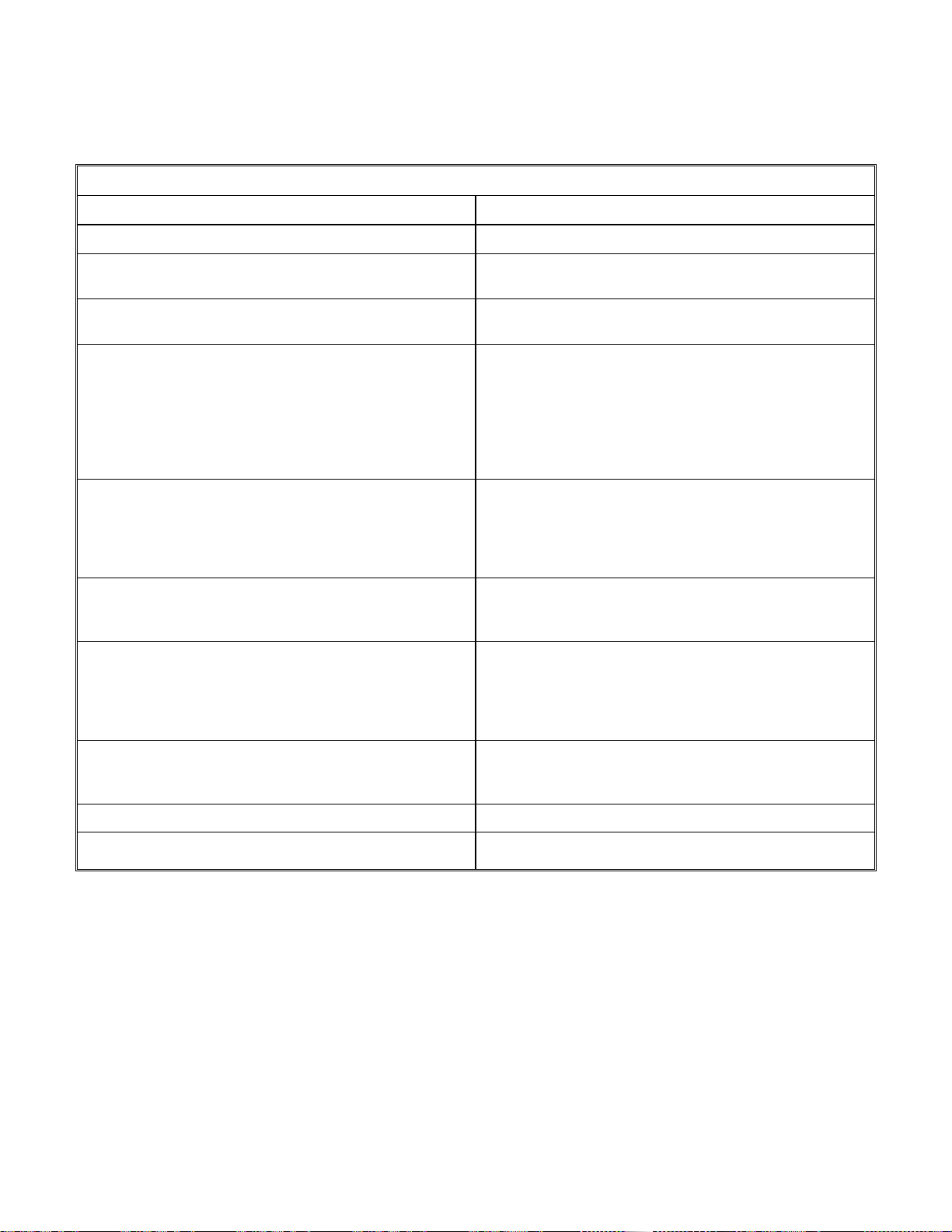
V. TROUBLESHOOTING
A.
NO LIQUID DELIVERED AT END DELIVERY POINT OR THROUGH FLOW METER
Possible Causes Corrective Action
1. Inlet or discharge valves closed Be sure all valves are fully opened.
2. Lack of prime. Fill pump and suction completely with liquid. Check for
vapor bind.
3. Obstruction in liquid passages. Dismantle pump and inspect passages of pick-up tube,
rotor cover and manifold. Remove obstruction.
4. System head too high. Total system head greater than head for which pump
designed. Check pipe friction losses. Larger piping
may correct condition. Are valves wide open? Increase
pump speed to develop greater differential pressure.
CAUTION – Brake HP of pump varies as the cube of
the speed; therefore, any increase in speed means
considerable increase in the power demand.
5. Suction Lift Too High If no obstruction at inlet, check for pipe friction losses.
However, static lift may be too great. Measure with
mercury column or vacuum gauge while pump
operates. If static lift is too high, liquid to be pumped
must be raised or pump lowered.
6. Air Leak in Suction Line Suction line can be tested by shutting off or plugging
inlet and putting line under pressure. A gauge will
indicate leak with a drop of pressure.
7. Speed Too Low. Slipping drive belts – check belt tension. Check drive
sheave and verify correct size for required speed.
Check whether motor is directly across-the-line and
receiving full voltage. Frequency may be incorrect,
motor may have an open phase.
8. Wrong Rotation. Check motor rotation with required pump rotation.
Pump rotation is clockwise viewed from the manifold
end of pump.
9. Suction or Discharge Line Plugged. Unplug line.
10. Gas or Vapor Pocket in Suction Line. Provide gas separation chamber on suction line.
26
Page 31
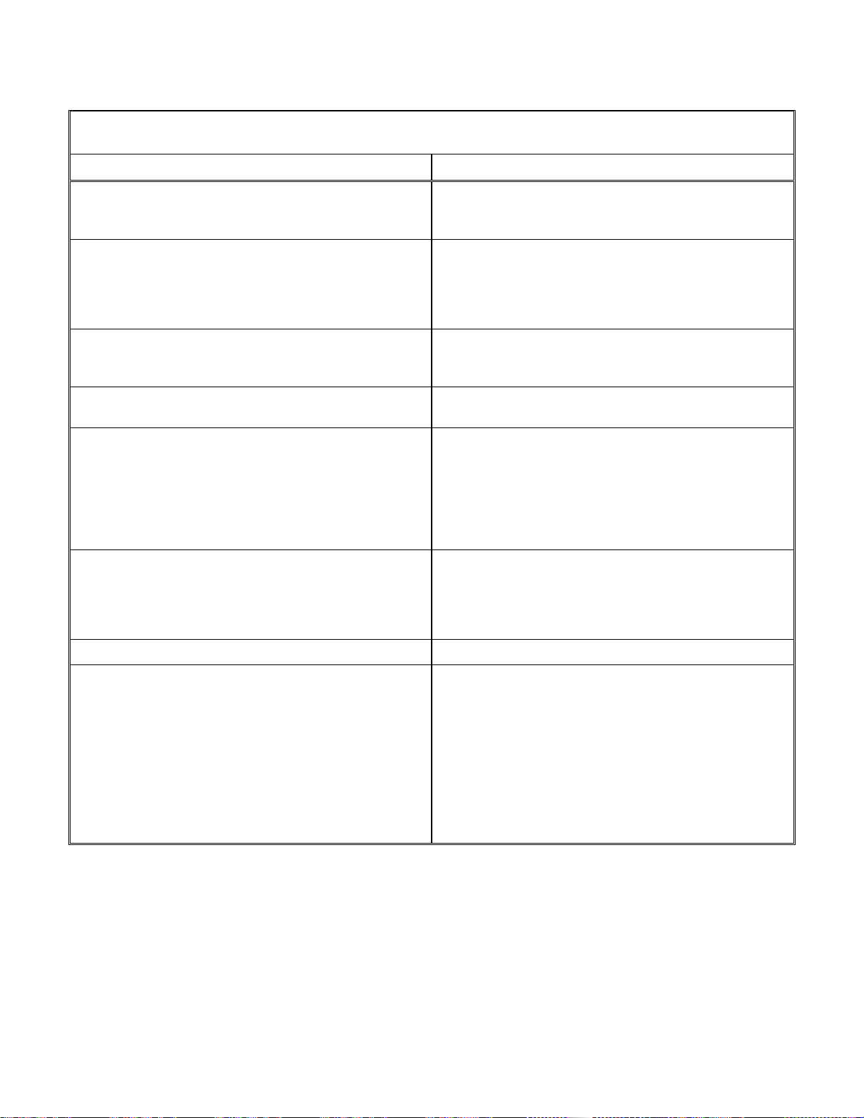
B.
NOT ENOUGH LIQUID DELIVERED AT END DELIVERY POINT
OR THROUGH FLOW METER
Possible Causes Corrective Action
1. Air Leak in Suction Line. Suction line can be tested by shutting off or plugging
inlet and putting line under pressure. A gauge will
indicate a leak with a drop of pressure.
2. Speed Too Low. Slipping drive belts – check belt tension. Check driver
sheave and verify correct size for required speed.
Check whether motor is directly across-the-line and
receiving full voltage. Frequency may be incorrect,
motor may have an open phase.
3. Wrong rotation. Check motor rotation with required pump rotation.
Pump rotation is clockwise viewed from manifold end of
pump.
4. Obstruction in Liquid Passages. Dismantle pump and inspect passages of pick-up tube,
rotor cover and manifold. Remove obstruction.
5. Discharge Head Too High. Total system head greater than head for which pump
designed. Check pipe friction losses. Larger piping
may correct condition. Are valves wide open? Increase
pump speed to develop greater differential pressure.
CAUTION – Brake HP of pump varies as the cube of
the speed; therefore, any increase in speed means
considerable increase in power demand.
6. Suction Lift Too High. If no obstruction at inlet, check pipe friction losses.
However, static lift may be too great. Measure with
mercury column or vacuum gauge while pump
operates. If static lift is too high, liquid to be pumped
must be raised or pump lowered.
7. Suction or Discharge Line Partially Plugged. Unplug line.
8. Inlet Cavitation. Insufficient NPSH (Net Positive Suction Heat) available.
Available NPSH must always equal or exceed the
required NPSH of the pump. Depending on installation:
A. Increase inlet pressure to pump.
B. Reduce inlet pipe friction losses.
C. Increase height of suction vessel.
D. Pressurize suction vessel.
E. Lower the pump.
27
Page 32
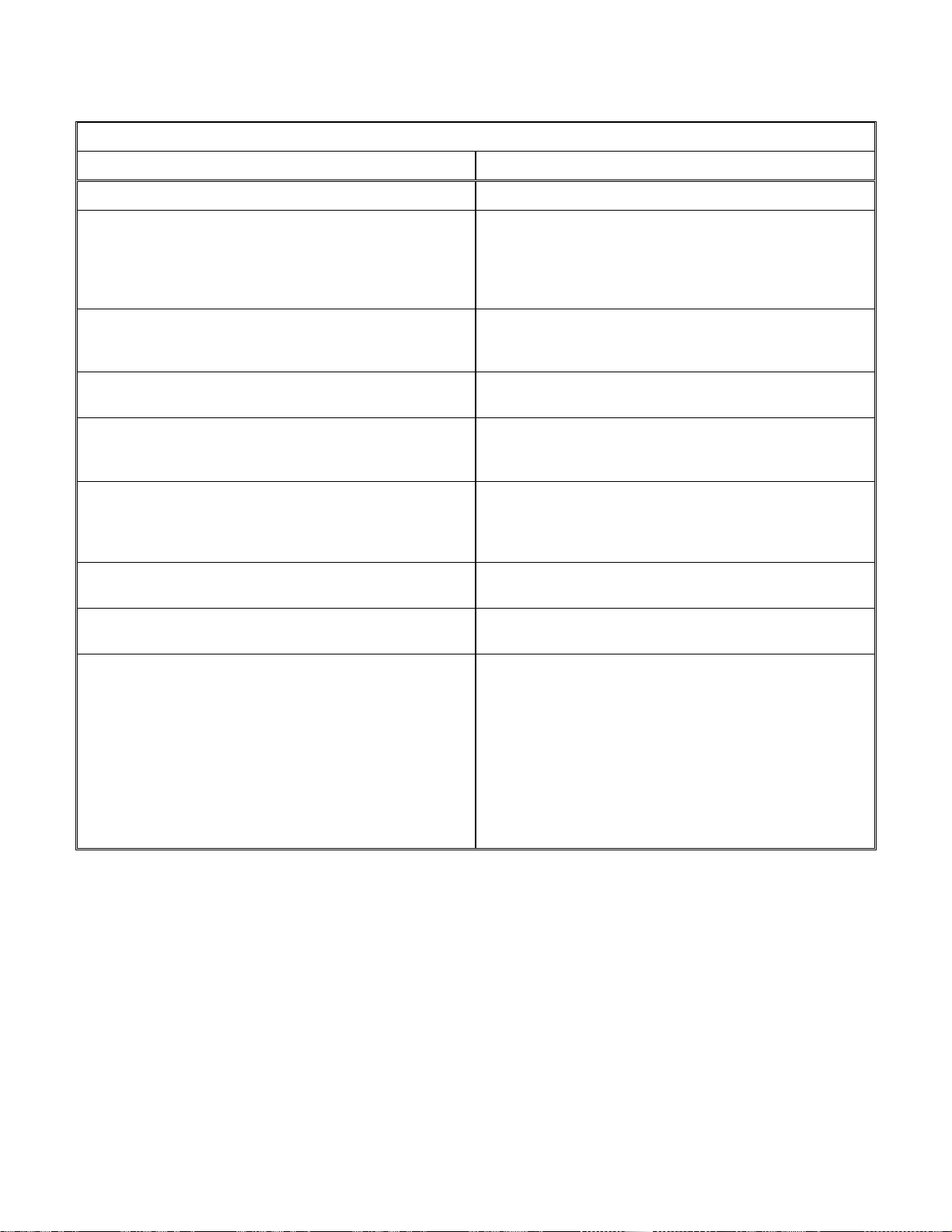
C.
NOT ENOUGH PRESSURE ON PRESSURE GAUGE
Possible Causes Corrective Action
1. No Restriction on Pump Discharge. Close valve on discharge side at start up.
2. Speed Too Low. Slipping drive belts – check belt tension. Check driver
sheave and verify correct size for required speed.
Check whether motor is directly across-the-line and
receiving full voltage. Frequency may be incorrect,
motor may have an open phase.
3. Wrong rotation. Check motor rotation with required pump rotation.
Pump rotation is clockwise viewed from manifold end of
pump.
4. Obstruction in Liquid Passages. Dismantle pump and inspect passages of pick-up tube,
rotor cover and manifold. Remove obstruction.
5. Air Leak in Suction Line. Suction line can be tested by shutting off or plugging
inlet and putting line under pressure. A gauge will
indicate a leak with a drop of pressure.
6. Air or Gases in Liquid. May be possible to over rate pump to point where it will
provide adequate pressure despite condition. Better to
provide gas separation chamber on suction line near
pump.
7. Head Lower Than Rating, Pumps Too Much Liquid Pump may be operating at a higher flow rate than
suspected. Throttle pump at discharge to reduce flow.
8. Pick-up Tube Damaged. Dismantle pump and inspect pick-up tube for erosion or
damage.
9. Inlet Cavitation. Insufficient NPSH (Net Positive Suction Head)
available. Available NPSH must always equal or
exceed the required NPSH of the pump. Depending on
installation:
A. Increase inlet pressure to pump.
B. Reduce inlet pipe friction losses.
C. Increase height of suction vessel.
D. Pressurize suction vessel.
E. Lower the pump.
28
Page 33

D.
PUMP OVERLOADS DRIVER
Possible Causes Corrective Action
1. Speed too high.. Check driver and verify correct size for required speed.
2. Specific gravity too high. Check. This can cause overloading.
3. Head lower than rating, pumps too much liquid.. Pump may be operating at a higher flow rate than
suspected. Throttle pump at discharge to reduce flow.
4. High viscosity. Check. This can cause high drag on the rotor, rotor
cover and pick-up tube.
5. Electrical defects. The voltage and frequency of the electric motor may be
lower than that for which the motor was built. The
motor may not be ventilated properly due to a poor
location.
E.
PUMP WORKS FOR A WHILE THEN QUITS
Possible Causes Corrective Action
1. Incomplete priming Free pump, piping and valves of all air. If high points in
suction line prevent this, they need correcting.
2. Suction lift too high. If no obstruction at inlet, check for pipe friction losses.
However, static lift may be too great. Measure with
mercury column or vacuum gauge while pump
operates. If static lift is too high, liquid to be pumped
must be raised or pump lowered.
3. Air leak in suction line. Suction line can be tested by shutting off or plugging
inlet and putting line under pressure. A gauge will
indicate a leak with a drop of pressure.
4. Air or gases in liquid. May be possible to over rate pump to point where it will
provide adequate pressure despite condition. Better to
provide gas separation chamber on suction line near
pump.
5. Mechanical failure of critical pump parts. Check bearings and pick-up tube for damage.
29
Page 34
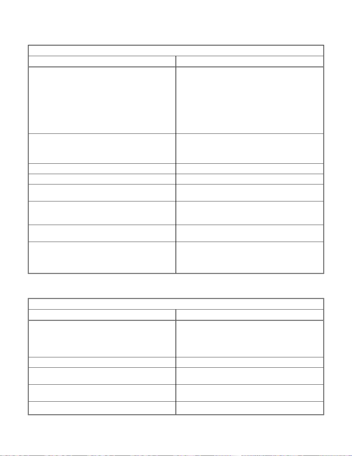
F.
PUMP VIBRATION
Possible Causes Corrective Action
1. Inlet cavitation. In sufficient NPSH (Net Positive Suction Head)
available. Available NPSH must always equal or
exceed the require NPSH of the pump. Depending on
installation:
A. Increase inlet pressure to pump.
B. Reduce inlet pipe friction losses.
C. Increase height of suction vessel.
D. Pressurize suction vessel.
E. Lower the pump.
2. Air or gases in liquid. May be possible to over rate pump to point where it will
provide adequate pressure despite condition. Better to
provide gas separation chamber on suction line near
pump.
3. Misalignment.. Check alignment and tension of V-belts.
4. Mechanical failure of critical pump parts. Check bearings and pick-up tube for damage.
5. Obstruction in liquid passages. Dismantle pump and inspect passages of pick-up tube,
rotor cover and manifold. Remove obstruction.
6. Foundation not rigid. The foundation must be rigid enough to support the
pump, auxiliary equipment, drive and baseplate, and
prevent vibration and misalignment during operation.
7. Foreign particles in rotor. The accumulation of foreign particles in the rotor may
create and unbalanced condition. Clean pump rotor.
8. Erosion of rotor. Check pump rotor for evidence of erosion..
Displacement of metal within rotor could create an
unbalanced condition. Rebalance or replace rotor
assembly.
G.
BEARINGS OVERHEAT OR WEAR RAPIDLY
Possible Causes Corrective Action
1. Improper lubrication or bearing pre-load. A. Make sure bearings are installed properly.
B. Remove pedestal cover and verify that the oil rings
are in the proper location. Reference
Disassembly/Assembly Manual, Section Drawing
2.4.
2. Vibration. See Vibration Troubleshooting Section.
3. Dirt or water in bearings. Dismantle pump and clean bearing housing. Replace
bearings and lubricate.
4. Bearings too tight. Check V-belt tension. Follow procedure outlined in
manufacturer’s manual.
5. High suction pressure.. Inlet pressure appreciably different than specified.
30
Page 35

H.
LIQUID RUNS FROM DRAIN HOLE
Possible Causes Corrective Action
1. Seal leaking. Dismantle pump and inspect seal faces. Replace as
necessary.
2. Leakage past o-rings. Dismantle pump, clean and inspect o-ring grooves.
Inspect o-rings. Replace parts as necessary.
I.
NOISE
Possible Causes Corrective Action
1. Vibration. See Vibration Troubleshooting section.
2. Inlet cavitation. In sufficient NPSH (Net Positive Suction Head)
available. Available NPSH must always equal or
exceed the require NPSH of the pump. Depending on
installation:
F. Increase inlet pressure to pump.
G. Reduce inlet pipe friction losses.
H. Increase height of suction vessel.
I. Pressurize suction vessel.
Lower the pump.
3. Discharge cavitation. Decrease flow requirements; increase pump discharge
pressure.
4. Belts slipping. Adjust or replace belts.
5. Turbulence in discharge piping. A. Fully open the discharge valve.
B. Increase the pipe diameter.
C. Eliminate sharp bends in the piping.
VI. PARTS
A. SPARE PARTS LIST
Quantity
1. Bearing Kit 1
2. Seal Kit 1
3. Pick-up Tube Replacement Kit 1
4. O-ring kit 1
5. Pedestal Gasket (RO and 2200 only) 1
6. Rotor Cover Drain Plug 2
31
Page 36

B. ORDERING PARTS
General – It is Roto-Jet Pump’s policy to continually improve its products.
Therefore, specifications are subject to change without notice. Parts should be
ordered as far in advance or their use as possible since circumstances beyond our
control may reduce existing stock.
Placing Orders – The satisfactory ordering and receiving of parts is dependent
upon specific and correct information supplied by the purchaser. A specification
sheet for each unit manufactured is on file at the factory, and in case some special
part is needed, it can be provided if the correct model and serial number is given.
Many unnecessary errors and delays may be eliminated by observing the following
instructions.
Your parts order should state:
1. Model and serial number of pump.
2. Part number, description, and quantity required.
3. Your company name, address and zip code clearly.
4. Specific shipping and billing instructions.
5. Date required.
With this assistance, the time required to expedite your order will be greatly reduced.
NOTE: Parts will be furnished in original materials unless specified as a material
change. All material substitutions should be discussed with the factory.
C. ASSISTANCE
Should you need any assistance, contact the factory or nearest regional office listed
on the back cover.
32
Page 37
For optimum service and technical assistance,
please contact our factory for the distributor or representative
nearest to your project:
Weir Specialty Pumps
440 West 800 South
Salt Lake City, UT 84101
(P.O. Box 209, 84110-0209)
Tel 801-359-8731
Fax 801-530-7828
www.weirpowerindustrial.com
Excellent
Engineering
Solutions
Specification in this manual are subject to change without prior notification. Manual # RJ-DA-9 (01/13)
1994-2013
 Loading...