

Page 1
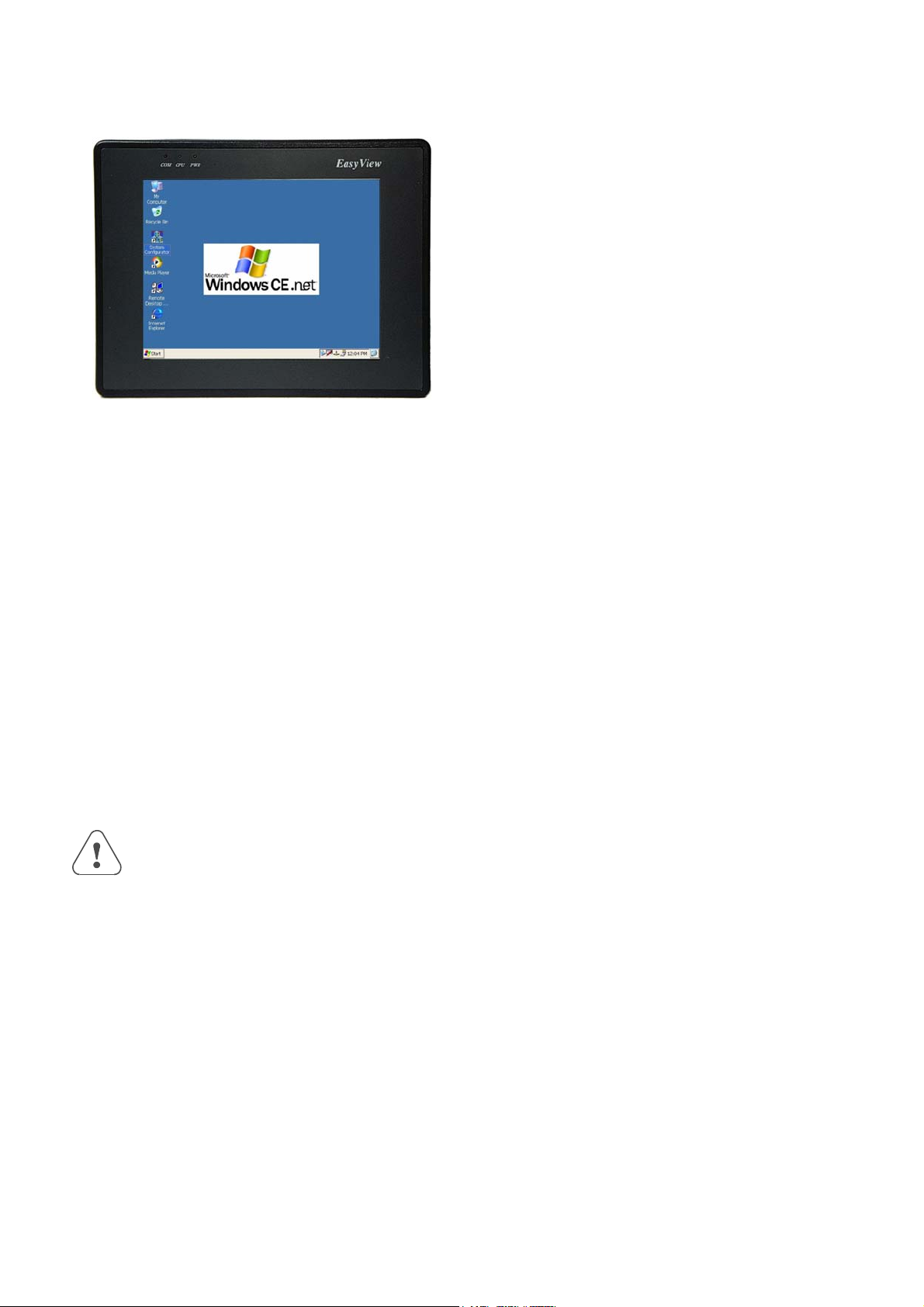
MT-600 series
MT-608S
Installation Instruction
1.0 Installation and Startup Guide
Install Environment
Where
Used
NEMA
Rating
Electrical
Environment
Mechanical
Environment
The MT-600 Series is designed for industrial. The temperature range of operating is
from 32 to 113 °F (0 to 45 °C) , as majority of industrial environments. It may not be
suitable for using in certain outdoor applications. Please consult the factory for
advised usage in outdoor applications.
The MT-600 Series front bezel is NEMA 4 rated. When installed properly in a NEMA
4 panel, the NEMA 4 rating of the panel will not be compromised. This means that
fluids will not enter the panel during wash downs.
The MT-600 Series has been tested to conform to European CE requirements. This
means that the circuitry is designed to resist the effects of electrical noise. This does
not guarantee noise immunity in severe cases. Proper wire routing and grounding
will insure proper operation.
Avoid installing units in environments where severe mechanical vibration or shocks
are present.
2.0 Installation Instructions
2.1 Mounting Instructions
2.1.1 Location Considerations
Care should be taken when locating equipment behind the unit to ensure that AC power wiring, PLC
output modules, contactors, starters and relays, and any other source of electrical interference are located
away from the back of the unit.
Particular note should be taken to the position of variable speed drives and switching power supplies.
Their input and load cables should be screened to a central star earth point.
1
Page 2
2.1.2 Making a NEMA-4 Mounting
Panel
Details
The unit can be mounted into panels with a depth of 4”(105mm). It is recommended that
the unit be mounted on the front panel of a steel enclosure, through an appropriate
opening*. Allow a clearance of 1”(25mm) around the sides of the unit for mounting
hardware. Allow clearance for cable connections to the back of the unit. Unit depth may
vary according to cable type used. Typically, plan a depth to accommodate at least
4”(105mm) behind the panel.
NEMA-4
Mounting
Put the unit through the panel cut out. Slide the clamps into the 6 holes provided around
the case. Tighten the clamping screws in an even pattern until the unit is secured in the
panel.
Caution!
Note:
Do not over tighten mounting clamps!
Specifications
Note: To seal to NEMA-4 specifications, all supplied mounting clamps must be used and
panel cannot flex more than 0.010”.
2.1.3 Environmental Considerations
z The MT-600 are to be used indoors as built in displays. Make sure that the displays are
installed correctly and that the operating limits are followed (See Specifications).
z Do not operate the unit in areas subject to explosion hazards due to flammable gases,
vapors or dusts.
z The unit should not be installed where fast temperature variations and/or high humidity
are present. This will cause condensation of water in the device.
z Do not install these terminals in environments where have inflammable gases.
2.2 Power Connections
Make sure that all local and national electrical standards are met when the installing the unit.
Contact your local authorities to determine which codes apply.
2.2.1 Power Requirements
Power
The MT-600 can be powered by DC power only. The specified voltage range
is +21 to 25 Volts DC. This insures compatibility with most controller DC
systems.
The power conditioning circuitry inside the unit is accomplished by a
switching power supply. The peak starting current can be as high as 700mA.
Fusing
Requirements
If the display does not come on within 2 seconds of power up, remove
power. An internal fuse will prevent damage if the polarity of the DC power
is incorrect. Check wiring to insure proper connections and try to power up
Caution
High Voltage
again.
An Internal fuse will prevent damage for over voltage condition however it
isn’t guaranteed.
DC voltage sources should provide proper isolation from main AC power
and similar hazards.
Caution
Emergency
A Hard-wired EMERGENCY STOP should be fitted in any system using an
MT-600 to comply with ICS Safety Recommendations.
Stop
2
Page 3
Caution
Supply Voltage
Condition
Do not power the MT-600 and inductive DC loads, or input circuitry to the
controller, with the same power supply. Note: The 24 VDC output from
some controllers may not have enough current to power the MT-600.
Caution
Wire Routing
Wire lengths should be minimized (Maximum 1600’ (500 m) shielded,
1000’ (300 m) unshielded).
Wires should be run in pairs with a neutral or common paired with a hot or
signal line.
If wiring is to be exposed to lightning or surges, use appropriate surge
suppression devices.
Keep AC, high energy, and rapidly switching DC wiring separate from
signal wires.
Equip ungrounded DC supplies with a resistor and capacitor in parallel to
earth ground. This provides a path for static and high frequency dissipation.
Typical values to use are 1MOhm and 4700pF.
Connection
To make a connection, strip about 3/8” of insulation off the end of the wire,
turn the connector screw counterclockwise until the gap is wide open, insert
the wire all the way in, and turn the screw clockwise until it’s tight.
Connect positive DC line to the ‘+24V’ terminal and the DC ground to the
‘0V‘ terminal.
2.2.2 Grounding Requirements
Chassis ground must be used. DC ground is not directly coupled to Earth
ground internally. It is preferable not to ground DC negative return to chassis
ground as poor site earths can introduce noise into a system, but if necessary
an earth connection should be made, from the power supply return point to
the central star earth point. Ground conductors should be as short and as large
in size as possible. The conductors must always be large enough to carry the
maximum short circuit current of the path being considered. Ground
conductors should be connected to a tree from a central star earth ground
point. This ensures that no ground conductor carries current from any other
branch.
2.2.3 CE Requirements
To make an MT-600 comply with EMC directives, and to reduce susceptibility to electrical
interference, a separate #14 AWG ground wire should be taken to the chassis ground terminal of the
power connector. This ground connection should be run directly to the central star earth connection
point (as recommended in most Installation Instructions).
2.2.4 Safety Guidelines
This section presents recommended installation practices, and procedures. Since no two
applications are identical, these recommendations should be considered as guidelines.
Hardware
Considerations
WARNING!
The system designer should be aware that devices in Controller systems could
fail and thereby create an unsafe condition. Furthermore, electrical
interference in an operator interface, such as an MT-600, can lead to
equipment start-up, which could result in property damage and/or physical
injury to the equipment operator.
If you, or your company, use any programmable control systems that require
an operator or attendant, you should be aware that this potential safety hazard
exists and take appropriate precautions. Although the specific design steps
depend on your particular application, the following precautions generally
apply to installation of solid-state programmable control devices. In addition,
these precautions conform to the guidelines for installation of Controllers as
recommended in the NEMA ICS 3-304 Control Standards.
Programming
To conform with ICS Safety Recommendations, checks should be placed
3
Page 4
Considerations
in the controller to ensure that all writable registers that control critical
parts of plant or machinery have limit checks built into the program, with
an out-of-limit safe shut down procedure to ensure safety of personnel.
ICS 3-304.81 Safety Recommendations:
Consideration should be given to the use of an emergency stop function, which is independent of the programmable
controller.
Where the operator is exposed to the machinery, such as in loading or unloading a machine tool, or where the machine
cycles automatically, consideration should be given to the use of an electromechanical override or other redundant means,
independent of the programmable controller, for starting and interrupting the cycle.
If provision is required for changing programs while the equipment is in operation, consideration should be given to the
use of locks or other means of assuring that only authorized personnel can make such changes.
These recommendations are intended as safeguards against the failure of critical components and the effects of such
failures or the inadvertent errors that might be introduced if programs are changed while the equipment is in operation. *
z The ICS 3-304.81 Safety Recommendations are reproduced by permission of the National Electrical
Manufacturers Association from NEMA ICS 3-304
2.3 Communications Connections
The ports as you look at the back of the case, are the ports for connecting to a PLC or some external
device (Controller Connectors).
Cable
Requirements
Caution
Different cables are required for various devices.
Restrict cable length to less than 500’ (150m) for RS485 2wire or 4wire
devices and 50’ (15m) for RS232 devices to avoid communications
problems.
The COM light on the front of the MT-600 will turn on with each
communication.
Shielded cable must be used for long lengths or cables run in an electrically
noisy environment.
Do not run cables next to AC power lines or near sources of electrical noise.
Be sure that the cable ends have been inserted all of the way into mating
connectors and are secure
2.3.1 Connector COM1 [RS232]
Pin Designations
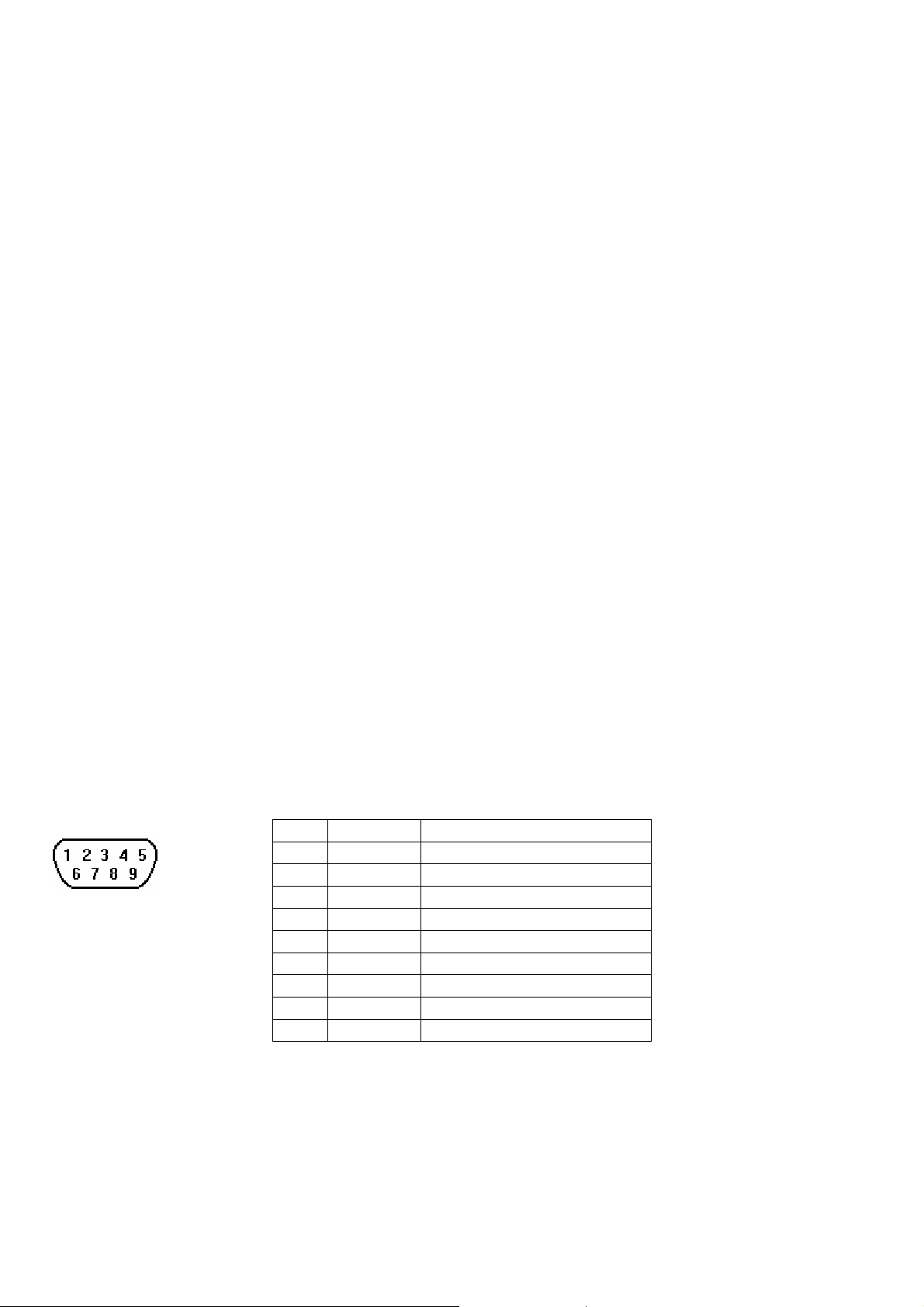
Pin assignment of the 9 Pin, Male, SUB-D, COM1 [RS-232] Port.
Pin# Symbol Function
1 DCD Data Carrier Detect
COM1 [RS-232]
2 RxD Received Data
3 TxD Transmitted Data
4 DTR Data Terminal Ready
5 GND Signal Ground
6 DSR Data Set Ready
7 RTS Ready to send output
8 CTS Clear to send input
9 RI Ring Indicator
4
Page 5
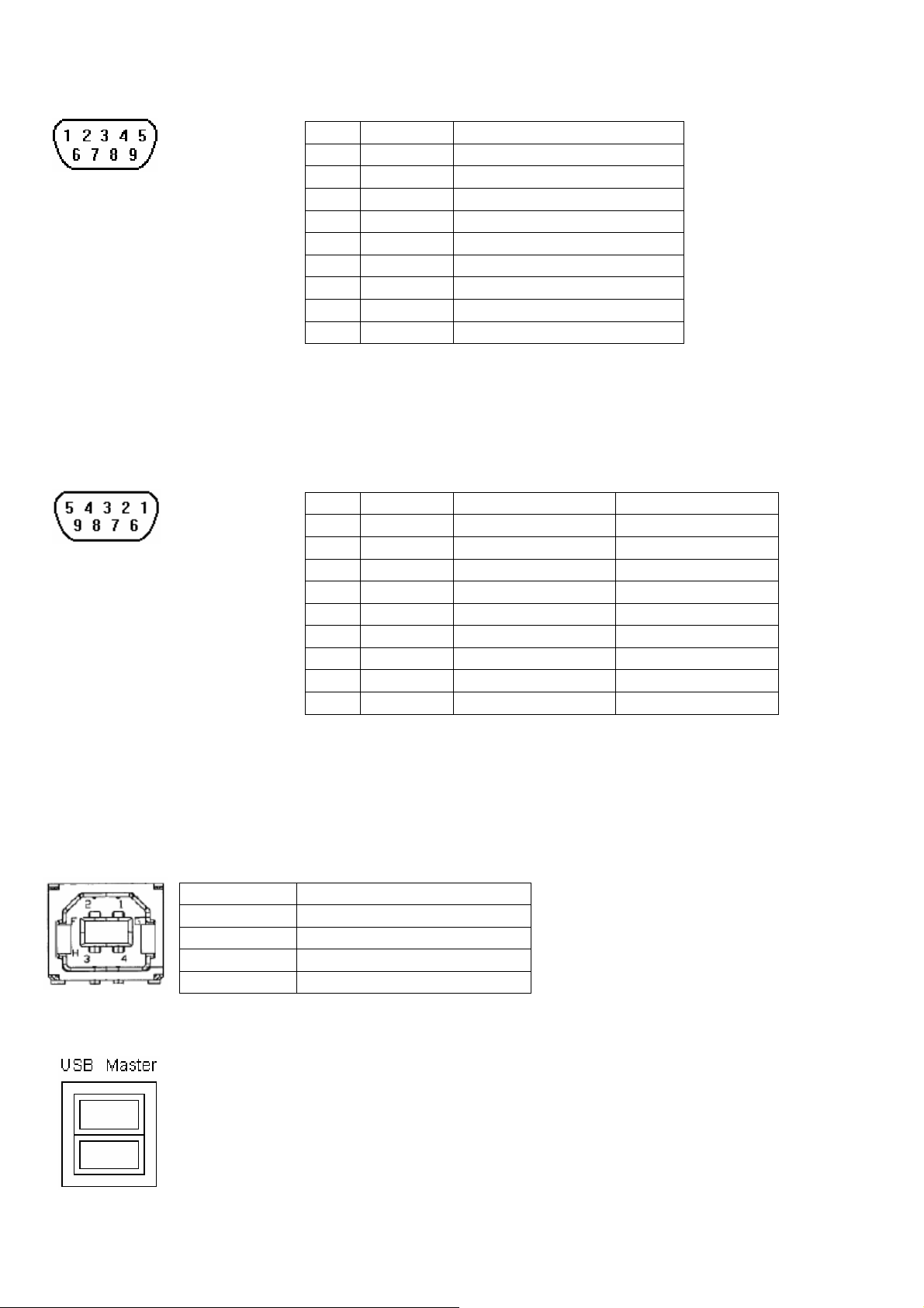
2.3.2 Connector COM2 [RS232]
Pin Designations
COM2 [RS-232]
Pin 1,6,8 short.
2.3.3 Connector COM3[RS485]
Pin Designations
COM3 [RS-485]
Pin assignment of the 9 Pin, Male, SUB-D COM2 [RS-232] Port
Pin# Symbol Function
1
2 RxD Received Data
3 TxD Transmitted Data
4
5 GND Signal Ground
6
7 RTS Ready to send output
8 CTS Clear to send input
9
Pin assignment of the 9 Pin, Female, SUB-D COM3 [RS-485] Port
Pin# Symbol RS-485 4wire RS-485 2wire
1
2 Tx+ Transmitted Data+ Data+
3 Tx- Transmitted Data- Data4 Rx+ Received Data+
5 Rx- Received Data-
6 GND Signal Ground Signal Ground
7
8
9
2.3.4 USB Client port
The USB client port for ActiveSync,use a USB client to USB host cable connects the USB client port on
MT606 and the USB host port on user’s host PC.
Pin Function
1 N/C
2 USB_DATA3 USB_DATA+
4 GND
2.3.5 USB Master port
The USB Master port can connect USB mouse and USB keyboard.
5
Page 6
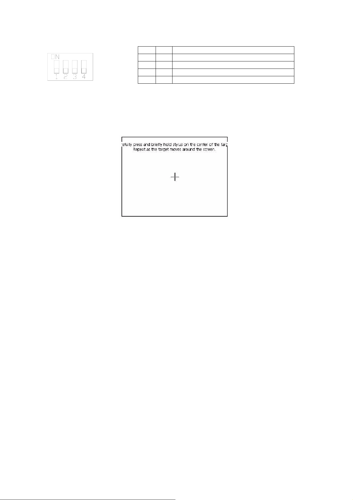
2.3.6 Dip Switch
SW1 SW2 Mode
ON OFF Touch Screen Calibrate mode
OFF ON Boot Loader mode
z Touch Screen Calibrate mode: In this mode when you power on the MT600, the screen will display a
“+” sign at the center of the screen. Use a stylus or finger to push the center of the “+” until it moves.
The “+” moves to upper-left, lower-left, lower-right and upper-right corners. When all five “+” are
done the “+” will disappear. The Touch Screen parameter will store at Flash Rom.
z Boot Loader mode: Load new Windows CE image file.
If the MT600 already load the CE image with boot loader. Set the DIP SW2 ON then power ON into
boot loader mode. Refer the load Win CE image document.
2.4 CE Requirements
EU directives that apply to the MT-600 Series:
z EMC Directive (89/336/EEC, 92/31/EEC, 93/68/EEC) electromagnetic emissions and immunity
z Machinery Directive (89/392/EEC, 91/368/EEC, 93/44/EEC, 93/ 68/EEC) machine safety
z MT500 products will be CE-marked to indicate compliance with the EMC Directive.
The MT-600 Series has been designed to operate satisfactorily in electromagnetic noise (immunity) and
without emitting high levels of electrical noise into the environment (emission). The units are designed to
meet European Community standards when installed per the wiring instructions in this manual.
Compatibility
Standards
The MT-600 has been designed to meet electromagnetic compatibility for industrial
environments.
• CISPR (EN 55011) Group 1, Class A Radiated Emissions levels
• EN50081-2 Generic emission standard, industrial environment (Also US FCC
Class A)
• EN50082-2 Generic immunity standard, industrial environment
6
Page 7
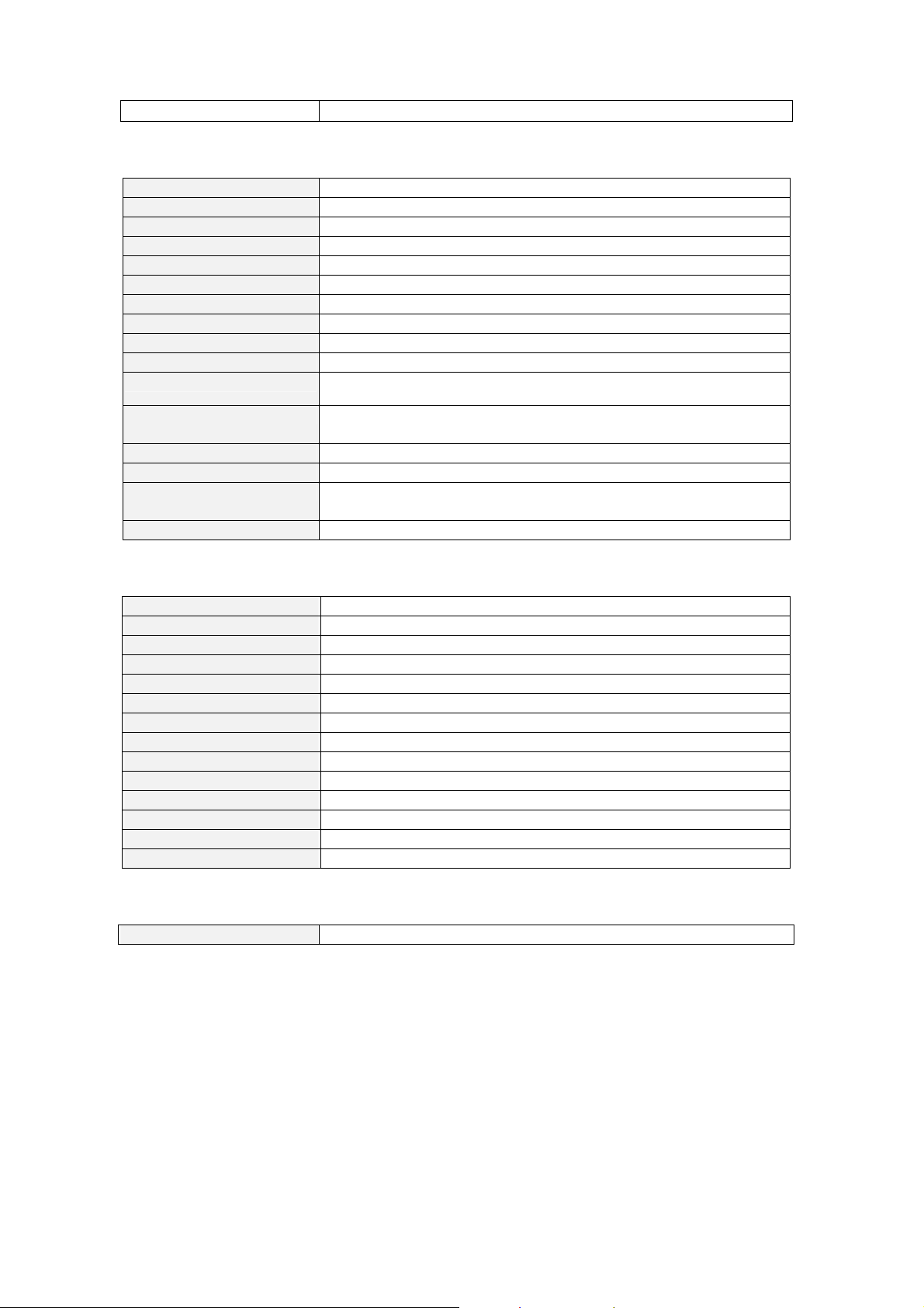
3.0 Specifications
MT608S
Display 7.7" DSTN
Brightness 150 cd/m2
Color 4096 colors
Contrast Ratio 30:1
Resolution (WxH dots) 640 x 480
Back light CCFLx2
CCFL life time 25,000 hr. min.
Touch panel 4 wires resistive type
Touch Accuracy 2mm
Surface Hardness
I/O port
Audio 1 x Audio jack for external headphone
Processor Intel® PXA255 200MHz
DRAM
Storage 32MB Flash memory on board,
RTC Ye s
Hardware Specification
4H
COM1 [RS-232], COM2 [RS232], COM3 [RS485]
1 Ethernet port (10/100Base-T)
1 x Audio jack for external Microphone
64MB
1 CompactFlash card slot
General Specification
Input Power 21-25 VDC
Power Consumption 350 mA@24VDC
CE Complies with EN50081-2 and EN50082-2 standards
FCC Complies with FCC Class A
Voltage resistance 500VAC (1 min.)
Isolation resistance Exceed 50MΩ at 500VDC
Vibration endurance 10 to 25 Hz (X,Y,Z direction 2G 30minutes)
Protection structure IP65 front panel (O ring seal)
Operating Temperature 0~45°C
Operation humidity 10-90% RH (non –condense)
Enclosure Plastic PBT + PC
Dimensions HxWxD 231 x 176 x 55mm
Panel cutout dimension 222 x 167 mm
Weight Approx. 1.3 kg
Operating System
Operating System Windows CE.net 4.1
7
Page 8

4.0 Dimensions of MT-608S
R
B
d
Front View
Side View
ottom View
f
c b g
e
a. CompactFlash slot g. USB client
b. Sound ports h. USB Master
c. MIC ports i. Com1[RS232]
d. Ethernet port (RJ-45) j. Com2[RS232]
e. Fuse k. Com3[RS485]
f. Power connector
i j k
ear View
a
Cutout dimensions:
MT-608S:
h
222mm(8.74”) W x 167mm(6.57”) H
8
 Loading...