

Page 1

User Manual
iR- COP
This guide walks through important information for iR-COP
V1.01
Page 2

Table of Contents
1 Product Overview ................................................................................................... 1
2 Specifications .......................................................................................................... 2
3 LED Insicators .......................................................................................................... 3
3.1 L.V LED ............................................................................................................ 3
3.2 IO RUN/ERR LED ............................................................................................. 3
3.3 CAN-RUN LED ................................................................................................. 3
3.4 CAN-ERR LED .................................................................................................. 3
4 Configuration .......................................................................................................... 4
4.1 Node Setting .................................................................................................. 4
4.2 Baud Rate Setting (DIP Switch) ...................................................................... 4
4.3 CAN Bus Connect ........................................................................................... 4
4.4 CANopen Features ......................................................................................... 4
5 Communication Error Control ................................................................................ 5
5.1 Introduction ................................................................................................... 5
5.2 Node Guarding Protocol ................................................................................ 5
5.3 Heartbeat Protocol ......................................................................................... 6
5.4 Error Behavior ................................................................................................ 7
6 Object Dictionary .................................................................................................... 8
6.1 Communication Profile Area .......................................................................... 8
6.1.1 1000h: Device Type ....................................................................... 9
6.1.2 1001h: Error Register .................................................................. 10
6.1.3 1002h: Manufacturer Status Register ......................................... 10
6.1.4 1003h: Predefined Error Field ..................................................... 11
6.1.5 1005h: SYNC COB-ID Message ..................................................... 13
6.1.6 1008h: Manufacturer Device Name............................................. 13
6.1.7 1009h: Manufacturer Hardware Version ..................................... 13
6.1.8 100Ah: Manufacturer Software Version ...................................... 13
6.1.9 100Ch: Guard Time & 100Dh: Life Time Factor ........................... 13
6.1.10 1010h: Store Parameters ............................................................. 13
6.1.11 1011h: Restore Default Parameters ............................................. 13
6.1.12 1014h: COB-ID EMCY ................................................................... 19
6.1.13 1015h: Inhibit Time EMCY............................................................ 19
6.1.14 1016h: Consumer Heartbeat Time .............................................. 19
6.1.15 1017h: Producer Heartbeat Time ................................................ 19
6.1.16 1029h: Error Behavior Object ...................................................... 19
6.2 PDO Communication Parameter .................................................................. 20
6.2.1 RxPDO Communication Parameter .............................................. 20
Page 3

6.2.2 TxPDO Communication Parameter .............................................. 21
6.2.3 PDO Mapping Parameter ............................................................. 23
6.2.4 Mapping Parameter ..................................................................... 27
6.3 I/O Device Object Dictionay ......................................................................... 27
6.3.1 Read digital input ......................................................................... 27
6.3.2 Write digital output ...................................................................... 29
6.3.3 Read Analog input ........................................................................ 30
6.3.4 Write Analog output .................................................................... 30
6.4 Manufacturer-specific profile area .............................................................. 30
6.4.1 2000h~2001h: Digital input filter ................................................. 30
6.4.2 3000h~300Fh: Module Registers ................................................. 30
6.4.3 4000h~4007h: iBus and Module Information .............................. 31
7 Power Consumption ............................................................................................. 32
8 Connecting Remote I/O using CODESYS ............................................................... 33
Page 4
iR-COP
1
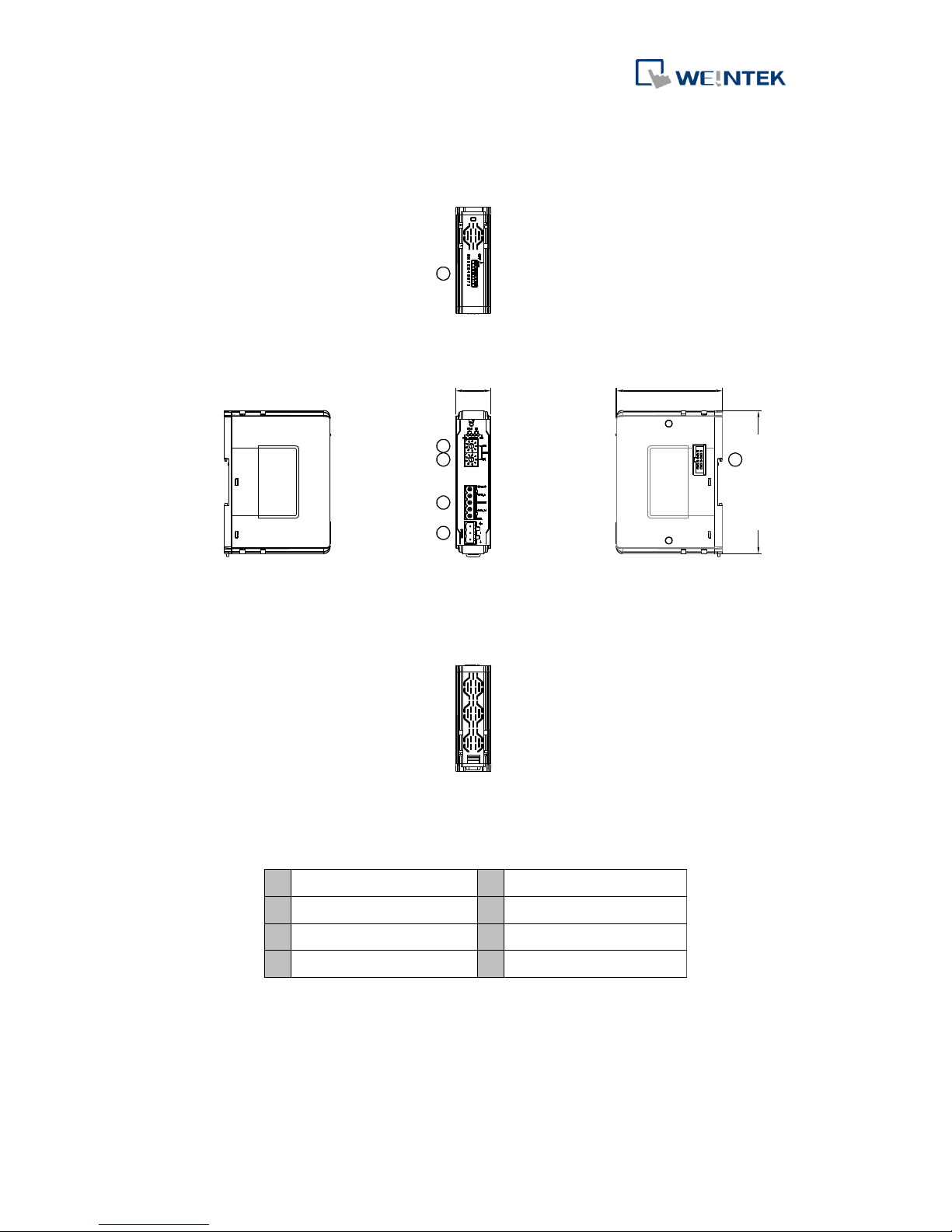
1 Product Overview
a
Node ID rotary switch x10
e
Baud Rate DIP Switch
b
Node ID rotary switch x1
f
Expansion Connector
c
CAN bus Connector
d
Power Connector
英文版 簡中版 日文版
Front View
Side ViewSide View
Top View
Bottom View
a
b
c
d
e
f
a
b
c
d
e
81mm [3.19"]
109mm [4.29"]
Page 5
iR-COP
2
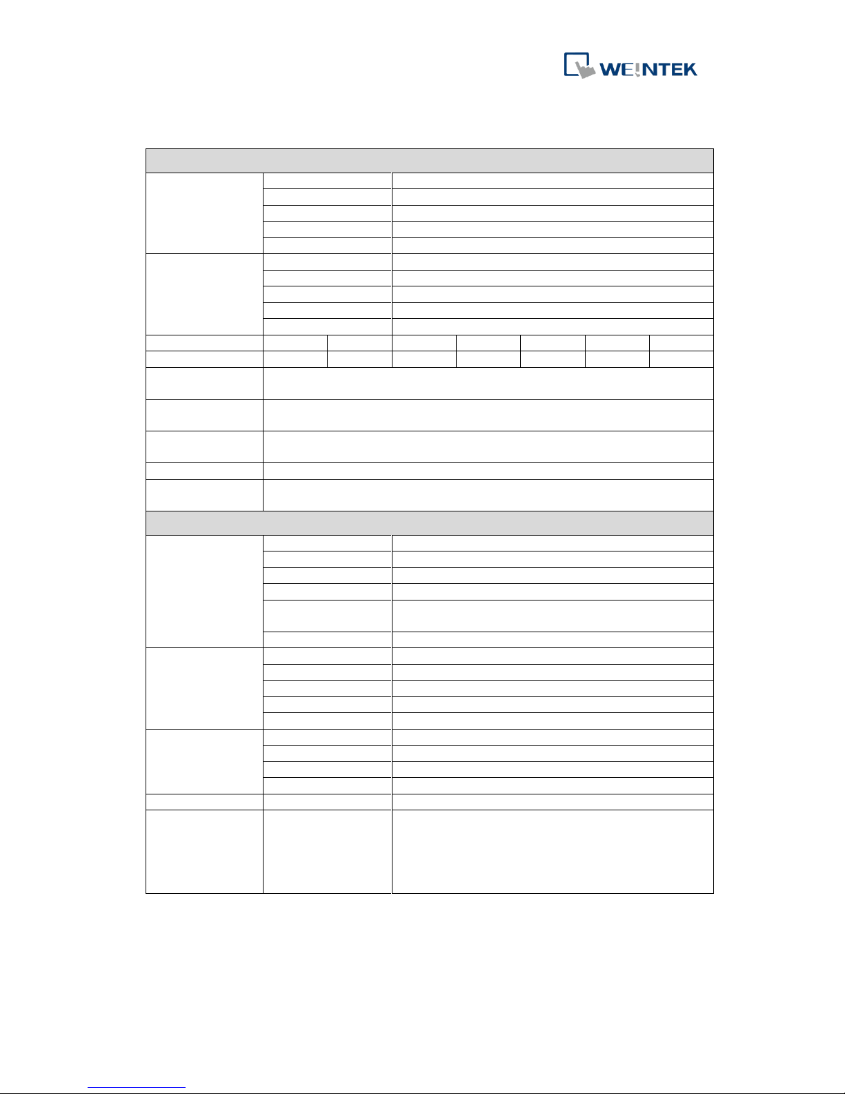
2 Specifications
Communication Interface Specifications
Expansion I/O
Module
No. of Bus Terminals
Depends on Power Consumption
Digital Input Point
Max. 256
Digital Output Point
Max. 128
Analog Input Channel
Max. 64
Analog Output Channel
Max. 64
Indicators
CAN RUN (Green)
CANopen Status Indicator
CAN ERR (Red)
CANopan Error Indicator
L.V (Red )
Low Voltage Status Indicator
IO RUN (Green)
Module Status Indicator
IO ERR (Red)
Module Error Indicator
Data Transfer Rate
1M
800k
500k
250k
125k
100k
50k
Length of the Cable
20m
50m
100m
250m
500m
600m
1,000m
Number of PDOs
(CANopen)
8 Transmit PDOs / 8 Receive PDOs
Process Data
Operating Modes
synchronous, event-driven ,event timer, polling
Number of SDOs
Available
1 Standard SDOs
Bus Connection
1 x open style connector, 5-pole, plug included
Additional CANopen
Features
life/node guarding, heartbeat, emergency object, variables mapping, store/restore, output
error mode.
General Specification
Power
Power Supply
24 VDC (-15%/+20%)
Power Dissipation
Nominal 24VDC@ 100mA
Current for Internal Bus
Max 2A @ 5VDC
Current Consumption
170mA @ 5VDC
Electrical Isolation
Isolated CANopen : Yes
Isolated power : Yes
Back-up Fuse
≤ 1.6A Self-recovery
Specification
PCB Coating
Yes
Enclosure
Plastic
Dimensions WxHxD
27 x 109 x 81 mm
Weight
Approx. 0.15 kg
Mount
35mm DIN rail mounting
Environment
Protection Structure
IP20
Storage Temperature
-20° ~ 70°C (-4° ~ 158°F)
Operating Temperature
0° ~ 55°C (32° ~ 131°F)
Relative Humidity
10% ~ 90% (non-condensing)
Connection
Cross-section
0.5 mm² ... 2.5 mm², stranded, solid wire, AWG 26-12
Certification
EMC Immunity
Conforms to
EN 55032: 2012+AC: 2013, Class A
EN 61000-6-4: 2007+A1:2011
EN 55024: 2010+A1: 2015
EN 61000-6-2:2005
Page 6
iR-COP
3
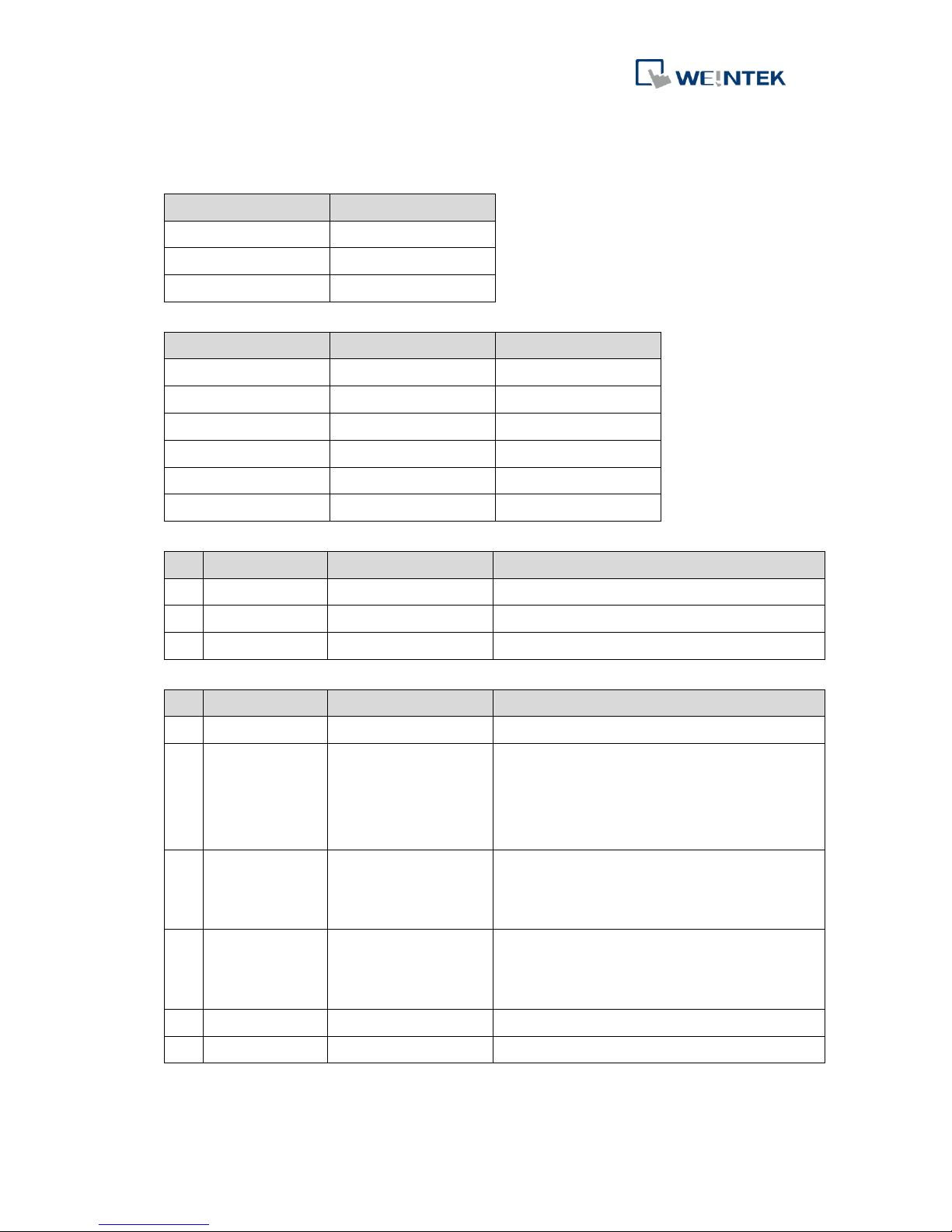
3 LED Insicators
3.1 L.V LED
L.V LED state
Description
OFF
24V power normal
Blinking
Detect 24V power
ON
24V power error
3.2 IO RUN/ERR LED
RUN LED
ERR LED
Description
OFF
OFF
Power off or no power
Blinking
OFF
IO initiating
Blinking
ON
IO initiation error
ON
OFF
IO working
ON
Blinking
IO module alarm
ON
ON
IO communication fault
3.3 CAN-RUN LED
NO
CAN-RUN LED
State
Description
1
ON
OPERATIONAL
The device is in the OPERATIONAL state.
2
Blinking
PRE_OPERATIONAL
The device is in the PRE_OPERATIONAL state.
3
Single flash
STOPPED
The device is in the STOPPED state.
3.4 CAN-ERR LED
NO
CAN-ERR LED
State
Description
1
ON
CAN Bus off
The CAN Bus controller is off.
2
Triple flash
SYNC error
The SYNC message has not been received
within the configured communication cycle
period time out (see Object Dictionary Entry
1006h).
3
Double flash
Error control event
A guard event (NMT-Slave or NMT-master) or a
heartbeat event (Heartbeat consumer) has
Occurred.
4
Single flash
Warning limit reached
At least one of the error counters of the CAN Bus
controller has reached or exceeded the warning
level (too many error frames).
5
Blinking
Invalid configuration
General configuration error.
6
OFF
No error
The Device is in working condition.
Page 7
iR-COP
4
4 Configuration
4.1 Node Setting
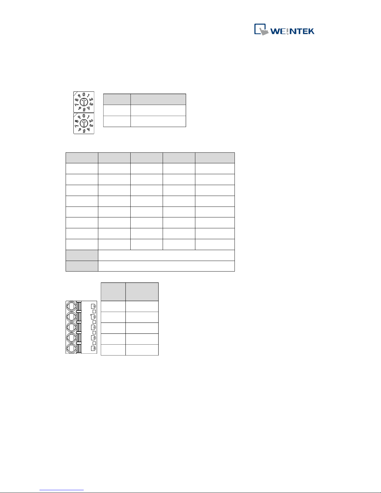
The node ID is set by Rotary Switches, range from 1 to 99 (0 is not allowed).
4.2 Baud Rate Setting (DIP Switch)
SW4
SW3
SW2
SW1
Baud Rate
0 0 0 0 Auto rate
0 0 0 1 1Mbps
0 0 1 0 800Kbps
0 0 1 1 500Kbps
0 1 0 0 250Kbps
0 1 0 1 125Kbps
0 1 1 0 100Kbps
0 1 1 1 50Kbps
SW5-7
Reserved
SW8
CAN Bus 120Ω Terminator
4.3 CAN Bus Connect
4.4 CANopen Features
8 TxPDO
8 RxPDO
Standard SDO
Emergency object
Synchronization object (SYNC, without time stamp)
Guarding
Heartbeat (Producer/ Consumer)
NMT objects
Setting
Description
0
Invalid Node ID
1~99
Valid Node ID
PIN#
Name
1
CAN_G
2
CAN_L
3
SHIELD
4
CAN_H
5
N/A
Page 8
iR-COP
5
5 Communication Error Control
5.1 Introduction
Node Guarding protocol and Heartbeat protocol can be used to detect device failures
on a CANopen network, please use one of these two protocols at a time.
5.2 Node Guarding Protocol
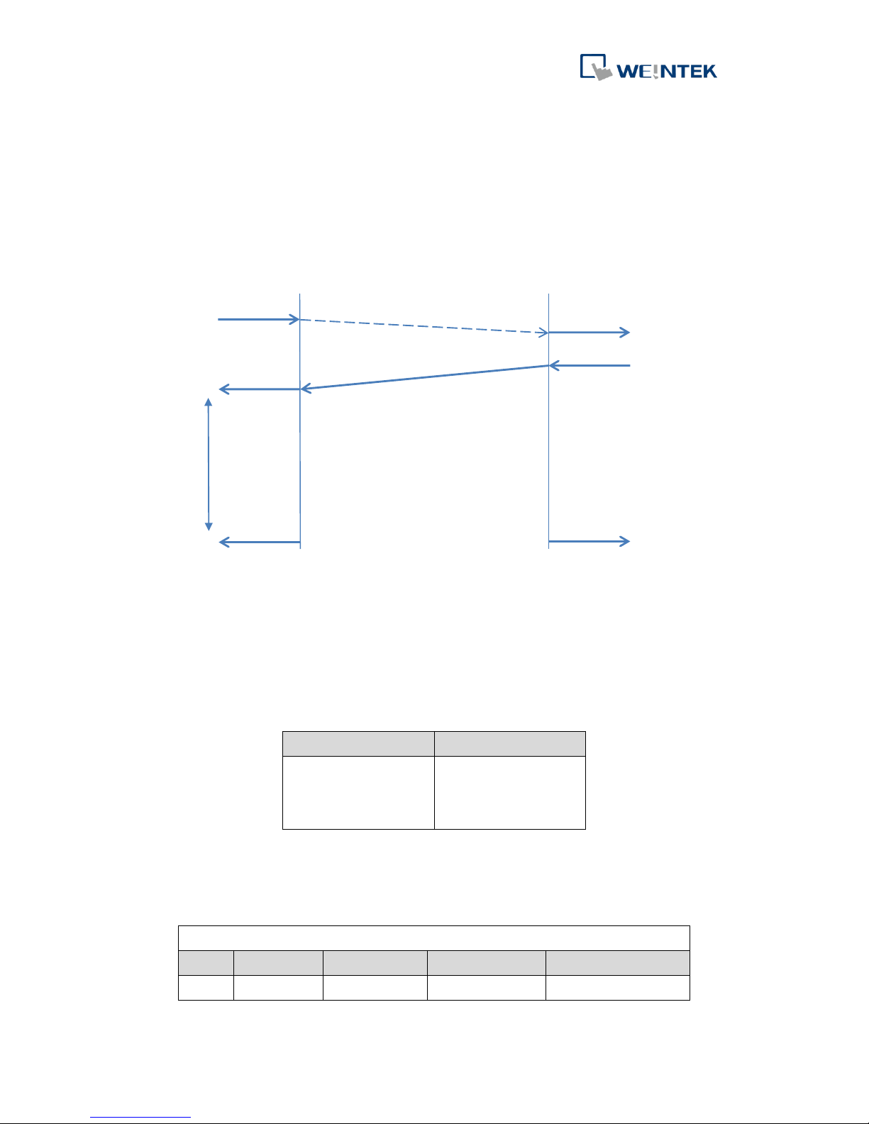
With Node Guarding, a certain network node (NMT-master) sends a remote transmit
request to the other nodes (NMT-slave) in the network one after the other (polling)
at defined intervals (Node Guard Time). The NMT-slaves respond to the request by
transmitting a data telegram with its current communication state: Pre-operation,
Operation, Stopped, within a certain time (Node Life Time). The format of the
telegram is as below:
Bit7
Bit6~Bit0
Toggle bit.
4: Stopped
5: Operational
127: Pre-operational
Node Life Time is calculated by multiplying two parameters: Guard Time and Life
Time Factor.
Node Life Time = Life Time Factor x Guard Time (ms)
Guard Time
Index
Sub Index
Data Type
Default Value
Description
100Ch
00h
UNSIGNED16
0000h
0:Disable
Master
Slave
Remote request
indication
response
request
confirmation
Node guarding time
indication
indication
Guarding event
CAN-ID = 1792 + Node-ID
Page 9
iR-COP
6
Life Time Factor
Index
Sub Index
Data Type
Default Value
Description
100Dh
00h
UNSIGNED8
00h
0:Disable
The NMT-slaves also monitor whether they have received a request from the
NMT-master within “Node Life Time”. If the request was absent for longer than the
life time, the NMT-slaves assume that the NMT-master has failed and indicates this
as a “Life Guard Event” to the host controller.
5.3 Heartbeat Protocol
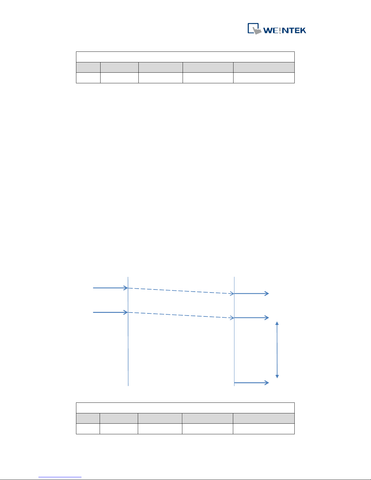
Heartbeat protocol is an error control service that does not require remote frames.
According to the heartbeat principle, a Heartbeat Producer automatically transmits
its communication state at regular intervals to the Heartbeat Consumers, as an
evidence of its communication ability. The Heartbeat Consumer Time describes the
maximum time within which the arrival of a heartbeat message is expected by a
Heartbeat Consumer. Absence of the heartbeat message for longer than Heartbeat
Consumer Time will be indicated by the Heartbeat Consumer as a Heartbeat Event to
the host controller.
Producer Heartbeat Time
Index
Sub Index
Data Type
Default Value
Description
1017h
00h
UNSIGNED16
00h
0:Disable (unit:ms)
Master
Slave
Remote request
indication
request
Heartbeat time
indication
Heartbeat
CAN-ID = 1792 + Node-ID
request
indicatio
Page 10
iR-COP
7
Consumer Heartbeat Time
Index
Sub Index
Data Type
Default Value
Description
1016h
00h
UNSIGNED32
00h
---
Bit31-24
Bit23-16
Bit15-0
Reserved(00h)
Node-ID
Heartbeat Time
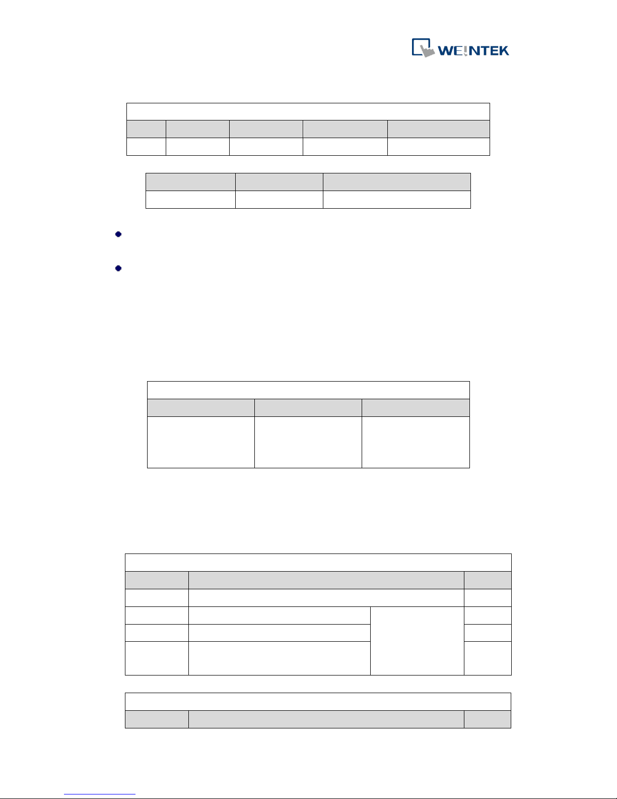
Node ID: The heartbeat mechanism is disabled when the ID is 0 or larger than
127.
Heartbeat time unit: ms
Please note that Consumer Heartbeat Time should be longer than Producer
Heartbeat time.
5.4 Error Behavior
When a Life Guarding Event or Heartbeat Event occurs:
The state can be configured via the object dictionary entry (Error Behavior Object).
Error Behavior Object
Index
Sub Index
Description
1029h
01h
0 :pre-operation
1 :no state change
2 :stopped
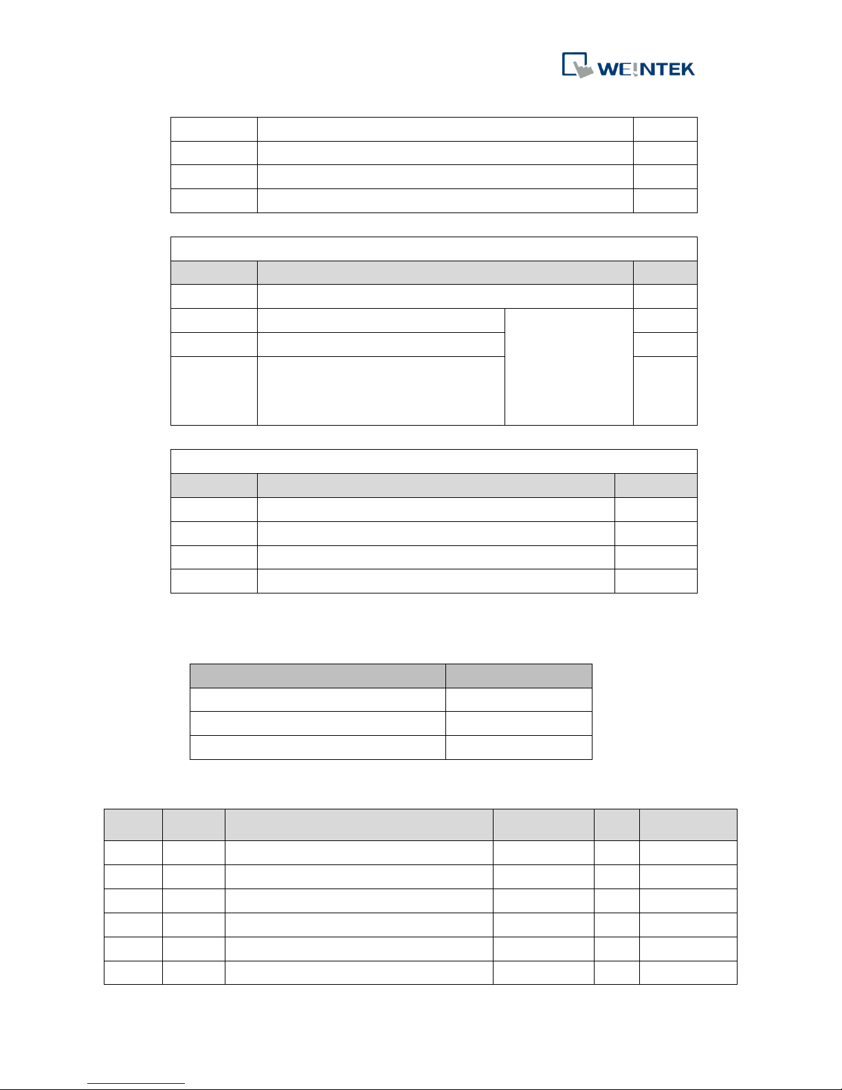
Digital / Analog Output can be configured via error mode and error output value.
If Error Mode is enabled when an event occurs, the output value will be given in
Error Value.
If Error Mode is disabled when an event occurs, the output value remains the same.
Index 6206:Error mode digital output (8-bit)
Sub Index
Description
Default
00h
Highest sub-index supported
01h
Error mode output 01h to 08h
0:output value
remains same
1:output value is
given in 6207h
FFh
02h
Error mode output 09h to 10h
FFh
03h-FEh
Error mode output 11h to 7F0h
FFh
Index 6207:Error value digital output (8-bit)
Sub Index
Description
Default
Page 11
iR-COP
8
00h
Highest sub-index supported
01h
Error Value output 01h to 08h
00h
02h
Error Value output 09h to 10h
00h
03h-FEh
Error Value output 11h to 7F0h
00h
Index 6443:Analog output error mode
Sub Index
Description
Default
00h
Highest sub-index supported
01h
Error mode analog output 01h
0:actual value
rest
1:output value is
given in 6444h
others = reserved
01h
02h
Error mode analog output 02h
01h
03-FEh
Error mode analog output 03-FEh
01h
Index 6444:Analog output error value integer
Sub Index
Description
Default
00h
Highest sub-index supported
01h
Analog output 01h
0000 000h
02h
Analog output 01h
0000 000h
03-FEh
Analog output 03h-FEh
0000 000h
6 Object Dictionary
Object Area
Index range (hex)
Communication Profile Area
1000-1FFF
Manufacturer Specific Profile Area
2000-5FFF
Standardized Device Profile Area
6000-9FFF
6.1 Communication Profile Area
Index
Sub
Index
Description
Type
ro/
rw
Default
1000h
00h
Device type
UNSIGNED32
ro
---
1001h
00h
Error register
UNSIGNED8
ro 0 1002h
00h
Manufacturer status register
UNSIGNED32
ro 0
01h
Module alarm code
UNSIGNED32
ro
0
02h
Module disconnected code
UNSIGNED32
ro
0
03h
iBus initialization error code
UNSIGNED32
ro
0
Page 12
iR-COP
9
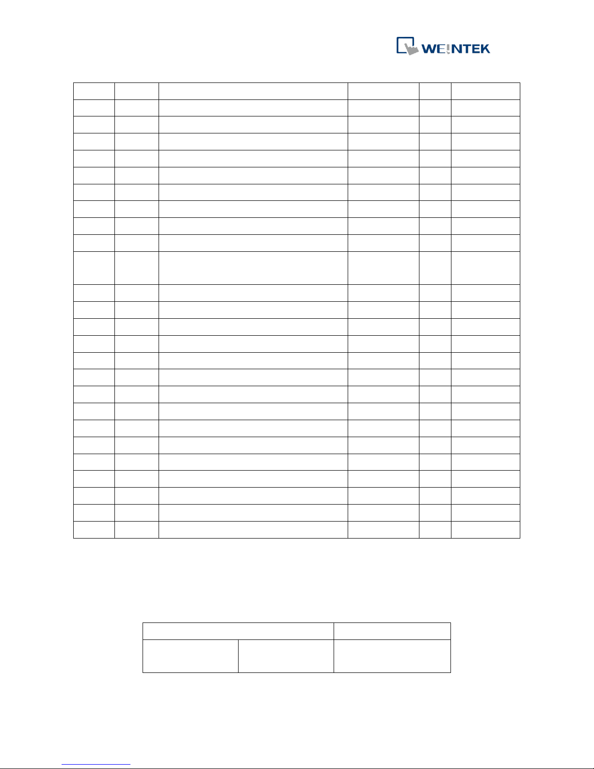
1003h
00h
Error code (no. of sub-index)
UNSIGNED32
rw 0
01h
Emergency error code (newest)
UNSIGNED32
ro 0
02-3Fh
Emergency error code
UNSIGNED32
ro 0
40h
Emergency error code (latest)
UNSIGNED32
ro 0 1005h
00h
SYNC COB-ID message
UNSIGNED32
ro
00000080h
1008h
00h
Manufacturer device name
STRING
ro
‘iR-COP’
1009h
00h
Manufacturer hardware version
STRING
ro
‘1.00.0’
100Ah
00h
Manufacturer software version
STRING
ro
‘1.00.0’
100Ch
00h
Guard time
UNSIGNED16
rw 0 100Dh
00h
Life time factor
UNSIGNED8
rw
0
1014h
00h
COB-ID EMCY
UNSIGNED32
rw
80h +
Node-ID
1015h
00h
Inhibit time EMCY
UNSIGNED16
rw 0 1016h
00h
Number of sub-index
UNSIGNED8
ro 0
01h
Consumer heartbeat time
UNSIGNED32
rw 0 1017h
00h
Producer heartbeat time
UNSIGNED16
rw 0 1018h
Identity object
00h
Number of sub-index
UNSIGNED8
ro
04h 01h
Vendor-ID
UNSIGNED32
ro
0000044Eh
02h
Product code
UNSIGNED32
ro
00000701h
03h
Revision number
UNSIGNED32
ro
--- 04h
Serial number
UNSIGNED32
ro
---
1027h
00h
Number of connected modules
UNSIGNED8
ro
01h – 10h
01-10h
Module 1-16 of Device code
UNSIGNED16
ro
----
1029h
Error behavior object
00h
Number of sub-index
UNSIGNED8
ro
01h 01h
Communication error
UNSIGNED8
rw
0
6.1.1 1000h: Device Type
MSB
31 24
23 16
LSB
15 0
Additional information
General information
Specific
functionality
I/O functionality
Device profile number
Page 13
iR-COP
10
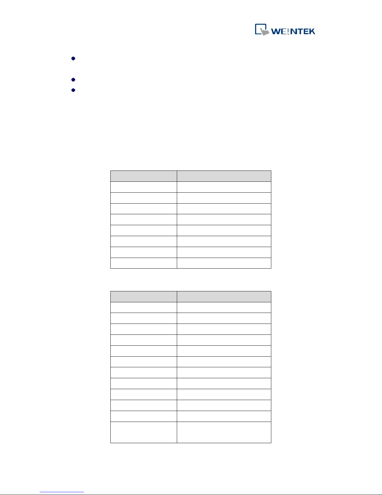
Specific functionality: Remains 0 since iR-COP model does not have specific
functionality.
General information: 191h according to document DS-401
I/O functionality:
When bit 16 is 1: Digital input channel exists.
When bit 17 is 1: Digital output channel exists.
When bit 18 is 1: Analog input channel exists.
When bit 19 is 1: Analog output channel exists.
Bit 20 to 23 reserved: Value is 1.
6.1.2 1001h: Error Register
Please find 1003h for more information on error registers.
Bit
Meaning
0
Generic error
1
Current error
2
Voltage error
3
Temperature error
4
Communication error
5
Pertains to the device profile
6
Reserved(0)
7
Manufacturer specific
6.1.3 1002h: Manufacturer Status Register
Bit
Description
0
Low power alarm
1
Hardware error
2
Reserved
3
Heartbeat event
4
Guard event
5
CAN in error passive mode
6
CAN overrun
7
Module lost connection
8
Module alarm
9
iBus initialization fault
10
Number of iBus exceeds 16
11
Power consumption exceeded
at iBus system
Page 14
iR-COP
11
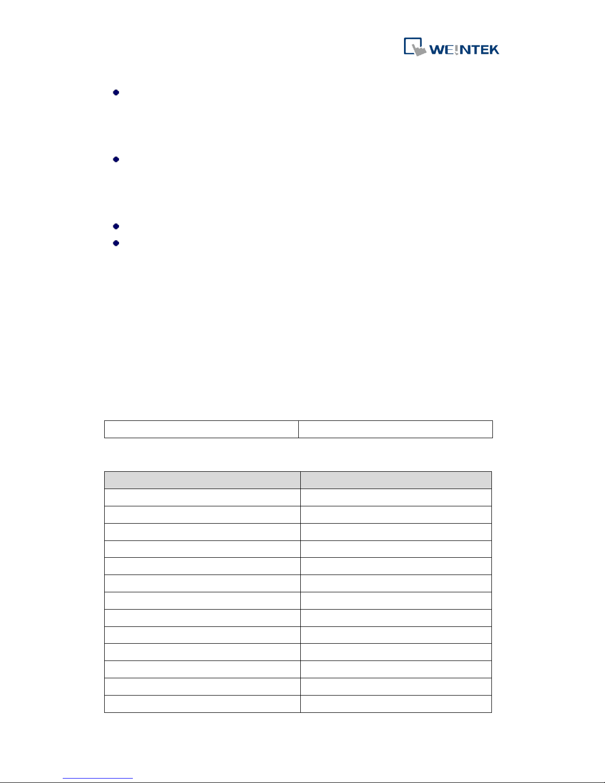
Sub Index 01: Module alarm
Bit0 is 1 means that the alarm is triggered by the first module,
and Bit2 is 1 means that the alarm is triggered by the second
module, and so on.
Sub Index 02: Module lost connection
Bit0 is 1 means that the first module has lost its connection, and
Bit2 is 1 means that the second module has lost its connection,
and so on.
Sub Index 03: iBus initialization error
Sub Index 01: Error bit (Error Code)
6.1.4 1003h: Predefined Error Field
When an error occurs, Emergency Object will be generated and recorded in
Predefined Error Field, providing an Error History.
Sub Index 01 and more: Number of error records
Setting index 0 to 0 will erase the field, and index 0 can only be set to 0.
Setting index 0 to values other than 0 will make SDO reply abort 0609 and 0030h.
Bit0~15 describe Error Code while Bit16~31 provide additional information.
Byte:
MSB
LSB
Additional information
Error code
Emergency Error Codes:
Error Code (hex)
Meaning
00xx
Error Reset or No Error
10xx
Generic Error
20xx
Current
21xx
Current, device input side
22xx
Current inside the device
23xx
Current, device output side
30xx
Voltage
31xx
Mains Voltage
32xx
Voltage inside the device
33xx
Output Voltage
40xx
Temperature
41xx
Ambient Temperature
42xx
Device Temperature
Page 15
iR-COP
12
50xx
Device Hardware
60xx
Device Software
61xx
Internal Software
62xx
User Software
63xx
Data Set
70xx
Additional Modules
80xx
Monitoring
81xx
Communication
8110
CAN Overrun (Objects lost)
8120
CAN in Error Passive Mode
8130
Life Guard Error or Heartbeat Error
8140
Recovered from bus off
8150
Transmit COB-ID collision
82xx
Protocol Error
8210
PDO not processed due to length
error
8220
PDO length exceeded
90xx
External Error
F0xx
Additional Functions
FFxx
Device Specific
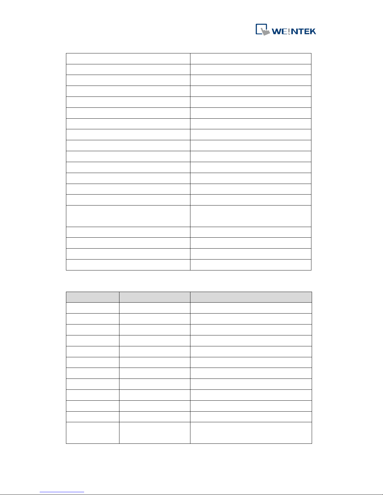
iR-COP Error Registers:
Error Register
Predefined Error Field
Description
01h
3100h
Low power alarm
01h
5000h
Hardware error
10h
8100h
CAN Bus off (Reserved)
10h
8130h
Heartbeat event
10h
8130h
Guard event
10h
8120h
CAN in error passive mode
10h
8110h
CAN overrun
80h
7000h
Module lost connection
80h
7001h
Module alarm
80h
7002h
iBus initialization fault
80h
7003h
Number of iBus exceeds 16
80h
7004h
Power consumption exceeded at iBus
system
Page 16
iR-COP
13
6.1.5 1005h: SYNC COB-ID Message
The COB-ID used for the SUNC message.
Bit0~10: SYNC COB-ID
Bit11~31: iR-COP is 0
6.1.6 1008h: Manufacturer Device Name
Contains the device name as a string: iR-COP
6.1.7 1009h: Manufacturer Hardware Version
Contains the device hardware version as a string: 1.00.0
6.1.8 100Ah: Manufacturer Software Version
Contains the device software version as a string: 1.00.0
6.1.9 100Ch: Guard Time & 100Dh: Life Time Factor
Guard Time and Life Time Factor are used in Node Guarding Protocol.
Setting 100C to 0 will disable guarding function.
Life Time = Life Time Factor * Guard Time (ms)
(Please find more details in Node Guarding Protocol in this manual.)
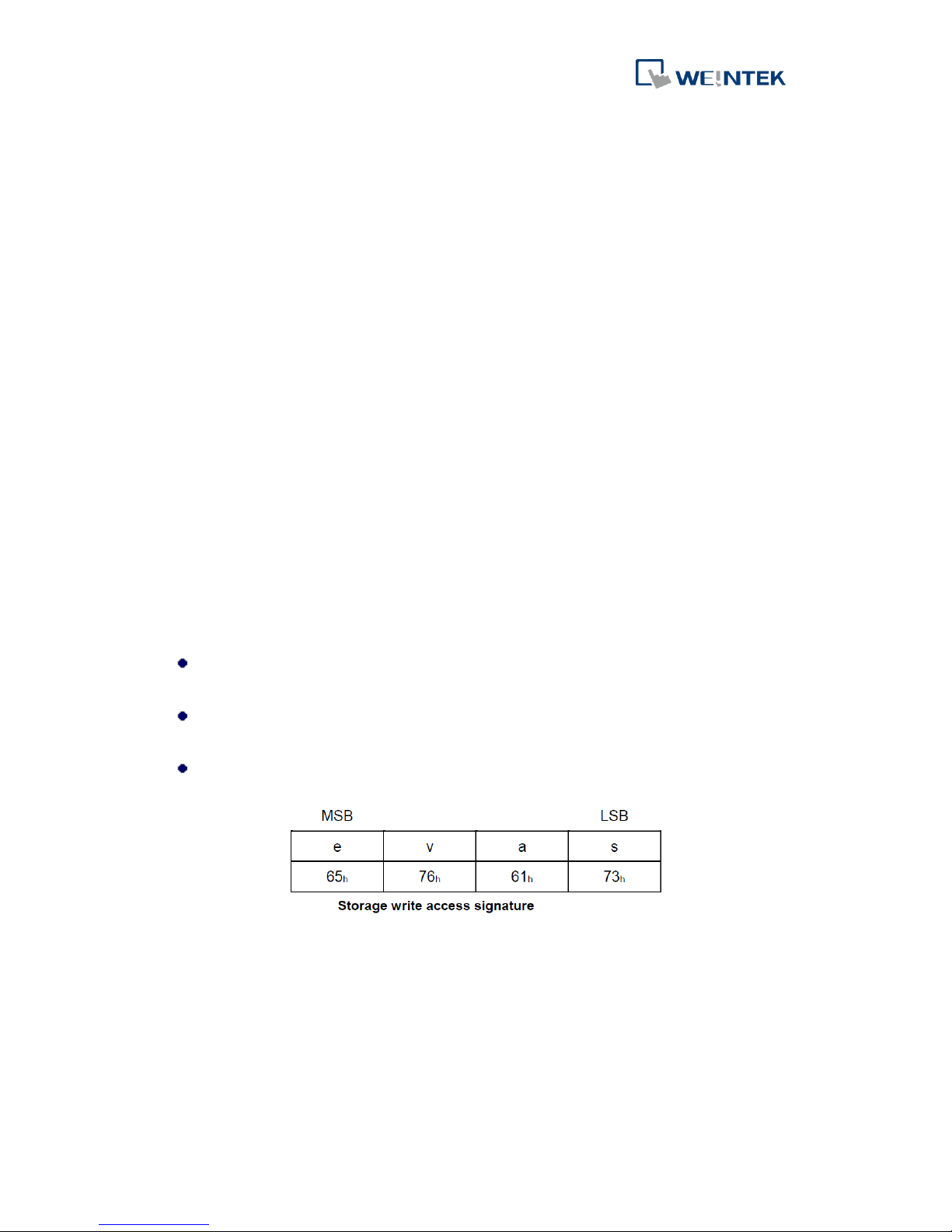
6.1.10 1010h: Store Parameters
This object shall control the saving of parameters in non-volatile memory.
VALUE DEFINITION
Sub Index 01h: refers to all parameters that may be stored on the CANopen
device.
Sub Index 02h: refers to communication related parameters (index from 1000
h
to 1FFFh).
Sub Index 03h refers to application related parameters (index from 6000
h
to
9FFFh).
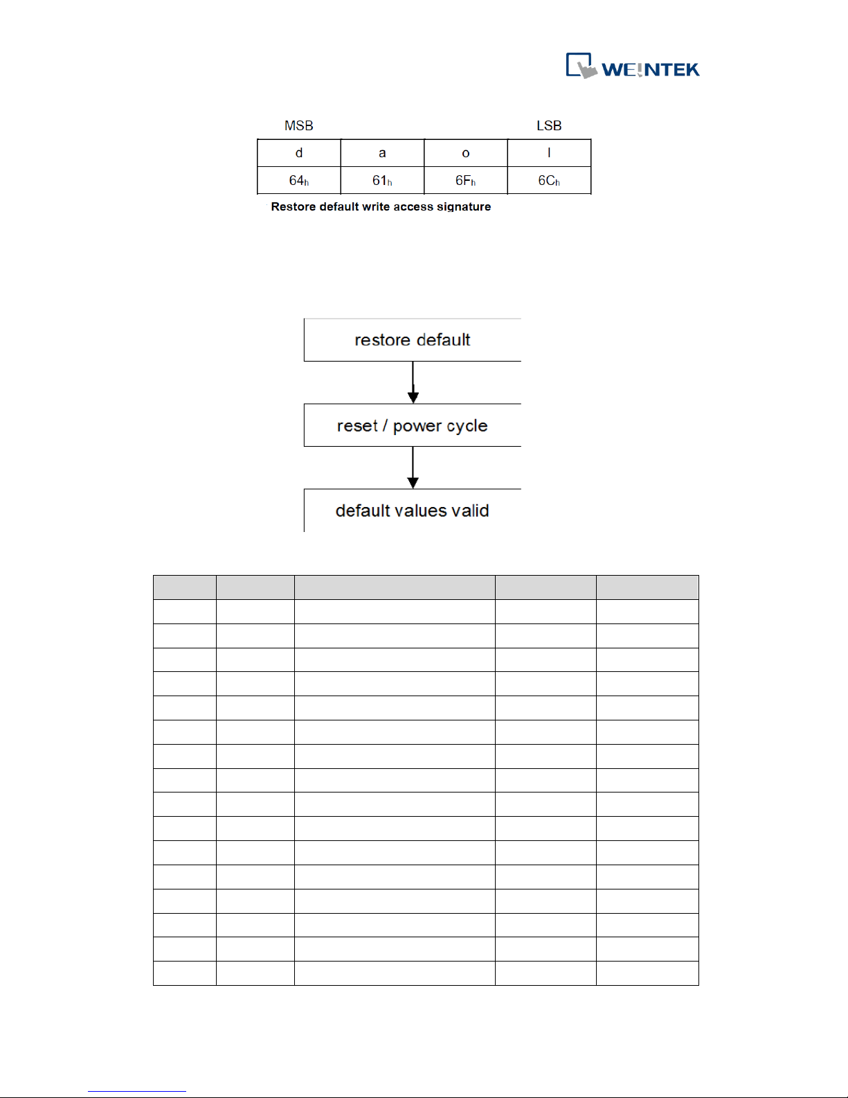
6.1.11 1011h: Restore Default Parameters
With this object the default values of parameters according to the communication
profile, device profile, and application profile are restored.
Sub Index 01h: refers to all parameters that may be restored
Sub Index 02h: refers to communication related parameters (Index from 1000h to
1FFFh).
Sub Index 03h: refers to application related parameters (Index from 6000h to 9FFFh).
Page 17
iR-COP
14
The default values shall be set valid after the CANopen device is reset (NMT service
reset node for sub-index from 01h to 7Fh, NMT service reset communication for
sub-index 02h) or power cycled.
Communication Parameters (1000h~1FFFh):
Index
Sub-index
Description
Type
Default
100Ch
00h
Guard time
UNSIGNED16
0
100Dh
00h
Life time factor
UNSIGNED8
0
1014h
00h
EMCY COB-ID
UNSIGNED32
80h + Node-ID
1015h
00h
EMCY inhibit time
UNSIGNED16
0
1016h
01h
Consumer heartbeat time
UNSIGNED32
0
1017h
00h
Producer heartbeat time
UNSIGNED16
0
1029h
01h
Communication error
UNSIGNED8
0
1400h
01h
COB-ID used by RPDO1
UNSIGNED32
200h + Node-ID
02h
Transmission type of RPDO1
UNSIGNED8
FFh
1401h
01h
COB-ID used by RPDO2
UNSIGNED32
300h + Node-ID
02h
Transmission type of RPDO2
UNSIGNED8
FFh
1402h
01h
COB-ID used by RPDO3
UNSIGNED32
400h + Node-ID
02h
Transmission type of RPDO3
UNSIGNED8
FFh
1403h
01h
COB-ID used by RPDO4
UNSIGNED32
500h + Node-ID
02h
Transmission type of RPDO4
UNSIGNED8
FFh
1404-
01h
COB-ID used by RPDO5-8
UNSIGNED32
8000000
Page 18
iR-COP
15
1407h
02h
Transmission type of RPDO5-8
UNSIGNED8
FFh
1800h
01h
COB-ID used by TPDO1
UNSIGNED32
180h + Node-ID
02h
Transmission type of TPDO1
UNSIGNED8
FFh 03h
Inhibit time of TPDO1
UNSIGNED16
0 05h
Event timer of TPDO1
UNSIGNED16
0
1801h
01h
COB-ID used by TPDO2
UNSIGNED32
280h + Node-ID
02h
Transmission type of TPDO2
UNSIGNED8
FFh 03h
Inhibit time of TPDO2
UNSIGNED16
0 05h
Event timer of TPDO2
UNSIGNED16
0
1802h
01h
COB-ID used by TPDO3
UNSIGNED32
380h + Node-ID
02h
Transmission type of TPDO3
UNSIGNED8
FFh 03h
Inhibit time of TPDO3
UNSIGNED16
0 05h
Event timer of TPDO3
UNSIGNED16
0
1803h
01h
COB-ID used by TPDO4
UNSIGNED32
480h + Node-ID
02h
Transmission type of TPDO4
UNSIGNED8
FFh 03h
Inhibit time of TPDO4
UNSIGNED16
0 05h
Event timer of TPDO4
UNSIGNED16
0
1804-7h
01h
COB-ID used by TPDO5-8
UNSIGNED32
280h + Node-ID
02h
Transmission type of TPDO5-8
UNSIGNED8
FFh 03h
Inhibit time of TPDO5-8
UNSIGNED16
0 05h
Event timer of TPDO5-8
UNSIGNED16
0
1600h
00h
Number of mapped application
objects in RPDO1
UNSIGNED8
08h
01h
1st application object
UNSIGNED32
6200 01 08h
02h
2st application object
UNSIGNED32
6200 02 08h
03h
3st application object
UNSIGNED32
6200 03 08h
04h
4st application object
UNSIGNED32
6200 04 08h
05h
5st application object
UNSIGNED32
6200 05 08h
06h
6st application object
UNSIGNED32
6200 06 08h
07h
7st application object
UNSIGNED32
6200 07 08h
08h
8st application object
UNSIGNED32
6200 08 08h
1601h
00h
Number of mapped application
objects in RPDO2
UNSIGNED8
04h
01h
1st application object
UNSIGNED32
6411 01 10h
02h
2st application object
UNSIGNED32
6411 02 10h
Page 19
iR-COP
16
03h
3st application object
UNSIGNED32
6411 03 10h
04h
4st application object
UNSIGNED32
6411 04 10h
1602h
00h
Number of mapped application
objects in RPDO3
UNSIGNED8
04h
01h
1st application object
UNSIGNED32
6411 05 10h
02h
2st application object
UNSIGNED32
6411 06 10h
03h
3st application object
UNSIGNED32
6411 07 10h
04h
4st application object
UNSIGNED32
6411 08 10h
1603h
00h
Number of mapped application
objects in RPDO4
UNSIGNED8
04h
01h
1st application object
UNSIGNED32
6411 09 10h
02h
2st application object
UNSIGNED32
6411 0A 10h
03h
3st application object
UNSIGNED32
6411 0B 10h
04h
4st application object
UNSIGNED32
6411 0C 10h
1604h
00h
Number of mapped application
objects in RPDO5
UNSIGNED8
08h
01h
1st application object
UNSIGNED32
6200 09 08h
02h
2st application object
UNSIGNED32
6200 0A 08h
03h
3st application object
UNSIGNED32
6200 0B 08h
04h
4st application object
UNSIGNED32
6200 0C 08h
05h
5st application object
UNSIGNED32
6200 0D 08h
06h
6st application object
UNSIGNED32
6200 0E 08h
07h
7st application object
UNSIGNED32
6200 0F 08h
08h
8st application object
UNSIGNED32
6200 10 08h
1605h
00h
Number of mapped application
objects in RPDO6
UNSIGNED8
04h
01h
1st application object
UNSIGNED32
6411 0D 10h
02h
2st application object
UNSIGNED32
6411 0E 10h
03h
3st application object
UNSIGNED32
6411 0F 10h
04h
4st application object
UNSIGNED32
6411 10 10h
1606h
00h
Number of mapped application
objects in RPDO7
UNSIGNED8
04h
01h
1st application object
UNSIGNED32
6411 11 10h
02h
2st application object
UNSIGNED32
6411 12 10h
03h
3st application object
UNSIGNED32
6411 13 10h
04h
4st application object
UNSIGNED32
6411 14 10h
Page 20
iR-COP
17
1607h
00h
Number of mapped application
objects in RPDO8
UNSIGNED8
04h
01h
1st application object
UNSIGNED32
6411 15 10h
02h
2st application object
UNSIGNED32
6411 16 10h
03h
3st application object
UNSIGNED32
6411 17 10h
04h
4st application object
UNSIGNED32
6411 18 10h
1A00h
00h
Number of mapped application
objects in TPDO1
UNSIGNED8
08h
01h
1st application object
UNSIGNED32
6000 01 08h
02h
2st application object
UNSIGNED32
6000 02 08h
03h
3st application object
UNSIGNED32
6000 03 08h
04h
4st application object
UNSIGNED32
6000 04 08h
05h
5st application object
UNSIGNED32
6000 05 08h
06h
6st application object
UNSIGNED32
6000 06 08h
07h
7st application object
UNSIGNED32
6000 07 08h
08h
8st application object
UNSIGNED32
6000 08 08h
1A01h
00h
Number of mapped application
objects in TPDO2
UNSIGNED8
04h
01h
1st application object
UNSIGNED32
6401 01 10h
02h
2st application object
UNSIGNED32
6401 02 10h
03h
3st application object
UNSIGNED32
6401 03 10h
04h
4st application object
UNSIGNED32
6401 04 10h
1A02h
00h
Number of mapped application
objects in TPDO3
UNSIGNED8
04h
01h
1st application object
UNSIGNED32
6401 05 10h
02h
2st application object
UNSIGNED32
6401 06 10h
03h
3st application object
UNSIGNED32
6401 07 10h
04h
4st application object
UNSIGNED32
6401 08 10h
1A03h
00h
Number of mapped application
objects in TPDO4
UNSIGNED8
04h
01h
1st application object
UNSIGNED32
6401 09 10h
02h
2st application object
UNSIGNED32
6401 0A 10h
03h
3st application object
UNSIGNED32
6401 0B 10h
04h
4st application object
UNSIGNED32
6401 0C 10h
1A04h
00h
Number of mapped application
objects in TPDO5
UNSIGNED8
08h
Page 21
iR-COP
18
01h
1st application object
UNSIGNED32
6000 09 08h
02h
2st application object
UNSIGNED32
6000 0A 08h
03h
3st application object
UNSIGNED32
6000 0B 08h
04h
4st application object
UNSIGNED32
6000 0C 08h
05h
5st application object
UNSIGNED32
6000 0D 08h
06h
6st application object
UNSIGNED32
6000 0E 08h
07h
7st application object
UNSIGNED32
6000 0F 08h
08h
8st application object
UNSIGNED32
6000 10 08h
1A05h
00h
Number of mapped application
objects in TPDO6
UNSIGNED8
04h
01h
1st application object
UNSIGNED32
6401 0D 10h
02h
2st application object
UNSIGNED32
6401 0E 10h
03h
3st application object
UNSIGNED32
6401 0F 10h
04h
4st application object
UNSIGNED32
6401 10 10h
1A06h
00h
Number of mapped application
objects in TPDO7
UNSIGNED8
04h
01h
1st application object
UNSIGNED32
6401 11 10h
02h
2st application object
UNSIGNED32
6401 12 10h
03h
3st application object
UNSIGNED32
6401 13 10h
04h
4st application object
UNSIGNED32
6401 14 10h
1A07h
00h
Number of mapped application
objects in TPDO8
UNSIGNED8
04h
01h
1st application object
UNSIGNED32
6401 15 10h
02h
2st application object
UNSIGNED32
6401 16 10h
03h
3st application object
UNSIGNED32
6401 17 10h
04h
4st application object
UNSIGNED32
6401 18 10h
Application Parameters (6000h~9FFFh):
Index
Sub-index
Description
Type
Default
6206h
01-40h
Error mode digital output 8-bit
(1~512)
UNSIGNED8
FFh
6207h
01-40h
Error value digital output 8-bit
(1~512)
UNSIGNED8
00h
6443h
01-40h
Error mode analog output (1~64)
UNSIGNED8
01h
6444h
01-40h
Analog output error value integer
(1~64)
INTEGER32
0000 0000h
Page 22
iR-COP
19
6.1.12 1014h: COB-ID EMCY
According to DS301, before setting COB-ID for EMCY, Bit31 should be set to 1 (Invalid),
otherwise COB-ID cannot be set.
Bit31
Bit30 Bit11
Bit10 Bit0
0/1 (valid/invalid)
Reserved(0)
COB-ID
6.1.13 1015h: Inhibit Time EMCY
The interval between two EMCY messages must be longer than the Inhibit Time (unit:
100µs). 0 means disabling this function.
6.1.14 1016h: Consumer Heartbeat Time
Consumer Heartbeat Time specifies the interval at which the node receives
heartbeat messages in milliseconds (ms). If Heartbeat Time is 0 or Node-ID equals to
0 / greater than 127, no heartbeat message is sent.
Word index 00h: Number of word index
Word index 01h: Consumer heartbeat time
31 24
23 16
15 0
Reserved (00h)
Node-ID
Heartbeat time
MSB
LSB
6.1.15 1017h: Producer Heartbeat Time
Producer Heartbeat Time specifies the interval at which the node sends heartbeat
messages (0x700+Node-ID) in milliseconds (ms). By default this object is set to 0
which means no heartbeat message is sent.
6.1.16 1029h: Error Behavior Object
When the following communication errors occur:
CAN Bus-OFF
Life Guarding Event
Heartbeat Event
This object can be used to give the following commands:
Value
Description
00h
Change to NMT state Pre-operational.
(If currently in NMT state Operational)
Page 23
iR-COP
20
01h
No change of the NMT state.
02h
Change to NMT state Stopped.
6.2 PDO Communication Parameter
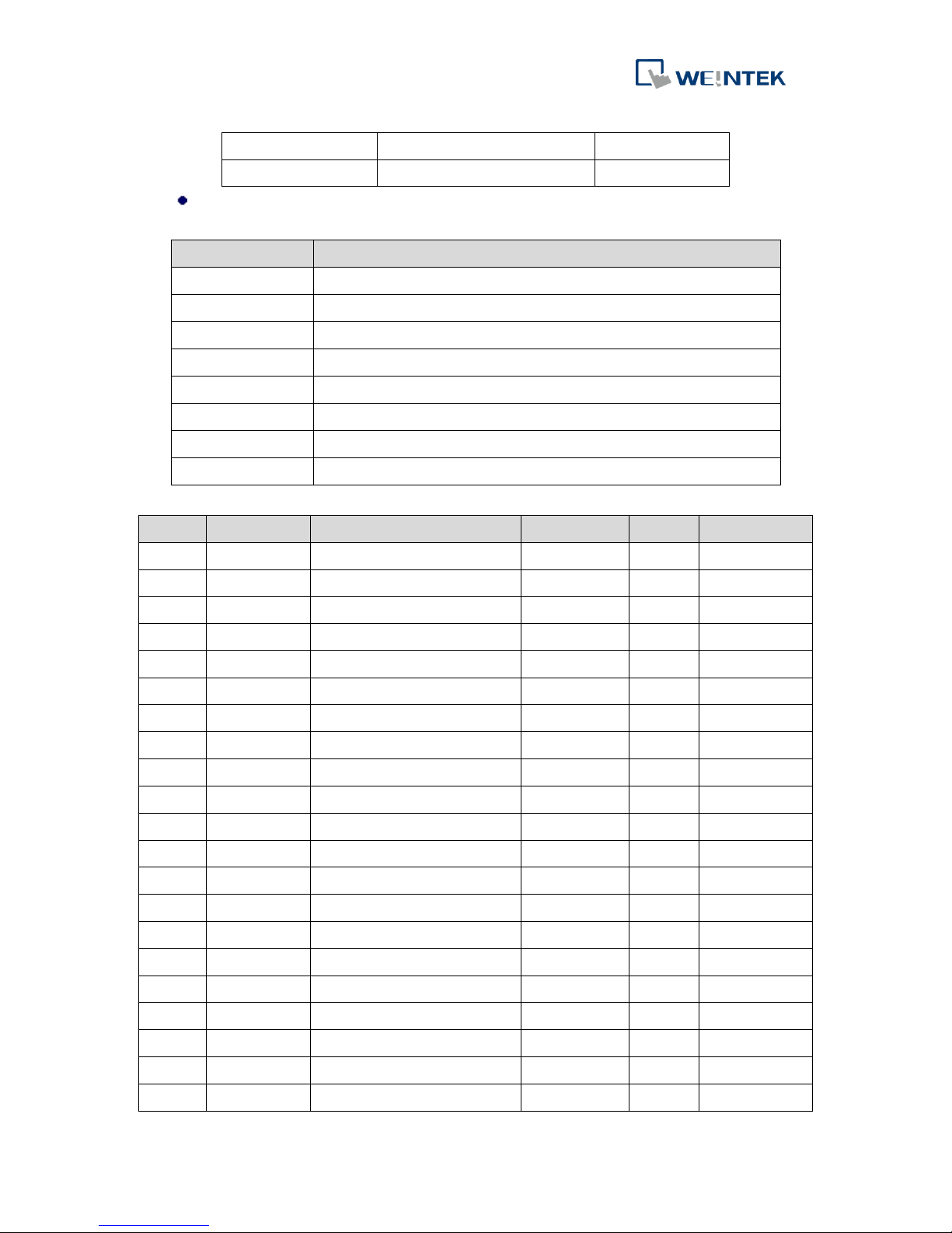
6.2.1 RxPDO Communication Parameter
Index
Sub-index
Description
Type
ro/rw
Default
1400h
00h
Number of word index in RPDO1
UNSIGNED8
ro
02h
01h
COB-ID used by RPDO1
UNSIGNED32
rw
200h + Node-ID
02h
Transmission type of RPDO1
UNSIGNED8
ro
FFh
1401h
00h
Number of word index in RPDO2
UNSIGNED8
ro
02h
01h
COB-ID used by RPDO2
UNSIGNED32
rw
300h + Node-ID
02h
Transmission type of RPDO2
UNSIGNED8
ro
FFh
1402h
00h
Number of word index in RPDO3
UNSIGNED8
ro
02h
01h
COB-ID used by RPDO3
UNSIGNED32
rw
400h + Node-ID
02h
Transmission type of RPDO3
UNSIGNED8
ro
FFh
1403h
00h
Number of word index in RPDO4
UNSIGNED8
ro
02h
01h
COB-ID used by RPDO4
UNSIGNED32
rw
500h + Node-ID
02h
Transmission type of RPDO4
UNSIGNED8
ro
FFh
1404h
00h
Number of word index in RPDO5
UNSIGNED8
ro
02h
01h
COB-ID used by RPDO5
UNSIGNED32
rw
8000000
02h
Transmission type of RPDO5
UNSIGNED8
ro
FFh
1405h
00h
Number of word index in RPDO6
UNSIGNED8
ro
02h
01h
COB-ID used by RPDO6
UNSIGNED32
rw
8000000
02h
Transmission type of RPDO6
UNSIGNED8
ro
FFh
1406h
00h
Number of word index in RPDO7
UNSIGNED8
ro
02h
01h
COB-ID used by RPDO7
UNSIGNED32
rw
8000000
02h
Transmission type of RPDO7
UNSIGNED8
ro
FFh
1407h
00h
Number of word index in RPDO8
UNSIGNED8
ro
02h
01h
COB-ID used by RPDO8
UNSIGNED32
rw
8000000
02h
Transmission type of RPDO8
UNSIGNED8
ro
FFh
Word index 01h: COB-ID used by RPDO
Transmission of RxPDO is only possible in NMT state Operational. As shown
below, setting Bit31 to 1 disables the function. Each Node-ID supports four
RxPDO, to use more than four, please find available Node-ID.
Page 24
iR-COP
21
Bit31
Bit30 Bit11
Bit10 Bit0
0/1 (valid/invalid)
Reserved(0)
COB-ID
Word index 02h: Transmission Type of RPDO
00~F0: synchronous, FEh/FFh: event driven
Value
Description
00h
synchronous
…..
…..
…..
…..
F0h
synchronous
F1h
reserved
…..
…..
…..
…..
FDh
reserved
FEh
event-driven (manufacturer-specific)
FFh
event-driven (device profile and application profile specific)
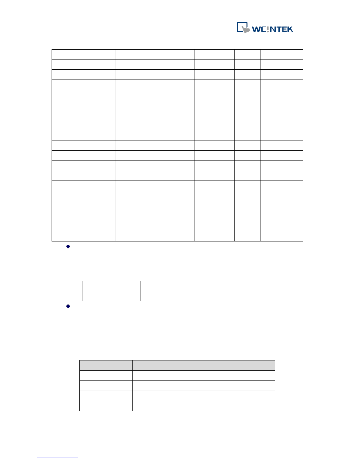
6.2.2 TxPDO Communication Parameter
Index
Sub-index
Description
Type
ro/rw
Default
1800h
00h
Number of word index in TPDO1
UNSIGNED8
ro
05h 01h
COB-ID used by TPDO1
UNSIGNED32
rw
180h + Node-ID
02h
Transmission type of TPDO1
UNSIGNED8
ro
FFh 03h
Inhibit time of TPDO1
UNSIGNED16
rw 0
05h
Event timer of TPDO1
UNSIGNED16
rw 0 1801h
00h
Number of word index in TPDO2
UNSIGNED8
ro
05h 01h
COB-ID used by TPDO2
UNSIGNED32
rw
280h + Node-ID
02h
Transmission type of TPDO2
UNSIGNED8
ro
FFh 03h
Inhibit time of TPDO2
UNSIGNED16
rw 0
05h
Event timer of TPDO2
UNSIGNED16
rw 0 1802h
00h
Number of word index in TPDO3
UNSIGNED8
ro
05h 01h
COB-ID used by TPDO3
UNSIGNED32
rw
380h + Node-ID
02h
Transmission type of TPDO3
UNSIGNED8
ro
FFh 03h
Inhibit time of TPDO3
UNSIGNED16
rw 0
05h
Event timer of TPDO3
UNSIGNED16
rw
0
1803h
00h
Number of word index in TPDO4
UNSIGNED8
ro
05h 01h
COB-ID used by TPDO4
UNSIGNED32
rw
480h + Node-ID
02h
Transmission type of TPDO4
UNSIGNED8
ro
FFh 03h
Inhibit time of TPDO4
UNSIGNED16
rw 0
05h
Event timer of TPDO4
UNSIGNED16
rw
0
1804h
00h
Number of word index in TPDO5
UNSIGNED8
ro
05h
Page 25
iR-COP
22
01h
COB-ID used by TPDO5
UNSIGNED32
rw
8000000
02h
Transmission type of TPDO5
UNSIGNED8
ro
FFh 03h
Inhibit time of TPDO5
UNSIGNED16
rw 0
05h
Event timer of TPDO5
UNSIGNED16
rw 0 1805h
00h
Number of word index in TPDO6
UNSIGNED8
ro
05h 01h
COB-ID used by TPDO6
UNSIGNED32
rw
8000000
02h
Transmission type of TPDO6
UNSIGNED8
ro
FFh 03h
Inhibit time of TPDO6
UNSIGNED16
rw 0
05h
Event timer of TPDO6
UNSIGNED16
rw 0 1806h
00h
Number of word index in TPDO7
UNSIGNED8
ro
05h 01h
COB-ID used by TPDO7
UNSIGNED32
rw
8000000
02h
Transmission type of TPDO7
UNSIGNED8
ro
FFh 03h
Inhibit time of TPDO7
UNSIGNED16
rw 0
05h
Event timer of TPDO7
UNSIGNED16
rw 0 1807h
00h
Number of word index in TPDO8
UNSIGNED8
ro
05h 01h
COB-ID used by TPDO8
UNSIGNED32
rw
8000000
02h
Transmission type of TPDO8
UNSIGNED8
ro
FFh 03h
Inhibit time of TPDO8
UNSIGNED16
rw 0
05h
Event timer of TPDO8
UNSIGNED16
rw
0
Word index 01h: COB-ID used by TPDO
Transmission of TxPDO is only possible in NMT state Operational. As shown
below, setting Bit31 to 1 disables the function. Each Node-ID supports four
TxPDO, to use more than four, please find available Node-ID.
Bit31
Bit30 Bit11
Bit10 Bit0
0/1 (valid/invalid)
Reserved(always 0)
COB-ID
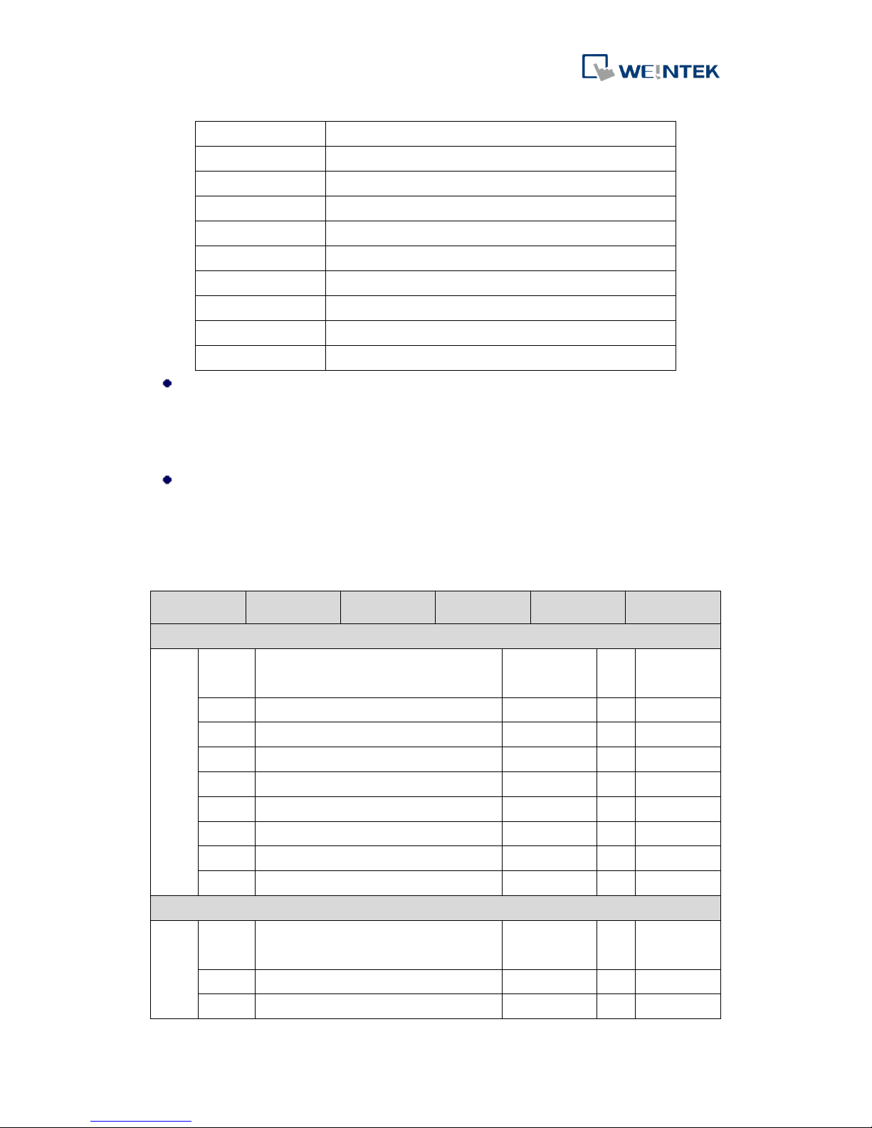
Word index 02h: Transmission Type of TPDO
00~F0: synchronous, transmits PDO when the number of SYNC reaches the
specified number.
FCh: Transmits PDO after receiving RTR.
FDh: Transmits PDO after receiving RTR and triggering event.
FEh/FFh: Transmits PDO when an event is triggered.
Value
Description
00h
synchronous (acyclic)
01 h
synchronous (cyclic every sync)
02 h
synchronous (cyclic every 2nd sync)
03 h
synchronous (cyclic every 3rd sync)
Page 26
iR-COP
23
04 h
synchronous (cyclic every 4th sync)
…..
…..
…..
…..
F0h
synchronous (cyclic every 240th sync)
F1h
reserved
…..
…..
…..
…..
FBh
reserved
FCh
RTR-only (synchronous)
FDh
RTR-only (event-driven)
FEh
event-driven (manufacturer-specific)
FFh
event-driven (device profile and application profile specific)
Word index 03h: Inhibit Time
When Transmission Type of PDO is set to FEh/FFh, the inhibit time specifies the
minimum length of time in 100µs that must be allowed to elapse between the
transmissions. 0 means disabling this function.
Word index 05h: Event Timer
When Transmission Type of PDO is set to FEh/FFh, the Event Timer specifies the
minimum length of time in milliseconds that must be allowed to elapse between
the transmissions. 0 means disabling this function.
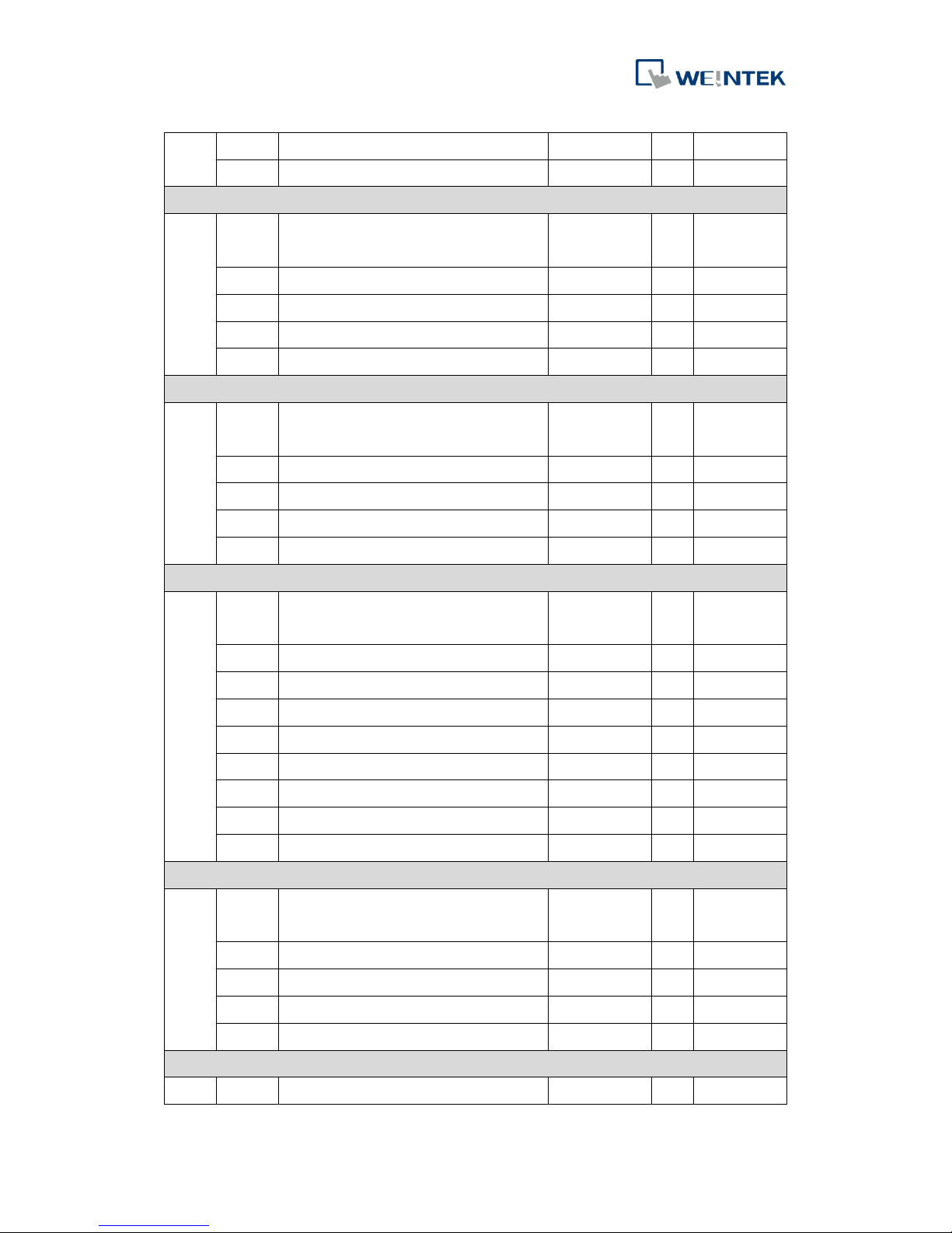
6.2.3 PDO Mapping Parameter
Index
Subindex
Description
Type
ro/
rw
Default
RPDO1 mapping parameter(digital outputs)
1600h
00h
Number of mapped application objects in
RPDO1
UNSIGNED8
rw
08h
01h
1st application object
UNSIGNED32
rw
6200 01 08h
02h
2st application object
UNSIGNED32
rw
6200 02 08h
03h
3st application object
UNSIGNED32
rw
6200 03 08h
04h
4st application object
UNSIGNED32
rw
6200 04 08h
05h
5st application object
UNSIGNED32
rw
6200 05 08h
06h
6st application object
UNSIGNED32
rw
6200 06 08h
07h
7st application object
UNSIGNED32
rw
6200 07 08h
08h
8st application object
UNSIGNED32
rw
6200 08 08h
RPDO2 mapping parameter (analog outputs)
1601h
00h
Number of mapped application objects in
PDO
UNSIGNED8
rw
04h
01h
1st application object
UNSIGNED32
rw
6411 01 10h
02h
2st application object
UNSIGNED32
rw
6411 02 10h
Page 27
iR-COP
24
03h
3st application object
UNSIGNED32
rw
6411 03 10h
04h
4st application object
UNSIGNED32
rw
6411 04 10h
RPDO3 mapping parameter (additional analog outputs)
1602h
00h
Number of mapped application objects in
PDO
UNSIGNED8
rw
04h
01h
1st application object
UNSIGNED32
rw
6411 05 10h
02h
2st application object
UNSIGNED32
rw
6411 06 10h
03h
3st application object
UNSIGNED32
rw
6411 07 10h
04h
4st application object
UNSIGNED32
rw
6411 08 10h
RPDO4 mapping parameter (additional analog outputs)
1603h
00h
Number of mapped application objects in
PDO
UNSIGNED8
rw
04h
01h
1st application object
UNSIGNED32
rw
6411 09 10h
02h
2st application object
UNSIGNED32
rw
6411 0A 10h
03h
3st application object
UNSIGNED32
rw
6411 0B 10h
04h
4st application object
UNSIGNED32
rw
6411 0C 10h
RPDO5 mapping parameter(digital outputs)
1605h
00h
Number of mapped application objects in
PDO
UNSIGNED8
rw
08h
01h
1st application object
UNSIGNED32
rw
6200 09 08h
02h
2st application object
UNSIGNED32
rw
6200 0A 08h
03h
3st application object
UNSIGNED32
rw
6200 0B 08h
04h
4st application object
UNSIGNED32
rw
6200 0C 08h
05h
5st application object
UNSIGNED32
rw
6200 0D 08h
06h
6st application object
UNSIGNED32
rw
6200 0E 08h
07h
7st application object
UNSIGNED32
rw
6200 0F 08h
08h
8st application object
UNSIGNED32
rw
6200 10 08h
RPDO6 mapping parameter (additional analog outputs)
1606h
00h
Number of mapped application objects in
PDO
UNSIGNED8
rw
04h
01h
1st application object
UNSIGNED32
rw
6411 0D 10h
02h
2st application object
UNSIGNED32
rw
6411 0E 10h
03h
3st application object
UNSIGNED32
rw
6411 0F 10h
04h
4st application object
UNSIGNED32
rw
6411 10 10h
RPDO7 mapping parameter (additional analog outputs)
1607h
00h
Number of mapped application objects in
UNSIGNED8
rw
04h
Page 28
iR-COP
25
PDO
01h
1st application object
UNSIGNED32
rw
6411 11 10h
02h
2st application object
UNSIGNED32
rw
6411 12 10h
03h
3st application object
UNSIGNED32
rw
6411 13 10h
04h
4st application object
UNSIGNED32
rw
6411 14 10h
RPDO8 mapping parameter (additional analog outputs)
1608h
00h
Number of mapped application objects in
PDO
UNSIGNED8
rw
04h
01h
1st application object
UNSIGNED32
rw
6411 15 10h
02h
2st application object
UNSIGNED32
rw
6411 16 10h
03h
3st application object
UNSIGNED32
rw
6411 17 10h
04h
4st application object
UNSIGNED32
rw
6411 18 10h
TxPDO communication parameter
1800h
01h
COB-ID used by TPDO1
UNSIGNED32
rw
180h +
Node-ID
1801h
01h
COB-ID used by TPDO2
UNSIGNED32
rw
280h +
Node-ID
1802h
01h
COB-ID used by TPDO3
UNSIGNED32
rw
380h +
Node-ID
1803h
01h
COB-ID used by TPDO4
UNSIGNED32
rw
480h +
Node-ID
1804h
01h
COB-ID used by TPDO5
UNSIGNED32
rw
8000000h
1805h
01h
COB-ID used by TPDO6
UNSIGNED32
rw
8000000h
1806h
01h
COB-ID used by TPDO7
UNSIGNED32
rw
8000000h
1807h
01h
COB-ID used by TPDO8
UNSIGNED32
rw
8000000h
TPDO1 mapping parameter(digital inputs)
1A00h
00h
Number of mapped application objects in
TPDO1
UNSIGNED8
rw
08h
01h
1st application object
UNSIGNED32
rw
6000 01 08h
02h
2st application object
UNSIGNED32
rw
6000 02 08h
03h
3st application object
UNSIGNED32
rw
6000 03 08h
04h
4st application object
UNSIGNED32
rw
6000 04 08h
05h
5st application object
UNSIGNED32
rw
6000 05 08h
06h
6st application object
UNSIGNED32
rw
6000 06 08h
07h
7st application object
UNSIGNED32
rw
6000 07 08h
08h
8st application object
UNSIGNED32
rw
6000 08 08h
Page 29
iR-COP
26
TPDO2 mapping parameter (analog inputs)
1A01h
00h
Number of mapped application objects in
PDO
UNSIGNED8
rw
04h
01h
1st application object
UNSIGNED32
rw
6401 01 10h
02h
2st application object
UNSIGNED32
rw
6401 02 10h
03h
3st application object
UNSIGNED32
rw
6401 03 10h
04h
4st application object
UNSIGNED32
rw
6401 04 10h
TPDO3 mapping parameter (additional analog inputs)
1A02h
00h
Number of mapped application objects in
PDO
UNSIGNED8
rw
04h
01h
1st application object
UNSIGNED32
rw
6401 05 10h
02h
2st application object
UNSIGNED32
rw
6401 06 10h
03h
3st application object
UNSIGNED32
rw
6401 07 10h
04h
4st application object
UNSIGNED32
rw
6401 08 10h
TPDO4 mapping parameter (additional analog inputs)
1A03h
00h
Number of mapped application objects in
PDO
UNSIGNED8
rw
04h
01h
1st application object
UNSIGNED32
rw
6401 09 10h
02h
2st application object
UNSIGNED32
rw
6401 0A 10h
03h
3st application object
UNSIGNED32
rw
6401 0B 10h
04h
4st application object
UNSIGNED32
rw
6401 0C 10h
TPDO5 mapping parameter(digital inputs)
1A04h
00h
Number of mapped application objects in
PDO
UNSIGNED8
rw
08h
01h
1st application object
UNSIGNED32
rw
6000 09 08h
02h
2st application object
UNSIGNED32
rw
6000 0A 08h
03h
3st application object
UNSIGNED32
rw
6000 0B 08h
04h
4st application object
UNSIGNED32
rw
6000 0C 08h
05h
5st application object
UNSIGNED32
rw
6000 0D 08h
06h
6st application object
UNSIGNED32
rw
6000 0E 08h
07h
7st application object
UNSIGNED32
rw
6000 0F 08h
08h
8st application object
UNSIGNED32
rw
6000 10 08h
TPDO6 mapping parameter (additional analog outputs)
1A05h
00h
Number of mapped application objects in
PDO
UNSIGNED8
rw
04h
01h
1st application object
UNSIGNED32
rw
6401 0D 10h
Page 30
iR-COP
27
02h
2st application object
UNSIGNED32
rw
6401 0E 10h
03h
3st application object
UNSIGNED32
rw
6401 0F 10h
04h
4st application object
UNSIGNED32
rw
6401 10 10h
TPDO7 mapping parameter (additional analog outputs)
1A06h
00h
Number of mapped application objects in
PDO
UNSIGNED8
rw
04h
01h
1st application object
UNSIGNED32
rw
6401 11 10h
02h
2st application object
UNSIGNED32
rw
6401 12 10h
03h
3st application object
UNSIGNED32
rw
6401 13 10h
04h
4st application object
UNSIGNED32
rw
6401 14 10h
TPDO8 mapping parameter (additional analog outputs)
1A07h
00h
Number of mapped application objects in
PDO
UNSIGNED8
rw
04h
01h
1st application object
UNSIGNED32
rw
6401 15 10h
02h
2st application object
UNSIGNED32
rw
6401 16 10h
03h
3st application object
UNSIGNED32
rw
6401 17 10h
04h
4st application object
UNSIGNED32
rw
6401 18 10h
6.2.4 Mapping Parameter
Sub Index 00h:
Value
Description
00h
Mapping disabled
01h
Sub-index 01h valid
….
….
08h
Sub-index 01-08h valid
Sub Index 01h ~08h:
31 16
15 8
7 0
Index
Sub-index
Length
MSB
LSB
6.3 I/O Device Object Dictionay
6.3.1 Read digital input
Index
Subindex
Description
Type
ro/
rw
Default
6000h
Read digital input (8-bit)
00h
Number of Digital inputs
UNSIGNED8
ro
40h 01h
Read input 001h to 008h
UNSIGNED8
ro
----
…..
………
40h
Read input 1F8h to 200h
UNSIGNED8
ro
----
Page 31
iR-COP
28
6020h
Read digital input (1-bit)
00h
Number of Digital inputs
UNSIGNED8
ro
80h 01~80h
Read input 001h~080h
UNSIGNED8
ro 0 6021h
Read digital input (1-bit)
00h
Number of Digital inputs
UNSIGNED8
ro
80h 01~80h
Read input 081h~0FFh
UNSIGNED8
ro 0 6021h
Read digital input (1-bit)
00h
Number of Digital inputs
UNSIGNED8
ro
80h 01~80h
Read input 100h~180h
UNSIGNED8
ro 0 6022h
Read digital input (1-bit)
00h
Number of Digital inputs
UNSIGNED8
ro
80h 01~80h
Read input 181h~1FFh
UNSIGNED8
ro 0 6100h
Read digital input (16-bit)
00h
Number of Digital inputs
UNSIGNED8
ro
20h 01h
Read input 001h to 010h
UNSIGNED16
ro
---- …..
………
20h
Read input 1F0h to 200h
UNSIGNED16
ro
----
6120h
Read digital input (32-bit)
00h
Number of Digital inputs
UNSIGNED8
ro
10h 01h
Read input 001h to 020h
UNSIGNED32
ro
---- …..
………
10h
Read input 1E0h to 200h
UNSIGNED32
ro
----
Page 32
iR-COP
29
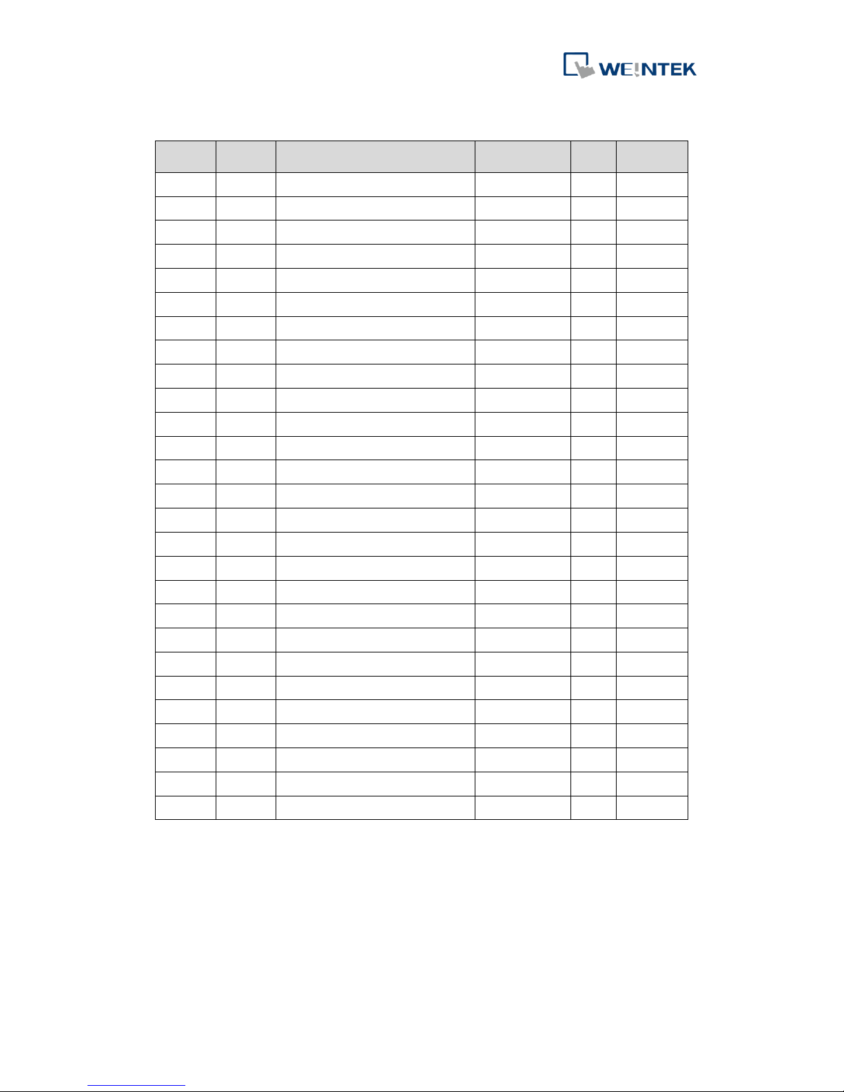
6.3.2 Write digital output
Index
Subindex
Description
Type
ro/
rw
Default
6200h
Write digital output (8-bit)
00h
Number of Digital outputs
UNSIGNED8
ro
40h 01h
Write output 001h to 008h
UNSIGNED8
ro
---- …..
………
40h
Write output 1F8h to 200h
UNSIGNED8
ro 0 6220h
Write digital output (1-bit)
00h
Number of Digital outputs
UNSIGNED8
ro
80h 01~80h
Write output 001h~080h
UNSIGNED8
ro 0 6221h
Write digital output (1-bit)
00h
Number of Digital outputs
UNSIGNED8
ro
80h 01~80h
Write output 081h~0FFh
UNSIGNED8
ro 0 6222h
Write digital output (1-bit)
00h
Number of Digital outputs
UNSIGNED8
ro
80h 01~80h
Write output 100h~180h
UNSIGNED8
ro 0 6223h
Write digital output (1-bit)
00h
Number of Digital outputs
UNSIGNED8
ro
80h 01~80h
Write output 181h~1FFh
UNSIGNED8
ro 0 6300h
Write digital output (16-bit)
00h
Number of Digital outputs
UNSIGNED8
ro
20h 01h
Write output 001h to 010h
UNSIGNED16
ro 0
…..
………
20h
Write output 1F0h to 200h
UNSIGNED16
ro 0 6320h
Write digital output (32-bit)
00h
Number of Digital outputs
UNSIGNED8
ro
10h 01h
Write output 001h to 020h
UNSIGNED32
ro 0
…..
………
10h
Write output 1E0h to 200h
UNSIGNED32
ro
0
Page 33
iR-COP
30
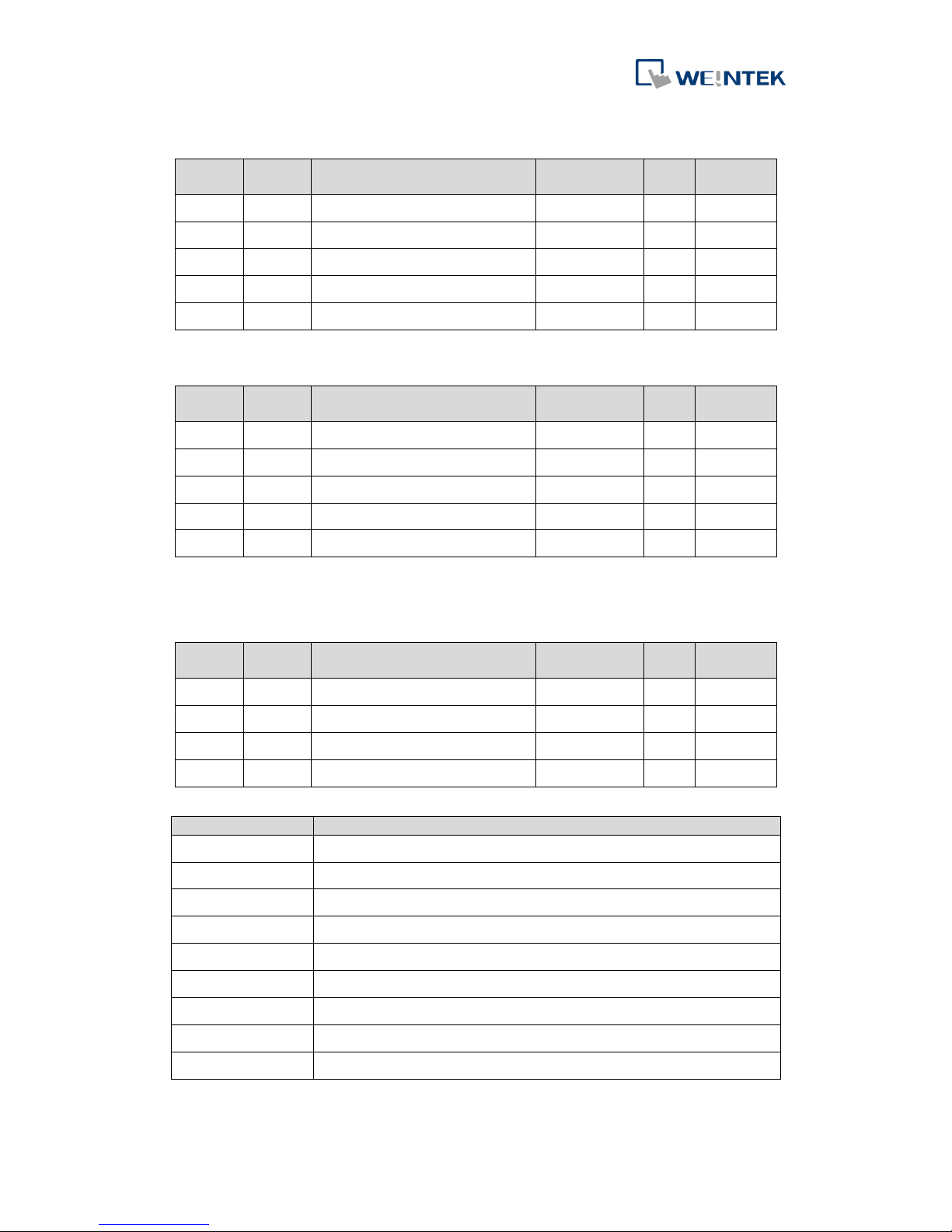
6.3.3 Read Analog input
Index
Subindex
Description
Type
ro/
rw
Default
6401h
Read analog input (16-bit)
00h
Number of analog input
UNSIGNED8
ro
40h 01h
Value of channel 01
INTEGER16
ro 0
…..
………
40h
Value of channel 64
INTEGER16
ro
0
6.3.4 Write Analog output
Index
Subindex
Description
Type
ro/
rw
Default
6411h
Write analog output 16-bit
00h
Number of analog output
UNSIGNED8
rw
40h 01h
Value of channel 01
INTEGER16
rw 0
…..
………
40h
Value of channel 64
INTEGER16
rw
0
6.4 Manufacturer-specific profile area
6.4.1 2000h~2001h: Digital input filter
Index
Subindex
Description
Type
ro/
rw
Default
2000h
00h
Number of digital input
UNSIGNED8
ro
FFh 01-FFh
Digital input 1-255 filter time
UNSIGNED16
rw
0000h
2001h
00h
Number of digital input
UNSIGNED8
ro
FFh 01-FFh
Digital input 1-255 filter time
UNSIGNED16
rw
0000h
6.4.2 3000h~300Fh: Module Registers
Index
Description
3000h
Read/write the 1st module register.
3001h
Read/write the 2nd module register.
3002h
Read/write the 3rd module register.
3003h
Read/write the 4th module register.
3004h
Read/write the 5th module register.
3005h
Read/write the 6th module register.
3006h
Read/write the 7th module register.
……
……
300Fh
Read/write the 16tj module register.
Page 34
iR-COP
31
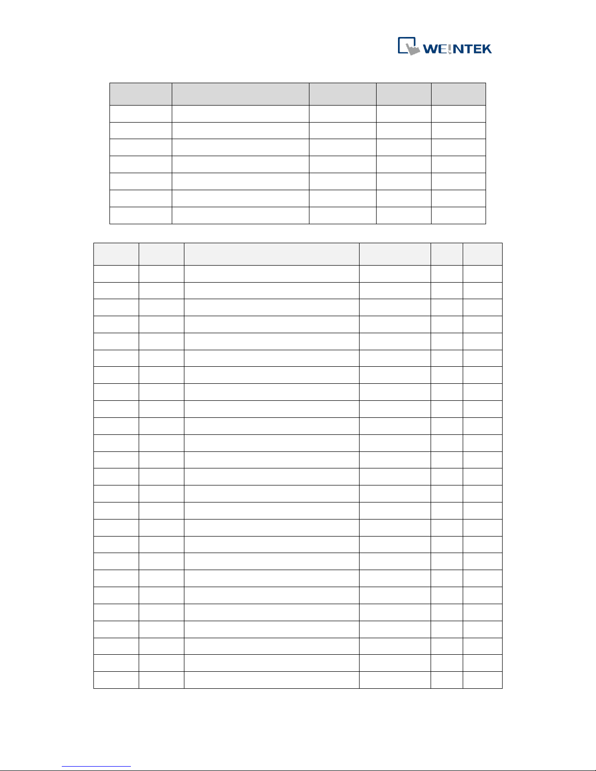
Subindex
Description
Type
ro/
rw
Default
00h
Number of digital inputs
UNSIGNED8
ro
80h
01h
Module register address 0
UNSIGNED16
rw 02h
Module register address 1
UNSIGNED16
rw 03h
Module register address 2
UNSIGNED16
rw 04h
Module register address 3
UNSIGNED16
rw
……
……
……
……
……
80h
Module register address 127
UNSIGNED16
rw
6.4.3 4000h~4007h: iBus and Module Information
Index
Subindex
Description
Type
ro/
rw
Defau
lt
4000h
00h
Number of connected modules.
UNSIGNED16
ro
----- 01h
Reserved
UNSIGNED16
ro
----- 02h
Number of digital inputs.
UNSIGNED16
ro
----- 03h
Number of digital outputs.
UNSIGNED16
ro
----- 04h
Number of analog inputs.
UNSIGNED16
ro
----- 05h
Number of analog outputs.
UNSIGNED16
ro
----- 06h
Total power consumption.
UNSIGNED16
ro
----- 07h
Supported power consumption.
UNSIGNED16
ro
-----
4001h
01h
Firmware version of the 1st module.
UNSIGNED16
ro
-----
02h
Firmware version of the 2nd module.
UNSIGNED16
ro
-----
……
……
……
……
…… 10h
Firmware version of the 16th module.
UNSIGNED16
ro
-----
4002h
01h
Hardware version of the 1st module.
UNSIGNED16
ro
----- 02h
Hardware version of the 2nd module.
UNSIGNED16
ro
----- ……
……
……
……
…… 10h
Hardware version of the 16th module.
UNSIGNED16
ro
-----
4003h
01h
Power consumption of the 1st module.
UNSIGNED16
ro
----- 02h
Power consumption of the 2nd module.
UNSIGNED16
ro
----- ……
……
……
……
…… 10h
Power consumption of the 16th module.
UNSIGNED16
ro
-----
4004h
01h
Number of digital inputs of the 1st module.
UNSIGNED16
ro
----- 02h
Number of digital inputs of the 2nd module.
UNSIGNED16
ro
----- ……
……
……
……
…… 10h
Number of digital inputs of the 16th module.
UNSIGNED16
ro
-----
Page 35
iR-COP
32
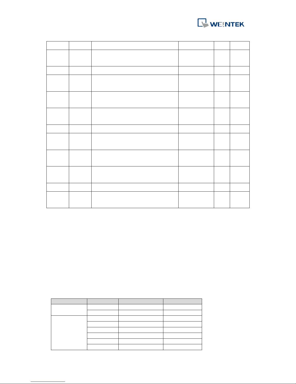
4005h
01h
Number of digital outputs of the 1st module.
UNSIGNED16
ro
02h
Number of digital outputs of the 2nd
module.
UNSIGNED16
ro
……
……
……
……
10h
Number of digital outputs of the 16th
module.
UNSIGNED16
ro 4006h
01h
Number of analog input channels of the 1st
module.
UNSIGNED16
ro
02h
Number of analog input channels of the 2nd
module.
UNSIGNED16
ro
……
……
……
……
10h
Number of analog input channels of the 16th
module.
UNSIGNED16
ro 4007h
01h
Number of analog output channels of the 1st
module.
UNSIGNED16
ro
02h
Number of analog output channels of the
2nd module.
UNSIGNED16
ro
……
……
……
……
10h
Number of analog output channels of the
16th module.
UNSIGNED16
ro
7 Power Consumption
I/O modules use system power supply and external drive power supply, and these
two types of power supply should be calculated separately. Operating coupler and
module requires system power supply while switching I/O and driver requires
external power supply. When calculating power consumption for coupler, the power
needed for the connected modules should be put into the equation. Please consider
power requirements while connecting multiple modules. The following tables show
references on power consumption of couplers and modules.
Type
Device
Consumption(5V)
Power Supply(5V)
Coupler
iR-ETN
220mA/1.1w
2A/10w
iR-COP
170mA/0.85w
2A/10w
Digital I/O
iR-DM16-P
130mA/0.65w
--
iR-DM16-N
130mA/0.65w
--
iR-DQ08-R
220mA/1.1w
--
iR-DQ16-N
205mA/1.02w
iR-DQ16-P
196mA/0.984w
iR-DI16-K
83mA/0.418w
Page 36
iR-COP
33
Analog I/O
iR-AQ04-VI
55mA/0.275w
--
iR-AI04-VI
70mA/0.35W
--
iR-AM06-VI
70mA/0.35W
--
iR-AI04-TR
65mA/0.325w
--
Note:
The coupler is the only power supply for the modules in this system. Please consider power requirements
when connecting multiple modules.
Example:
Device
Name
Consumption
Power Supply
Coupler
iR-COP
170mA/0.85w
2A/10w
Module
iR-DQ08-R *8
220mA*8=1.76A
X
System
Power consumption ∶ 170mA + 1.76A = 1.93 A
Power supply: 2A > 1.93A
8 Connecting Remote I/O using CODESYS
See cMT+CODESYS and Remote I/O manuals.
 Loading...