

Page 1

User
Manual
cMT-SVR Startup Guide
Page 2

Table of Contents
Chapter 1 Overview ............................................................................................................................................. 1
1.1 Specification ....................................................................................................................................... 1
1.2 Dimensions ......................................................................................................................................... 2
1.3 Connector pin designations ............................................................................................................... 4
1.4 USB host port and SD card slot .......................................................................................................... 4
1.5 Ethernet port ...................................................................................................................................... 4
1.6 DIP switch ........................................................................................................................................... 4
1.7 LED indicator ...................................................................................................................................... 5
1.8 CR1225 battery .................................................................................................................................. 5
1.9 Power connection .............................................................................................................................. 5
1.10 How to update cMT-SVR OS image .................................................................................................... 5
Chapter 2 System Setting .................................................................................................................................... 7
2.1 cMT-SVR System Setting .................................................................................................................... 8
2.1.1 Information .................................................................................................................................... 8
2.1.2 System Setting ............................................................................................................................... 9
Chapter 3 How to create a cMT-SVR project ..................................................................................................... 16
3.1 Create a new project ........................................................................................................................ 16
3.2 Download project to cMT-SVR ......................................................................................................... 17
Chapter 4 cMT Viewer App ............................................................................................................................... 18
4.1 Introduction of icons ........................................................................................................................ 18
4.2 How to load project file to cMT Viewer ........................................................................................... 19
4.3 How to open cMT Viewer settings page .......................................................................................... 22
4.4 Monitor Mode .................................................................................................................................. 28
Page 3

cMT-SVR Startup Guide
UM015002E_20190123 Copyright© 2019 Weintek Lab., Inc. All rights reserved.
1
Chapter 1 Overview
1.1 Specification
Page 4

UM015002E_20190123 Copyright© 2019 Weintek Lab., Inc. All rights reserved.
2
1.2 Dimensions
cMT-SVR-100/102
a
USB Host Port
e
Power Connector
b
Ethernet 2 Port
f
SD Card Slot
c
Ethernet 1 Port
g
DIP Switch
d
COM1 RS-232, COM2 RS-485 2W/4W,
COM3 RS-485 2W
h
Reset Button
27,00
[1,063]
125,00
[4,921]
115
[4,520]
130
[5,107]
Front View
Side View
Top View
Bottom View
英文版
a
f
g
h
b
c
d
e
Page 5

UM015002E_20190123 Copyright© 2019 Weintek Lab., Inc. All rights reserved.
3
cMT-SVR-200/202
a
Wi-Fi
e
Power Connector
b
USB Host Port
f
SD Card Slot
c
Ethernet Port
g
DIP Switch
d
COM1 RS-232, COM2 RS-485 2W/4W,
COM3 RS-485 2W
h
Reset Button
英文版 簡中版 日文版
b
c
d
e
a
130mm [5.11"]
115mm [4.52"]
Side View
125mm [4.92"]
27mm [1.06"]
Front View
Top View
f
g
h
b
c
d
e
f
a
115mm [4.52"]
125mm [4.92"]
27mm [1.06"]
g
h
i
Bottom View
Page 6
UM015002E_20190123 Copyright© 2019 Weintek Lab., Inc. All rights reserved.
4
1.3 Connector pin designations
PIN#
COM1 RS-232
COM2 RS-485
COM3 RS-485
2W
4W
1
Data+
2
RxD
3
TxD
4
Data-
5
Ground
6 Data+
RX+
7
Data-
RX-
8
TX+
9
TX-
1.4 USB host port and SD card slot
USB 2.0 full speed host interface supports barcode scanners and USB drive. While using external
hard drive, use external power supply. Do not use USB port to charge external device. You may use
SD card as an expansion of storage.
1.5 Ethernet port
The unit has one/two 10/100/1000M Gigabit Ethernet ports.
The LED indicators on the Ethernet port indicate:
Orange LED: LAN link status
Green LED: Active communication status
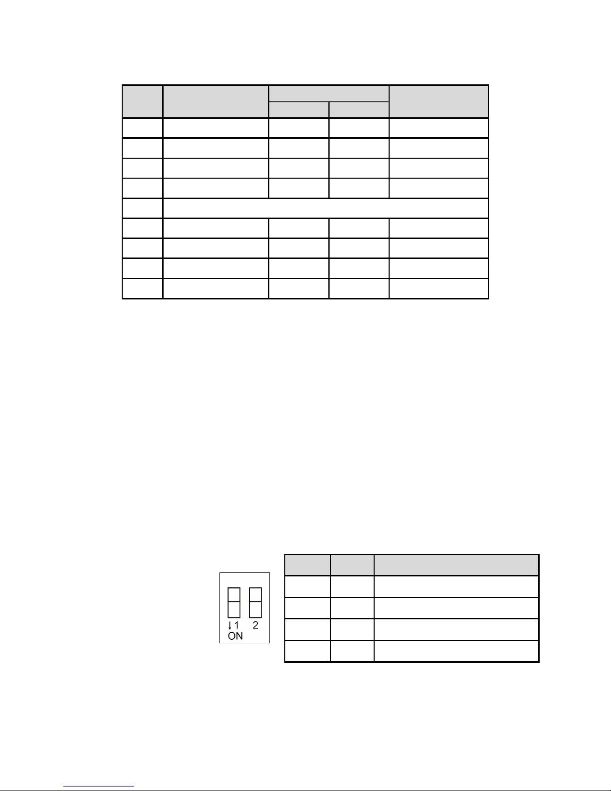
1.6 DIP switch
Each unit is equipped with a reset button and a set of DIP switches. When using the DIP switches to
change modes, the corresponding functions will be triggered.
When SW1 is turned ON and power the unit again, the IP setting is restored to default:
cMT-SVR-100/102
Ethernet 1: DHCP
Ethernet 2: 192.168.100.1
cMT-SVR-200/202
Ethernet 1: DHCP
Wi-Fi: DHCP
Note: Reboot cMT-SVR after adjusting DIP switches to start the corresponding mode. When restore
factory default, the project file and history data stored in the unit are all cleared.
SW1
SW2
Mode
OFF
OFF
Normal mode
ON
OFF
Restore Ethernet IP settings
OFF
ON
Boot loader mode
ON
ON
Restore factory default
Page 7

UM015002E_20190123 Copyright© 2019 Weintek Lab., Inc. All rights reserved.
5
1.7 LED indicator
LED indicators show the operation status of cMT-SVR.
Power (Orange)
Indicates power status.
CPU (Green)
Indicates CPU status.
Communication (Blue)
Indicates communication status. It flashes during communication and
may stay on when communication is good.
1.8 CR1225 battery
The cMT-SVR Series HMI requires a CR1225 coin type lithium battery to keep the RTC running.
Battery type: CR1225 3V lithium battery
1.9 Power connection
Power: The unit can be powered by DC power only, cMT-SVR-100/102 voltage range: 24±20%
Volts DC, cMT-SVR-200/202 voltage range: 10.5~28 Volts DC, compatible with most controller DC
systems.
Note: Connect positive DC line to the‘+’terminal and the DC ground to the‘-’terminal.
1.10 How to update cMT-SVR OS image
Copy the MTfirmware.bin file to SD card, insert the SD card to cMT-SVR and flip DIP Switch 2 to ON.
Restart cMT-SVR and wait about 2 minutes for the system to update OS image. To find the version
number of cMT-SVR OS, please log in System Setting as shown below. (Details can be found in later
chapters.)
Page 8

UM015002E_20190123 Copyright© 2019 Weintek Lab., Inc. All rights reserved.
6
Page 9

UM015002E_20190123 Copyright© 2019 Weintek Lab., Inc. All rights reserved.
7
Chapter 2 System Setting
Connect cMT-SVR via Ethernet cable or Wi-Fi, and configure system settings using the following two
ways.
Set in internet browser
Open internet browser (IE, Chrome, or Firefox), and enter cMT-SVR IP address (for example:
192.168.1.15/web_ihmi) to configure cMT-SVR.
Set on cMT Viewer devices
Launch cMT Viewer App, tap Search, select the cMT-SVR and tap icon to configure.
Page 10
UM015002E_20190123 Copyright© 2019 Weintek Lab., Inc. All rights reserved.
8
2.1 cMT-SVR System Setting
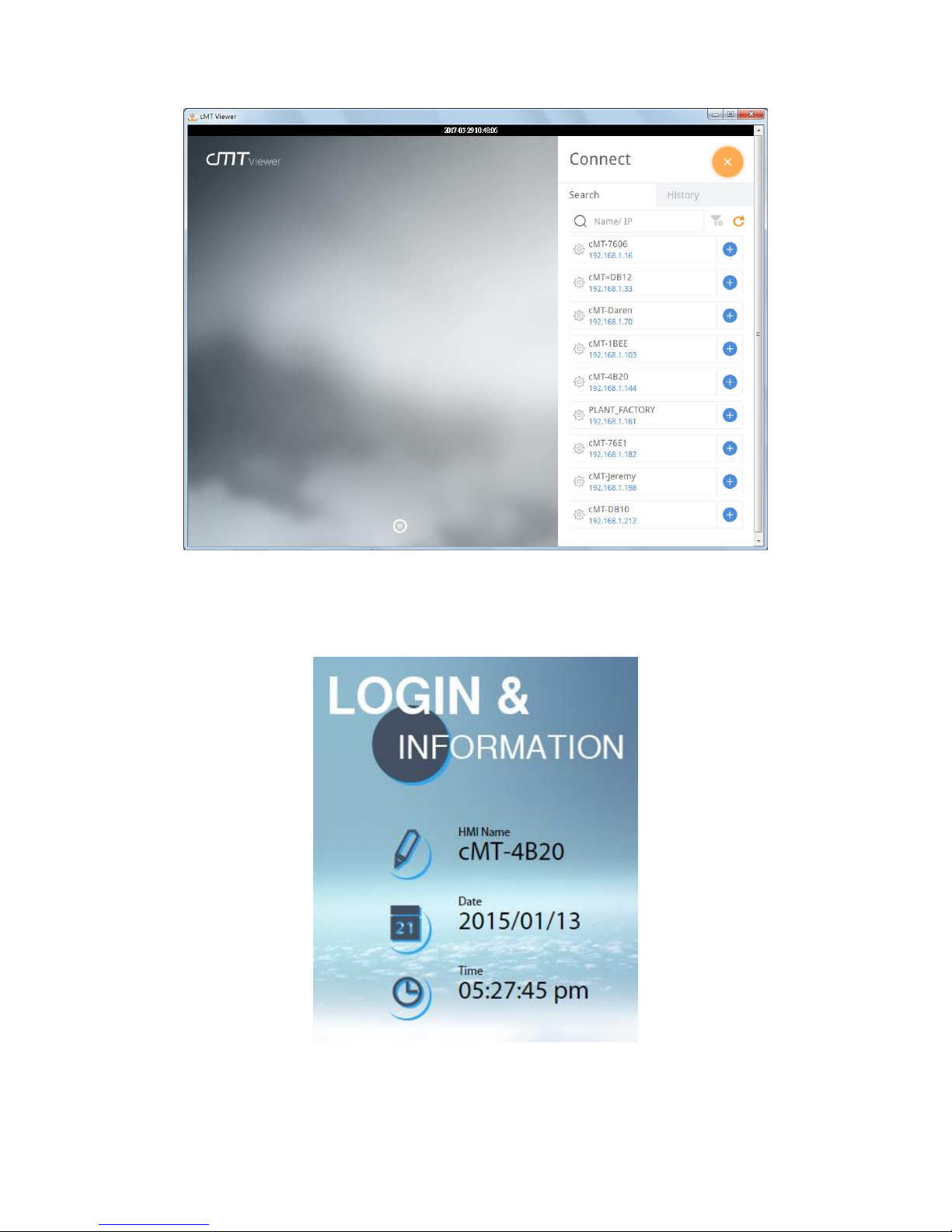
2.1.1 Information
The following part introduces cMT-SVR system information.
Page 11

UM015002E_20190123 Copyright© 2019 Weintek Lab., Inc. All rights reserved.
9
Icon
Description
Displays HMI name.
Displays current date.
Displays current time.
2.1.2 System Setting
The following part introduces cMT-SVR system setting.
There are two modes, [System setting] and [Update]. [System Setting] controls all the settings while
[Update] controls limited items. For safety, specify password for configuration. Enter password to
log in and then select [History] to back up history data.
Page 12
UM015002E_20190123 Copyright© 2019 Weintek Lab., Inc. All rights reserved.
10
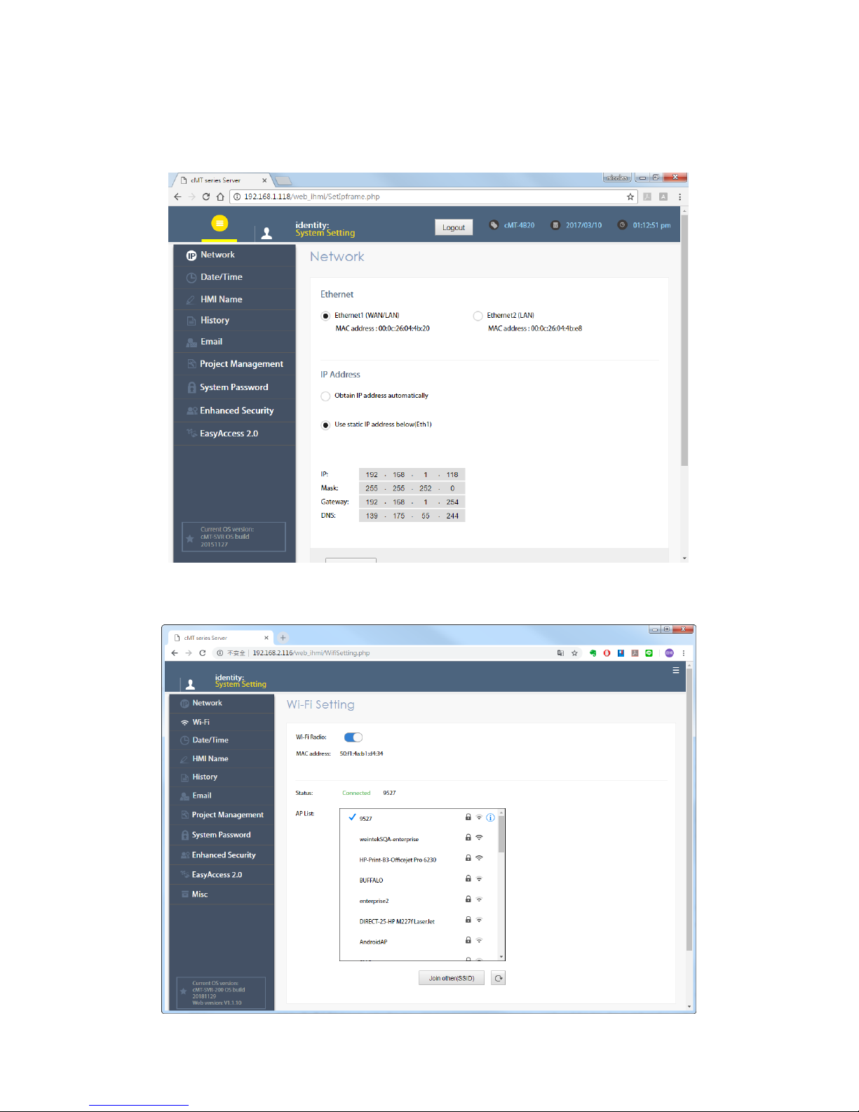
Network
Set the IP address of Ethernet port. cMT-SVR-100/102 has two Ethernet ports while
cMT-SVR-200/202 only has one.
Wi-Fi
cMT-SVR-200/202 can be connected via Wi-Fi. The settings page is shown below.
Page 13
UM015002E_20190123 Copyright© 2019 Weintek Lab., Inc. All rights reserved.
11
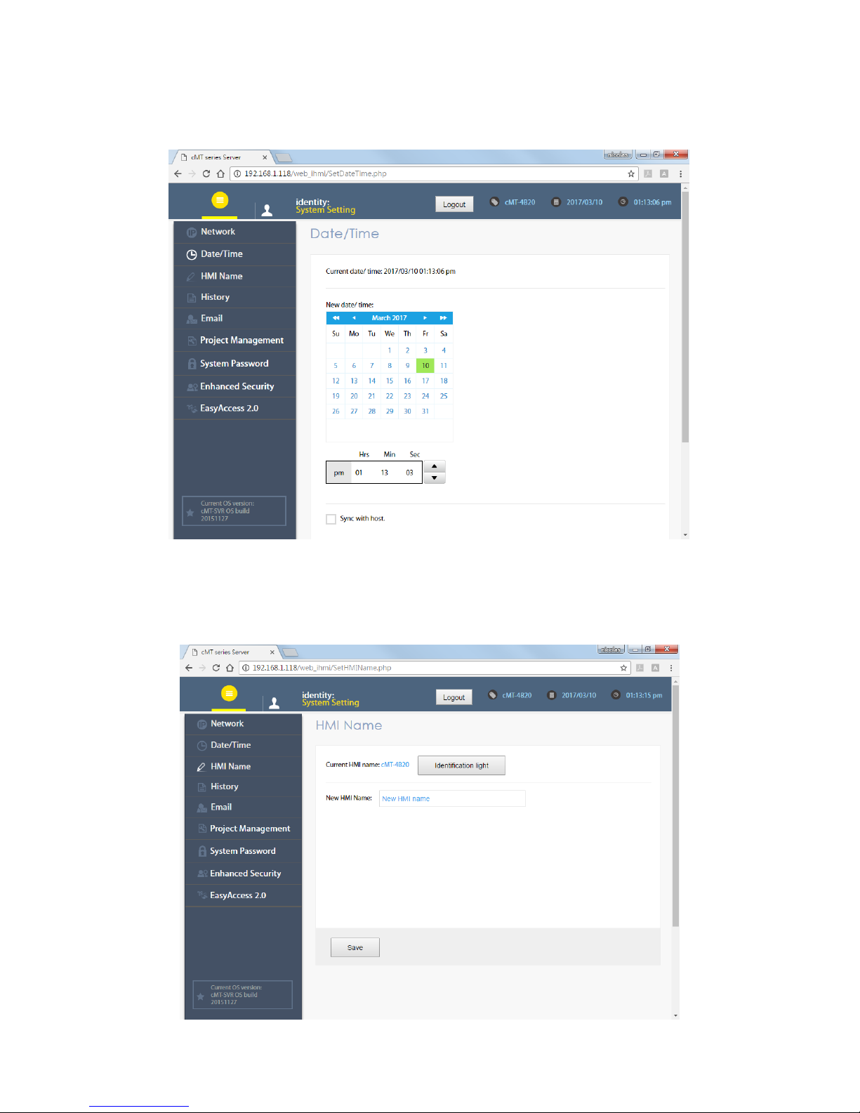
Date/Time
Set time, or select [Sync with host.] to synchronize cMT-SVR time with PC time.
HMI Name
Enter a cMT-SVR name to identify the unit. This saves the trouble of remembering the IP address of
each unit. Click [Identification light] button to turn on the CPU light of the unit. The light flashes 3
times to help finding the unit.
Page 14

UM015002E_20190123 Copyright© 2019 Weintek Lab., Inc. All rights reserved.
12
History
Clear or backup history data in cMT-SVR.
Email
Set the mail address and contact group.
Page 15
UM015002E_20190123 Copyright© 2019 Weintek Lab., Inc. All rights reserved.
13
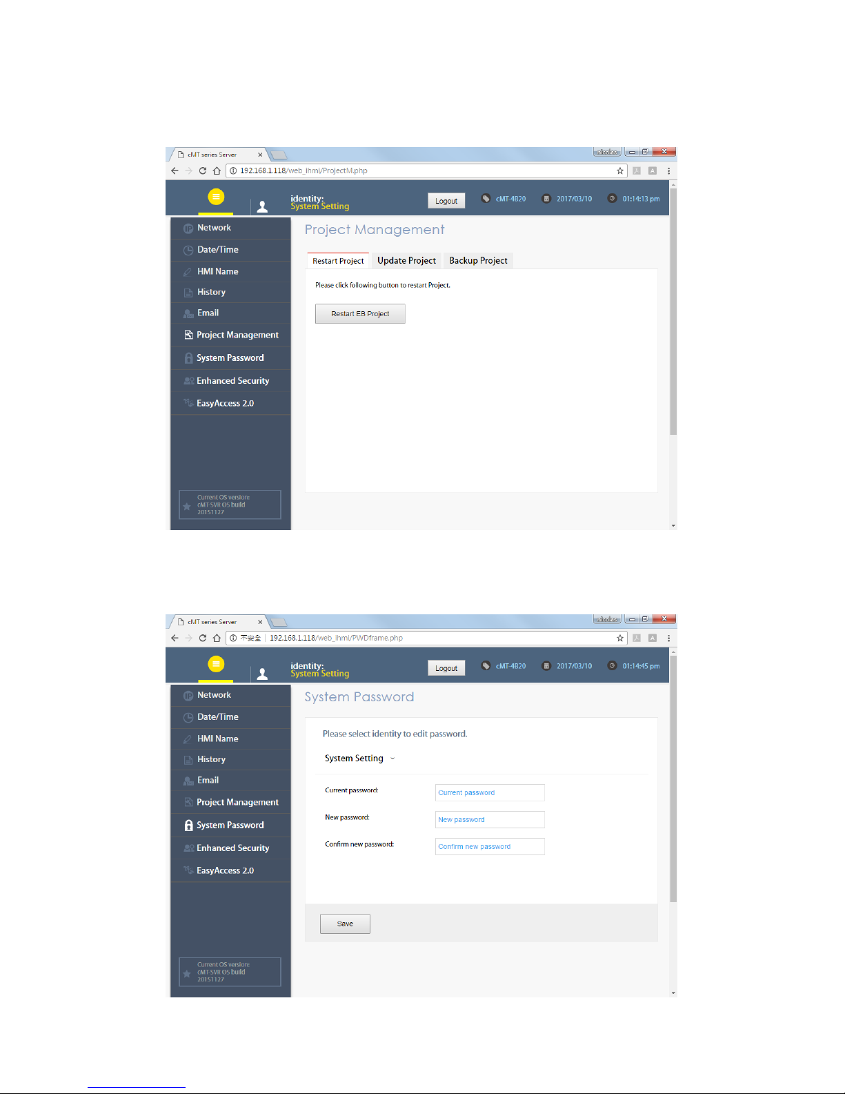
Project Management
Restart, update, or backup project file.
System Password
Set the password for login, and the password for transferring project file and history data.
Page 16

UM015002E_20190123 Copyright© 2019 Weintek Lab., Inc. All rights reserved.
14
Enhanced Security
Set the privilege and password of the account.
EasyAccess 2.0
Activate EasyAccess 2.0 and configure proxy settings.
Page 17
UM015002E_20190123 Copyright© 2019 Weintek Lab., Inc. All rights reserved.
15
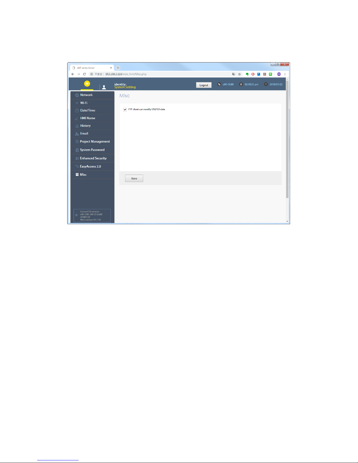
Misc
Miscellaneous settings.
Page 18
UM015002E_20190123 Copyright© 2019 Weintek Lab., Inc. All rights reserved.
16
Chapter 3 How to create a cMT-SVR project
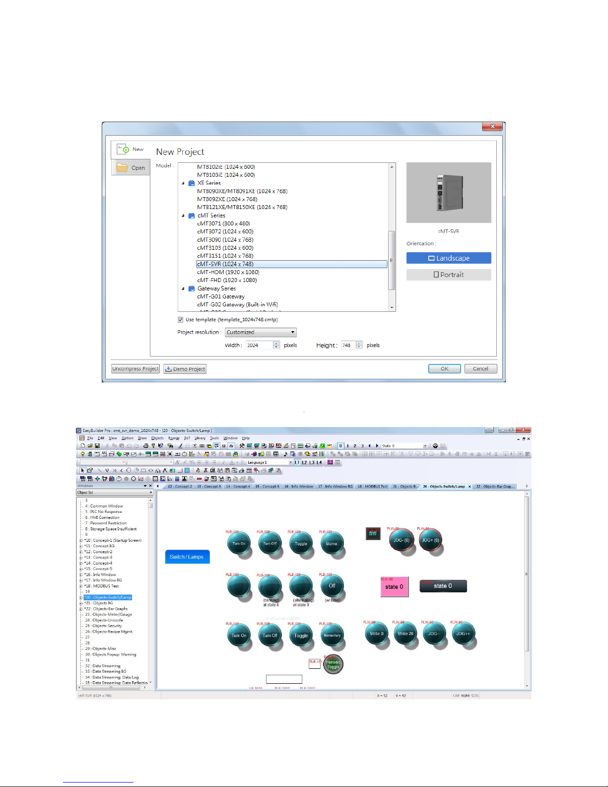
3.1 Create a new project
Step 1. Launch EasyBuilder Pro and select cMT-SVR model.
Step 2. Create the needed objects on editing screen.
Step 3. Save the project and compile to *.cxob file.
Page 19
UM015002E_20190123 Copyright© 2019 Weintek Lab., Inc. All rights reserved.
17
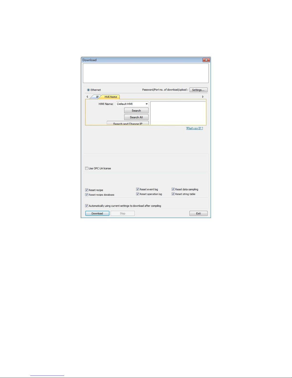
3.2 Download project to cMT-SVR
After compilation, a *.cxob file is generated. The file can be downloaded via Ethernet in EasyBuilder
Pro.
Or, in cMT-SVR System setting, tap Project Management \ Update Project to transfer the project file
from PC to cMT-SVR. Open internet browser (IE, Chrome, Firefox), enter cMT-SVR IP address (for
example: 192.168.1.118/web_ihmi), tap System setting, enter password, and then configure
cMT-SVR settings.
Page 20
UM015002E_20190123 Copyright© 2019 Weintek Lab., Inc. All rights reserved.
18
Chapter 4 cMT Viewer App
cMT Viewer can connect and control cMT Series HMI models. The devices that support cMT Viewer
are: cMT-iV5 (Built-in), iPad/iPhone (Download from iOS® APP Store), AndroidTM (Download from
Google Play), Windows® (in EasyBuilder Pro installation directory).
Please note that:
1. Each cMT Viewer device can simultaneously connect with 4 cMT Series models.
2. Each cMT Viewer device can simultaneously monitor 50 cMT Series models (under Monitor
Mode).
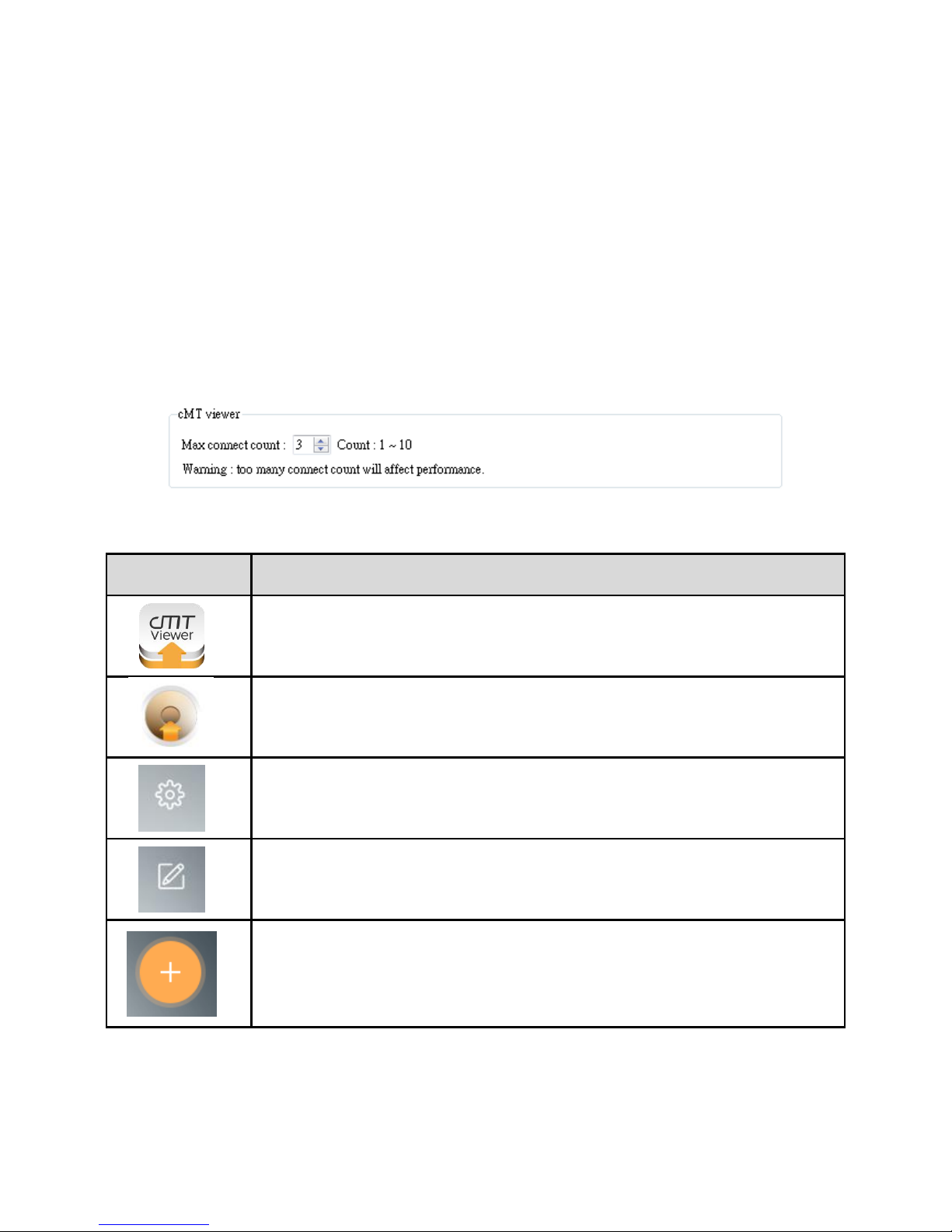
3. Each cMT Series model can simultaneously connect with 1~10 cMT Viewer devices. In
EasyBuilder Pro, open System Parameters » Remote and set [Max. connet count].
4.1 Introduction of icons
Icon
Description
Tap this icon to run cMT Viewer App.
Tap the Start Button when running the project to return to cMT Viewer home
screen.
Tap this icon to configure cMT Viewer.
Tap this icon to change screen layout in Monitor Mode.
Tap this icon to search for all cMT Series HMIs on the same network.
Page 21

UM015002E_20190123 Copyright© 2019 Weintek Lab., Inc. All rights reserved.
19
4.2 How to load project file to cMT Viewer
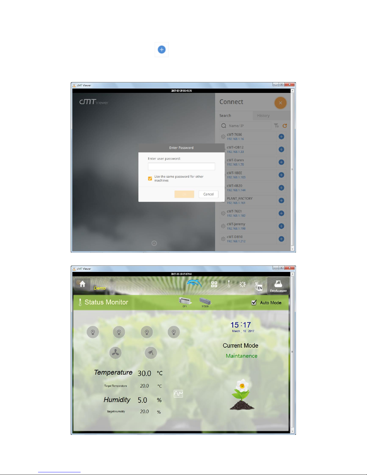
Step 1. Launch cMT Viewer App and tap the + button as shown below.
Step 2. Search for all the cMT Series HMI on the same network.
Page 22
UM015002E_20190123 Copyright© 2019 Weintek Lab., Inc. All rights reserved.
20
Step 3. Select a cMT Series HMI, tap and then enter password. If [Use the same password
for other machines] checkbox is selected, entering password will not be necessary when adding
other cMT Seires HMI that uses the same password.
Step 4. When finished, cMT Viewer will display the project.
Page 23
UM015002E_20190123 Copyright© 2019 Weintek Lab., Inc. All rights reserved.
21
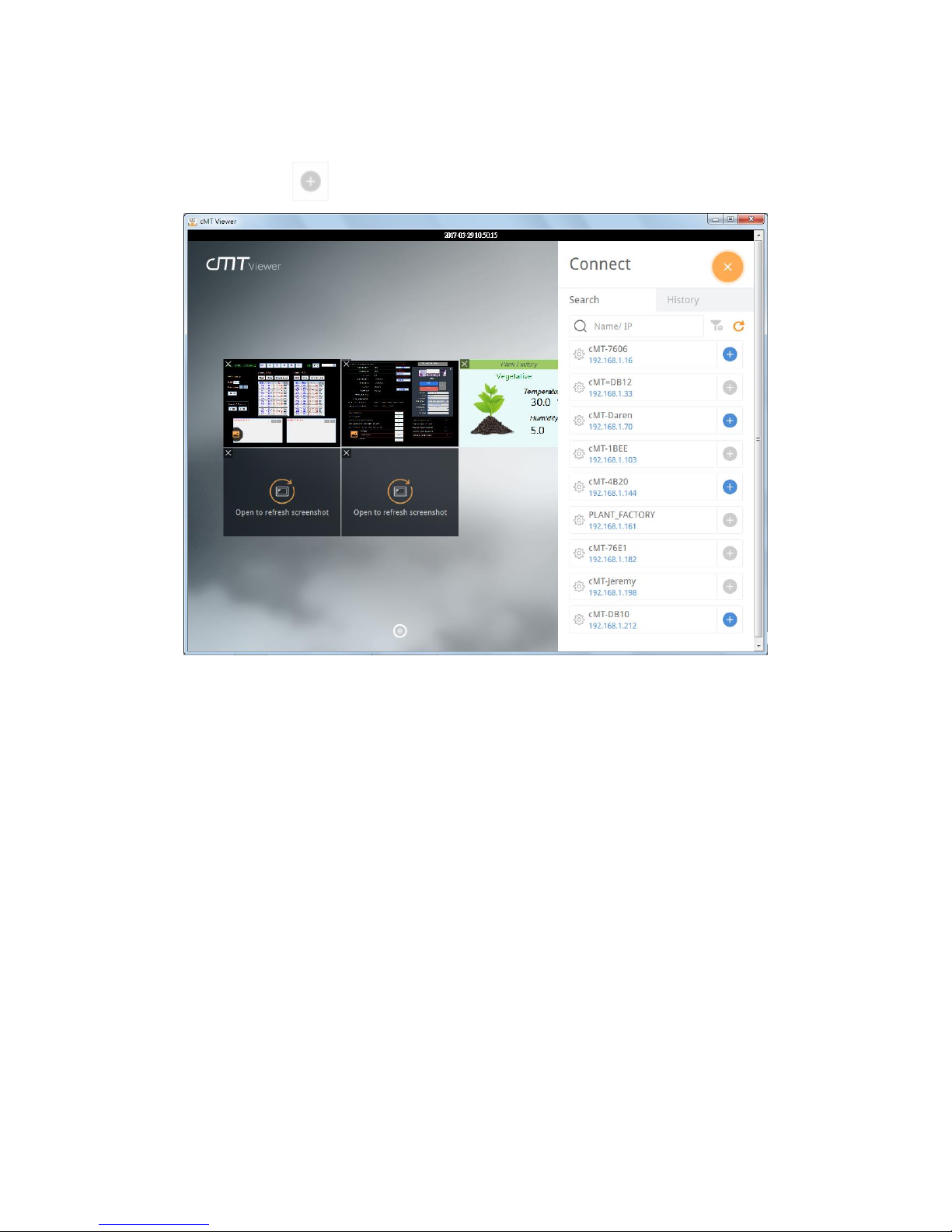
Tap Start Button to return to main screen. To connect another cMT-SVR, follow the preceding
steps to search for cMT-SVR and load the project. The + button of the connected cMT Series
HMI will turn grey:
Page 24
UM015002E_20190123 Copyright© 2019 Weintek Lab., Inc. All rights reserved.
22
4.3 How to open cMT Viewer settings page
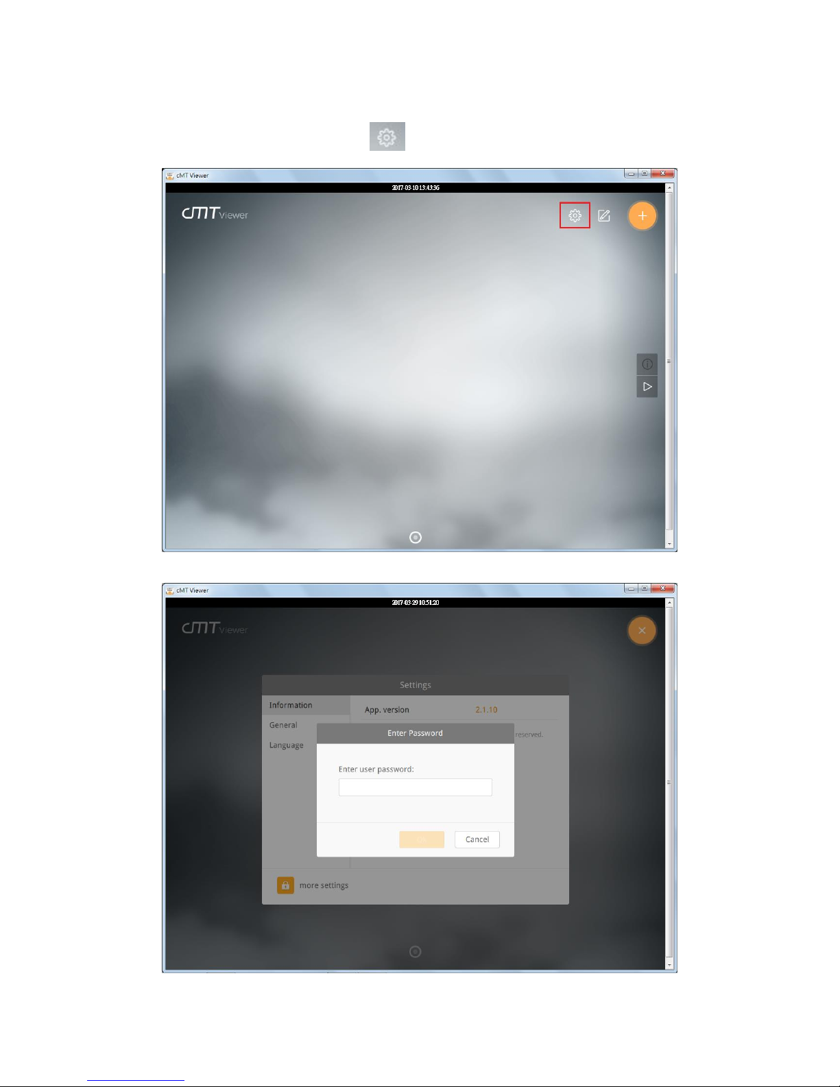
Step 1. In cMT Viewer main screen tap icon.
Step 2. Enter password to open [more settings].
Page 25

UM015002E_20190123 Copyright© 2019 Weintek Lab., Inc. All rights reserved.
23
Information
cMT Viewer version information.
General
cMT Viewer display settings.
Page 26

UM015002E_20190123 Copyright© 2019 Weintek Lab., Inc. All rights reserved.
24
Language
cMT Viewer interface language menu.
Password Protection
After setting, entering password will be necessary for using these functions.
Page 27

UM015002E_20190123 Copyright© 2019 Weintek Lab., Inc. All rights reserved.
25
Open project
If this function is protected by password, adding new cMT Series HMI will require password.
Modify project
If this function is protected by password, changing layout of Monitor Mode will require password.
Page 28

UM015002E_20190123 Copyright© 2019 Weintek Lab., Inc. All rights reserved.
26
Server settings
If this function is protected by password, entering cMT system settings using cMT Viewer will
require password.
Clear history
If this function is protected by password, clearing connection history in History page will require
password.
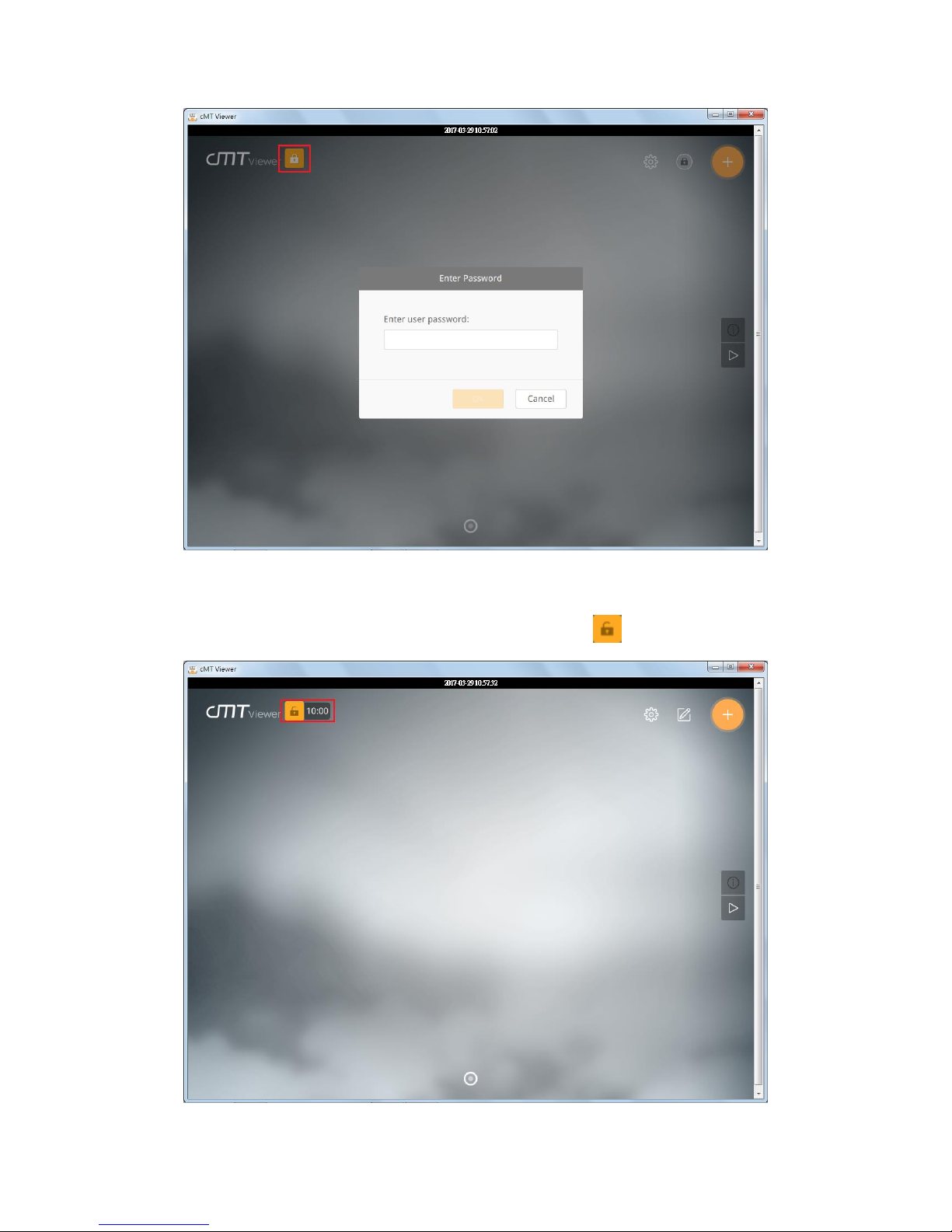
To use password protected functions, tap the lock icon in the upper left corner and enter
password.
Page 29
UM015002E_20190123 Copyright© 2019 Weintek Lab., Inc. All rights reserved.
27
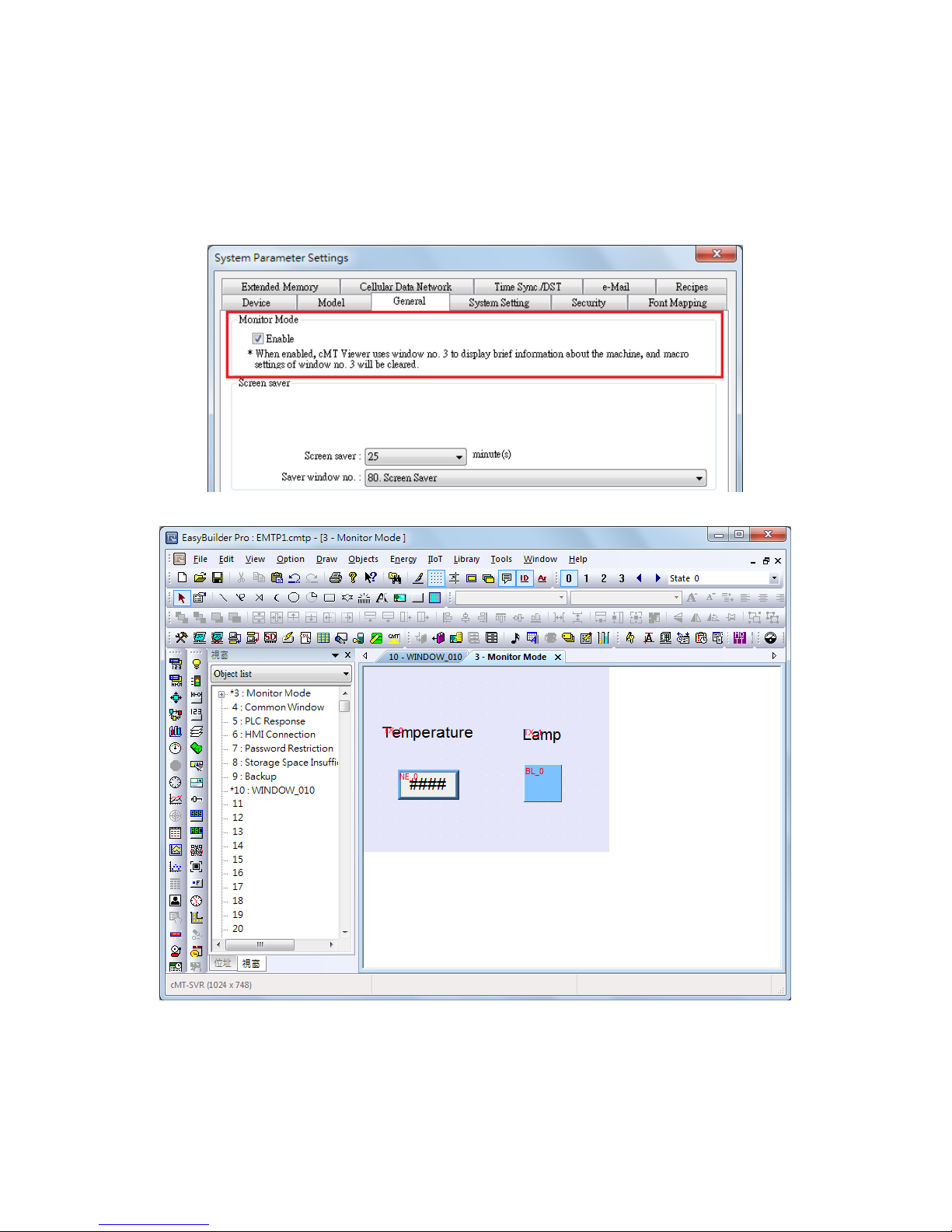
After entering password, cMT Viewer will start a countdown timer of 10 minutes, when it’s over,
the functions protected by password will be locked again. The countdown timer can be reset by
tapping any button in cMT Viewer. To reset the timer to zero, tap .
Page 30
UM015002E_20190123 Copyright© 2019 Weintek Lab., Inc. All rights reserved.
28
4.4 Monitor Mode
cMT Viewer supports Monitor Mode. By placing objects in Window no. 3 in the project, cMT Viewer
screen can be refreshed dynamically. In Monitor Mode, the user can select up to 50 HMIs to
monitor simultaneously, without the need for accessing each cMT.
Step 1. Enable Monitor Mode in EasyBuilder Pro » System Parameter Settings » General tab.
Step 2. Add the needed objects in Window No. 3, which is the Monitor Mode window by default.
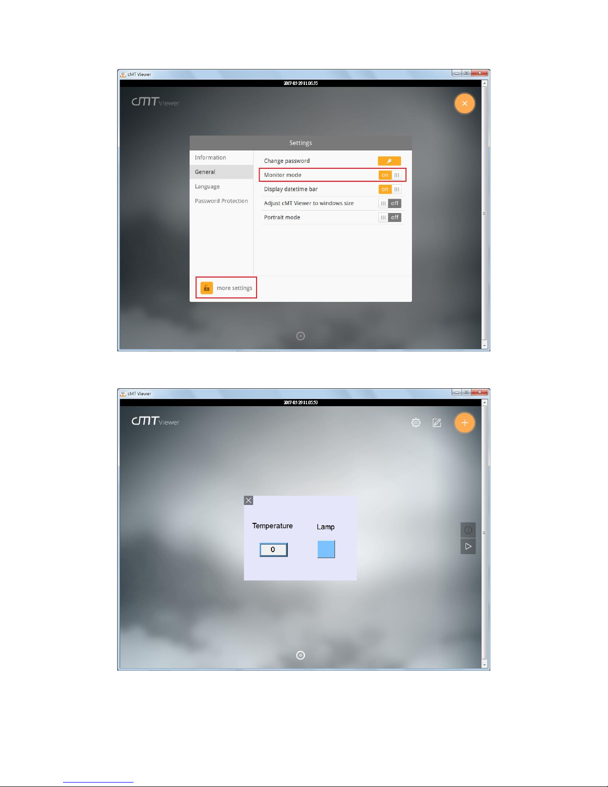
Step 3. Open [more settings] in cMT Viewer, go to General page and enable [Monitor mode].
Page 31
UM015002E_20190123 Copyright© 2019 Weintek Lab., Inc. All rights reserved.
29
Step 4. Download the project file to cMT Series HMI using cMT Viewer, the Monitor Mode
window appears.
Windows is a trademark or a registered trademark of Microsoft Corporation in the United States and/or other countries.
Android is a trademark or a registered trademark of Google, Inc. in the United States and/or other countries.
IOS is a registered trademark of Cisco Systems, Inc. and/or its affiliates in the United States and certain other countries.
Intel Atom is a trademark of Intel Corporation or its subsidiaries in the U.S. and/or other countries.
Other company names, product names, or trademarks in this document are the trademarks or registered trademarks of their respective companies.
This document is subject to change without prior notice.
 Loading...