

Page 1
Installation and Startup Guide
This document covers the installation of cMT-iM21, for the detailed specifications and operation, please
refer to Datasheet, Brochure and User Manual. Please read all warnings, precautions, and instructions on
the device carefully before use.
Install Environment:
Electrical
Environment
The cMT-iM21 Series has been tested to conform to European CE requirements.
This means that the circuitry is designed to resist the effects of electrical noise.
This does not guarantee noise immunity in severe cases. Proper wire routing and
grounding will insure proper operation.
Environmental
Considerations
(1) Make sure that the units are installed correctly and that the operating limits
are followed. Avoid installing units in environments where severe
mechanical vibration or shocks are present.
(2) Do not operate the unit in areas subject to explosion hazards due to
flammable gases, vapors or dusts.
(3) Do not install the unit where acid gas, such as SO2 exists.
(4) This device should be mounted in the vertical position and for use on the flat
surface enclosure.
(5) Relative Humidity: 10% ~ 90% (non-condensing)
Cleaning
Considerations
Clean the device using dry cloths. Do not use liquid or spray detergents for
cleaning.
IP rating
IP 65
Warning
Protection impairment if used in a manner not specified by the manufacturer.
Déficit de protection si utilisé d'une manière non spécifiée par le fabricant.
Unpacking the Unit
Unpack and check the delivery. If damage is found, notify the supplier.
NOTE: Place the unit on a stable surface during installation. Dropping it or letting it fall may cause
damage.
(1) Installation Instruction, 2-sided A4 *1
(2) cMT-iM21 *1
(3) Panel mount kit
Installation Instructions
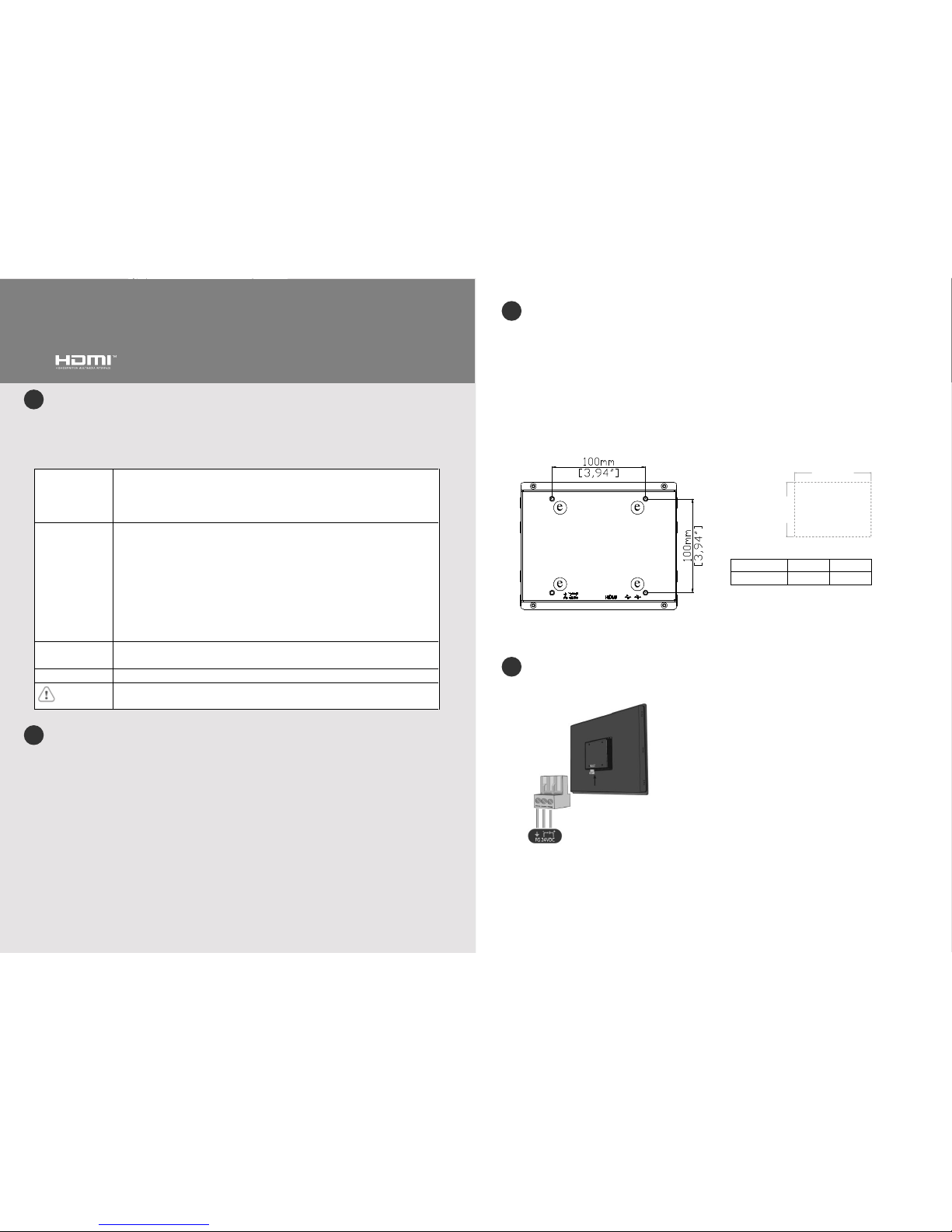
Use a control box that provides enough stiffness. Cutout Dimension: 532 mm x 340 mm. Secure the
operator panel in position, using all the fastening holes and the provided brackets and screws. Screw
Torque: 2.6 ~ 3.9 lbf.in. (For reaching waterproof effect and preventing the panel from being deformed.)
Plan for adequate space around the unit and inside the enclosure, for ventilation and cables. Consider the
heat from other devices inside the enclosure. The ambient temperature around the unit must be 0 ~ 50°C
Minimum required clearances (along the overlay): Top 20 mm / Bottom 20 mm / Sides 20 mm
Maximum panel thickness: 3 mm
VESA Mount 100 x 100 (M4 Max. Depth 8mm)
Power Connections
NOTE: Connect positive DC line to the ‘+’ terminal and the DC ground to the ‘-’ terminal.
Type
A(mm)
B(mm)
cMT-iM21
532
340
cMT-iM21 series
Installation Instruction
3
4 1 2
(A)
(B)
Cutout
Page 2
System Settings
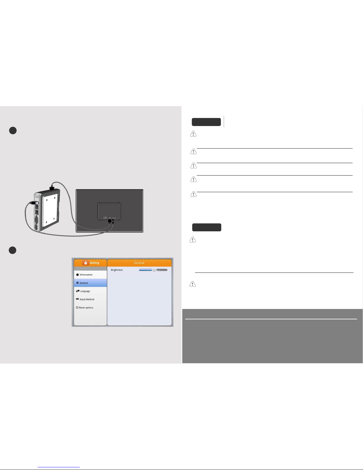
Connect cMT-iM21 with cMT-FHD using HDMITM cable for digital signal and USB cable for touch signal
Cable length: <5m
When the cable length needed exceeds 5m, please use a device or cable that can ensure better signal
strength.
While cMT-FHD’s USB port is occupied by the USB cable used for touch signal, cMT-iM21 offers an
additional USB port that can be used for another USB device, and this USB device will work as if being
connected to cMT-FHD.
Information
After connecting cMT-iM21 with
cMT-FHD, open cMT-FHD settings to
adjust Brightness.
The terms HDMI, HDMI High-Definition Multimedia Interface, and the HDMI Logo are trademarks or
registered trademarks of HDMI Licensing Administrator, Inc.
Limited Warranty
This product is limited warranted against defects in design and manufacture. The proven
defective product will either be repaired or replaced, at Weintek’s discretion. This warranty
shall not cover any product which is
(a) Out of warranty period which is 12 months from the manufacturing month of the HMI products.
(b) Damage caused by Force Majeure, accident, negligence, improper installation or misuse.
(c) Product has been repaired or taken apart by unauthorized technicians.
(d) Products whose identification markings have been removed or damaged.
5
6
Power
Use power output that meets SELV (Safety Extra-Low Voltage) requirements. The unit can be
powered by DC power only, voltage range: 24±20% Volts DC, compatible with most controller DC
systems. The power conditioning circuitry inside the unit is accomplished by a switching power
supply. The peak starting current can be as high as 2A. Power supply: 24V 50W (above).
High
Voltage
DC voltage sources should provide proper isolation from main AC power and similar hazards.
Emergency
Stop
A Hard-wired EMERGENCY STOP should be fitted in any system using cMT-iM21 to comply with
ICS Safety Recommendations.
Supply
Voltage
Condition
Do not power the unit and inductive DC loads, or input circuitry to the controller, with the same
power supply. Note: The 24 VDC output from some controllers may not have enough current to
power the unit.
Wire
Routing
a. Power wire length should be minimized (Max: 500m shielded, 300m unshielded).
b. Please use twisted pair cables for power wire and signal wire and conform to the impedance
matching.
c. If wiring is to be exposed to lightning or surges, use appropriate surge suppression devices.
d. Keep AC, high energy, and rapidly switching DC power wiring separated from signal wires.
e. Add a resistor and capacitor in the parallel connection between the ungrounded DC power
supply and the frame ground. This provides a path for static and high frequency dissipation.
Typical values to use are 1M Ohm and 4700pF.
CAUTION
NOTE: Make sure that all local and national electrical standards are met when
installing the unit. Contact your local authorities to determine which codes apply.
Hardware
Considerations
The system designer should be aware that devices in Controller systems could fail and thereby
create an unsafe condition. Furthermore, electrical interference in an operator interface can lead to
equipment start-up, which could result in property damage and/or physical injury to the operator.
If you use any programmable control systems that require an operator, be aware that this potential
safety hazard exists and take appropriate precautions. Although the specific design steps depend on
your particular application, the following precautions generally apply to installation of solid-state
programmable control devices, and conform to the guidelines for installation of Controllers
recommended in NEMA ICS 3-304 Control Standards.
Programming
Considerations
To conform with ICS Safety Recommendations, checks should be placed in the controller to ensure
that all writable registers that control critical parts of plant or machinery have limit checks built into
the program, with an out-of-limit safe shut down procedure to ensure safety of personnel.
GMECM2100_cMT_iM21_Installation_181107
DANGER
 Loading...