

Page 1
5305 Spectrum Drive, Frederick, MD 21703-7362 TEL: 301-846-9222, 800-638-2048 Fax: 301-846-9116
web: www.aeroflex-weinschel.com email: [email protected]
200
Revision Date: 12/15/04
Power Splitters & Dividers
NOTE: All dimensions are given in mm (inches) and are
maximum, unless otherwise specified.
Frequency (GHz) Maximum SWR
dc - 2 1.05
2 - 4 1.07
4 - 8 1.10
8 - 18 1.15
* When used in a leveling or ratio system.
Model 1870A dc to 18.0 GHz
Broadband Resistive Power Splitter 1 Watt
(Matching)
Type N Connectors
Features
These resistive power splitters are intended for RF and
wireless applications in which one of the two outputs is
included in a leveling loop or is used as a reference in a
ratio system, for the purpose of providing an output signal
whose source impedance is essentially matched to 50Ω.
Some examples are:
o A dual channel insertion loss measuring system
(ratio).
o A parallel IF substitution insertion loss measuring
system (ratio or ALC loop).
o A precision power source (ratio or ALC loop).
Specifications
NOMINAL IMPEDANCE: 50 Ω
FREQUENCY RANGE: dc to 18.0 GHz
INSERTION LOSS: 6 dB nominal, 7.5 dB maximum
(Between Input and either output).
MAXIMUM INPUT POWER: 1 watt average, 1 kilowatt
peak (Input connector only)
PHASE TRACKING: +2° nominal between output ports
POWER COEFFICIENT: < 0.005 dB/dB/watt
TEMPERATURE COEFFICIENT: <0.0004 dB/dB/°C
TEMPERATURE RANGE: -55°C to +85°C
CONSTRUCTION: Nickel plated brass body; stainless
steel connectors; gold plated beryllium copper contacts.
EQUIVALENT OUTPUT SWR (Port 2 & 3):
OUTPUT TRACKING (Between Ports):
Frequency (GHz) Tracking
(maximum dB)
dc - 8 0.15
8 -18 0.20
TEST DATA: Insertion Loss, SWR, and Tracking measurements performed across the frequency band. Test data
available at additional cost.
CONNECTORS: Type N female connectors per MIL-STD348 interface dimensions - mate nondestructively with
MIL-C-39012 connectors.
WEIGHT: Net 170 g (6 oz)
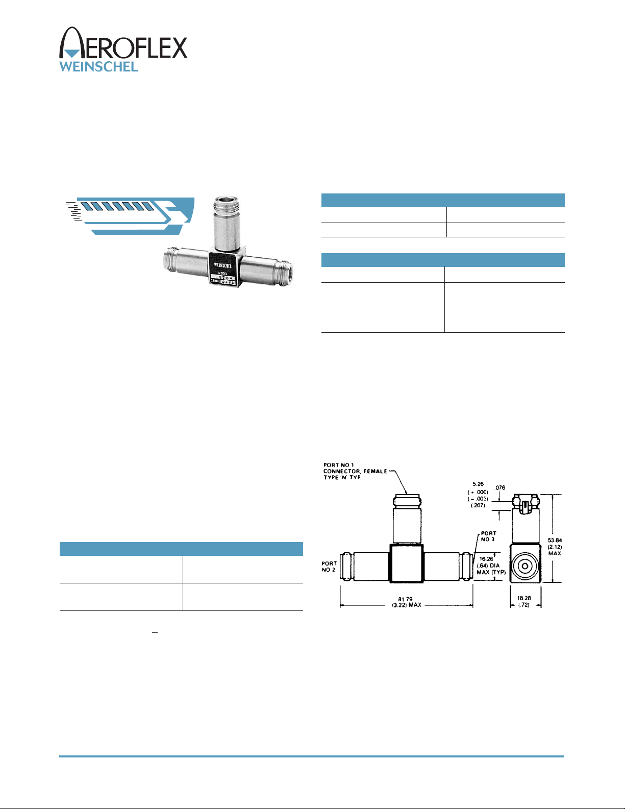
PHYSICAL DIMENSIONS:
MAXIMUM INPUT SWR:
Frequency (GHz) Maximum SWR
dc - 18 1.30
E PX R
www.sicklesonline.com
E SS
800-542-4457
 Loading...