

Page 1
LumeroTel 2 867/868/915 MHz
28225.0001, 28226.0001,
28227.0001, 28225.0901,
28226.0901, 28227.0901
0682
Operating instructions (translation)
181226401_ENT_0213
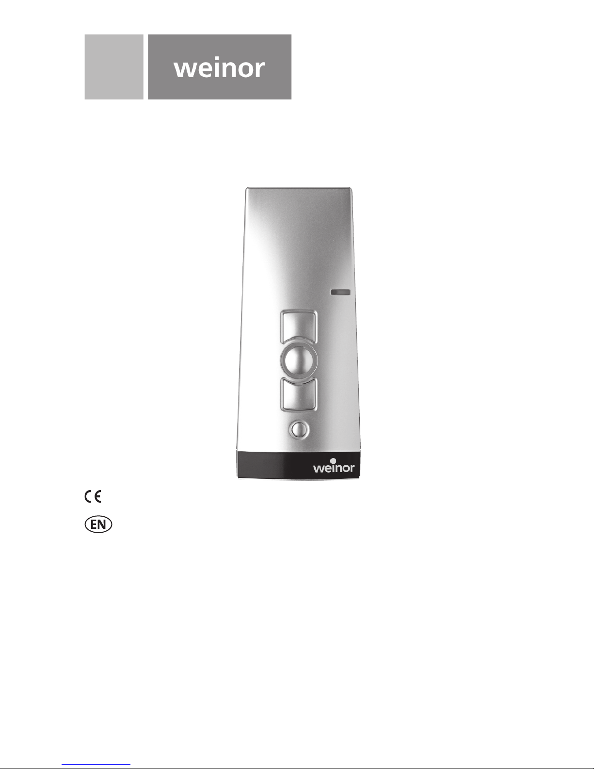
BiEasy 1M
Page 2
© weinor GmbH & Co. KG 2 | EN © weinor GmbH & Co. KG EN | 3
Contents
Safety instructions . . . . . . . . . . . . . . . . . . . . . . . . . . . 3
Safety instructions for radio operation . . . . . . . . . . . 4
Intended use . . . . . . . . . . . . . . . . . . . . . . . . . . . . . . . . 4
Exclusion of liability . . . . . . . . . . . . . . . . . . . . . . . . . . 5
Scope of delivery . . . . . . . . . . . . . . . . . . . . . . . . . . . . . 5
Technical data . . . . . . . . . . . . . . . . . . . . . . . . . . . . . . . 5
Mounting of wall bracket . . . . . . . . . . . . . . . . . . . . . . 6
Description of the device . . . . . . . . . . . . . . . . . . . . . . 7
Explanation of functions . . . . . . . . . . . . . . . . . . . . . . . 8
Bidirectional radio system . . . . . . . . . . . . . . . . . . . . . 8
Initial operation . . . . . . . . . . . . . . . . . . . . . . . . . . . . . 8
Programming the transmitter . . . . . . . . . . . . . . . . . 10
Programming additional transmitters . . . . . . . . . . . 11
Synchronized programming mode . . . . . . . . . . . . . 12
Stopping programming mode (bidirectional) in
the transmitter . . . . . . . . . . . . . . . . . . . . . . . . . . . . . 13
Approaching end positions of roller shutter /
awning / Venetian blind . . . . . . . . . . . . . . . . . . . . . . 13
Operation of the transmitter using Combio JA Pulse 16
Deleting positions/deleting transmitters . . . . . . . . . 16
Replacing the battery . . . . . . . . . . . . . . . . . . . . . . . . 17
Cleaning . . . . . . . . . . . . . . . . . . . . . . . . . . . . . . . . . . . 18
Disposal . . . . . . . . . . . . . . . . . . . . . . . . . . . . . . . . . . . 18
Troubleshooting . . . . . . . . . . . . . . . . . . . . . . . . . . . . 18
Repair . . . . . . . . . . . . . . . . . . . . . . . . . . . . . . . . . . . . . 18
EC Declaration of conformity . . . . . . . . . . . . . . . . . . 20
Address . . . . . . . . . . . . . . . . . . . . . . . . . . . . . . . . . . . 21
Safety instructions
Observance of these instructions is a
precondition for safe and fault-free operation and
for the product performing as intended.
• The operator/user shall have read the instructions fully and
understand them.
• The operator shall ensure that the instructions are available to
the user in a legible form.
• The operator shall ensure that all safety measures are observed
and complied with.
• The following safety and installation instructions relate to the
device and not to its accessories or the drive.
CAUTION
Failure to observe these instructions may lead to
injury.
Observe all safety instructions.
• Never install or use damaged products.
• Only use unmodifi ed and compatible original parts.
• There is a risk of personal injury and damage if the device is
opened without permission, used improperly, installed incorrectly
or operated incorrectly.
• The device contains small parts which can be swallowed.
Transport
• The device may not be used should you have received the
device damaged, despite proper packaging. Complain about any
damage to the transport company immediately.
Installation
• Observe all regulations for installation.
Contents Safety instructions
Page 3
© weinor GmbH & Co. KG 4 | EN © weinor GmbH & Co. KG EN | 5
Operation
• Use only in dry rooms.
• It must be possible to observe the equipment while it is
in operation if the equipment is controlled by one or more
transmitters.
• Keep control systems out of the reach of children and the
disabled.
• Dispose of used batteries properly.
Safety instructions for radio operation
Observe all safety instructions for radio operation.
Only use radio systems which are approved and can be operated
without interference.
• Radio systems must not be operated in areas where there is an
increased risk of interference (e.g. hospitals, airports).
• Remote control is permitted only for devices and equipment for
which a malfunction of the transmitter or receiver does not give
rise to a hazard to persons, animals or objects or where this
safety risk is covered by other safety equipment.
• The operator has no protection whatsoever against interference
by other telecommunication installations and local terminals (e.g.
also from radio installations which are operated properly in the
same frequency range).
• The range of the radio signal is limited by legislation and the
structural conditions.
Intended use
The BiEasy 1M is a single-channel transmitter. It may be used
bidirectionally. The handheld transmitter may only be used for
the control of roller shutters, blinds and shades that are equipped
with elero radio receivers. Other uses or use going beyond this is
considered to be contrary to the intended use.
The handheld transmitter is referred to in these instructions as the
“device”.
Exclusion of liability
weinor GmbH & Co. KG accepts no liability whatsoever for personal
injury or damage caused by uses other than those listed above,
modifi cations to the device, incorrect use, failure to observe the
instructions. Liability for material defects is excluded in such cases.
Scope of delivery
BiEasy 1M (batteries included in the device), wall bracket, 2 wall
plugs, 2 screws.
Technical data
Name of unit BiEasy 1M
Operating voltage 3 V DC
Battery type 2 x LR06 (AA mignon)
IP Code IP 20
Temperature range 0 to +55 °C
Radio frequency 867/868 MHz frequency band
Dimensions in mm (handheld trans-
mitter)
L 120 x W 51 x H 26
Weight in grams (including battery) 120
In a deviation, the following applies for the USA, Canada, Australia
and some nations in South America:
Radio frequency 915 MHz frequency band
Safety instructions for radio operation
E
xclusion of liabilit
y
Page 4
© weinor GmbH & Co. KG 6 | EN © weinor GmbH & Co. KG EN | 7
Mounting of wall bracket
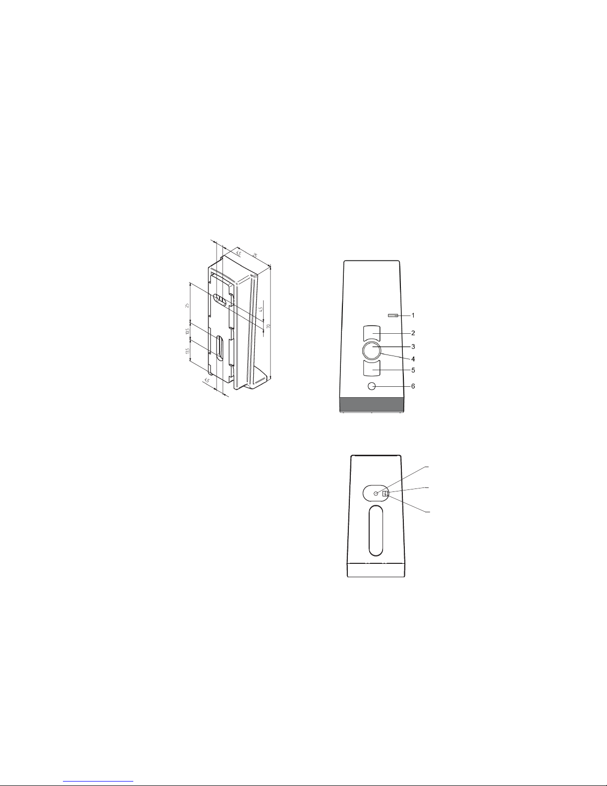
• Make sure that the holes are not
drilled into electric cables when
fi tting the wall bracket.
• Before installing the unit in the
required position, check that
the transmitter and receiver are
functioning perfectly.
• Attach the bracket to the wall
with the wall plugs and screws
provided.
The top part of the wall bracket can
be moved.
Description of the device
Front side of the device
1 Operating mode indicator
2 UP button
3 STOP button
4 Status indicator
5 DOWN button
6 Select button
Rear of the device
7
8
9
7 Programming button P
Only for experts:
8 DIP switch 1
9 DIP switch 2
M
ounting of wall bracke
t
D
escription of the devic
e
Page 5

© weinor GmbH & Co. KG 8 | EN © weinor GmbH & Co. KG EN | 9
Explanation of functions
Bidirectional radio system
A bidirectional radio system transmits radio signals to a radio
receiver and enables feedback from the radio receiver to the
transmitter. The radio signal can be sent directly to the target
receiver. If this is not possible then the radio signal is forwarded
via other bidirectional nodes until the signal reaches the target
receiver. The target receiver carries out the command and sends a
confi rmation back to the transmitter.
Bidirectional radio operation is only possible if all nodes are
bidirectional. Otherwise, the system is only unidirectional.
Initial operation
Pressing a button switches on the handheld transmitter and lights
the status display and operating mode display. The handheld
transmitter is in automatic mode when fi rst switched on.
Note
Do not press the P button until the receivers are in
programming mode. The active channel selects a radio system
during programming. If the receivers are not in programming
mode, the transmitter channel changes to unidirectional mode.
Press the STOP and P buttons simultaneously for 6 seconds
until the status display lights to restore the initial condition.
Status display
A radio signal is indicated by the status display (LED ring around
the STOP button) lighting up. The various colours of the status
display mean:
Status display Meaning
Flashing orange Channel (transmitter) not programmed in any
receiver
Flashing orange
rapidly
Channel (transmitter) in bidirectional programming mode. Operation of already programmed
receivers is not possible.
Every 3 seconds in group programming mode
(even if no button is pressed)
Orange then green Channel (transmitter) is operating bidirectionally
and receiver has received the signal
Orange then fl ashing
red
Channel (transmitter) is operating bidirectionally
and one of the receivers has not received the
signal
Red then green Channel (transmitter) is operating bidirectionally
and receiver has received the signal, batteries
weak
Red then fl ashing red Channel (transmitter) is operating bidirectionally
and one of the receivers has not received the
signal, batteries weak
Alternating orange
and green (or red),
then red (bidirectional)
Channel (transmitter) is deleted
Flashing red Batteries weak
The transmitting power or radio range will be reduced by declining
battery output. No more functions are executed and there is no
display if the voltage drops below 2 V.
Group control unit
A group is understood to mean the control of several receivers
at the same time. The selected group is controlled by a travel
command.
Any number of receivers can be programmed and controlled in the
channel.
Exp
lanation of functions
Exp
lanation of functions
Page 6

© weinor GmbH & Co. KG 10 | EN © weinor GmbH & Co. KG EN | 11
Selection button
Pressing the selection button briefl y allows you to query the
current mode (automatic/manual) of the programmed receivers
(bidirectional receivers only) and the handheld transmitter channel.
Pressing and holding (for approximately 1 second) the selection
button switches automatic mode off. The operating mode indicator
lights up red. → The receiver now only carries out manual travel
commands and does not respond to automatic travel commands.
Note
Upward travel of the receiver is initiated when the automatic
system is activated.
Pressing and holding (for approximately 1 second) the selection
button switches automatic mode back on. The operating mode
indicator lights up green. → The receivers now execute automatic
and manual travel commands.
Programming the transmitter
Requirement
The receiver is installed. Check whether the channel has been
deleted.
Stand in front of the curtain to be programmed while programming.
1. Where electrical receivers have already been installed, switch
the circuit breaker off and on again after a few seconds.
The receiver is now in programming mode for about 5 minutes.
2. Press the programming button P on the rear of the device briefl y
(approximately 1 second) until the status display lights up briefl y.
The curtain moves up and down for approximately two minutes,
showing that the receiver is in programming mode.
3. Press the UP button as soon as the curtain starts moving in
Open direction (within 1 second at the most). The status display
lights briefl y.
The curtain stops briefl y, travels further, stops and then travels in
the downwards direction.
4. Immediately (no more than 1 second) the curtain starts moving
downwards, press the DOWN button. The status display
lights up briefl y. The curtain stops. The transmitter channel is
programmed.
Note
Programming will have to be repeated if the curtain does not
stop.
A bidirectional programming process in the handheld
transmitter can be cancelled by pressing the STOP button for
6 seconds.
Programming additional transmitters
Note
Where multiple receivers are connected to the same
supply, they are all simultaneously ready for programming for
approximately 5 minutes after connection to the mains.
If the P button is now pressed on the transmitter, all receivers
start the programming mode simultaneously (ascents/
descents). An offset is created between the receivers by
randomly different pauses between the ascentsdescents. The
longer programming is delayed, the greater the offset will be.
The brief ascents/descents can be stopped by pressing the
STOP button briefl y on a transmitter that has already been
programmed. The programming mode in the receiver is
interrupted.
The transmitter can now be assigned without having to
disconnect individual receivers. If the curtain moves in the
wrong direction, delete the transmitter and program it again.
(→ see Deletion of transmitter)
To program additional transmitters to one receiver:
1. Press the UP, DOWN and programming P (rear of the device)
buttons simultaneously (for three seconds) on a transmitter
that has already been programmed to the receiver. The status
Exp
lanation of functions
Exp
lanation of functions
Page 7

© weinor GmbH & Co. KG 12 | EN © weinor GmbH & Co. KG EN | 13
display lights up briefl y. The receiver is now in programming
mode.
2. Press the programming button P on the transmitter to be
programmed until the status display lights briefl y. The receiver is
now in programming mode (ascents/descents).
3. Press the UP button immediately (within no more than 1 second)
the curtain starts moving upwards. The status display lights up
briefl y. The curtain stops briefl y, starts moving again and then
moves downwards.
4. Immediately (no more than 1 second) the curtain starts moving
downwards, press the DOWN button. The status display
lights up briefl y. The curtain stops. The transmitter channel is
programmed.
If more than 10 bidirectional receivers are being programmed in one
channel at the same time, the transmitter channel in programming
mode switches to group mode. Group mode is indicated by fast
fl ashing with pauses.
Programming in group mode is completed after a 2-minute pause or
pressing the STOP button for 6 seconds.
Note
A jogging mode for Venetian blinds for quickly reaching
receivers which are further away is not possible in a
bidirectional transmitter channel with more than 10
programmed receivers.
Synchronized programming mode
For programming one transmitter to multiple receivers at the same
time.
1. Press the DOWN and programming P (rear of the device)
buttons simultaneously (for 3 seconds) on a transmitter that has
already been programmed to the receivers. The status display
fl ashes. The receivers are now in programming mode.
2. Press the programming button P on the transmitter to be
programmed until the status display lights up briefl y. The
receivers are now in programming mode (ascents/descents).
3. Press the UP button immediately (within no more than 1 second)
the curtain starts moving upwards. The status display lights up
briefl y. The curtains stop briefl y, start moving again, stop and
then move downwards.
4. Immediately (no more than 1 second) the curtain starts moving
downwards, press the DOWN button. The status display lights
up briefl y. The curtains stop moving. The transmitter channel is
programmed.
Stopping programming mode in the transmitter
Press the STOP button and hold for at least 6 seconds until the
status display lights up orange.
Approaching end positions of roller shutter /
awning / Venetian blind
Requirement
The transmitter/transmitter channel is programmed. The end
positions of the drive have been set.
Approaching the lower end position (roller blind/awning)
Press the DOWN button briefl y. The curtain descends to the lower
end position/the awning extends fully.
Approaching the lower end position (blind)
Press the DOWN button until the status display lights briefl y. The
blind approaches the lower end position.
Press the DOWN button only briefl y (jog mode on JA, pulse mode
for Combio Pulse), the blind approaches briefl y and stops again.
Exp
lanation of functions
Exp
lanation of functions
Page 8
© weinor GmbH & Co. KG 14 | EN © weinor GmbH & Co. KG EN | 15
Approaching the upper end position (roller blind/awning)
Press the UP button briefl y. The blind approaches the upper end
position/the awning retracts.
Approaching the upper end position (blind)
Press the UP button until the status display lights briefl y. The blind
approaches the upper end position.
Press the UP button only briefl y (jog mode on JA, pulse mode for
Combio Pulse), the blind approaches briefl y and stops again.
Intermediate positions of the blinds
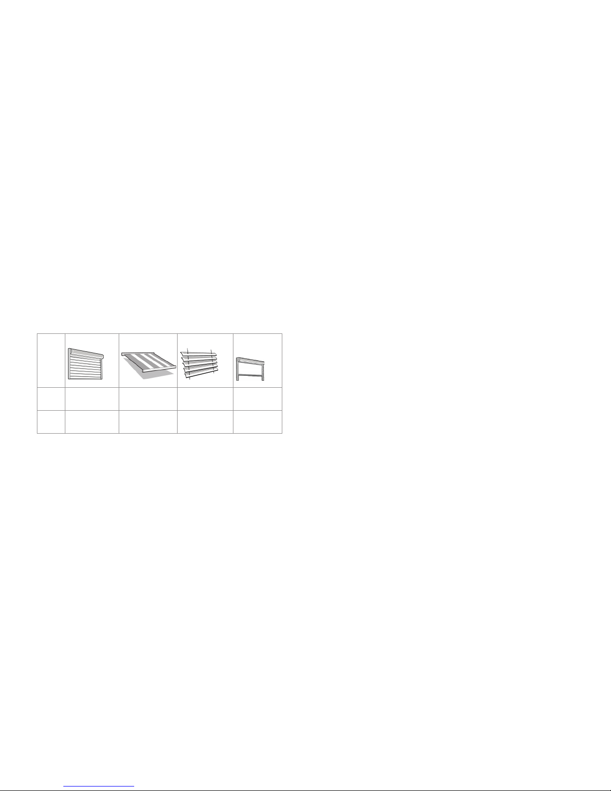
Roller shutter Awning Venetian blind Interior
shading
Pos▼ Intermediate
position
Intermediate
position
Intermediate
position
Intermediate
position 1
Pos▲ Ventilation
position
-- /fabric tensioning
Turning
position
Intermediate
position 2
Programming the intermediate position in the receiver
Requirement
The transmitter/transmitter channel is programmed. The end
positions of the drive have been set. The blind is in the upper end
position.
1. Move the blind to the desired position with the DOWN button.
Press and hold the DOWN button to do this.
2. Also press the STOP button. The blind stops. The status display
lights up briefl y.
The intermediate position is programmed.
Programming the ventilation/turning position in the receiver
Requirement
The transmitter/transmitter channel is programmed. The end
positions of the drive have been set. The blind is in the lower end
position.
1. Move the blind in the UP direction using the UP button until the
ventilation slots open, or the slats have turned. Keep the UP
button pressed during the movement.
2. Also press the STOP button. The blind stops. The status display
lights up briefl y.
The ventilation/turning position is programmed.
Approaching the intermediate position
Requirement
The transmitter/transmitter channel is programmed. The curtain is at
its upper end position.
1. Press the DOWN button twice briefl y. The status display lights
up briefl y.
2. The curtain travels to the stored intermediate position. In the
case of Venetian blinds, the slats turn automatically after
reaching the intermediate position if a turning position has been
programmed. If no intermediate position is programmed, the
curtain travels to the lower end position (not if Combio Pulse is
in use).
Approaching the ventilation/turning position
Requirement
The transmitter/transmitter channel is programmed. The blind is at
its lower end position.
1. Press the UP button twice briefl y. The status display lights up
briefl y.
Exp
lanation of functions
Exp
lanation of functions
Page 9
© weinor GmbH & Co. KG 16 | EN © weinor GmbH & Co. KG EN | 17
2. The blind travels to the save ventilation/turning position. If no
ventilation/turning position is programmed, the blind travels to
the upper end position (not if Combio Pulse is in use).
Operation of the transmitter using Combio JA
Pulse
A Combio 868/915 JA Pulse can be used for the precise adjustment
of the slats for Venetian blind drives.
The preset pulse time of Combio Pulse is cycled by pressing the UP
or DOWN button.
The pulse time can be changed by the user. Keep the STOP and
UP buttons on a programmed transmitter pressed for 6 seconds
for this. The drive starts to move in small pulses. As soon as the
blind has travelled the required distance, release the UP button,
then release the STOP button. The new pulse time is saved. The
new pulse time corresponds to the sum of all pulse times during
the programming of the pulse time. The Combio JA Pulse ends the
programming of the pulse time after 30 pulses.
Deleting positions/deleting transmitters
Deleting the intermediate position from the receiver
1. Press the STOP button and also the DOWN button.
2. Hold this button combination for approximately three seconds.
The status display lights up briefl y.
Deleting the ventilation/turning position from the receiver
1. Press both the STOP button and the UP button.
2. Hold this button combination for approximately three seconds.
The status display lights up briefl y.
Deleting the transmitter channel from the receiver
1. Press the STOP button and also the programming button P (on
the rear of the device).
2. Keep this button combination pressed for approximately 6
seconds until the status display lights orange briefl y and then
lights red.
The channel in the transmitter is also deleted.
Deleting all transmitters from the receiver
1. Press the STOP button and also the programming button P (on
the rear of the device) + UP button + DOWN button.
2. Hold this button combination for approximately six seconds.
The status display lights orange/green briefl y twice, followed by
red (bidirectional).
The channel in the transmitter is also deleted.
Expert settings
DIP switch 2 on the rear of the device, beneath the cover:
switch up: OFF (bidirectional and unidirectional operation possible,
preset), switch down: ON (only bidirectional operation is possible).
DIP switch 1: OEM setting.
Replacing the battery
Note
Replace batteries only with batteries of
identical type.
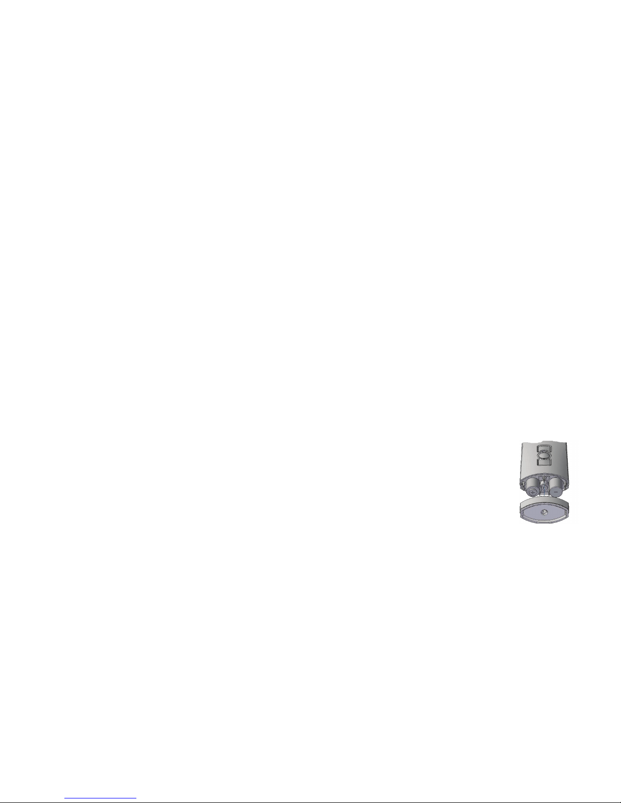
1. Unscrew the underside of the device and
open the housing.
2. Remove the batteries.
3. Insert the new batteries in the correct
position.
4. Reassemble the device.
Dispose of used batteries properly.
Exp
lanation of functions Replacing the batter
y
Page 10

© weinor GmbH & Co. KG 18 | EN © weinor GmbH & Co. KG EN | 19
Cleaning
Clean the device with a damp cloth. Do not use a detergent. This
may attack the plastic.
Disposal
Dispose of the device in accordance with the relevant regulations
when you no longer need it.
Troubleshooting
Fault Cause Remedy
Drive not running,
status display does
not light up
1. Batteries are
exhausted
2. Batteries are incorrectly installed
1. Insert new batteries
2. Insert batteries
correctly
Drive not running,
status display fl ashes
red or orange
1. Receiver out of
radio range
2. Receiver not operating or faulty
3. Receiver not yet
programmed
1. Reduce distance to
the receiver
2. Switch on or replace receiver
3. Program receiver
Drive runs in the
wrong direction
Directions are incorrectly allocated
Delete transmitter and
reprogram
Repair
Please contact your dealer if you have any questions.
Please always provide the following information:
• Item number and name on the type plate
• Type of fault
• Unusual events occurring prior to fault
• Accompanying conditions
• Own suspicion
Cleanin
g
Repair
Page 11

© weinor GmbH & Co. KG 20 | EN © weinor GmbH & Co. KG EN | 21
EC Declaration of conformity
Hersteller:
weinor GmbH & Co. KG
Mathias-Brüggen-Straße 110
50829 Köln, Deutschland
Bevollmächtigte Person für die Zusammenstellung der technischen Unterlagen:
Mücke, Frank, Dokumentationsbevollmächtigter
weinor GmbH & Co. KG
Mathias-Brüggen-Str. 110
50829 Köln, Deutschland
Hiermit erklären wir,
dass der nachfolgend bezeichnete Funksender aufgrund seiner Konzipierung und Bauart,
sowie in der von uns in Verkehr gebrachten Ausführung den einschlägigen grundlegenden
Sicherheits- und Gesundheitsanforderungen der folgenden EU-Richtlinien entsprechen.
Bei einer nicht von uns abgesprochenen Änderung des Funksenders verliert die Erklärung ihre
Gültigkeit.
x EU-Niederspannungsrichtlinie (2006/95/EG)
x EU-Richtlinie über elektromagnetische Verträglichkeit (2004/108/EG)
x R&TTE-Richtlinie 1999/5/EG
x RoHS-Richtlinie 2002/95/EG
Produktbezeichnung: Funksender BiEasy 1M
Produktbeschreibung: Funksender für bidirektionale Kommunikation zwischen Sender
und Empfänger zur Steuerung von Markisen und LED-Beleuchtung
Baujahr: 2013
Die elektrischen Kenndaten des Funksenders befinden sich auf dem Typenschild und den
Dokumentationsunterlagen des Funksenders.
Datum / Herstellerunterschrift:
Köln, 04.03.2013 ppa. Karl-Heinz Stawski
Address
weinor GmbH & Co. KG
Mathias-Brüggen-Straße 110
50829 Köln
Deutschland / Germany
Tel: +49 221 5 97 09-211
Fax: +49 221 5 97 09-898
[email protected]
www.weinor.de
Please visit our webpage
should you need a contact
person outside Germany.
E
C Declaration of conformit
y
Address
Page 12

© weinor GmbH & Co. KG 22 | EN © weinor GmbH & Co. KG EN | 23
E
C Declaration of conformit
y
E
C Declaration of conformit
y
Page 13

© weinor GMbH & Co. KG
 Loading...