

Page 1
Zone
Controller
Instruction manual
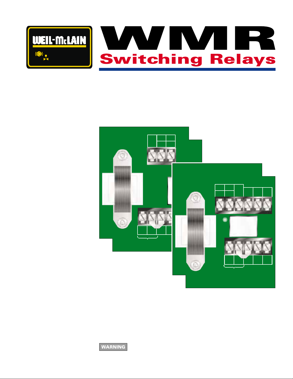
• WMR-21 DPST (Double-pole/single throw)
• WMR-22 DPDT (Double-pole/double throw)
WMR-21
Switching Relay
Weil-McLain
Michigan City, IN
24V
L2 L1
120 VAC
T
T
RC
W
Made in U.S.A.
Circuit ON
WMR-22
Switching Relay
W
24V
T
T
RC
3
5
4
6
Circuit ON
L2 L1
120 VAC
5
3
NONONC
6
6
4
4
NC
Made in U.S.A.
85902
Weil-McLain
Michigan City, IN
This manual must only be used by a qualified heating installer/service
technician. Failure to comply could result in severe personal injury, death
or substantial property damage.
Part Number 550-141-859/0799
Page 2
WMR Switching Relays
Contents Hazard definitions and “To the installer” .............................................................. 2
Specifications and replacement parts ................................................................... 2
WMR-21 layout, schematic diagram and cross reference table ......................... 3
WMR-22 layout, schematic diagram and cross reference table ......................... 3
WMR-21 and WMR-22 General wiring .................................................................. 4
WMR-21 Typical application wiring ..................................................................... 4
Hazard definitions
To the installer
Indicates presence of hazards that will cause severe personal injury, death
or substantial property damage.
Indicates presence of hazards that can cause severe personal injury, death
or substantial property damage.
Indicates presence of hazards that will or can cause minor personal injury
or property damage.
Indicates special instructions on installation, operation or maintenance that
are important but not related to personal injury or property damage.
Electrical shock hazard — Disconnect power before installing or servicing.
Can cause severe personal injury, death or substantial property damage if
ignored.
To avoid severe personal injury, death or substantial property damage, never
connect the load terminals to a load that takes more current than the amount
listed for the relay in the electrical ratings.
Use copper wire only. Use of any other type of wire could cause a fire hazard
resulting in severe personal injury, death or substantial property damage.
All wiring must be installed in accordance with:
U.S.A. — National Electrical Code and any other national, state or local
code requirements. Wiring must be N.E.C. Class 1.
Canada — C.S.A. C22.1 Canadian Electrical Code Part 1 and any other
national, provincial or local code requirements. Wiring must be C.S.A.
C22.1 C.E.C. Part 1.
Specifications
Replacement parts
2
Weil-McLain
model
number
WMR-21 120 V 60 HZ
WMR-22 120 V 60 HZ
Part description Weil-McLain part number
Plug-in relay (24 VAC coil) 510-311-021
Transformer
voltage
15 VA
15 VA
Switching
action
DPST .18 10 A,
DPDT .18 10 A,
Thermostat
current
amps
120 VAC 240 VAC
Part Number 550-141-859/0799
Single-phase motor
rating
10 A,
¹⁄₃ HP
¹⁄₃ HP
¹⁄₂ HP
10 A,
¹⁄₂ HP
Page 3
Instruction manual
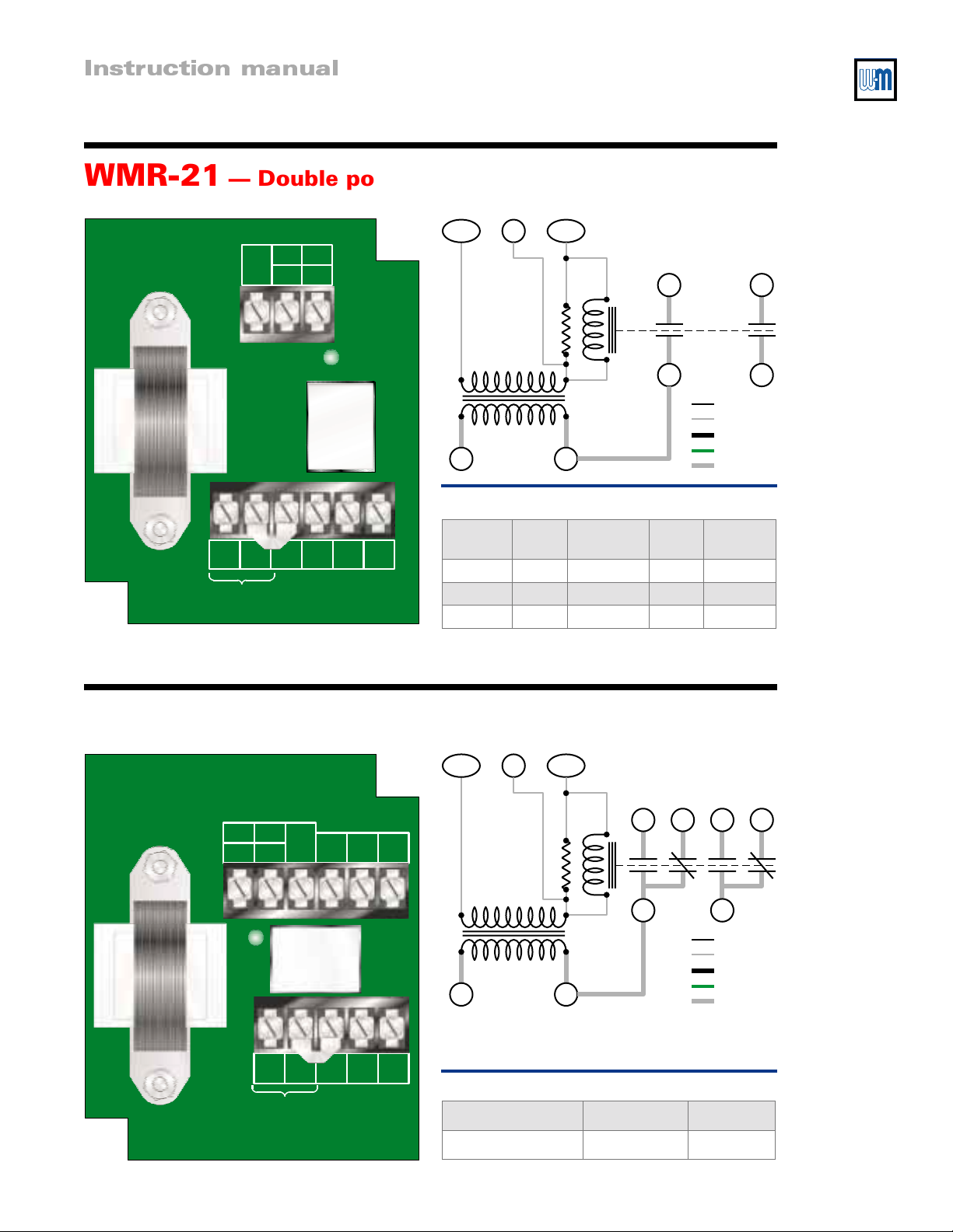
WMR-21 — Double pole/single throw switching relay
WMR-21
Switching Relay
Weil-McLain
Michigan City, IN
24V
L2 L1
120 VAC
T/W
T
T
RC
W
T/R
C
46
85903
Relay coil
Made in U.S.A.
Circuit ON
24 VAC
120 VAC
L2 L1
3
Jumper
5
24 VAC field wiring
24 VAC factory wiring
120 VAC field wiring
120 VAC ground lead
120 VAC factory wiring
WMR-21 cross reference table
Weil-
3
5
4
6
McLain
WMR-21 AR821 RA 89A SR501 809A-189
WMR-21 AR821 RA 832A SR501 829A-832
WMR-21 AR821 R 845A SR501 829A-845
Argo Honeywell Taco White-
Rodgers
WMR-22 — Double pole/double throw switching relay
85902
WMR-22
Switching Relay
Weil-McLain
Michigan City, IN
T
RC
Circuit ON
24V
T
W
L2 L1
120 VAC
5
3
NONONC
6
6
4
4
NC
Made in U.S.A.
T/W
24 VAC
120 VAC
L2 L1
WMR-22 cross reference table
Weil-McLain Argo Taco
WMR-22 AR822 SR501
T/R
C
NO NC NO NC
4646
Relay coil
3
Jumper
5
24 VAC field wiring
24 VAC factory wiring
120 VAC field wiring
120 VAC ground lead
120 VAC factory wiring
85904
Part Number 550-141-859/0799
3
Page 4
WMR Switching Relays
Electrical shock hazard —
Disconnect power before
installing or servicing. Can
cause severe personal injury,
death or substantial property
damage if ignored.
All wiring must be installed in
accordance with:
U.S.A. — National Electrical
Code and any other
national, state or local code
requirements. Wiring must
be N.E.C. Class 1.
Canada — C.S.A. C22.1
Canadian Electrical Code
Part 1 and any other
national, provincial or local
code requirements. Wiring
must be C.S.A. C22.1 C.E.C.
Part 1.
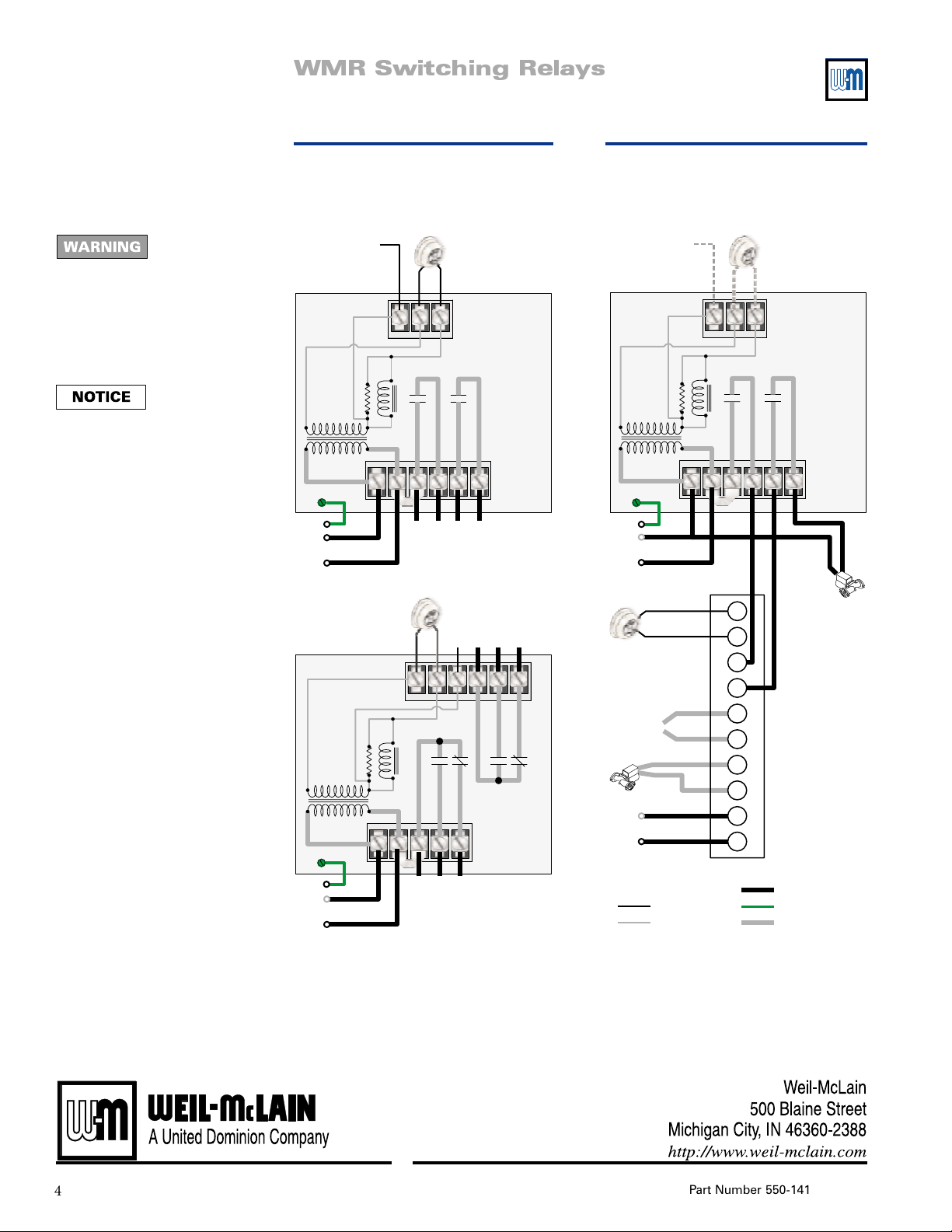
WMR-21 and WMR-22
General wiring
24 vac to 3-wire
thermostat
WMR-21
Ground
screw
Ground
Neutral
120 VAC
Hot
WMR-22
Ground
screw
Ground
Neutral
120 VAC
Hot
24 VAC
120 VAC
24 VAC
120 VAC
Thermostat or
isolated contact
to activate relay
TRT
C
W
L2
L1
4
3
contact out
Normally open
TRT
W
L2
L1
3
4
NO
Common
Normally open
Thermostat or
isolated contact
to activate relay
Remove factoryinstalled jumper from
L1 to 3 to use 3–4
as isolated contacts.
5
6
contact out
Normally open
24 vac to 3-wire
thermostat
Common
C
5
Remove factoryinstalled jumper from
4
L1 to 3 to use 3/4/4
NC
as isolated contacts.
Normally closed
6
NO
Normally closed
Normally open
6
NC
85905
85906
WMR-21 — Typical application
Add circulator to L8124A or C
aquastat/relay
TRT
3
T
T
ZR
ZC
B1
B2
C1
C2
1
2
Thermostat or
isolated contact
to activate relay
W
4
5
L8124A or C
Aquastat/relay
120 VAC field wiring
120 VAC ground lead24 VAC field wiring
120 VAC factory wiring
6
24 vac to 3-wire
WMR-21
24 VAC
120 VAC
Ground
screw
Ground
Neutral
120 VAC
Hot
To burner control
Circulator 1
Neutral
120 VAC
Hot
Legend
thermostat
C
L2
L1
24 VAC factory wiring
Circulator 2
85907
4
Part Number 550-141-859/0799
 Loading...