

Page 1
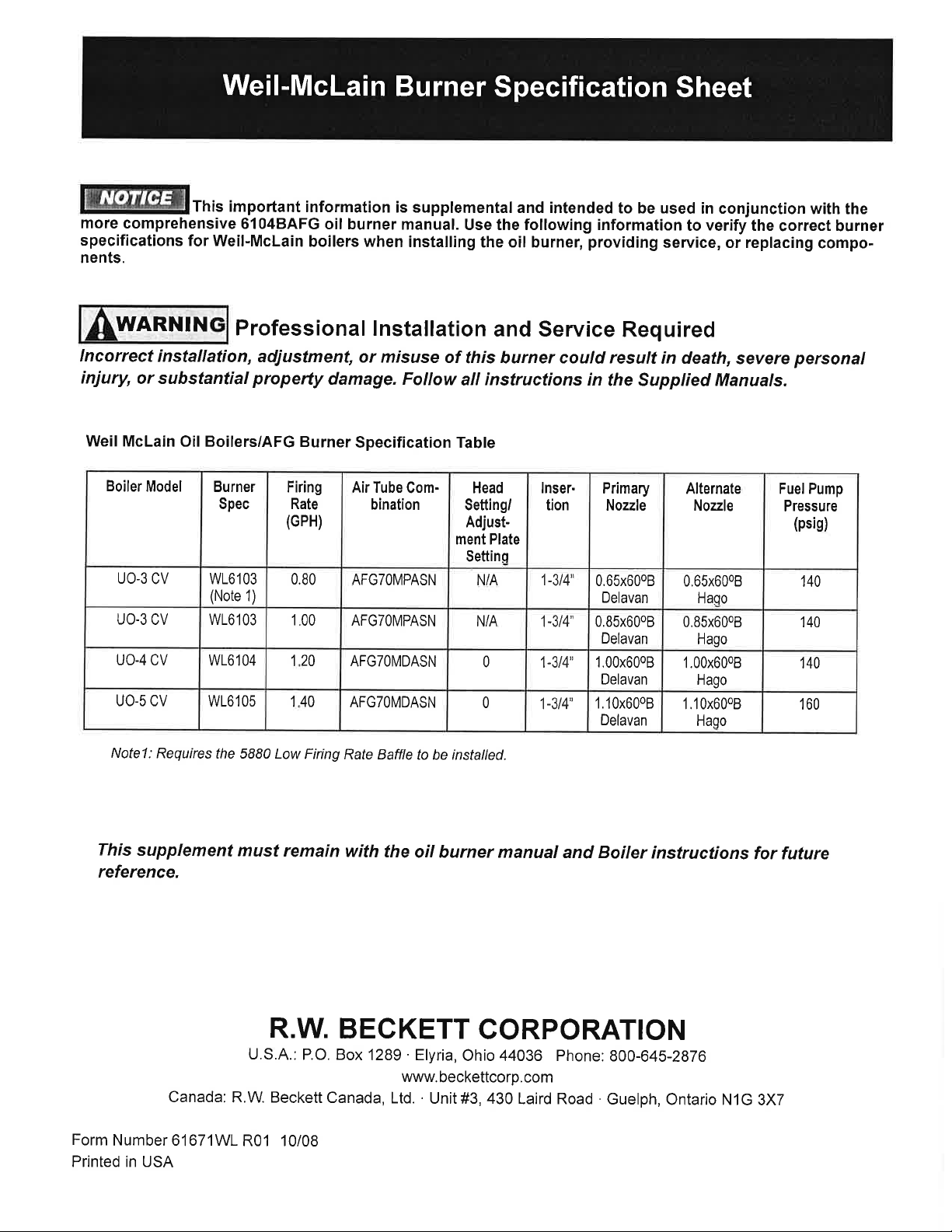
R02 01/09
Page 2
AF/AFG
AF/AFG
Oil Burner Manual
Oil Burner Manual
RESIDENTIAL BURNERS
Potential for Fire, Smoke and Asphyxiation Hazards
Incorrect installation, adjustment, or misuse of this burner could result in death, severe personal
injury, or substantial property damage.
To the Homeowner or Equipment Owner:
Please read and carefully follow all instructions
y
provided in this manual regarding your
responsibilities in caring for your heating
equipment.
Contact a professional, qualifi ed service agency
y
for installation, start-up or service work.
Save this manual for future reference.
y
6104BAFG R05 Page 1
To the Professional, Qualif ed Installer or
Service Agency:
Please read and carefully follow all instructions
y
provided in this manual before installing,
starting, or servicing this burner or heating
system.
The Installation must be made in accordance
y
with all state and local codes having jurisdiction.
Page 3

Table of Contents
Hazard Def nitions and Owner’s Information ........................................................................................3
Information To Be Used Only By Qualif ed Service Technicians
General Information .........................................................................................................................................4
Table 1 Burner Specifi cation ................................................................................................................................4
Notice Special Requirements ..............................................................................................................................5
Table 2 Air Tube Combination (ATC) Codes ………………………………………………………….. .....................5
Inspect/Prepare Installation Site .................................................................................................................6
Inspect Chimney or Direct Vent System ..............................................................................................................6
Combustion Air Supply ........................................................................................................................................7
Clearances to burner and appliance ...................................................................................................................7
Combustion chamber - Burner Retrofi tting ..........................................................................................................7
Prepare the Burner ...........................................................................................................................................8
Low Firing Rate Baffl e ............................................................................................................................ .............8
Burner Fuel Unit ..................................................................................................................................................8
Attach Air Tube ....................................................................................................................................................8
Nozzle and Pump Pressure .................................................................................................................................8
Install Burner Nozzle ...........................................................................................................................................8
Check/Adjust Electrodes .....................................................................................................................................9
Servicing nozzle line assembly ...........................................................................................................................9
Check/Adjust ‘Z’ Dimension - F Heads .............................................................................................................10
Check/Adjust ‘Z’ Dimension - L & V Heads .......................................................................................................11
Mount burner on appliance ...........................................................................................................................9
Mounting Options ................................................................................................................................................9
Mounting Dimensions ..........................................................................................................................................9
Installing the Oil Tank & Supply System ............................................................................................................12
Fuel Line Valves & Filter ....................................................................................................................................12
Wire Burner .......................................................................................................................................................13
Burner Packaged with Appliance .......................................................................................................................13
Burner Installed at Job Site ...............................................................................................................................13
Special Wiring Required with Covered Burners ................................................................................................13
Burner Control .................................................................................................................................................14
GeniSys Model 7505 Control ............................................................................................................................14
Wiring ................................................................................................................................................................14
Typical Burner Sequence of Operation for GeniSys 7505 Control ....................................................................15
Typical Burner Sequence of Operation for R7184P Control ..............................................................................17
Start-up Burner/Set Combustion ..............................................................................................................18
Startup/checkout ...............................................................................................................................................19
Set Combustion with Instruments ......................................................................................................................19
Perform Regular Maintenance ...................................................................................................................20
Parts Diagram ...................................................................................................................................................22
Beckett Limited Warranty Information ...................................................................................................24
Page 2 6104BAFG R06
Page 4
Hazard Defi nitions
!
!
General Information
!
DANGER
Indicates a hazardous situ-
ation, which, if not avoided,
will result in death or serious injury.
!
WARNING
Indicates a hazardous
situation, which, if not
avoided, could result in death or serious
injury.
!
CAUTION
Indicates a hazardous
situation, which, if not
avoided, could result in minor or moderate
injury.
Within the boundaries of the hazard warning, there will
be information presented describing consequences if the
warning is not heeded and instructions on how to avoid
the hazard.
NOTICE
information, but not related to personal injury or property
damage.
Intended to bring special attention to
WARNING
!
Incorrect installation, adjustment,
and use of this burner could result in
severe personal injury, death, or substantial property damage from fi re,
carbon monoxide poisoning, soot or explosion.
Contact a professional, qualifi ed service agency for the
installation, adjustment and service of your oil heating
system. This work requires technical training, trade experience, licensing or certifi cation in some states and the
proper use of special combustion test instruments.
Please carefully read and comply with the following
instructions:
Never store or use gasoline or other fl ammable
y
liquids or vapors near this burner or appliance.
Never attempt to burn garbage or refuse in this
y
appliance.
Never attempt to light the burner/appliance by
y
throwing burning material into the appliance.
Never attempt to burn any fuel not specifi ed and
y
approved for use in this burner.
Never restrict the air inlet openings to the burner
y
or the combustion air ventilation openings in the
room.
Owner’s Responsibility
NOTICE
appear to be basically identical, but there are differences in design and performance. Please review the comparison
chart below:
Feature AF AFG
Static Pressure Capability Conventional - Low range Enhanced - Medium range
Blower Wheel Design Standard strip Special tablock
Inlet Airfl ow Design Standard inlet bell Special airguide
UL Air Tube Combinations “F” Series ONLY “F” or “M” Series
Igniter Gaskets Baseplate/Barrier Optional, as specifi ed Required, always specifi ed
Low Firing Rate Baffl e Not required Required, per specifi cation
This manual contains information that applies to both AF and AFG burners. These burners may
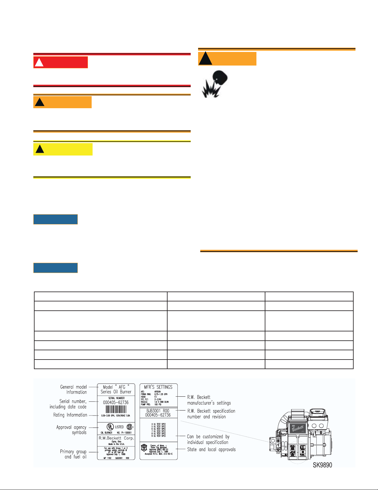
Figure 1. Burner label location
6104BAFG R06 Page 3
Page 5
General Information
To the Owner:
Thank you for purchasing a Beckett burner
for use with your heating appliance. Please pay attention to the Safety Warnings contained within this
instruction manual. Keep this manual for your records
and provide it to your qualifi ed service agency for use
in professionally setting up and maintaining your oil
burner.
Your Beckett burner will provide years of effi cient op-
eration if it is professionally installed and maintained
by a qualifi ed service technician. If at any time the
burner does not appear to be operating properly, im-
mediately contact your quali f ed service agency
for consultation.
We recommend annual inspection/service of your
oil heating system by a qualif ed service agency.
Daily – Check the room in which your burner/appli-
ance is installed. Make sure:
Air ventilation openings are clean and unobstruct-
•
ed
Nothing is blocking burner inlet air openings
•
No combustible materials are stored near the heat-
•
ing appliance
There are no signs of oil or water leaking around
•
the burner or appliance
Weekly
Check your oil tank level. Always keep your oil tank
•
full, especially during the summer, in order to prevent condensation of moisture on the inside surface
of the tank.
!
WARNING
Impaired Burner Perfor-
mance and Fire Hazard.
Do NOT operate the burner beyond specif ca-
tions outlined in the following Table.
For applications beyond these limits, consult
y
Beckett Technical Service at 1-800-645-2876.
NOTE: Some packaged appliances with burners
y
may be agency listed as a unit to operate beyond
these limits. Consult the appliance manufacturer’s specifi cations and agency approvals for
verifi cation.
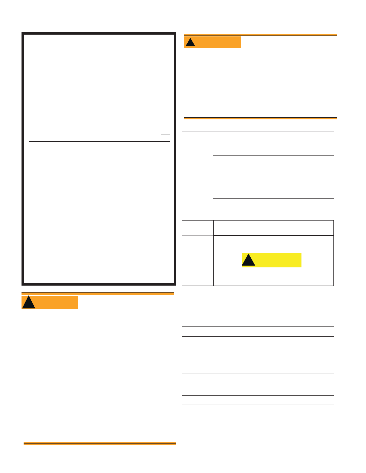
Table 1 – Burner Specif cations
Capacity
(Note 1)
Certifi cations/
Approvals
Fuels U. S No. 1 or No. 2 heating oil only (ASTM D396)
‘F’ Head (AF & AFG)
Firing rate range: ..............0.40 – 3.00 GPH
Input: ....................... 56,000 – 420,000 Btu
‘L1’ Head (AFG Only)
Firing rate range: ..................0.40 - 1.10 GPH
Input: .....................56,000 – 154,000 Btu/h
‘L2’ Head (AFG Only)
Firing rate range: .................0.50 - 1.00 GPH
Input: ......................70,000 – 140,000 Btu/h
‘V1’ Head (AFG Only)
Firing rate range: .................0.75 - 2.75 GPH
Input: ....................105,000 – 385,000 Btu/h
UL listed to comply with ANSI/UL296 and CSA-B140.0
Canada No. 1 stove oil or No. 2 furnace oil only
CAUTION
!!
DO NOT USE GASOLINE, CRANKCASE OIL,
OR ANY OIL CONTAINING GASOLINE.
Electrical Power supply:............ 120 volts AC, 60 Hz single phase
WARNING
!
Do NOT Alter the Original
Burner Design
Tampering with or altering the burner design
could seriously impair performance, resulting
in loss of static pressure, damage to the system
components, reduced air volume, heavy smoke,
fl ame impingement, appliance sooting, hot gas
puff-back, and asphyxiation or fi re hazards.
Maintain the design to its original confi guration.
Only use parts specifi ed for AF or AFG Burners
Do NOT remove the air guide from the AFG chassis.
Do NOT use ‘M’ Series air tube combinations on AF Burn-
ers.
Never try to convert an AF to an AFG or vice versa
Any design alteration will:
Void UL Listing
y
Void manufacturer’s warranties
y
Seriously impact burner performance
y
Greatly increase your liability risk
y
Page 4 6104BAFG R06
Fuel pump
Air tube ATC code: ...................................See Table 2
Dimensions
(with cover)
Ambient
Operating
Temperature
Moisture 5% to 95% RH, non-condensing and non-crystallizing
Operating load: .......... Amps max
Motor: .........................1/7 hp, 3450 rpm, NEMA 48M frame
PSC rotation CCW when facing
shaft end
Ignition: ......................Continuous duty solid-state igniter
Outlet pressure: ..................................Note 2
Height (maximum) .......................12.5 inches
Width (maximum) ..........................15 inches
Depth .........................................9.25 inches
Air tube diameter ....................... 4.00 inches
+32o F. (0 C.) Minimum
+115o F. (+46 C.) Maximum
(See above Warning)
Note 1: Approval agency listed rating for these burners is 0.40 to 3.00
gph. However, the fi ring rate range is limited by the specifi c
air tube combination being used. Refer to Table 2.
Note 2. See appliance manufacturer ’s burner specifi cations for rec-
ommended pump discharge pressure.
Page 6
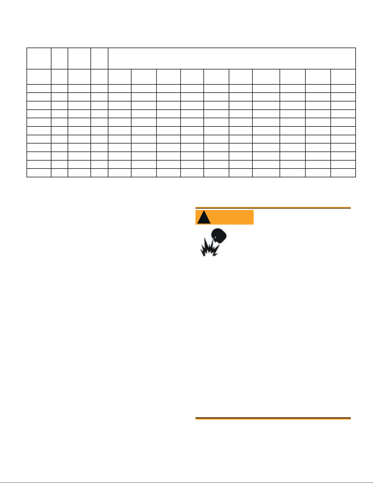
General Specifi cations
Table 2 – Air Tube Combination (ATC) codes
Firing
Rate
(gph)
(min-
max)
0.50-0.75 F0 3-3/8U None AF44XR - AF53XR AF65XR - AF72XR AF90XR AF104XR AF130XR A160XR
0.75-1.25 F3 2-3/4U None AF44XN - AF53XN AF65XN - AF72XN AF90XN AF104XN AF130XN AF160XN
0.85-1.35 F4 2-3/4U None AF44WH - AF53WH AF65WH - AF72WH AF90WH AF104WH AF130WH AF160WH
0.85-1.65 F6 2-3/4U None AF44YB - AF53YB AF65YB - AF72YB AF90YB AF104YB AF130YB AF160YB
1.10-2.00 F12 2-3/4U None AF44XO - AF53XO AF65XO - AF72XO AF90XO AF104XO AF130XO AF160XO
1.65-2.50 F22 2-3/4U None AF44XP - AF53XP AF56XP - AF72XP AF90XP AF104XP AF130XP AF160XP
2.50-3.00 F31 None None AF44XS - AF53XS AF65XS - AF72XS AF90XS AF104XS AF130XS AF160XS
0.50-1.10 L1 3-3/8U 8hole - AFG50MB - - AFG70MB - AFG90MB - - -
0.50-1.00 L2 2-3/4U 8hole AFG50MP - - AFG70MP - AFG90MP - - -
0.75-2.75 V1 2-3/4U 8hole - AFG50MD - - AFG70MD - AFG90MD - - -
0.40-0.75 F0 3-1/2U None AF44WG - AF53WG AF65WG - AF72WG AF90WG AF104WG AF130WG A160WG
Head Static
plate
size
(inches) 4-1/2 5 5-3/8 6-5/8 7 7-1/4 9 10-1/2 13 16
Ven-
turi
ATC Codes for usable air tube lengths
(‘A’ in inches; See Figure 3.)
Notice Special Requirements
THE INSTALLATION OF A BURNER SHALL BE
y
IN ACCORDANCE WITH THE REGULATIONS
OF AUTHORITIES HAVING JURISDICTION.
For recommended installation practices in the
y
U.S. refer to the latest edition of NFPA 31. (CSAB139 and CSA-B140 in Canada.
Concealed damage — If you discover damage to
y
the burner or controls during unpacking, notify the
carrier at once and fi le the appropriate claim.
When contacting Beckett for service information
y
— Please record the burner serial number (and
have available when calling or writing). You will
fi nd the serial number on the silver label located
on the left rear of the burner. Refer to Figure 1.
WARNING
!
Professional Service
Required
Incorrect installation, adjustment,
and use of this burner could result
in severe personal injury, death, or
substantial property damage from
fi re, carbon monoxide poisoning, soot or explosion.
Please read and understand the manual supplied with
this equipment. This equipment must be installed, adjusted and put into operation only by a qualifi ed individu-
al or service agency that is:
Licensed or certifi ed to install and provide tech-
y
nical service to oil heating systems.
Experienced with all applicable codes, standards
y
and ordinances.
Responsible for the correct installation and com-
y
mission of this equipment.
Skilled in the adjustment of oil burners using
y
combustion test instruments.
The installation must strictly comply with all applicable
codes, authorities having jurisdiction and the latest revision of the National Fire Protection Association Standard
for the installation of Oil-burning Equipment, NFPA 31
(or CSA-B139 and CSA-B140 in Canada).
Regulation by these authorities take precedence over
the general instructions provided in this installation
6104BAFG R06 Page 5
Page 7
Inspect/Prepare Installation Site
Inspect Chimney or Direct Vent System
WARNING
!
Carefully inspect the chimney or exhaust vent
y
system.
Make sure it is properly sized and in good work-
y
ing condition.
Follow the instructions supplied by the appliance
y
manufacturer.
The installation must strictly comply with all ap-
y
plicable codes, authorities having jurisdiction and
the latest revision of the National Fire Protection
Association Standard NFPA 31 for the installation of chimneys and vent sizing, (or CSA-B139
and CSA-B140 in Canada).
Regulation by these authorities take precedence
y
over the general instructions provided in this installation manual.
Starting with minimum gph fi ring rate, the mini-
1.
mum size recommended is 6” fl ue pipe with 8” X
8” inside chimney, unless specifi ed otherwise by
the appliance manufacturer.
A chimney fl ue shall extend at least 3 feet above
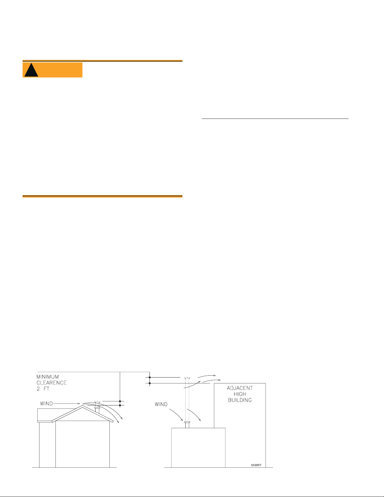
2.
the highest point at which the chimney comes
in contact with the roof, and not less than 2 feet
above the highest roof surface or structure within
10 feet horizontally of the chimney. Refer to Figure 2.
Any accumulation of soot or debris in chimney
3.
offsets should be removed
Any obstructions such as a protruding joint or a
4.
piece of broken tile wedged in the chimney should
be removed.
Fire, Smoke & Asphyxia-
tion Hazard
No other appliance connection should be made to
5.
the same fl ue pipe.
The fl ue pipe should have an upward pitch toward
6.
the chimney of at least 1/4” per foot of length. It
should fi t tightly and should not project into the
chimney.
Any leakage between tiles, around clean-out
7.
doors, or around the vent pipe should be sealed.
INSULATED STAINLESS STEEL CHIMNEY LINERS
The new designs of high effi ciency oil furnaces
and boilers in conjunction with fl ame retention oil
burners are more effi cient. One result of increased
effi ciency is lower fl ue gas temperatures. As
fl ue gases rise in the chimney, they will cool and
condense when they reach the dew point. The
condensation will mix with the sulphur in the fl ue
gases creating sulphuric acid. The acid will attack
the chimney mortar, brick and clay liners causing corrosion, deterioration and blockage of the
chimney. Eventually the blockage could prevent
exhausting the fl ue gases. Instead, the fl ue gases
could vent out the barometric damper into the living space.
Therefore, it is strongly recommended that an ap-
proved insulated stainless steel liner be installed.
For those installations not requiring a chimney,
y
such as through-the-wall vented appliances, follow the instructions given by the appliance and
power venter (if used) manufacturers.
Figure 2 – Chimney Design - Above the Roof
NOTE: Correct
chimney design is
shown by dotted
lines. Incorrect
chimney design,
as shown by the
solid lines, may
result in downdrafts.
Page 6 6104BAFG R06
Page 8
Combustion air supply
WARNING
!
Adequate Combustion
and Ventilation Air Supply
Required
Failure to provide adequate air supply could
seriously affect the burner performance and result in damage to the equipment, asphyxiation,
explosion or fi re hazards.
The burner cannot properly burn the fuel if it is not
y
supplied with a reliable combustion air source.
Follow the guidelines in the latest editions of the
y
NFPA 31 and CSA-B139 regarding providing adequate air for combustion and ventilation.
Appliance located in confi ned space
The confi ned space should have two (2) permanent
openings: one near the top of the enclosure and
one near the bottom of the enclosure. Each opening shall have a free area of not less than (1) one
square inch per 1,000 BTU’s per hour of the total
input rating of all appliances within the enclosure.
The openings shall have free access to the building interior, which should have adequate infi ltration
from the outside.
Exhaust fans and other air-using devices
Size air openings large enough to allow for all air-
using devices in addition to the minimum area required for combustion air. If there is any possibility
of the equipment room developing negative pressure (because of exhaust fans or clothes dryers, for
example), either pipe combustion air directly to the
burner or provide a sealed enclosure for the burner
and supply it with its own combustion air supply.
Inspect/Prepare Installation Site
Outside air kit applications
Refer to separate instruction sheet supplied with
AF/AFG outside air kit for installation. This optional
kit allows combustion air to be piped directly to the
burner (Beckett part number 51747).
Clearances to burner and appliance
Provide space around burner and appliance for
y
easy service and maintenance.
Check minimum clearances against those shown
y
by the appliance manufacturer and by applicable
building codes.
WARNING
!
Failure to comply could result in damage to the
heating equipment and result in fi re or asphyxi-
ation hazards.
When retrofi tting appliances that have unlined
y
stainless steel combustion chambers, protect
the chamber by lining the inside surfaces with a
ceramic fi ber blanket, such as a wet-pac or other
suitable refractory material.
Some steel chambers may not require liners
y
because the appliance was designed and tested
for use with fl ame retention burners. Refer to the
manufacturer’s instructions.
Combustion chamber — Burner retrof tting
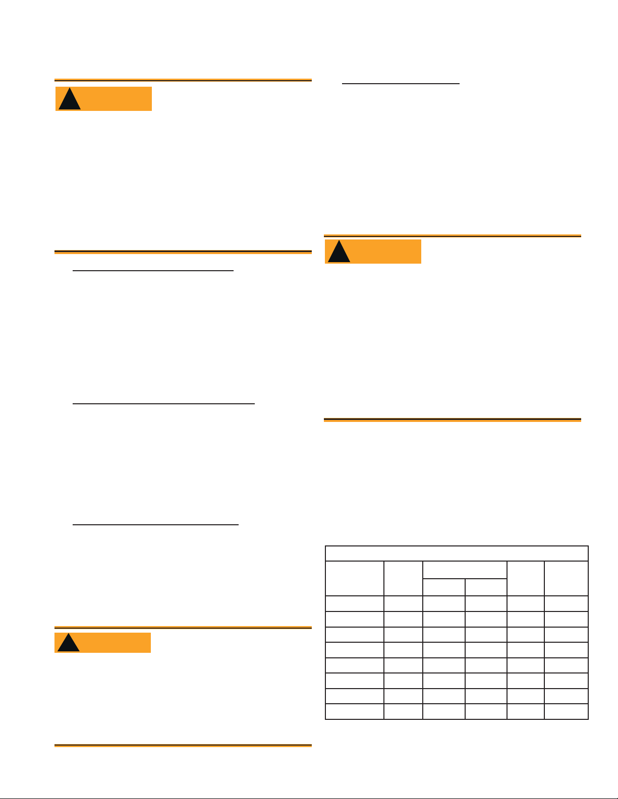
Verify that the appliance combustion chamber pro-
vides at least the minimum dimensions given in
Table 3.
Protect Steel Combustion
Chamber From Burnout
Direct air supply and sidewall venting
Some AFG burners are equipped with combus-
y
tion air boots to allow use of outside air for combustion.
y
When sidewall venting appliances, carefully follow appliance and power venter instructions for
installation and wiring.
WARNING
!
Follow the Outside Air Kit
Instructions Exactly
Failure to comply could result in impaired com-
bustion, appliance soot-up, puffback of smoke,
and fi re or asphyxiation hazards.
Do not attempt to install outside air piping to
y
the burner without using the outside air kit and
instructions.
6104BAFG R06 Page 7
Table 3. Chamber Dimensions
Chamber Dimensions (inches)
Firing Rate
(GPH)
0.50 8 7 8 12 5-6
0.75 9 8 9 12 5-6
1.00 10 9 10 12.5 5-6
1.25 11 10 11 12.5 5-6
1.50 12 11 12 13 6-7
2.00 14 12 15 13.5 6-7
2.50 16 13 17 14 7-8
3.00 18 14 18 15 7-8
Round
I.D.
Rectangular Height Floor to
Width Length
nozzle
Page 9
Inspect/Prepare Installation Site
Prepare the Burner
Low Firing Rate Baff e
The AFG Low Firing Rate Baffl e (LFRB) reduces
the air fl ow and pressure. The LFRB is sometimes
used for fi ring rates under 1.00 gph as listed in
Table 4. Refer to the appliance manufacturer’s instructions. Do not omit the LFRB when specifi ed.
Omitting the baffl e when specifi ed or installing the
baffl e when not specifi ed could result in impaired
burner performance.
Burner fuel unit
Verify that the burner fuel unit is compatible with
y
the oil supply system. For more details, refer to
the pump manufacturer’s instructions provided
with the burner.
Attach air tube (if not already installed)
If using a fl ange and gasket, slide them onto the air
tube. Then attach the air tube to the burner chassis
using the four sheet metal screws provided. Refer
to Figure 4 for details.
Nozzle and Pump Pressure
WARNING
!
Incorrect nozzles and fl ow rates
could result in impaired combustion, under-fi ring, over-fi ring, soot-
ing, puff-back of hot gases, smoke
and potential fi re or asphyxiation hazards.
Use only nozzles having the brand, fl ow rate (gph), spray
angle and pattern specifi ed by the appliance manufac-
turer.
Correct Nozzle and Flow
Rate Required
Table 4. AFG Reduced Firing Rates (with
LFRB)
Burner head type Low Firing Rate Baffl e installed
F0 up to 0.65 gph
F3 or L1 up to 0.85 gph
F4 or F6 up to 0.90 gph
V1 up to 1.00 gph
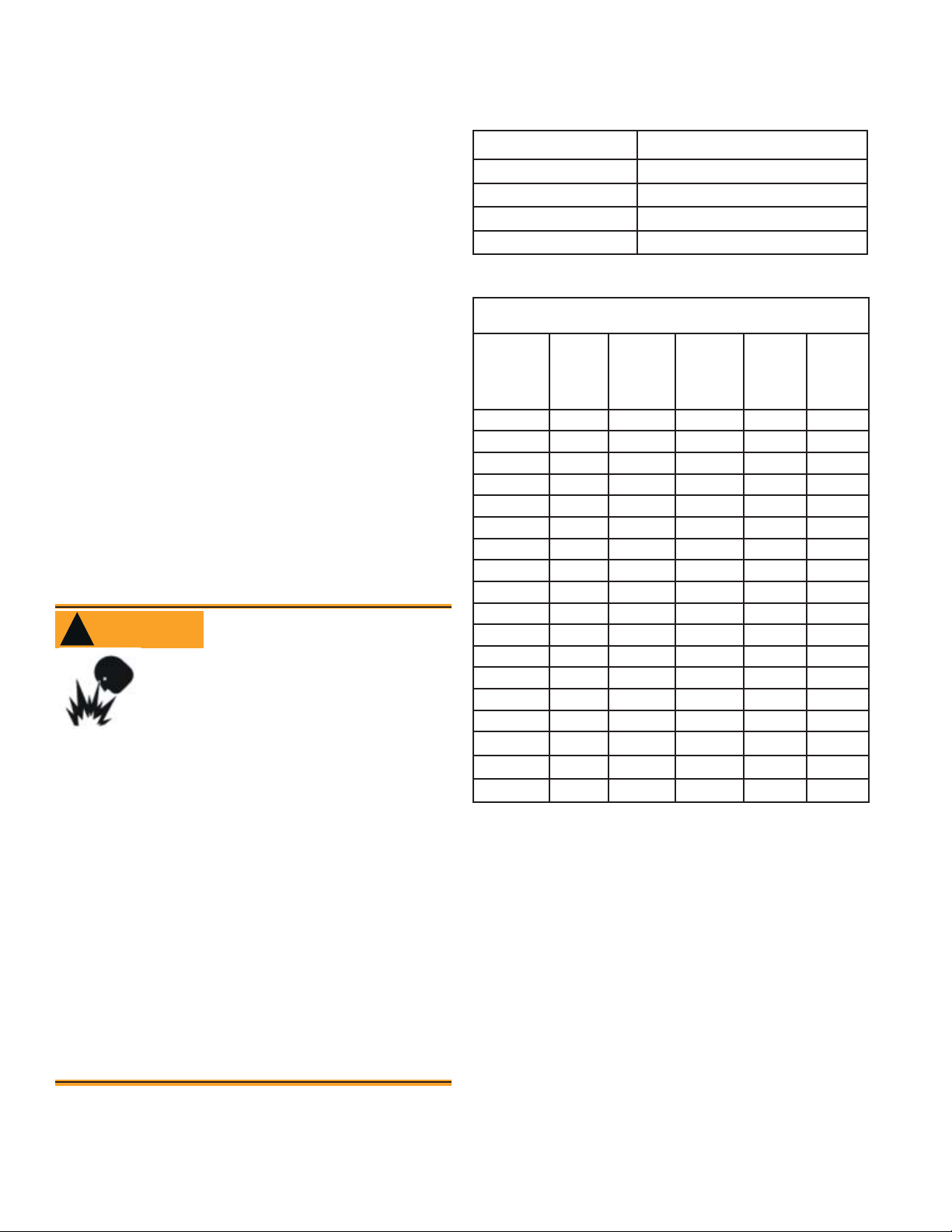
Table 5. Nozzle Flow Rate by Size
Nozzle f ow rate U. S. gallons per hour of No. 2 fuel oil when
pump pressure (psig) is:
Nozzle
size
(rated at
100 psig)
0.40 0.45 0.47 0.49 0.53 0.56
0.50 0.56 0.59 0.61 0.66 0.71
0.60 0.67 0.71 0.74 0.79 0.85
0.65 0.73 0.77 0.80 0.86 0.92
0.75 0.84 0.89 0.92 0.99 1.06
0.85 0.95 1.01 1.04 1.13 1.20
0.90 1.01 1.07 1.10 1.19 1.27
1.00 1.12 1.18 1.23 1.32 1.41
1.10 1.23 1.30 1.35 1.46 1.56
1.20 1.34 1.42 1.47 1.59 1.70
1.25 1.39 1.48 1.53 1.65 1.77
1.35 1.51 1.60 1.65 1.79 1.91
1.50 1.68 1.77 1.84 1.98 2.12
1.65 1.84 1.95 2.02 2.18 2.33
1.75 1.96 2.07 2.14 2.32 2.48
2.00 2.24 2.37 2.45 2.65 2.83
2.25 2.52 2.66 2.76 2.98 -
2.50 2.80 2.96 - - -
125
psi
140 psi 150 psi 175 psi 200 psi
Follow the appliance manufacturer’s specifi cations for
the required pump outlet pressure for the nozzle, since
this affects the fl ow rate.
Nozzle manufacturers calibrate nozzle fl ow rates
y
at 100 psig.
When pump pressures are higher than 100 psig,
y
the actual nozzle fl ow rate will be greater than
the gph stamped on the nozzle body. (Example:
A 1.00 gph nozzle at 140 psig = 1.18 gph)
Securely tighten the nozzle (90 torque inch pounds). For
typical nozzle fl ow rates at various pressures refer to
Table 5.
Install burner nozzle (if not already installed)
Remove the plastic plug protecting the nozzle
1.
adapter threads
Place a 3/4” open-end wrench on the nozzle
2.
adapter. Insert the nozzle into the adapter and fi n-
ger tighten. Finish tightening with a 5/8” open-end
wrench. Use care to avoid bending the burner head
support legs or electrodes. If you remove the head
to replace the nozzle (type “L1”/“L2” or “V1” heads),
carefully reconnect the head to the nozzle adapter,
making sure that the head support makes contact
with the nozzle adapter shoulder. Refer to Figure
5 or 6.
Page 8 6104BAFG R06
Page 10
If the nozzle is already installed, remove the noz-
3.
zle line assembly to verify that the nozzle size and
spray pattern are correct for the application (per appliance manufacturer’s information). Verify that the
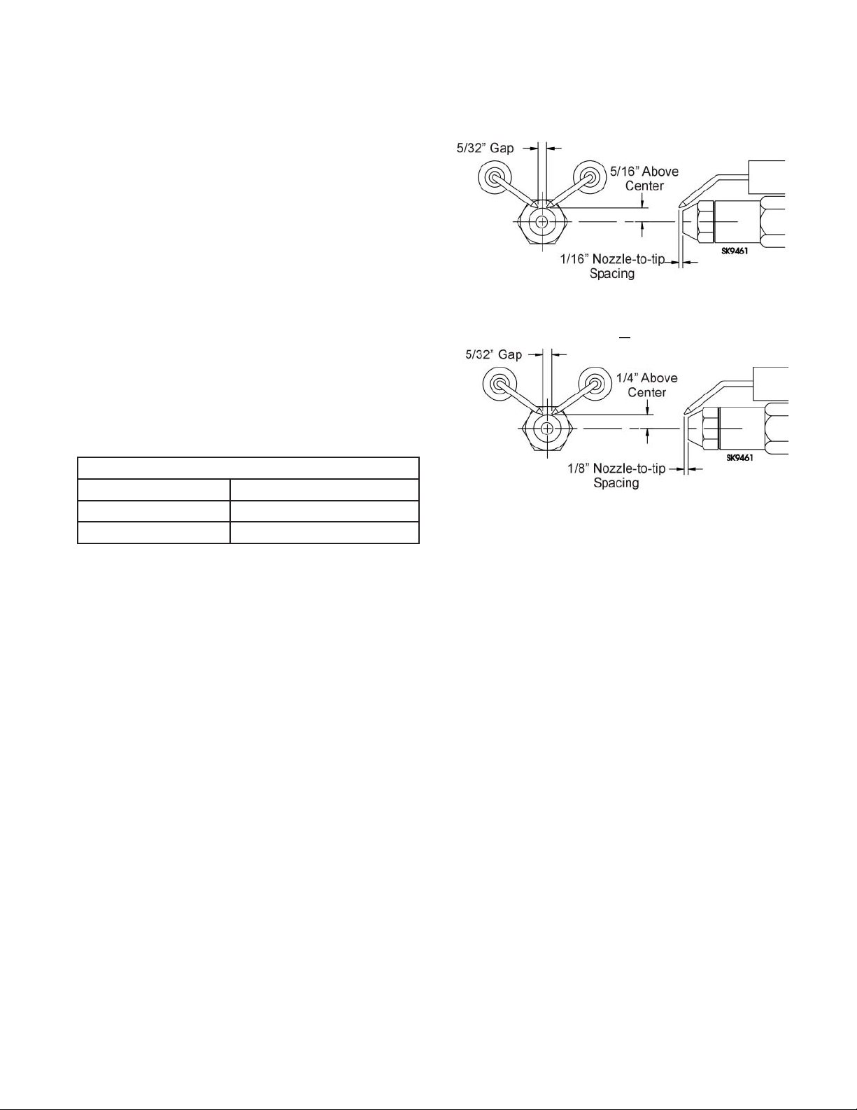
electrode tip settings comply with Figure 3.
If the nozzle is not installed, obtain a nozzle from
4.
the manufacturer, having the capacity and spray
angle specifi ed in the appliance manufacturer’s in-
formation. For conversions or upgrades, when information is not available for the application:
Refer to Table 6 to select the mid-range nozzle
y
spray angle for the head type being used.
Fire the burner and make sure the combustion
y
is acceptable and the fl ame is not impinging on
chamber surfaces.
If a shorter fl ame is needed, select a wider spray
y
angle. If a longer fl ame is needed, select a nar-
rower spray angle.
Either hollow or solid spray patterns may be used.
y
If combustion results are not satisfactory with the
selected spray pattern, try the other pattern.
Table 6. Nozzle Spray Angles
Recommended nozzle spray angles
“F” head 70° or 80° nozzle
“L1” & “L2” head 45°, 60°, or 70° nozzle
“V1” head 45°, 60°, or 70° nozzle
Prepare the Burner
Figure 3. – Electrode Tip Adjustment
Standard Dimensions for F, L1, and V1 Heads.
The Dimensions shown below are for use with L2 heads
and M series air tube combinations ending with an ‘N’ suffi x (example: AFG70MDAQ
N)
Check/adjust electrodes
Check the electrode tip settings. Adjust if neces-
sary to comply with the dimensions shown in Figure 3. To adjust, loosen the electrode clamp screw
and slide/rotate electrodes as necessary. Securely
tighten the clamp screw when fi nished.
Servicing nozzle line assembly
Turn off power to burner before proceeding.
1.
Disconnect oil connector tube from nozzle line.
2.
Loosen the two screws securing igniter retain-
3.
ing clips and rotate both clips to release igniter
baseplate. Then tilt igniter back on its hinge.
Remove splined nut.
4.
“F” head air tube. - Remove nozzle line as-
5.
sembly from burner, being careful not to
damage the electrodes or insulators while
handling. To ease removal of long assemblies
(over 9 inches), rotate assembly 180° from
installed position after pulling partially out of
tube.
“L1”, “L2”, and “V1” head air tubes. - Slide
6.
nozzle line assembly forward (further into air
tube) so the head clears the venturi opening.
Then rotate the nozzle line assembly 90° so
the nozzle line end points up. Pull the nozzle
line assembly toward you and remove assembly from burner.
To replace the nozzle assembly, reverse the
7.
above steps.
6104BAFG R06 Page 9
Mount burner on appliance
Mounting options
Bolt the burner to the appliance using the fac-
1.
tory-mounted fl ange or an adjustable fl ange.
Mounting dimensions
When using the Beckett universal adjustable
1.
fl ange, mount the air tube at a 2° downward
pitch unless otherwise specifi ed by the appli-
ance manufacturer.
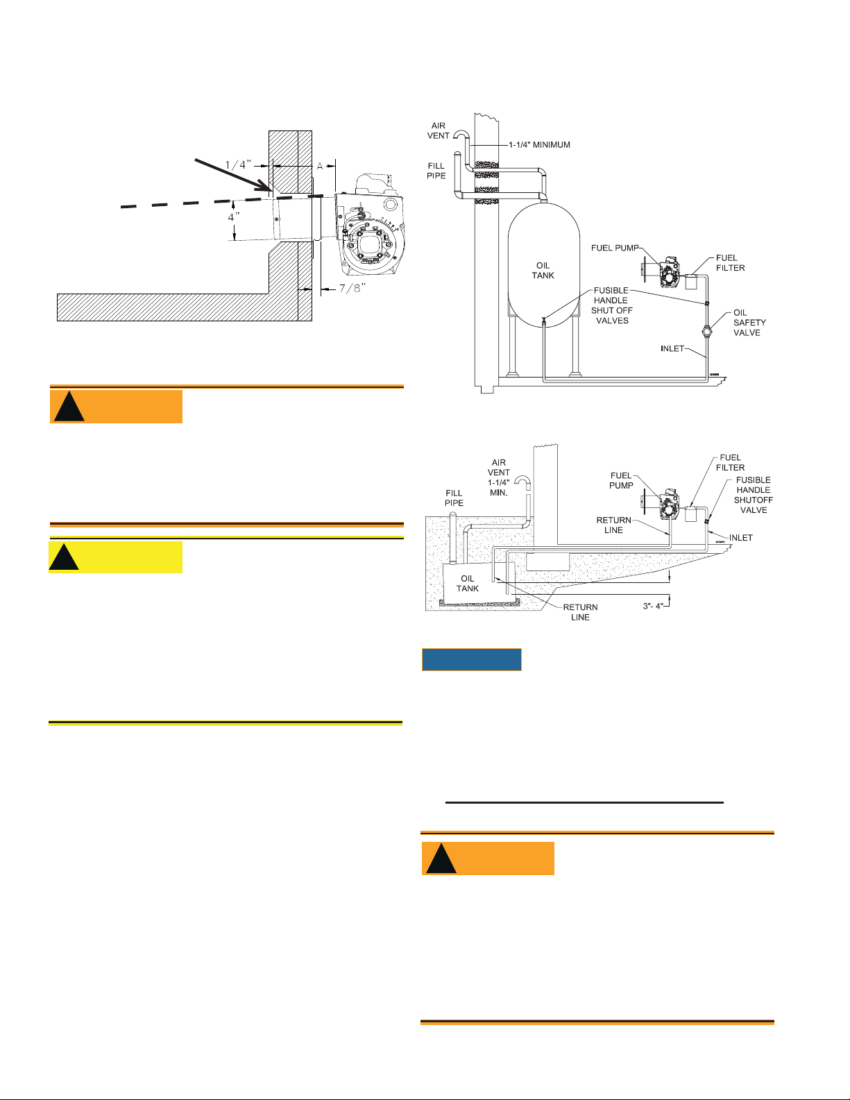
Verify that the air tube installed on the burner
2.
provides the correct insertion depth. See Figure 7.
The end of the air tube should normally be ¼”
3.
back from the inside wall of the combustion
chamber. Never allow the leading edge of the
head assembly to extend into the chamber, unless otherwise specifi ed by the heating appli-
ance manufacturer. Carefully measure the insertion depth when using an adjustable fl ange.
Verify the insertion depth when using a welded
fl ange.
Page 11
Prepare the Burner
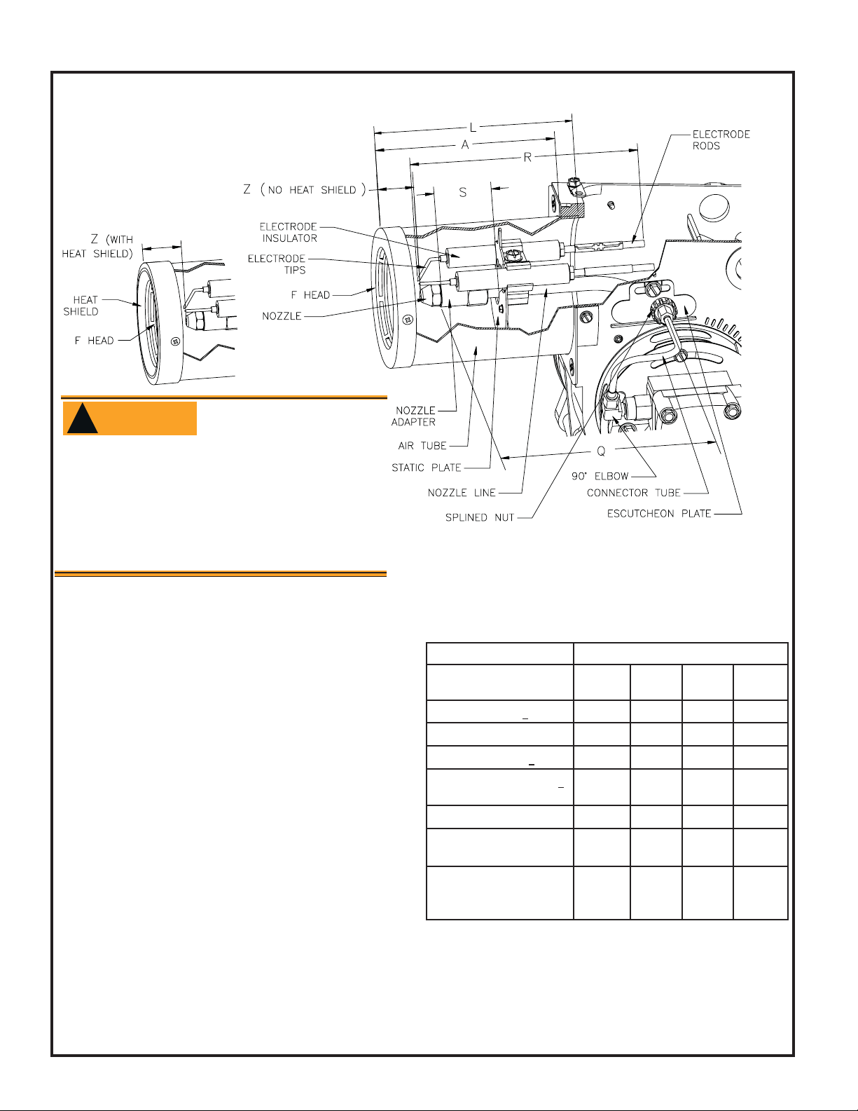
Figure 4. Check/Adjust ‘Z’ Dimension for ‘F’ Heads
1-1/8”
1-3/8”
WARNING
!
Adjust the ‘Z’ dimen-
sion to the required
specif cation.
Incorrect Adjustments could cause combustion problems, carbon deposition from fl ame
impingement, heavy smoke generation and
fi re hazard.
Make all adjustments exactly as outlined in
y
the following information.
Check/Adjust ‘Z’ Dimension - ‘F’ heads
1. The important ‘Z’ dimension is the distance from the face of the nozzle
to the fl at face of the head (or heat shield, if applicable). This dis-
tance for F heads is 1-⅛” (1-⅜” if the air tube has a heat shield). The
“Z” dimension is factory set for burners shipped with the air tube installed. Even if factory set, verify that the “Z” dimension has not been
changed.
2. Use the following procedure to adjust the “Z” dimension, if it is not
correct:
Turn off power to the burner.
y
Disconnect the oil connector tube from the nozzle line
y
See above fi gure. Loosen the splined nut from the nozzle line.
y
Loosen the hex head screw securing the escutcheon plate to the
burner housing.
Place the end of a ruler at the face of the nozzle and, using a
y
straight edge across the head, measure the distance to the face of
the head. A Beckett T501 gauge may also be used.
Slide the nozzle line forward or back until this dimension for F
y
heads is 1-⅛” (1-⅜” to the face of the heat shield, if applicable).
Tighten the hex head screw to secure the escutcheon plate to the
y
burner chassis. Then tighten the splined nut and attach the oil connector tube.
3. Recheck the “Z” dimension periodically when servicing to ensure the
escutcheon plate has not been moved. You will need to reset the “Z”
dimension if you replace the air tube or nozzle line assembly. The
Beckett Z gauge (part number Z-2000) is available to permit checking
the F head “Z” dimension without removing the burner from the appliance.
Burner Dimensions
Dimension (inches)
H (nozzle to head), +
L (Total tube length)
R (electrode length), + 1/4
S (adapter to static plate), +
1/16
Q (nozzle line length),
Z (F head-no heat shield)
(F head-with heat shield)
Z (L1 head w/straight
shroud) (L1/L2/V1 head
w/conic shroud)
Note 1: 1-
through 4-
3/8 for dimension A less than 4”; 1-5/8 for dimension A from 4”
1/2 “, 2-13/32 for dimension A greater than 4-1/2”.
1/32
For usable length A (inches)
F Head L1
Head
N/A
1/2 A+1/2 A+1/2 A+1/2
A+
A+2-1/4 A+1-1/8 A+1-1/8 A+1-1/8
(Note 1) 1-3/8 1-3/8 1-3/8
A+
15/16 A+ 3/16 A+ 3/16 A+ 3/16
1-
1/8
1-3/8
N/A
N/A
1/4 7/32 1/4
N/A
N/A
1-
3/8
1-3/4
L2
Head
N/A
N/A
N/A
1-3/4
V1
Head
N/A
N/A
N/A
1-3/4
Page 10 6104BAFG R06
Page 12
Prepare the Burner
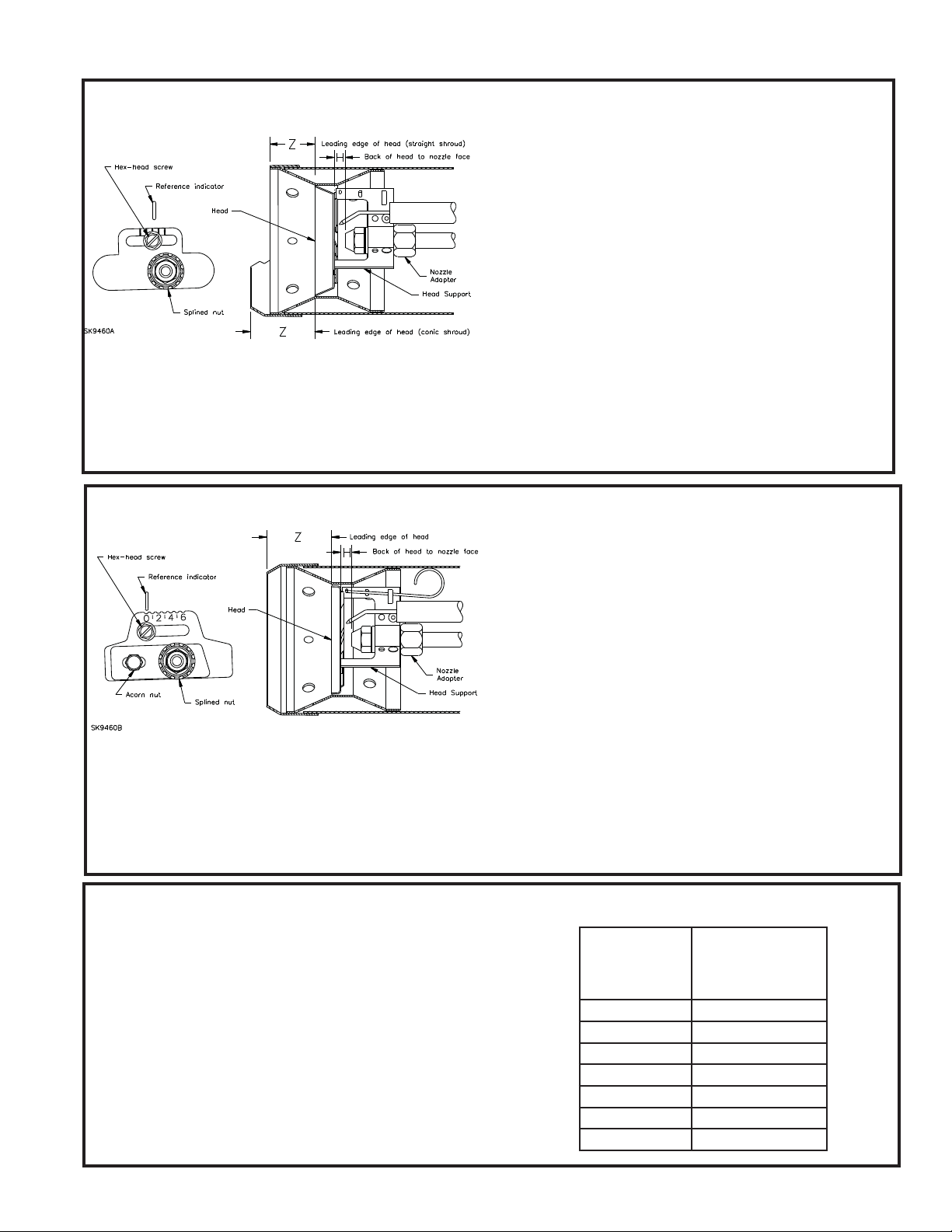
Figure 5. Check/Adjust ‘Z’ Dimension - L1 &
L2 Heads
L1/L2 heads (see Table 7 and Figure 3 for dimensions)
1. See fi gure above. The important “Z” dimension is the distance from
the leading edge of the head to the end of the air tube. This distance
for L1 & L2 heads is 1-⅜” if the tube has a straight shroud or 1-¾” if
the air tube has a conic shroud. The “Z” dimension is factory set for
Figure 6. Check/Adjust ‘Z’ Dimension - V1
Heads
V1 heads (see Table below and Figure above for dimensions)
1. See fi gure above. The important “Z” dimension is the distance from
the leading edge of the head to the end of the air tube. This distance
for V1 heads is 1-¾”. The “Z” dimension is factory set for burners
shipped with the air tube installed. Even if factory set, verify that the
“Z” dimension has not been changed.
burners shipped with the air tube installed. Even if factory set, verify
that the “Z” dimension has not been changed.
2. Use the following procedure to adjust the “Z” dimension, if it is not
correct:
Turn off power to the burner.
y
Disconnect the oil connector tube from the nozzle line.
y
Refer to fi gure. Loosen the splined nut from the nozzle line.
y
Loosen the hex head screw securing the escutcheon plate to the
burner housing.
Place the end of a ruler at the leading edge of the head and, us-
y
ing a straight edge across the end of the air tube, measure the
distance to the end of the tube. A Beckett T501 gauge may also
be used.
Slide the nozzle line forward or back until this dimension is 1-⅜”
y
for L1 & L2 heads if the tube has a straight shroud, or 1-¾” if the
air tube has a conic shroud.
Tighten the hex head screw to secure the escutcheon plate to
y
the burner chassis. Then tighten the splined nut and attach the
oil connector tube.
3. Recheck the “Z” dimension periodically when servicing to ensure
the escutcheon plate has not been moved. You will need to reset
the “Z” dimension if you replace the air tube or nozzle line assembly.
2. Use the following procedure to adjust the “Z” dimension, if it is not
correct:
Turn off power to the burner.
y
Disconnect the oil connector tube from the nozzle line.
y
See fi gure above. Loosen the splined nut from the nozzle line.
y
Loosen the hex head screw securing the head adjusting plate to
the burner housing.
Loosen the acorn nut. Move the head adjusting plate until the “0”
y
lines up with the reference indicator on the housing, and retighten
the hex head screw. Place the end of a ruler at the leading edge of
the head and, using a straight edge across the end of the air tube,
measure the distance to the end of the tube. A Beckett T501 gauge
may also be used.
Slide the nozzle line forward or back until this dimension is 1-¾” for
y
V1 heads. Tighten the acorn nut.
Tighten the hex head screw to secure the head adjusting plate to
y
the burner chassis. Then tighten the splined nut and attach the oil
connector tube.
3. Recheck the “Z” dimension periodically when servicing to ensure the
escutcheon plate has not been moved. You will need to reset the “Z”
dimension if you replace the air tube or nozzle line assembly.
Set head position adjusting plate (V1 head only)
1. After setting “Z” dimension, loosen head adjusting plate hex head
screw and nozzle line splined nut. Move the nozzle line assembly until
the burner reference indicator lines up with the head adjusting plate
setting number given in Table shown below.
2. Tighten the hex head screw and splined nut. (DO NOT loosen the
acorn nut when setting head position.) Refer to the manufacturer’s instructions for OEM settings.
3. The position of the head affects air fl ow volume and pattern. For most
applications, the burner will perform satisfactorily with the air adjustment plate setting of Table shown below.
4. If combustion results indicate the need for change, adjust the head position adjusting plate forward or back one position at a time to optimize
combustion.
6104BAFG R06 Page 11
Table for initial adjusting plate settings for V1
Head
V1 Adjusting
Plate Setting
0 0.75-1.00
1 1.00-1.50
2 1.50-1.75
3 1.75-2.00
4 2.00-2.25
5 2.25-2.50
6 2.50-2.75
AFG with V1
Head
Burner Firing
Rates
Page 13
Mount burner on appliance
Figure 7. – Mounting Burner in Appliance
If space between burner
air tube and opening
exceeds 1/2 inch, pack
burner opening with ceramic fiber refractory.
Tilt down 2
Installing the Oil Tank and Supply System
WARNING
!
Install the oil tank following applicable stan-
dards in the U.S. by referring to the latest
edition of NFPA 31 or CSA-B139 & CSA-B140
in Canada, and all authorities having jurisdiction.
o
SK8745
Oil Leak and Fire Hazard
Figure 8. – Inside Tank Gravity Feed System
Figure 9. – Outside Buried Tank-Lift System
CAUTION
!!
Do Not Use Tef on Tape
Damage to the pump could cause impaired
burner operation, oil leakage and appliance
soot-up.
Never use Tefl on tape on fuel oil fi ttings.
y
Tape fragments can lodge in fuel line compo-
y
nents and fuel unit, damaging the equipment
and preventing proper operation.
Use oil-resistant pipe sealant compounds.
y
Note: to determine the proper fuel line size, refer
to the fuel pump manufacturer’s instructions provided with the burner. Refer to Figure 8 or Figure 9
for typical installation layouts.
Fuel Line Valves and Filter
Install two high quality, oil duty rated, fusible
handle design shutoff valves in accessible locations on the oil supply line. Locate one close to the
tank and the other close to the burner, upstream of
the fi lter for service access.
Install a generous capacity fi lter inside the building
between the fuel tank shutoff valve and the burner,
locating both the fi lter and the valve close to the
burner for ease of servicing. Filter should be rated
for 50 microns or less.
NOTICE
tem and reduce nozzle orifi ce plugging with fi ring rates
below 0.75 gph, a dual fi ltration system can be installed.
This typically consists of a 50 micron primary fi lter,
located near the fuel tank and a secondary fi lter rated for
at least 10 microns located near the burner.
To further protect the fuel supply sys-
Fuel supply level with or above burner –
WARNING
!
Do Not Install By-pass Plug
with 1-Pipe System
Failure to comply could cause Immediate pump
seal failure, pressurized oil leakage and the
potential for a fi re and injury hazard.
The burner is shipped without the by-pass plug
y
installed.
Install the by-pass plug in two-pipe oil supply
y
systems ONLY.
Page 12 6104BAFG R06
Page 14
Wire burner
CAUTION
!!
Oil Supply Pressure
Control Required
Damage to the fi lter or pump seals could cause
oil leakage and a fi re hazard.
The oil supply inlet pressure to the burner can-
y
not exceed 3 psig.
Insure that a pressure limiting device is installed
y
in accordance with the latest edition of NFPA 31.
Do NOT install valves in the return line.
y
(NFPA 31, Chapter 8.)
Gravity Feed Systems: Always install an anti-
y
siphon valve in the oil supply line or a solenoid
valve (RWB Part # 2182602U) in the pump/nozzle discharge tubing to provide backup oil fl ow
cut-off protection.
The burner may be equipped with a single-stage
fuel unit for these installations. Connect the fuel
supply to the burner with a single supply line if you
want a one-pipe system (making sure the bypass
plug is NOT installed in the fuel unit.) Manual bleeding of the fuel unit is required on initial start-up. If
connecting a two-pipe fuel supply, install the fuel
unit bypass plug.
Fuel supply below the level of the burner –
When the fuel supply is more than eight feet below
the level of the burner, a two-pipe fuel supply system is required. Depending on the fuel line diameter and horizontal and vertical length, the installation may also require a two-stage pump. Consult
the fuel unit manufacturer’s literature, included with
the burner, for lift and vacuum capability.
Fuel line installation –
Continuous lengths of heavy wall copper tubing
y
are recommended. Always use f are f ttings.
Never use compression f ttings.
Always install fi ttings in accessible locations.
y
Proper routing of fuel lines is required to prevent
air cavitation and vibration.
Frozen Plumbing and
Water Damage Hazard
If the residence is unattended in severely cold
weather, burner primary control safety lockout,
heating system component failures, power
outages or other electrical system failures
could result in frozen plumbing and water
damage in a matter of hours. For protection,
take preventive actions such as having a
security system installed that operates during
power outages, senses low temperature and
initiates an effective action. Consult with your
heating contractor or a home security agency.
Wire burner
Burner packaged with appliance
WARNING
!
Electrical shock can cause severe
personal injury or death.
Disconnect electrical power before installing or
y
servicing the burner.
Provide ground wiring to the burner, metal con-
y
trol enclosures and accessories. (This may also
be required to aid proper control system operation.)
Perform all wiring in compliance with the Na-
y
tional Electrical Code ANSI/NFPA 70 (Canada
CSA C22.1)
y
Refer to appliance manufacturer’s wiring diagram
for electrical connections.
Burner installed at jobsite
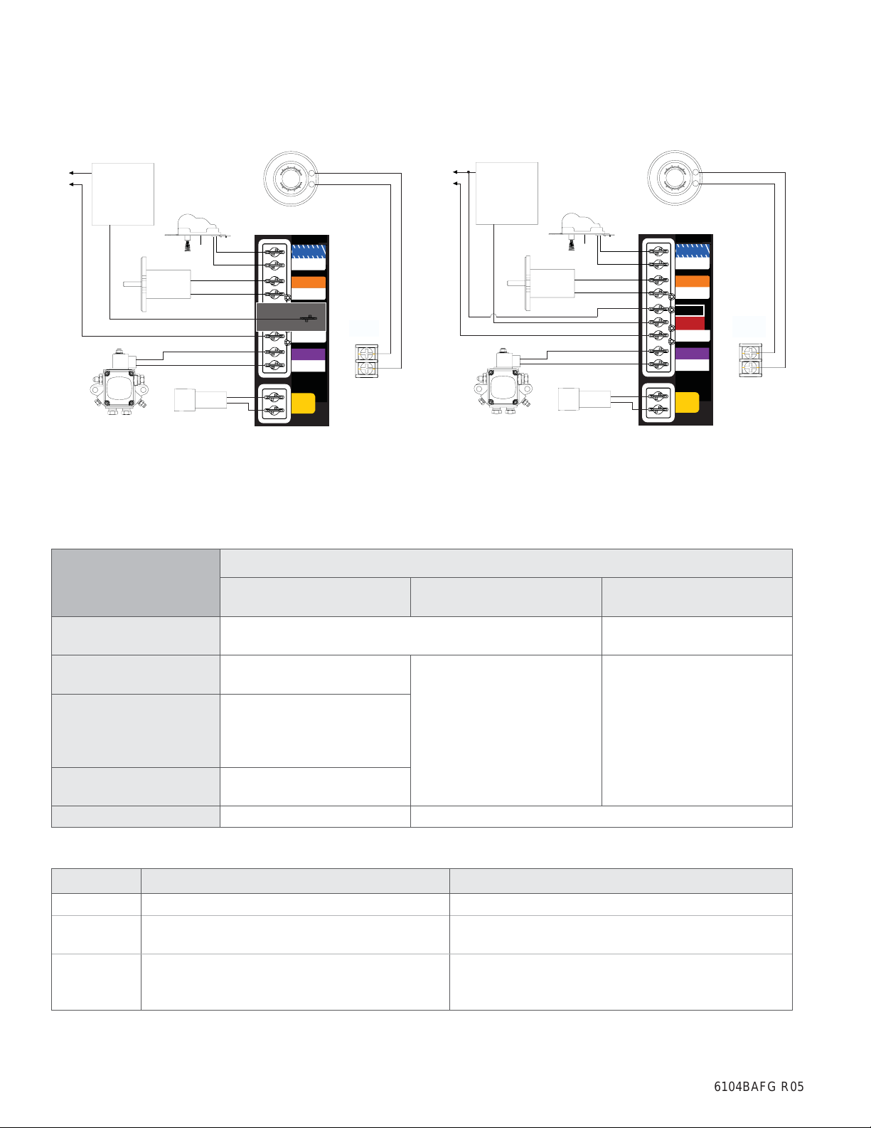
Refer to Figures 11a and 11b, for typical burner
y
wiring, showing cad cell primary controls. Burner
wiring may vary, depending on primary control
actually used.
Refer to the appliance manufacturer’s wiring dia-
y
gram prior to connecting the burner wiring. All wiring must be in accordance with the latest revision
of National Electric Code NFPA 70 and all local
codes and regulations. In Canada, all wiring is
to be in accordance with the Canadian Electrical
Code, Part 1.
The 7505 primary control with valve-on delay (pre-
time) and burner motor-off delay (post-time) requires a constant 120 volts AC power source supplied to the BLACK wire on the control. The RED
wire goes to the appliance limit circuit. Please note
that other control manufacturers may use different
wire colors for power and limit connections.
Special wiring required with covered
burners
The mounting plate is not a conduit connec-
tion point. Pass conduit and attached connector
through the opening in the mounting plate and attach it directly to the burner-mounted 4x4 electrical
box.
If attaching a burner cover to a previously installed
burner, attach the mounting plate and then slide the
conduit into the “J” shaped conduit slot.
Electrical Shock Hazard
6104BAFG R06 Page 13
Page 15
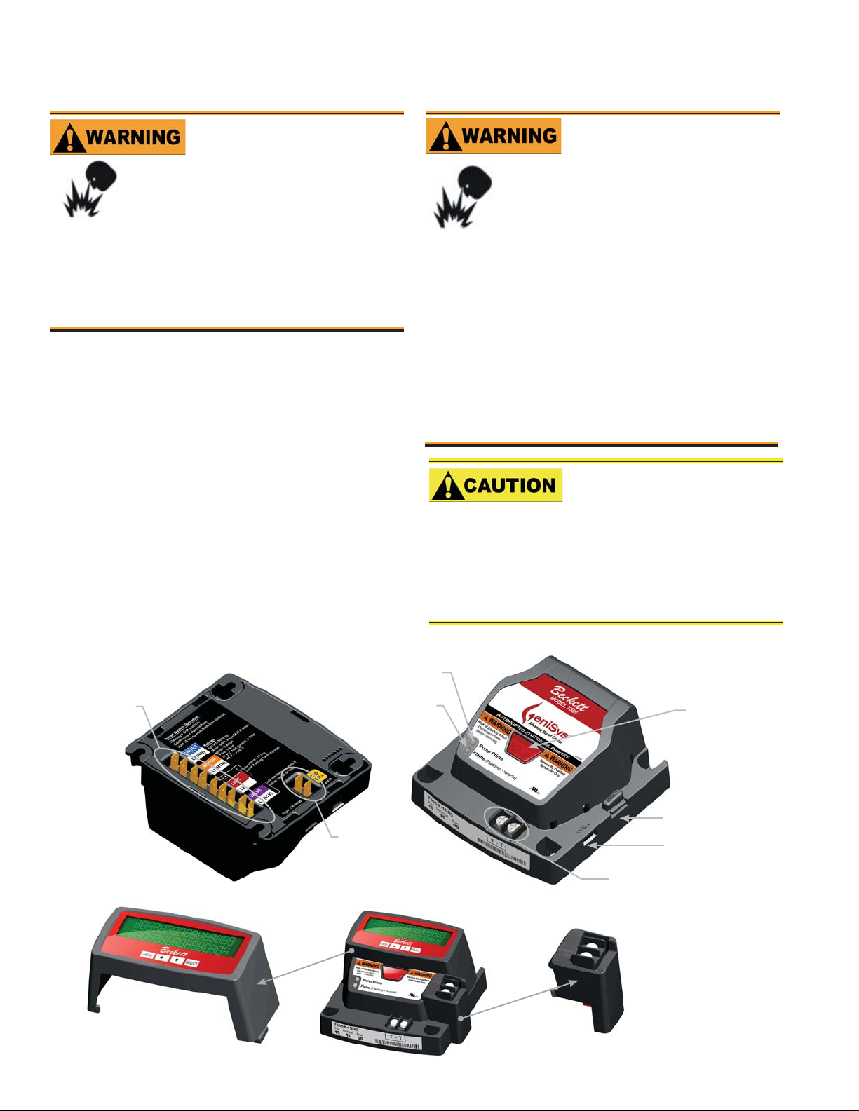
Burner Controls
GeniSys Model 7505 Control Wiring
Fire or Explosion Hazard
Can cause severe injury, death, or
property damage.
The control can malfunction if it gets wet,
y
leading to accumulation of oil or explosive oil
vapors.
Never install where water can fl ood, drip or
y
condense on the control.
Never use a control that has been wet - replace it.
y
Features
Thermostat / Operating and Limit Control Compatible
•
•
Welded Relay Protection
•
Limited Recycle
•
Limited Reset
•
3 Status Lights
•
Valve-On Delay / Motor-Off Delay (Field
programmable with 52067 GeniSys Display)
•
15 Second Lockout Time
•
Interrupted or Intermittent Duty Ignition
•
Technician Pump Priming Mode
•
Disable Function
•
Cad Cell Resistance Indicator
•
Communication Ports
Figure 10.
Explosion, Fire, Scald,
and Burn Hazard
All heating appliances must have
HIGH LIMIT protection to interrupt
electrical power and shutdown the
burner if operating or safety controls
fail and cause a runaway condition.
Follow the appliance manufacturer’s wiring
y
diagrams and note all required safety controls.
Typical safety controls include high temperature
y
or pressure limits, low water cutoffs, pressure
relief valves and blocked fl ue sensing switches.
Verify all limit and safety controls are installed
y
and functioning correctly, as specifi ed by the
manufacturer, applicable safety standards,
codes and all authorities having jurisdiction.
Ensure that the appliance is free of oil and oil
y
vapor before starting or resetting the burner.
Incorrect Wiring Will Result in Improper Control
Operation
GeniSys wiring label colors may not match the
y
wire colors of the burner or other manufacturers’
controls.
The GeniSys Control should be wired according
y
to the appliance manufacturer’s instructions.
Yellow Light
Wiring
Connections
Display Module:
For programming and
diagnostics
Page 14 6104BAFG R06
Green Light
Cad Cell
Connections
Thermostat Terminals
Alarm Module:
For adding isolated
low voltage alarm
contacts to the base
control. See Alarm
Module Instructions for
specifi cations.
Reset Button
with Red Light
Communication Port 2
Communication Port 1
Page 16
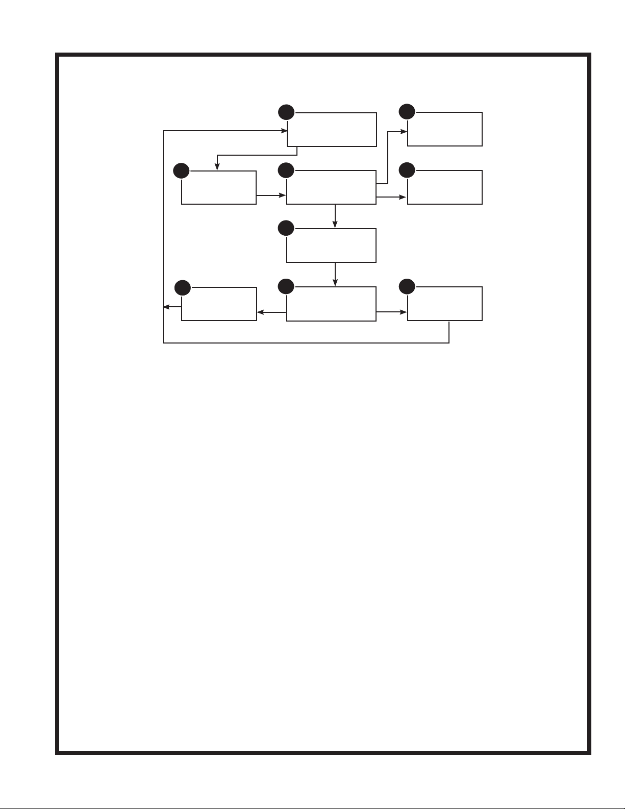
Typical Burner Sequence of Operation for GeniSys 7505 Control.
Refer to the appliance manufacturer’s wiring diagram for actual specifi cations.
Burner Controls
1
2
Valve-on delay
8
Motor-off delay
Standby: The burner is idle, waiting for a call for
1.
3
5
6
heat.
Valve-On Delay: The igniter and motor are on while
2.
the control delays turning on the oil solenoid valve
for the programmed time.
Trial For Ignition : The oil solenoid valve is
3.
energized. A fl ame should be established within the
factory set trial for ignition time (lockout time).
Lockout: The control has shut down for one of the
4.
following safety reasons:
a. The trial for ignition (lockout) time expired without
fl ame being established.
b. The cad cell detected fl ame at the end of the
Valve On Delay state.
To reset the control from lockout click the button 1-
second.
Standby
Trial for
ignition
Ignition carryover
Run
6. Run: The fl ame is sustained until the call for heat
is satisfi ed. The burner is then sent to Motor-Off
Delay, if applicable, or it is shut down and sent to
Standby.
7. Recycle: If the fl ame is lost while the burner is
fi ring, the control shuts down the burner, enters a
60 second recycle delay, and repeats the ignition
sequence. The control will continue to Recycle
each time the fl ame is lost, until it reaches a pre-set
time allotment. The control will then go into Hard
Lockout instead of recycle. This feature prevents
excessive accumulation of oil in the appliance fi ring
chamber.
8. Motor-Off Delay: If applicable, the oil solenoid
valve is turned off and the control delays turning the
motor off for the set motor-off delay time before the
control returns to standby.
9
Pump
prime
4
Lockout
7
Recycle
NOTE: A recurrence of the above failure modes or a
failed welded relay check could cause the control to
enter a Hard Lockout state that must be reset only
by a qualifi ed service technician.
To reset from Hard Lockout, hold the reset button for
9. Pump Prime: The igniter and motor are on with the
oil solenoid valve energized for 4 minutes. During
Pump Prime mode, the cad cell is disregarded,
allowing the technician to prime the pump without
having to jumper the cad cell.
15 seconds until the yellow light turns on.
5. Ignition Carryover: Once fl ame is established,
the igniter remains on for 10 additional seconds to
ensure fl ame stability.
6104BAFG R06 Page 15
Page 17
Burner Controls
6104BAFG R06
Figure 1 1a. – Interrupted ignition, valve-on delay
only (no motor-off delay)
70
60
80
L1
L2
OIL VALVE
SAFETY AND
OPERATING
LIMITS
IGNITER
MOTOR
CAD CELL
50
50
80
60
70
THERMOSTAT
IGNITER
L2 (IGN)
MOTOR
L2 (MTR)
LIMIT
L1
LIMIT
L2
VALV E
L2 (VLV)
CAD
CELL
W
R
L1 - LIMIT
JUMPER
TR
TW
TR-TW TERMINALS
LOCATED ON OPPOSITE
SIDE OF CONTROL
TR-TW
JUMPER
Figure 1 1b. – Interrupted ignition, valve-on delay
and motor-off delay
70
60
80
L1
L2
OIL VALVE
SAFETY AND
OPERATING
LIMITS
IGNITER
MOTOR
CAD CELL
50
50
80
60
70
THERMOSTAT
IGNITER
L2 (IGN)
MOTOR
L2 (MTR)
L1
LIMIT
L2
VALV E
L2 (VLV)
CAD
CELL
W
R
TR
TW
TR-TW TERMINALS
LOCATED ON OPPOSITE
SIDE OF CONTROL
Reset Button Operation
Table 2 explains what action the control will take when the reset button is pressed for different lengths of time
during the various burner operating states.
TR-TW
JUMPER
Table 2 - Reset Button Operation
If the burner is in the
below state:
Button Click
(press < 1 second)
Lockout Reset from Soft Lockout
Valve-on Delay, Trial for
Ignition, Ignition Carryover
Go to Pump Prime (see
“Priming the Pump” above)
Yellow light fl ashes to indicate
Run (igniter is shut off)
cad cell resistance. See “Cad
Cell Resistance Indicator” for
table of resistance values.
Motor-Off Delay,
No action
Pushing the reset button will:
Button Hold
(press > 1 second)
Disable the Burner:
Any time the burner is running,
press and hold the reset button
to disable the burner. The
burner will remain off as long
as the button is held.
Button Hold
(press 15+ seconds)
Reset from Restricted (Hard)
Lockout
Enables Pump Priming:
After the reset button has been
held for 15 seconds, the button
can then be clicked during the
next ignition sequence to enter
Pump Prime mode.
Standby
Pump Prime No action Exit Pump Prime mode and return to Standby
Table 3 - Status Lights
Light Color On Continuously Flashing
Red Restricted (Hard) Lockout Soft Lockout
Green Flame Sensed during normal operation (Could
Recycle
be stray light during standby)
Yellow Control is in Pump Prime mode or
Reset button currently held for 15+ seconds.
Cad Cell resistance. See “Cad Cell Resistance
Indicator” on page 18 for a table of resistance
values.
Page 16 6104BAFG R05
Page 18
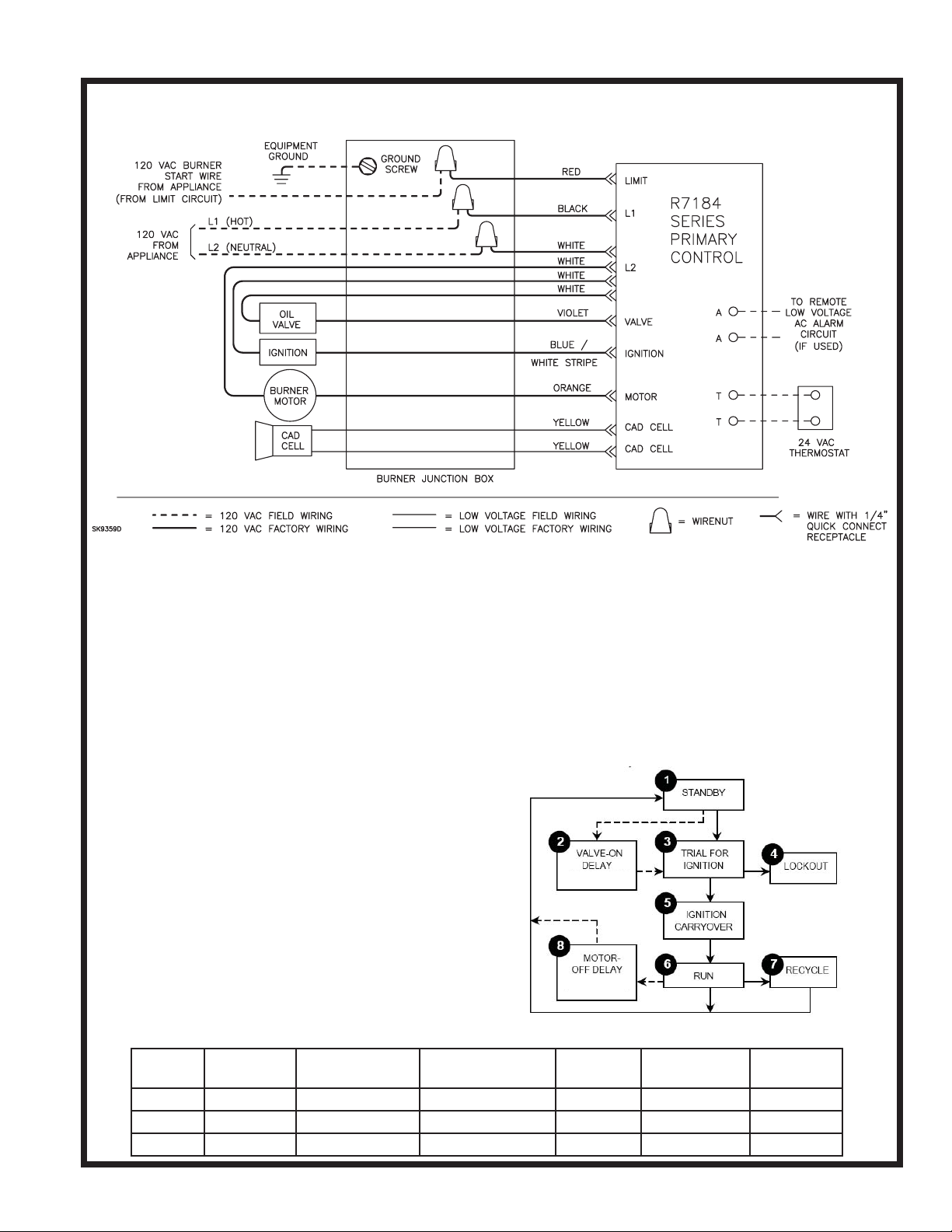
Burner Controls
Typical Burner Wiring & Burner Sequence of Operation for R7184P Control.
Refer to the appliance manufacturer’s wiring diagram for actual specifi cations.
Figure 10. – Typical Burner Wiring
1. STANDBY. The burner is idle, waiting for a call for
heat. When a call for heat is initiated, there is a 310 second delay while the control performs a safe
start check.
2. VALVE-ON DELAY. The ignition and motor are
turned on for a 15 second valve-on delay.
3. TRIAL FOR IGNITION (TFI). The fuel valve is
opened. A fl ame should be established within the
15 second lockout time.
4. LOCKOUT. If fl ame is not sensed by the end of
the TFI, the control shuts down on safety lockout
and must be manually reset. If the control locks out
three times in a row, the control enters restricted
lockout.
5. IGNITION CARRYOVER. Once fl ame is estab-
lished, the ignition remains on for 10 seconds to
ensure fl ame stability before turning off. If the con-
trol is wired for intermittent duty ignition, the ignition
unit stays on the entire time the motor is running.
6. RUN. The burner runs until the call for heat is satifi ed. The burner is then sent to burner motor off
delay, if applicable, or it is shut down and sent to
standby.
Control System Features
Feature Interrupted
ignition
R7184A YES YES YES — — —
R7184B YES YES YES YES — —
R7184P YES YES YES YES YES Optional
Limited reset,
Limited recycle
Diagnostic LED,
cad cell indicator
7. RECYCLE. If the fl ame is lost while the burner is
fi ring, the control shuts down the burner, enters a 60
second recycle delay, and then repeats the above
ignition sequence. If fl ame is lost three times in a
row, the control locks out to prevent cycling with
repetitious fl ame loss due to poor combustion.
8. BURNER MOT OR-OFF DELA Y. The fuel valve
is closed and the burner motor is kept on for the
selected motor-off delay time before the control returns the burner to standby.
Valve-on
delay
Burner motor
off delay
Alarm Con-
61351
tacts
6104BAFG R0 Page 17
Page 19

Wire burner
NOTICE
could cause erratic cycling of the burner control.
y
Connect the wire from the R
thermostat to the TR terminal on the control.
Connect the wire from the W terminal on the
y
thermostat to the TW terminal on the control.
Make connections to the control’s terminals as shown
○
in Figures 11a and 11b. Refer to the label on the un-
derside of the control for wiring details.
Note: Motor-off delay on a 7505P will be disabled if
○
the safety and operating limits as shown in Figures
11a and 11b interrupt power to the control terminal
L1.
Connect thermostat leads to the TR and TW
○
terminals on the control or jumper the TR and
TW terminals on the control, as directed by the
appliance wiring diagram.
Thermostat anticipator Current: 0.1 amp
▪
Thermostat voltage: 24 volts AC
▪
Note that if the thermostat short cycles or operates
improperly, it may require an isolation relay for proper
operation. The Beckett A/C Ready Kit (part no. 51950U)
provides this function. Wiring instructions are included
with the A/C Ready Kit.
Some Thermostats Are Polar-
ity Sensitive. Reversed polarity
or R terminal on the
H
Start up burner/set combustion
3.
Set the thermostat substantially above room temperature.
4.
Close the line voltage switch to start the burner.
If the burner does not start immediately you may
have to reset the burner primary control.
5.
Initiate a call for heat.
6.
After the burner starts, press and hold the reset
button for 15 seconds until the yellow light turns on.
This indicates that the button has been held long
enough.
7.
Release the reset button. The yellow light will turn
off and the burner will start up again.
8.
At burner start up, click the reset button while the
igniter is still on. This will transition the control to a
dedicated Pump Prime mode, during which the motor, igniter, and valve are powered for four minutes.
The yellow light will be on.
9.
Bleed the pump until all froth and bubbles are
purged. If desired, terminate the call for heat or
hold the reset button for at least one second to exit
Pump Prime mode and return to Standby.
10.
At the end of 4 minutes, the yellow light will turn off
and the control will automatically return to standby
mode.
11.
If prime is not established during the four minute
pump prime mode, return to step 8 to re-enter Pump
Prime mode. Repeat steps 8 through 10 until the
pump is fully primed and the oil is free of bubbles.
12.
Terminate the call for heat, and the control will resume normal operation.
Cad Cell Resistance Indicator
▪
During the burner Run state, click the reset button
○
(less than 1 second) to check the cad cell resistance
range. The yellow light will fl ash 1 to 4 times, de-
pending on the amount of light detected by the cad
cell. See chart below:
Hot Gas Puff-Back and
Heavy Smoke Hazard
Failure to prime the pump properly could result
in unstable combustion, hot gas puff-back and
heavy smoke.
Do not allow oil to spray into a hot combustion
y
chamber while bleeding air from the pump.
Install a gauge in the nozzle discharge port
y
tubing or fully open the pump bleed valve to
prevent oil spray from accumulating in the combustion chamber during the air bleed procedure.
Ensure that all bubbles and froth are purged
y
from the oil supply system before tightening the
pump bleed valve.
Ensure that the appliance is free of oil and oil
y
vapor before starting or resetting the burner.
Open the shutoff valves in the oil supply line to the
1.
burner.
Close air band and partially open air shutter. This
2.
is an initial air setting for the pump bleeding procedure only. Additional adjustments must be made
with instruments.
Page 18 6104BAFG R0
▪
Yellow Light Flashes Flame Detection Range
1 Normal (0 - 400 ohms)
2 Normal (400 - 800 ohms)
3 Normal (800 - 1600 ohms)
4 Limited (1600 ohms - Lockout)
Resetting From Restricted or Hard Lockout
If the control continues to lockout without a satisfi ed
○
call for heat, or fails the motor relay check, the control
enters Hard (restricted) Lockout in order to limit accumulation of unburned oil in the combustion chamber.
To reset, hold the button down for 15 seconds until
○
the red light turns off and the yellow light turns on.
Always verify the control functions according to all
○
specifi cations before leaving the installation site.
Replace the control if it does not operate as speci-
○
fi ed.
Page 20

Startup / Checkout
WARNING
Explosion and Fire Hazard
!
Failure to follow these instructions
could lead to equipment malfunction and result in heavy smoke
emission, soot-up, hot gas puffback, fi re and asphyxiation hazards.
Do not attempt to start the burner when excess
y
oil has accumulated in the appliance, the appliance is full of vapor, or when the combustion
chamber is very hot.
Do not attempt to re-establish fl ame with the
y
burner running if the fl ame becomes extin-
guished during start-up, venting, or adjustment.
Vapor-Filled Appliance: Allow the unit to cool
y
off and all vapors to dissipate before attempting
another start.
Oil-Flooded Appliance: Shut off the electrical
y
power and the oil supply to the burner and then
clear all accumulated oil before continuing.
If the condition still appears unsafe, contact the
y
Fire Department. Carefully follow their directions.
Keep a fi re extinguisher nearby and ready for
y
use.
If the burner or control fails any of the following tests,
recheck control wiring. If the burner or control still fails
any tests, replace the control.
Startup/Checkout
4.
After the 60 second recycle period, the control
will try to restart the system.
5.
After the 15 second lockout time, the control
will lock out the burner and the reset button will
fl ash. Verify that the burner motor and igniter
are off and that the burner oil solenoid valve (if
used) is not energized.
6.
Open the hand valve in the oil line.
7.
Click the reset button and verify that the red light
in the reset button shuts off and that the burner
lights.
8.
End the call for heat.
○
Before leaving the installation, verify that all thermostat and boiler/furnace control wiring is correct. Consult heating appliance manual for directions.
Set combustion with instruments
CAUTION
!!
FLUES HAVING SUFFICIENT DRAFT AT ALL TIMES
TO ENSURE SAFE AND PROPER OPERATION OF
THE BURNER.
Allow the burner to run for approximately 5 to 10
1.
minutes.
OIL-BURNING EQUIPMENT
SHALL BE CONNECTED TO
Check Safety Features
▪
Safe Start Check
○
Place a jumper across the cad cell terminals.
1.
Refer to the steps for “Start up burner/set
2.
combustion” and have the system call for heat.
Burner must not start. Verify that the green light
3.
is on continuously and that the control remains
in Standby mode.
End the call for heat and remove the cad cell
4.
jumper.
Simulate Flame Failure and Ignition Failure
○
Refer to the steps for “Start up burner/set
1.
combustion” and have the system call for heat.
After fl ame is established and the burner igniter
2.
turns off, close the hand valve in the oil supply
line.
At fl ame loss, the control will enter Recycle
3.
mode. Verify that the green light is fl ashing. The
control will remain in Recycle for 60 seconds.
Set the stack or over-fi re draft to the level specifi ed
2.
by the appliance manufacturer.
Natural Draft Applications; typically over-fi re
y
draft is -0.01” or -0.02” w.c.
Direct V enting; typically may not require draft
y
adjustment.
High Eff ciency/Positive Pressure Appliances;
y
also vary from traditional appliances (see manufacturer’s recommendations).
Follow these four steps to properly adjust the burn-
3.
er:
Step 1: Adjust the air shutter/band until a trace of
smoke is achieved.
Step 2: At the trace of smoke level, measure the
CO
(or O2) . This is the vital reference
2
point for further adjustments. Example:
13.5% CO
Step 3: Increase the air to reduce the CO
1.5 to 2 percentage points. (O2 will be increased by approximately 2.0 to 2.7 percentage points.) Example: Reduce CO
from 13.5% to 11.5% (2.6% to 5.3% O2).
(2.6% O2)
2
by
2
2
6104BAFG R0 Page 19
Page 21

Perform regular maintenance
Step 4: Recheck smoke level. It should be Zero.
This procedure provides a margin of
•
reserve air to accommodate variable
conditions.
If the draft level has changed, recheck
•
the smoke and CO
the burner if necessary
Once combustion is set, tighten all fasteners on air
4.
band, air shutter and head adjusting plate or escutcheon plate.
Burner equipped with cover - Reinstall the cover
5.
and repeat Steps 2 and 4. If CO2 increases (O2
decreases), remove the cover and adjust the air
setting so the CO2 (O2) with cover on meets requirements of Step 3.
Start and stop the burner several times to ensure
6.
satisfactory operation. Test the primary control and
all other appliance safety controls to verify that they
function according to the manufacturer’s specifi ca-
tions.
levels and readjust
2
Perform regular maintenance
WARNING
!
Tampering with or making incorrect
adjustments could lead to equipment malfunction and result in
asphyxiation, explosion or fi re.
DO NOT TAMPER WITH THE UNIT OR CON-
y
TROLS - CALL YOUR QUALIFIED SERVICE
TECHNICIAN OR SERVICEMAN.
To ensure continued reliable operation, a quali-
y
fi ed service technician must service this burner
annually.
More frequent service intervals may be required
y
in dusty or adverse environments.
Operation and adjustment of the burner requires
y
technical training and skillful use of combustion
test instruments and other test equipment.
Annual Professional Ser-
vice Required
Verify the nozzle is the one originally specifi ed by
the appliance manufacturer and replace the nozzle with one having the exact specifi cations from
the same manufacturer.
Clean and inspect the electrodes for damage, re-
placing any that are cracked or chipped.
Check electrode tip settings. Replace electrodes
if tips are rounded.
Inspect the igniter spring contacts. Clean or re-
place if corroded.
Clean the cad cell grid surface, if necessary.
Make sure Low Firing Rate Baffl e is in place if
required for the burner application. Omitting the
baffl e can result in unacceptable burner combus-
tion.
Inspect all gaskets. Replace any that are dam-
aged or would fail to seal adequately.
Inspect the combustion head and air tube. Re-
move any carbon or foreign matter. Replace all
damaged units with exact parts.
Clean the blower wheel, air inlet, air guide, burner
housing and static plate of any lint or foreign material.
If motor is not permanently lubricated, oil motor
with a few drops of SAE 20 nondetergent oil at
each oil hole. DO NOT over oil motor. Excessive
oiling can cause motor failure.
Check motor current. The amp draw should not
exceed the nameplate rating.
Check all wiring for secure connections or insula-
tion breaks.
Check the pump pressure and cutoff function.
Check primary control safety lockout timing.
Check ignition system for proper operation.
Inspect the vent system and chimney for soot ac-
cumulation or other restriction.
Clean all fl ue passages and fl ue pipe. Replace
corroded or damaged pipes.
Clean the appliance thoroughly according to the
manufacturer’s recommendations.
Check the burner performance. Refer to the sec-
tion “Set combustion with test instruments”.
It is good practice to make a record of the service
performed and the combustion test results.
Shutting the Burner Off
CAUTION
Replace the oil supply line fi lter. The line fi lter car-
tridge must be replaced to avoid contamination of
the fuel unit and nozzle.
Inspect the oil supply system. All fi ttings should
be leak-tight. The supply lines should be free of
water, sludge and other restrictions.
Remove and clean the pump strainer if applica-
ble.
Page 20 6104BAFG R0
!!
TIME, ALWAYS KEEP THE VALVE SHUT OFF.
Turn off all electric power to the burner.
Note: There could be more than one disconnect
switch.
IF THE BURNER IS SHUT DOWN
FOR AN EXTENDED PERIOD OF
Page 22
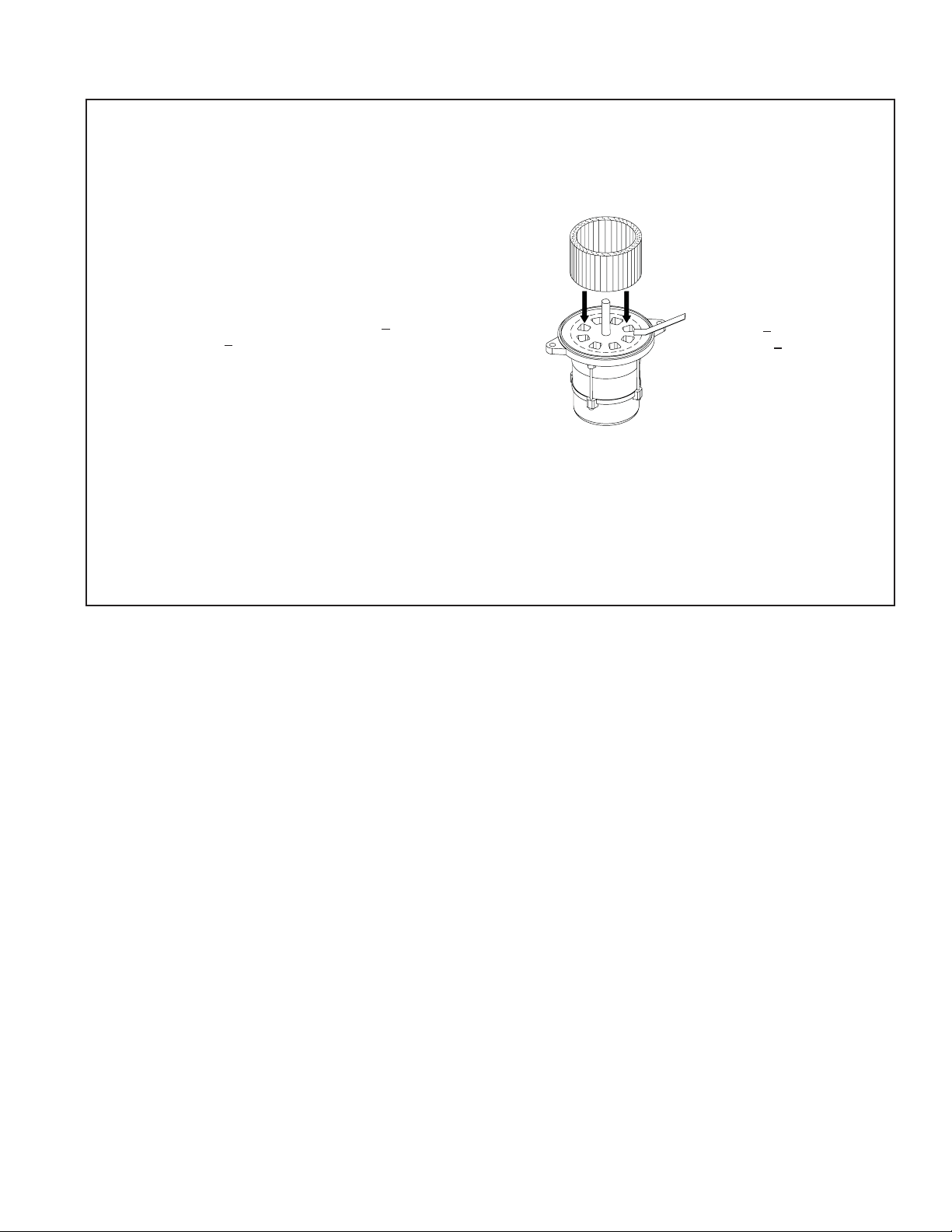
Replace the blower wheel:
Turn off all power to the burner before servic-
1.
ing.
Disconnect the burner motor wires.
2.
Remove the bolts securing the motor to the
3.
burner housing.
Remove the motor and blower wheel.
4.
Remove the existing blower wheel.
5.
Referring to the fi gure below, slide the new
6.
blower wheel onto the shaft.
Use a feeler gauge to set the wheel-to-motor
y
gap, as shown below.
AFG = 0.030 +1/64 inch)
Slide blower wheel toward motor until it con-
y
tacts feeler gauge.
Rotate the blower wheel until the setscrew is
y
centered on the fl at of the motor shaft. Tighten
the setscrew to secure the wheel.
DO NOT use a motor that has endshield open-
7.
ings outside the blower wheel circumference
(represented by the dashed line).
Install the motor on the burner housing. Tighten
8.
screws. Reconnect wires.
Restore power, start the burner and perform
9.
combustion tests. Refer to the section “Set
combustion with test instruments”.
(AF = 0.125 +1/64 inch,
Perform regular maintenance
Figure 12. Blower wheel assembly
Use a Feeler Gauge to set
the gap to;
AF = 0.125 +1/64 inch
AFG = 0.030 +1/64 inch
SK9190
6104BAFG R0 Page 21
Page 23
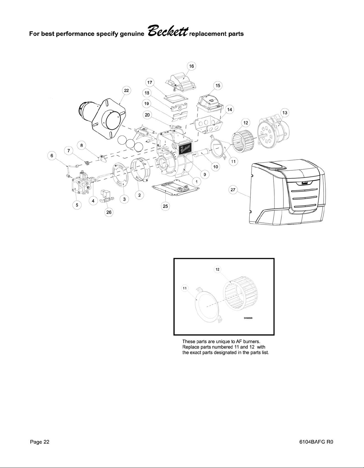
21
23
24
6
Page 24
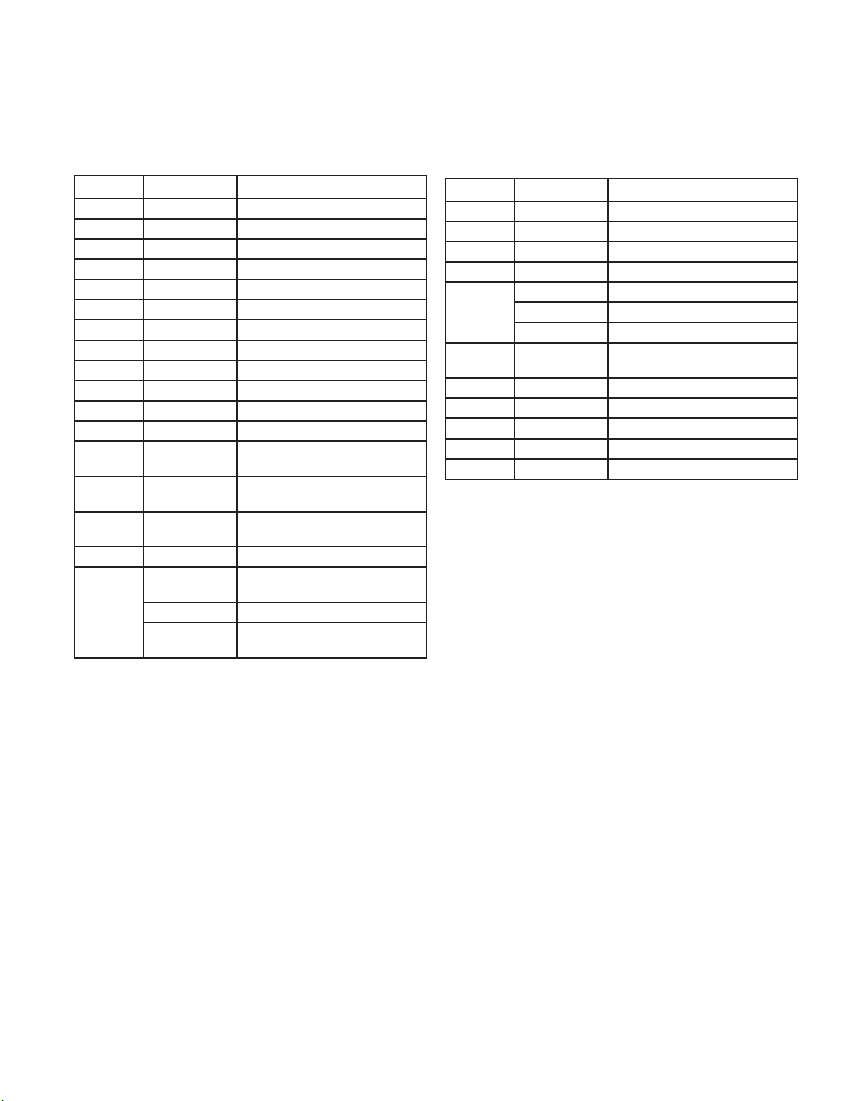
For best performance specify genuine Beckett replacement parts
# Part No. Description
1 Burner Housing Assembly
2 Specify* Air Band - Specify # of slots
3 Specify* Air Shutter - Specify # of slots
4 21807U Valve Cordset
Not Shown 21887U PD Timer Delay Cordset
5 2184404U CleanCut Pump
6 5394 Copper Oil Line - 8”
7 3666 Splined Nut
8 3493 Escutcheon (F & L1/L2 heads)
9 2139 Hole Plug
10 2454 Coupling
11 31231U (AFG)
31841U (AF)
12 2999U (AFG)
2459U (AF)
13 21805U
4189
14 5770 Electrical Box
15
7505P Replaces R7184P - Pre and Post-
Air Guide (AFG)
Air Inlet Bell (AF)
Blower Wheel (AFG)
Blower Wheel (AF)
PSC Motor
Mounting Screws
time**
# Part No. Description
16 51771U Igniter & Base Plate
17 & 18 51304 Igniter Gasket Kit
19 5880 Low Firing Rate Baffl e
20 7006U Cad Cell Detector
21
22 Specify *
23 Specify * Retention Head Assembly
24 Specify * Nozzle Line Electrode & Head Assembly
25 5685 Pedestal Kit
26 2182602U Solenoid Valve Kit (delay)
27 32395U Cover
5940 Electrode Kit - M Head up to 9”
Welded Flange
3811
Gasket Only
* Contact your Beckett Representative for part num-
ber and pricing.
** Contact your Beckett Representative for available
pre and post time settings.
6104BAFG R06 Page 23
Page 25
Limited
WARRANTY
For Residential, Commercial and Specialty Burners
The R. W. BECKETT CORPORATION (“Beckett”) warrants to persons who purchase its Beckett burners from Beckett for resale or for
incorporation into a product for resale (“Customers”) that its equipment is free from defects in material and workmanship under normal use and
service for 60 months from the date of manufacture for Residential Burners and 18 months from the date of manufacture for Commercial and
Specialty Burners. Residential burner models include: AF, AFG, AFII, NX, SF, SR and SMG. Commercial burner models include: CF375,
CF500, CF800, CF1400, CF2300A, CF2500, CF3500A, CG10, CG15, CG25 and CG50. Specialty burner models include: ADC, ADCP, ARV,
SDC and SM. The provisions of this warranty are extended to individual major burner components as follows:
a) 60 months from date of manufacture for all Beckett-branded major components, except for 12 Vdc components.
b) 18 months from date of manufacture for all non-Beckett-branded major components and Beckett branded 12 Vdc components.
Note: Normal service items found to be defective upon receipt by the customer are covered by this warranty.
THIS WARRANTY DOES NOT EXTEND TO EQUIPMENT SUBJECTED TO MISUSE, NEGLECT, OR ACCIDENT: NOR DOES THIS WARRANTY APPLY
UNLESS THE PRODUCT COVERED BY IT IS PROPERLY INSTALLED BY A QUALIFIED, COMPETENT TECHNICIAN, WHO IS LICENSED WHERE
STATE AND LOCAL CODES REQUIRE, AND WHO IS EXPERIENCED IN MAKING SUCH INSTALLATIONS, IN ACCORDANCE WITH THE LATEST
EDITION OF NFPA NO. 31 OF THE NATIONAL FIRE PROTECTION ASSOCIATION, THE LATEST EDITION OF THE NATIONAL FUEL GAS CODE (NFPA
NO. 54) AND IN ACCORDANCE WITH ALL APPLICABLE LOCAL, STATE AND NATIONAL CODES HAVING JURISDICTIONAL AUTHORITY.
Equipment, which is defective in material or workmanship and within the warranty period, may be returned for credit as follows:
Beckett Burners, Beckett-branded major components and non-Beckett-branded major components that came as original equipment on a Beckett burner
or were sold as a replacement part by Beckett should be returned, freight prepaid, to Beckett’s home office. Credit will be issued to the customer unless
the returned equipment is determined by Beckett to be out of warranty or damaged by user, in which case the equipment will be scrapped.
Note: Beckett is not responsible for any labor cost for removal and replacement of equipment.
THIS WARRANTY IS LIMITED TO THE PRECISE TERMS SET FORTH ABOVE, AND PROVIDES EXCLUSIVE REMEDIES EXPRESSLY IN LIEU OF ALL OTHER
REMEDIES, AND IN PARTICULAR THERE SHALL BE EXCLUDED THE IMPLIED WARRANTIES OF MERCHANTABILITY AND FITNESS FOR A PARTICULAR
PURPOSE. IN NO EVENT WILL BECKETT BE LIABLE FOR ANY INCIDENTAL OR CONSEQUENTIAL DAMAGE OF ANY NATURE.
authorizes any person to assume for Beckett any other liability or obligation in connection with the sale of this equipment, Beckett’s liability and Customer’s
exclusive remedy being limited to credit as set forth above.
Beckett neither assumes nor
R.W. BE C K E T T CORPORATION
P.O. Box 1289 Elyria, Ohio 44036
The Oilheat Manufacturers’ Association supports the use of low sulfur fuels as defi ned by ASTM D396, Grades No. 1 Low Sulfur
and No. 2 Low Sulfur, as the preferred heating fuel for the following reasons:
• Low sulfur fuels reduce deposits on heat exchanger surfaces, extending the service interval between cleanings.
• The reduced deposits increase the effi ciency of the appliance.
• Low sulfur fuels reduce particulate emissions.
• Low sulfur fuels reduce oxides of nitrogen emissions.
Form No. 61545 R72905
R.W. BECKETT CORPORATION
U.S.A.: P.O. Box 1289 · Elyria, Ohio 44036
www.beckettcorp.com
Canada: R.W. Beckett Canada, Ltd. · Unit #3, 430 Laird Road · Guelph, Ontario N1G 3X7
Form Number 6104 BAFG R06
Printed in U.S.A. © 2008 R.W. Beckett Corporation
01/14/09
Page 24 6104BAFG R06
 Loading...