

Page 1
88
Water & Steam Boilers – Series 2
For Gas, Light Oil, & Gas/Light Oil – Fired Burners
Burner Specification
& Data Sheet
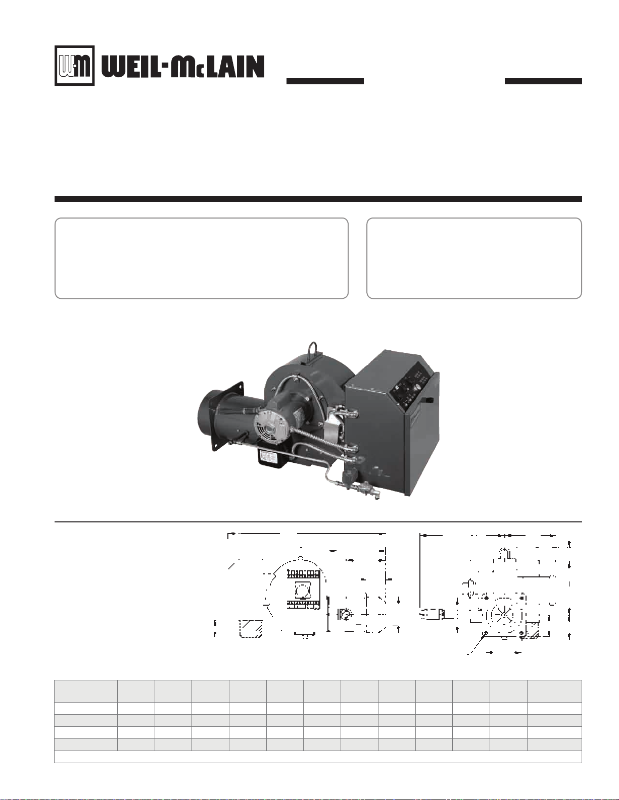
Model WCR Figure 1
A
Power Flame
Gas/Oil Burners
Model WCR
F
S
I
E
C
L
3.13
G
C
L
H
4.00
5/8 Dia., 4 holes
Note : Add .38 to “H” dim for size of opening in boiler front plate.
Burner
Model Number
WCR1 34.13 5.56 14.50 4.63 12.25 20.00 3.25 7.25 7.38 12.63 7.25 175-200
WCR2 39.13 6.13 14.00 5.25 14.00 20.00 4.00 8.75 8.50 13.38 8.50 220-300
WCR3 44.00 7.00 15.25 6.00 16.00 22.38 5.00 10.13 11.50 15.50 10.00 360-400
WCR4 50.00 7.31 17.69 7.00 18.50 28.00 6.00 12.13 14.25 19.13 12.00 500-550
A B(R) C(R) D E F* G H I S X
* Required for installation of standard control components
X
X
Part No. 550-142-029/0508
C(R)
C
L
B(R)
D
Approximate
Weight
Page 2
Weil-McLain 88 Water and Steam Boilers — Series 2 — For Gas, Light Oil, & Gas/Light Oil-Fired Burners
Burner specifications and settings
Burner dataTable 1
Boiler
Model
Number
488R
488
588
688
788
888
988R
988
1088R
1088
1188
1288
1388
1488
1588
1688R
1688
1788
1888
Burner Input
No. 2 Oil
Gph
6.9 996
7.0 1,010
9.4 1,356
11.8 1,701
14.2 2,046
16.6 2,382
17.2 2,482
18.8 2,737
20.0 2,887
21.5 3,082
23.5 3,428
26.0 3,773
28.5 4,119
31.0 4,464
33.0 4,809
34.5 4,979
35.5 5,155
38.0 5,494
40.5 5,845
Positive
Pressure
In Firebox
Gas
In. W.C.
Mbh
0.80 WCR1-G-12 WCR1-OS WCR1-GO-12 RM7897A R7184P RM7897C OO FALFS OO/FALFS
0.80 WCR1-G-12 WCR1-OS WCR1-GO-12 RM7897A R7184P RM7897C OO FALFS OO/FALFS
0.58 WCR1-G-12 WCR1-OS WCR1-GO-12 RM7897A R7184P RM7897C OO FALFS OO/FALFS
0.46 WCR2-G-15 WCR2-OAS WCR2-GO-15 RM7897A R7184P RM7897C LHO LHO LHO/LHO
0.47 WCR2-G-15 WCR2-OAS WCR2-GO-15 RM7897A R7184P RM7897C LHO LHO LHO/LHO
0.49 WCR2-G-20A WCR2-OBS WCR2-GO-20A RM7897A R7184P RM7897C LHO LHO LHO/LHO
0.50 WCR2-G-20B WCR2-OBS WCR2-GO-20B RM7897A R7184P RM7897C LHO LHO LHO/LHO 1 1 1 240/60/1
0.50 WCR2-G-20B WCR2-OBS WCR2-GO-20B RM7897C R7184P RM7897C LHO LHO LHO/LHO 1 1Z\x 1Z\x 240/60/1
0.52 WCR2-G-20B WCR2-OBS WCR2-GO-20B RM7897C RM7897A RM7897C LHO LHO LHO/LHO 1 1Z\x 1Z\x 240/60/1
0.73 WCR3-G-20 WCR3-O WCR3-GO-20 RM7897C RM7897A RM7897C LHO LHO LHO/LHO 1Z\x 2 2 240/60/1
0.53 WCR3-G-20 WCR3-O WCR3-GO-20 RM7897C RM7897A RM7897C LHO LHO LHO/LHO 1Z\x 2 2 3-Phase*
0.48 WCR3-G-20 WCR3-O WCR3-GO-20 RM7897C RM7897A RM7897C LHO LHO LHO/LHO 1Z\x 2 2 3-Phase*
0.56 WCR3-G-25 WCR3-O WCR3-GO-25 RM7897C RM7840L RM7840L LHO LHO LHO/LHO 1Z\x 2 2 3-Phase*
0.58 WCR3-G-25B WCR3-OB WCR3-GO-25B RM7840L RM7840L RM7840L LHO LHO LHO/LHO 3 3 3 3-Phase*
0.59 WCR3-G-25B WCR3-OB WCR3-GO-25B RM7840L RM7840L RM7840L LHO LHO LHO/LHO 3 3 3 3-Phase*
0.80 WCR3-G-25B WCR3-OB WCR3-GO-25B RM7840L RM7840L RM7840L LHO LHO LHO/LHO 3 3 3 3-Phase*
0.80 WCR3-G-25B WCR3-OB WCR3-GO-25B RM7840L RM7840L RM7840L LHO LHO LHO/LHO 3 3 3 3-Phase*
0.62 WCR4-G-25 WCR4-OA WCR4-GO-25 RM7840L RM7840L RM7840L LHO LHO LHO/LHO 3 5 5 3-Phase*
0.69 WCR4-G-25 WCR4-OA WCR4-GO-25 RM7840L RM7840L RM7840L LHO LHO LHO/LHO 3 5 5 3-Phase*
Gas Light
Standard
Burner Model Designation
Gas/Light Oil
Oil
* 208/60/3, 240/60/3, 480/60/3 burner motor voltage must be specified.
Standard
Combustion Control
Gas Light
Oil
Gas/Light
Oil
Standard
Control System
Gas Light
Oil
Gas/Light
Oil
Burner Motor
3450 Rpm
Gas Light
Oil
Z\x Z\x Z\x
Z\x Z\x Z\x
Z\x Z\x Z\x
Z\x C\v C\v
Z\x C\v C\v
C\v
1 1 240/60/1
Gas/
Light
Oil
Standard
Motor
Voltage
120/60/1
120/60/1
120/60/1
120/60/1
120/60/1
Notes for Table 1 and Table 2
Burner capacities listed for elevations up to 2,000 feet. For higher eleva-1.
tions, consult local Weil-McLain distributor/agent or sales office.
Light oil ratings based on No. 2 fuel oil with heating value of 140,000 2.
Btu per gallon.
Gas ratings based on natural gas with heating value of 1,000 Btu per 3.
cubic foot and specific gravity of 0.60. Gas burners for other gases are
available. Consult local Weil-McLain distributor/agent or sales office.
Boiler-burner unit to be adjusted to achieve +0.10 inches W.C. pressure 4.
at the flue collar, resulting in positive pressure in firebox as listed.
Minimum gas pressures listed are subject to variations due to job condi-5.
tions. Gas burners for other gas pressures are available. Consult local
Weil-McLain distributor/agent or sales office.
Tee pressures shown are for initial start-up. Final pressure should be 6.
determined after checking actual gas flow and combustion readings.
120/60/1 control circuit is used for all burners.7.
Control circuit transformer is available as an option.8.
Motor relay or contactor will be furnished for all units, except 488R 9.
and 488.
Airflow safety switch is standard for all gas and combination gas/light 10.
oil units.
Burners will be completely assembled and wired (except gas train) and 11.
factory test-fired.
Burners listed by Underwriters Laboratories, Inc., state of Connecti-12.
cut, Fire Marshal state of Massachusetts, city of New York MEA, and
others.
2 Part No. 550-142-029/0508
Special controls can be provided to meet other code requirements 13.
not listed. Consult your local Weil-McLain distributor/agent or sales
office.
Electric gas pilot will be furnished as standard equipment on all gas and 14.
combination gas/light oil units.
Direct spark ignition is standard for light oil units. Direct spark ignition 15.
is available as an option for combination gas/light oil units. Consult
your local Weil-McLain distributor/agent or sales office.
Gas Control Systems:16.
OO On-off operation, low fire start, high fire run. Single-position
air, adjustable opening gas valve.
LHO On-off operation, low fire start, high fire run. 488-1388:
two-position air controlled by damper arm on motorized gas
valve, fixed damper pre-purge. 1488-1888: two-position air
controlled by separate motor, open damper pre-purge.
LHL Low-high-low-off firing conditions. 488-1388: two-position
air controlled by damper arm on motorized gas valve, fixed
damper pre-purge. 1488-1888: two-position air controlled by
separate motor, open damper pre-purge.
MOD On-off operation, with proven low fire start and full modulating
firing conditions with combustion air control. Proportional
motor drives fuel metering valve and combustion air damper
according to the firing conditions. Fixed damper pre-purge on
488-1388, open damper pre-purge on 1488-1888.
Page 3

Burner Specification & Data sheet — Power Flame Gas/Oil Burners — Model WCR
Burner specifications and settings
Gas train components and flame safeguardsTable 2
Boiler
Model
Number
488R
488
588
688
788
888
988R
988
1088R
1088
1188
1288
1388
1488
1588
1688R
1688
1788
1888
Gas Pressure
Pressure
Drop Thru
Gas Train
Inches
W.C.
2.20 2.10 4.10 14.00
2.20 2.10 4.30 14.00
1.80 2.60 4.40 14.00
2.70 1.70 4.40 14.00
2.50 2.30 4.80 14.00
3.90 1.20 5.10 14.00
4.60 1.60 6.20 14.00
4.50 1.90 6.40 14.00
4.90 2.00 6.90 14.00
4.00 2.30 6.30 14.00
3.30 2.10 5.40 14.00
4.10 2.50 6.50 14.00
3.50 2.70 6.20 27.70
4.70 3.60 8.20 27.70
5.30 3.90 9.20 27.70
5.80 4.10 10.50 27.70
6.20 4.40 10.50 27.70
6.50 2.80 9.30 27.70
7.10 3.20 10.30 27.70
Required At Gas
Manifold
Pressure
Control Inlet
Inches W.C.*
Inches
W.C.*
Min Max Top Bottom
* Gas pressure shown are for standard gas train arrangement ** Primary manufacturer. For alternate nozzles, contact Power-Flame
Initial Low Fire
Damper Setting
Inches
Gph @
100
Psig
M\, M\,
M\, M\,
1 1
C\, C\,
C\, C\,
C\, C\,
C\, C\,
C\, C\,
C\, C\,
C\, C\,
C\, C\,
C\, C\,
C\, C\,
Z\v Z\v
Z\v Z\v
Z\v Z\v
Z\v Z\v
Z\v Z\v
Z\v Z\v
*** 70° spray angle standard, 60° or 80° approved and available upon request
4.50 No Delavan Solid 80° 300 295 — 100-150 B2TA-8850-4 37
4.50 No Delavan Solid 80° 300 300 — 100-150 B2TA-8850-4 37
5.50 No Delavan Solid 80° 300 300 — 100-150 B2TA-8850-4 37
7.00 No Delavan Solid 80° 300 300 183 100-150 B2TA-8851-4 43
8.50 No Delavan Solid 70° 300 300 195 100-150 B2TA-8851-4 43
9.50 No Delavan Solid 70°*** 300 300 210 100-150 B2GA-8852 43
10.00 No Monarch PLP 60° 300 300 110 80-100 B2GA-8852 47
11.00 No Delavan Solid 70°*** 300 280 135 80-100 B2GA-8852 47
12.00 No Monarch PLP 60° 300 290 140 80-100 B2GA-8852 47
16.00 Yes Del. Variflo BPS 80° 300 225 150 100-150 22R322D 105
(fixed)
14.00 Yes Del. Variflo BPS 80° 300 295 140 50-108 22R322D 105
(fixed)
16.00 Yes Del. Variflo BPS 80° 300 290 133 50-110 22R322D 105
18.00 Yes Del. Variflo BPS 80° 300 244 166 60-108 22R322D 105
20.00 Yes Del. Variflo BPS 80° 300 280 180 100-150 22R623D 105
22.00 Yes Del. Variflo BPS 60° 300 290 165 100-150 22R623D 105
22.00 Yes Del. Variflo BPS 60° 300 295 175 100-150 22R623D 135
22.00 Yes Del. Variflo BPS 60° 300 295 155 100-150 22R623D 135
24.00 Yes Hago BPS 60° 300 300 165 100-150 22R623D 135
26.00 Yes Hago BPS 60°
Bypass
Oil
System
Oil Nozzle
(One Per Unit)
Brand** Type
Spray
Angle
Pump
Capacity
Psig
300 300 175 100-150 22R623D 135
(continued)
Oil Pressures
Psig
Approximate Return
High Fire
Pump
Pressure
High Fire Low Fire
Psig
Fuel Unit Data Burner-
Motor Driven
3450 Rpm
Type
Gear
Gph
Standard Gas Control Components And Sizes In Inches
Boiler Model
Number
488R-488 1Z\v Optional Optional 1Z\v Optional Optional 1Z\v 1Z\v Optional
588 1Z\v Optional Optional 1Z\v Optional Optional 1Z\v 1Z\v Optional
688 1Z\v Optional Optional 1Z\v 1Z\v Optional * 1Z\v Optional
788 1Z\x Optional Optional 1Z\x 1Z\x Optional * 1Z\x Optional
888 2 Optional Optional 1Z\x 1Z\x Optional * 1Z\x Optional
988R 2 Optional 2 — 1Z\x Optional 1Z\x 1Z\x Optional
988-1088R 2 Standard 2 — 2 Optional 1Z\x 1Z\x Standard
1088 2 Standard 2 — 2 Optional 2 2 Standard
1188-1588 2 Standard 2 — 2 Optional 2 2 Standard
1688R-1888 2 Standard 2 — — 2 2 2 Standard
Manual Hand
Valve
Low Gas
Pressure
Switch
Light Oil Control Systems:17.
FALFS On-off operation, fixed air, reduced fuel low fire start, high fire run. Single-
position air, two-position oil.
OO On-off operation, low fire start, high fire run. Single-position air, single-position
oil.
LHO On-off operation, low fire start, high fire run. Two-position air, two-position oil.
Fixed damper pre-purge on 488-1288, open damper pre-purge on 1388-1888.
LHL Low-high-low-off firing conditions. Two-position air, two-position oil. Fixed
damper pre-purge on 488-1288. Open damper pre-purge on 1388-1888.
MOD On-off operation, with proven low fire start and full modulating firing condi-
tions. Proportional motor drives fuel metering valve and combustion air damper
according to the firing conditions. Fixed damper pre-purge on 488-1088R, open
damper pre-purge on 1088-1888.
Gas
Pressure
Regulator
* Combination operating gas valve and regulator also serves as safety gas valve.
Combination
Gas Valve And
Regulator
Motorized
Operating
Gas Valve
Motorized Operating
Gas Valve
(With Proof Of Closure)
Gas/Light Oil Control Systems:18.
OO/FALFS Combines gas and light oil characteristics
OO/OO Combines gas and light oil characteristics
LHO/LHO Combines gas and light oil characteristics
LHL/LHL Combines gas and light oil characteristics
MOD/MOD Combines gas and light oil characteristics
Safety
Gas Valve
Manual
Checking
Gas Valve
High
Gas Pressure
Switch
listed above.
listed above.
listed above. Open damper pre-purge on
1388-1888.
listed above. Open damper pre-purge on
1388-1888.
listed above. Open damper pre-purge on
1388-1888.
3Part No. 550-142-029/0508
Page 4

Weil-McLain 88 Water and Steam Boilers — Series 2 — For Gas, Light Oil, & Gas/Light Oil-Fired Burners
Burner specifications and settings
Flame safeguardsTable 3
Flame Safeguards Provided with Listed Control Systems by Code
GAS BURNERS
Boiler
Model
Number
488R-588
688-988R
988-1388
1488-1888
Boiler
Model
Number
488R
488-588
688-1088R
1088-1288
1388-1888
OO LHO LHL MOD OO LHO LHL MOD OO LHO LHL MOD OO LHO LHL MOD
RM7897A RM7897A RM7897A RM7897A RM7897A RM7897A RM7897A RM7897A RM7897A RM7897A RM7897A RM7897A RM7897C RM7897C RM7897C RM7840L
— RM7897A RM7897A RM7897A — RM7897A RM7897A RM7897A — RM7897A RM7897A RM7897A — RM7897C RM7897C RM7840L
— RM7897C RM7897C RM7840L — RM7897C RM7897C RM7840L — RM7897C RM7897C RM7840L — RM7897C RM7897C RM7840L
— RM7840L RM7840L RM7840L — RM7840L RM7840L RM7840L — RM7840L RM7840L RM7840L — RM7840L RM7840L RM7840L
FALFS LHO LHL MOD FALFS LHO LHL MOD FALFS LHO LHL MOD FALFS LHO LHL MOD
R7184P R7184P R7184P R7184P R7184P R7184P R7184P R7184P RM7897A RM7897A RM7897A RM7897A RM7897A RM7897A RM7897A RM7840L
R7184P R7184P R7184P R7184P R7184P R7184P R7184P R7184P RM7897A RM7897A RM7897A RM7897A RM7897A RM7897A RM7897A RM7840L
— R7184P R7184P R7184P — R7184P R7184P R7184P — RM7897A RM7897A RM7897A — RM7897A RM7897A RM7840L
— RM7897A RM7897A RM7840L — RM7897A RM7897A RM7840L — RM7897A RM7897A RM7840L — RM7897A RM7897A RM7840L
— RM7840L RM7840L RM7840L — RM7840L RM7840L RM7840L — RM7840L RM7840L RM7840L — RM7840L RM7840L RM7840L
UL FM CSD-1 IRI
LIGHT OIL BURNERS
UL FM CSD-1 IRI
COMBINATION GAS/OIL BURNERS
(continued)
Boiler
Model
Number
488R-588
688-988R
988-1288
1388-1888
OO/FALFS LHO LHL MOD OO/FALFS LHO LHL MOD OO/FALFS LHO LHL MOD OO/FALFS LHO LHL MOD
RM7897C RM7897C RM7897C RM7897C RM7897C RM7897C RM7897C RM7897C RM7897C RM7897C RM7897C RM7897C RM7897C RM7897C RM7897C RM7840L
— RM7897C RM7897C RM7897C — RM7897C RM7897C RM7897C — RM7897C RM7897C RM7897C — RM7897C RM7897C RM7840L
— RM7897C RM7897C RM7840L — RM7897C RM7897C RM7840L — RM7897C RM7897C RM7840L — RM7897C RM7897C RM7840L
— RM7840L RM7840L RM7840L — RM7840L RM7840L RM7840L — RM7840L RM7840L RM7840L — RM7840L RM7840L RM7840L
UL FM CSD-1 IRI
Notes for Table 3
Combustion Controls:1.
R7184P Uses cadmium cell for flame detector to monitor oil burner flame, also furnishes intermittent ignition.
RM7897A, RM7897C Uses ultraviolet electronic flame detector to monitor gas or oil burner flame and provides pre-purge programming. “A” models
RM7840L, E110/EPD170 Monitors the oil or gas burner flame, provides pre-purge and post-purge programming, provides switching necessary to allow
RM7800L, E110/EP160 Monitors the oil or gas burner flame with digital readout control system, provides pre-purge and post-purge programming,
provide intermittent pilot; “C” models provide interrupted pilot and RUN/TEST switch. RM7897 provides same as above with
post-purge.
firing rate motor to be driven to both low fire and high fire positions, prevents start-up if pre-ignition interlocks are open and
has low fire start proving circuit. In the event pre-ignition interlock circuit or running interlock circuit does not “prove”, system
will lock out on safety. Ultraviolet sensitive electronic flame detector is standard with infrared detector available.
provides switching necessary to allow firing rate motor to be driven to both low fire and high fire position, prevents start-up
if pre-ignition interlocks are open and has low fire start proving circuit. In the event pre-ignition interlock circuit or running
interlock circuit does not “prove”, system will lock out on safety. Ultraviolet sensitive electronic flame detector is standard with
infrared detector available.
4 Part No. 550-142-029/0508
 Loading...