

Weil-McLain EVG 70, EVG 155, EVG 110 User Manual
CONDENSING GAS BOILER
70/110/155
®
Boiler Manual
• Installation
• Startup
• Maintenance
• Parts
This manual must only be used by a qualifi ed heating installer/service technician. Read all instructions, including this manual and
all other information shipped with the boiler, before installing. Perform steps in the order given. Failure to comply could result in
severe personal injury, death or substantial property damage.
Part number 550-100-191/0917
®
Contents
gas-fired water boiler — 70/110/155 Boiler Manual
The Evergreen® Gas-fi red water boilers . . . . . . . . . . . . 2
Please read before proceeding . . . . . . . . . . . . . . . . 7
Boiler location . . . . . . . . . . . . . . . . . . . . . . . . . 8
Prepare boiler location . . . . . . . . . . . . . . . . . . . . 10
Wall-mounting the boiler. . . . . . . . . . . . . . . . . . . 10
Boiler hydrostatic test . . . . . . . . . . . . . . . . . . . . 13
Converting boiler to propane — EVG 70 . . . . . . . . . . . 15
Converting boiler to propane — EVG 110 . . . . . . . . . . 17
Converting boiler to propane — EVG 155 . . . . . . . . . . 19
Gas piping — sizing gas lines . . . . . . . . . . . . . . . . 21
Venting/air piping — general . . . . . . . . . . . . . . . . 22
Commonwealth of Massachusetts installations . . . . . . 25
Vent termination requirements . . . . . . . . . . . . . . . 26
Boiler room air openings . . . . . . . . . . . . . . . . . . . 27
DIRECT VENT — Sidewall with separate pipes . . . . . . . 28
DIRECT VENT — Sidewall concentric . . . . . . . . . . . . 30
DIRECT VENT — Sidewall with W-M vent/air plate . . . . . 32
DIRECT VENT — Vertical with separate pipes. . . . . . . . 34
DIRECT VENT — Vertical concentric. . . . . . . . . . . . . 36
Concentric termination, typical (sidewall or vertical). . . . 38
Vent and air piping and boiler connections . . . . . . . . . 39
Install water piping . . . . . . . . . . . . . . . . . . . . . 40
Direct Connect System Piping - Single Boiler System . . . 41
Verify the application will work. . . . . . . . . . . . . . . . . . 41
Expansion tank location. . . . . . . . . . . . . . . . . . . . . . 41
Diaphragm- or bladder-type tank. . . . . . . . . . . . . . . . . 41
Closed-type expansion tank . . . . . . . . . . . . . . . . . . . 42
System water piping methods . . . . . . . . . . . . . . . . . . 43
Install relief valve . . . . . . . . . . . . . . . . . . . . . . . . . 43
ZONE VALVE zoning – direct connection . . . . . . . . . . . . . 44
Primary/Secondary System Piping - Single Boiler System See
Advanced Manual for Multiple Boiler Systems . . . . . . . 45
Expansion tank location. . . . . . . . . . . . . . . . . . . . . . 45
Diaphragm- or bladder-type tank. . . . . . . . . . . . . . . . . 45
Closed-type expansion tank . . . . . . . . . . . . . . . . . . . 46
System water piping methods . . . . . . . . . . . . . . . . . . 47
Install relief valve . . . . . . . . . . . . . . . . . . . . . . . . . 48
ZONE VALVE zoning – primary/secondary . . . . . . . . . . . . . . . 49
CIRCULATOR zoning – primary/secondary . . . . . . . . . . . . . . 50
CIRCULATOR zoning – primary/secondary multi. temp. zone . . . . 51
Install condensate line. . . . . . . . . . . . . . . . . . . . . . . . 52
Gas piping . . . . . . . . . . . . . . . . . . . . . . . . . . 53
DO NOT SERVICE THE BOILER
WITHOUT AN Evergreen®
MAINTENANCE KIT AVAILABLE
The maintenance kit includes components that may have
to be replaced when accessing or disassembling parts of the
boiler. Failure to replace damaged components and to use
only the parts specifi cally intended for the boiler can result in
severe personal injury, death or substantial property damage.
See Figure 110, page 127 for part number.
Field wiring . . . . . . . . . . . . . . . . . . . . . . . . . . 54
Wiring diagram — schematic . . . . . . . . . . . . . . . . 62
Wiring diagram — ladder . . . . . . . . . . . . . . . . . . 63
Zoning with the EVG Control . . . . . . . . . . . . . . . . . 64
Evergreen control operation . . . . . . . . . . . . . . . . . 66
EVG control settings menus . . . . . . . . . . . . . . . . . 70
EXPRESS SETUP — Example A . . . . . . . . . . . . . . . 72
EXPRESS SETUP — Example B . . . . . . . . . . . . . . . 74
EXPRESS SETUP — Example C . . . . . . . . . . . . . . . 76
Available control settings and system presets . . . . . . . 78
CONTRACTOR menus . . . . . . . . . . . . . . . . . . . . . 79
BOILER SETTINGS menu, BASIC mode . . . . . . . . . . . . 80
PRIORITY 1, 2, 3 menus, BASIC mode . . . . . . . . . . . . 81
ASSIGN INPUTS menu, BASIC mode . . . . . . . . . . . . . 82
DIAGNOSTIC menu . . . . . . . . . . . . . . . . . . . . . . 84
MAINTENANCE, DATE AND TIME menus . . . . . . . . . . . 89
Startup — fi ll the system . . . . . . . . . . . . . . . . . . 91
Startup — fi nal checks . . . . . . . . . . . . . . . . . . . 93
Check-out/startup verifi cation. . . . . . . . . . . . . . . . 99
Annual startup and general maintenance . . . . . . . . . . 100
Annual startup . . . . . . . . . . . . . . . . . . . . . . . . 101
Troubleshooting . . . . . . . . . . . . . . . . . . . . . . . 107
Maintenance . . . . . . . . . . . . . . . . . . . . . . . . . 115
Cleaning heat exchanger fl ue side, 70. . . . . . . . . . . . 117
Cleaning heat exchanger fl ue side, 110 . . . . . . . . . . . 120
Cleaning heat exchanger fl ue side, 155 . . . . . . . . . . . 123
Replacement parts . . . . . . . . . . . . . . . . . . . . . . 126
Dimensions . . . . . . . . . . . . . . . . . . . . . . . . . . 138
Ratings — Evergreen® boilers . . . . . . . . . . . . . . . 139
Installation and Service Certifi cate . . . . . . . . . . . . . 141
Evergreen® Gas Boiler Data Collection Sheet . . . . . . . 144
Hazard defi nitions
The following defi ned terms are used throughout this manual to bring attention to the presence of hazards of various risk levels
or to important information concerning the life of the product.
Indicates presence of hazards that will cause severe
personal injury, death or substantial property
damage.
Indicates presence of hazards that can cause severe
personal injury, death or substantial property
damage.
2
Indicates presence of hazards that will or can
cause minor personal injury or property damage.
Indicates special instructions on installation,
operation or maintenance that are important
but not related to personal injury or property
damage.
Part number 550-100-191/0917

®
gas-fired water boiler — 70/110/155 Boiler Manual
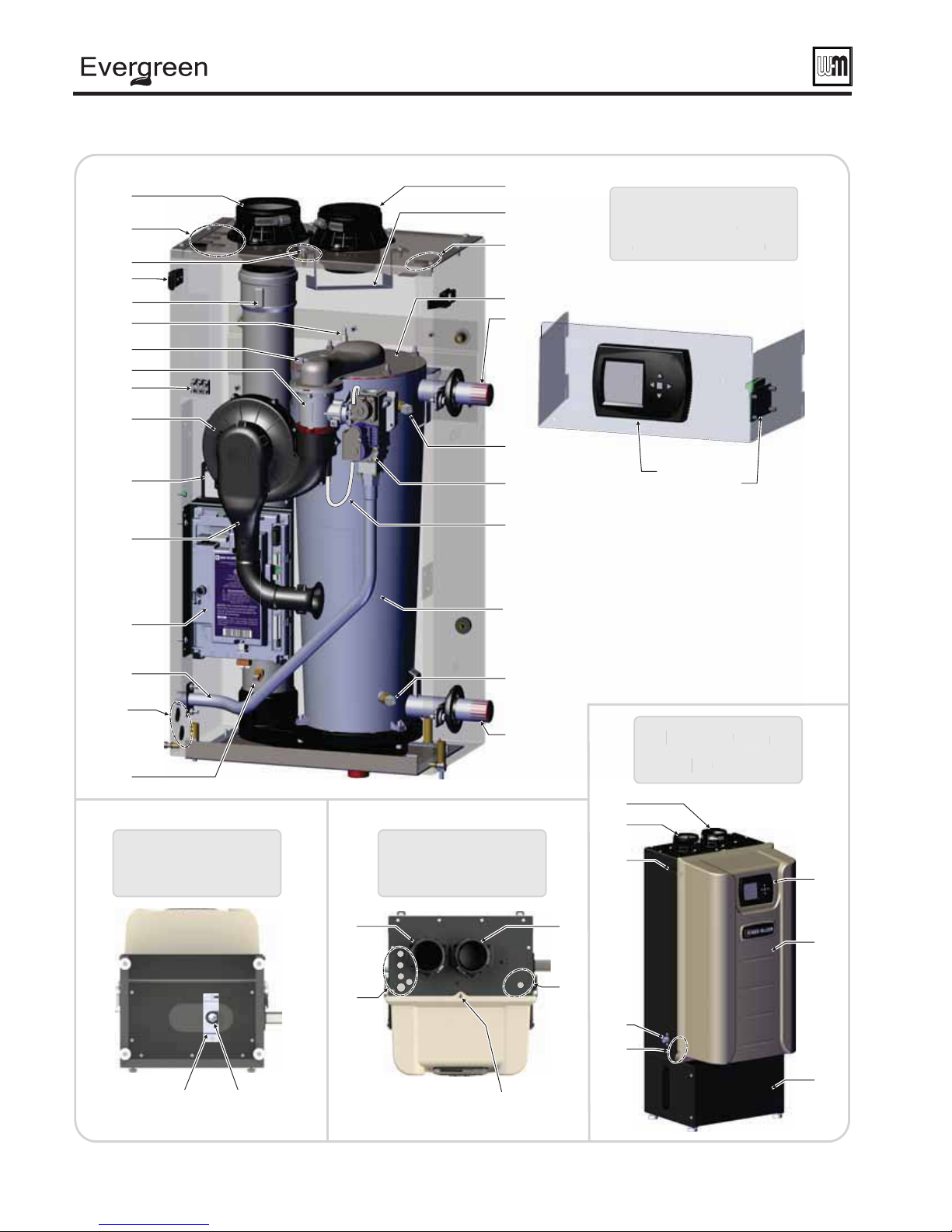
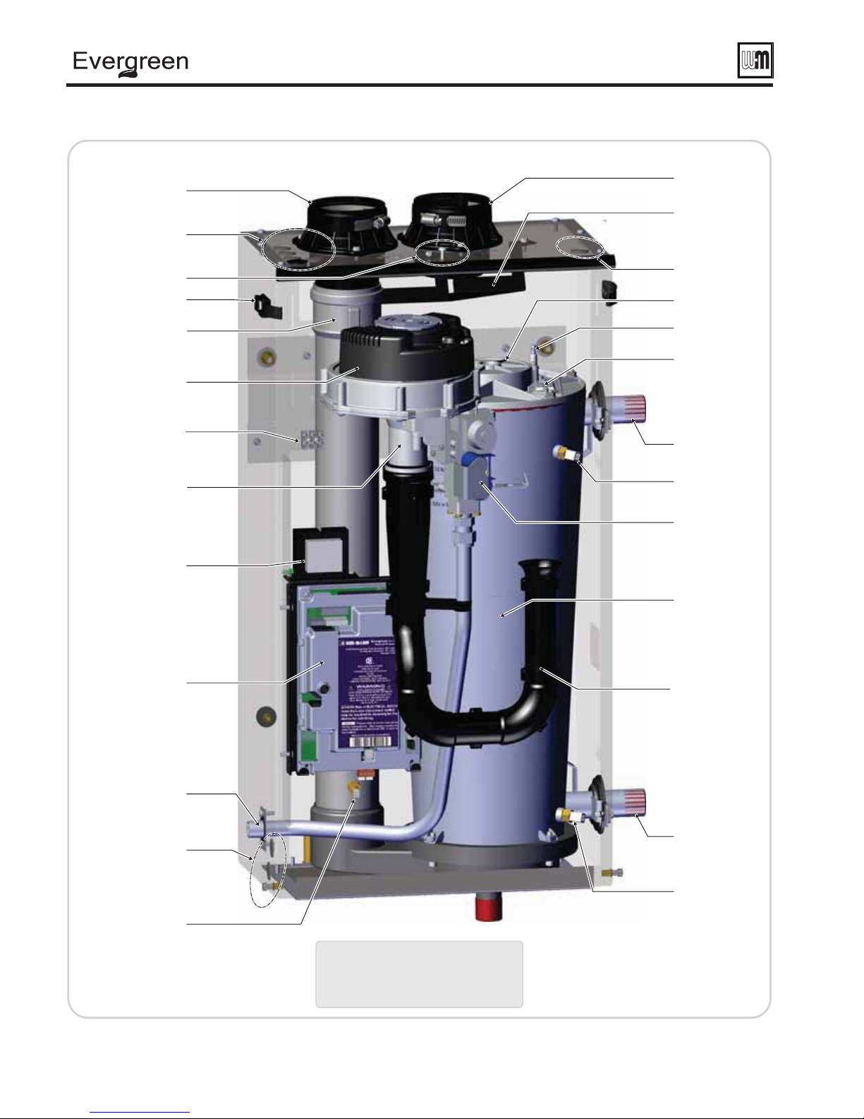
The Evergreen® Gas-fi red water boilers
1. Stainless steel fi retube heat exchanger
2. Heat exchanger access cover/burner mounting plate
3. Blower
The advanced blower design and air inlet silencer on Evergreen® boilers
result in very quiet operation.
Air enters the boiler enclosure through the air intake adapter (Item 19),
fl ows through the enclosure, enters the air inlet silencer (Item 5), then enters
the venturi (Item 6) where it mixes with gas before entering the blower. The
blower pulls air through these components and then pushes it through the
cover plate to the burner (Item 12).
4. Gas valve
The automatic gas valve references the pressure in the cabinet and allows gas to
fl ow when the control (Item 16) applies power. A manual gas shut off valve is
shipped loose with the boiler. It allows shutting off the gas supply for servicing
or shut down. See instructions in this manual for manual gas valve installation.
5. Air inlet silencer
The horn-shaped air inlet silencer signifi cantly reduces fan noise, providing
exceptionally quiet operation.
6. Venturi
When air fl ows through the venturi, a negative pressure is created. This causes
gas to fl ow from the gas valve into the venturi, where it is mixed with the air.
The gas/air mixture then continues into the blower.
7. Supply water temperature dual sensor
This dual sensor monitors boiler outlet water temperature. The control adjusts
boiler fi ring rate so the outlet water temperature is correct, based on the
calculated (if outdoor reset used — see page 139 ) or fi xed target temperature.
8. Return water temperature sensor
This sensor monitors return water temperature to the boiler. The control
reduces or increases boiler input, depending on how close the return water
temperature is to the outlet water temperature.
9. Electronic display & buttons
The electronic display is used to confi gure boiler settings and monitor
boiler operation. The buttons allow changing display mode, selecting and
adjusting control settings, and resetting the control after lockout.
10. Flue adapter (fi ts 3" PVC)
11. Flue pipe
12. Burner (not shown)
Made with high-grade stainless steel construction, the burner uses premixed air and gas. The burner and control provide modulating fi ring.
13. Water outlet pipe (system supply)
14. Water inlet pipe (system return)
15. Gas line
This stainless steel fl exible gas line connects the incoming gas line to the
gas valve.
The gas line has a ½” NPT connection for installation.
16. Control module (see discussion upper right)
17. Communication Board
The communication board provides boiler-to-boiler communication and
Building Management System (BMS) interface.
18. Boiler circulator terminal block
19. Air intake adapter (fi ts 3" PVC)
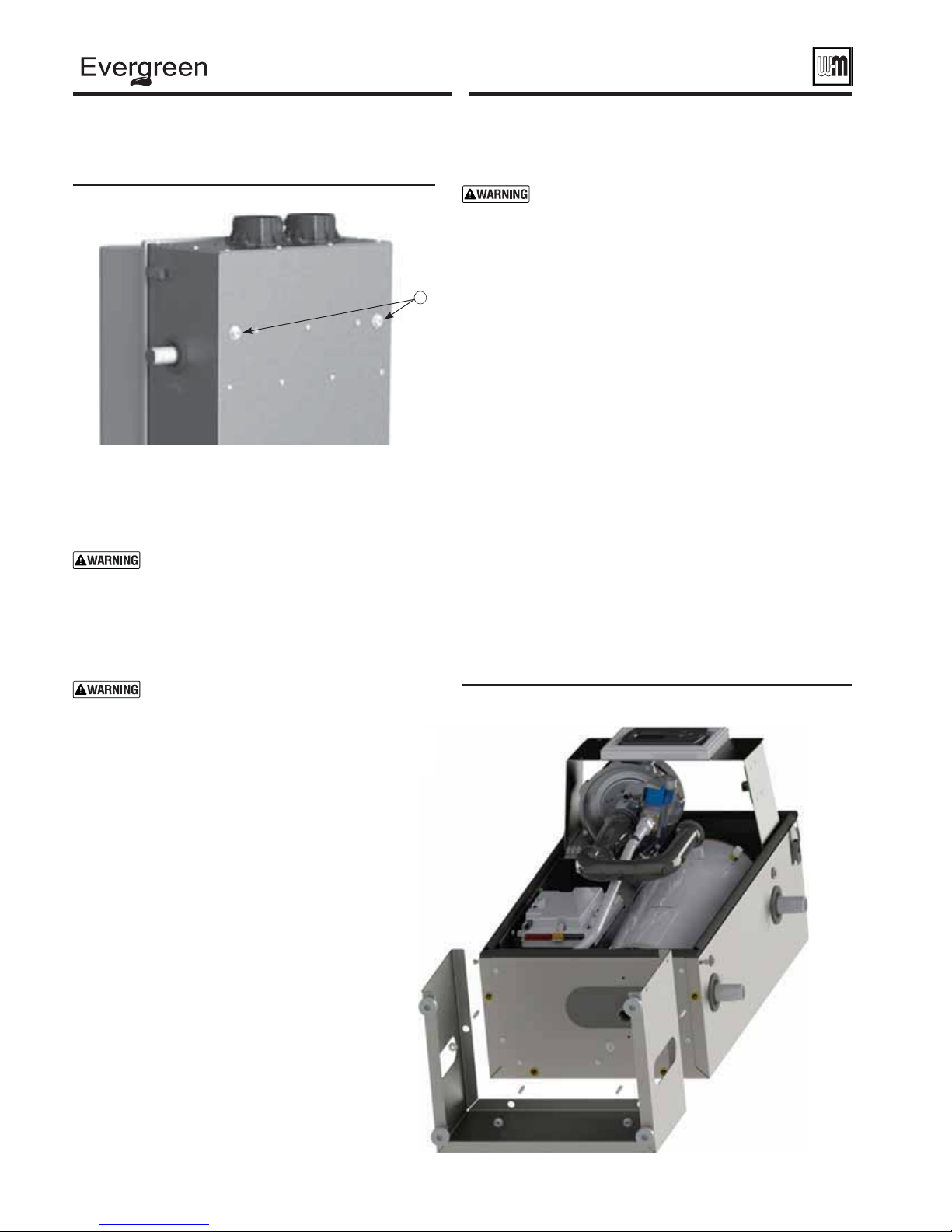
20a. Electrical entrances (line voltage)
The top left side knockouts are designated for line voltage wiring only.
Ensure all wiring entrances are sealed.
20b. Electrical entrances (low voltage)
The bottom left side knockouts are designated for low voltage wiring
only. Ensure all wiring entrances are sealed.
20c. Electrical entrance (multiple boiler communication)
The top right knockout (1) is designated for multiple boiler
communication and BMS wiring. Ensure all wiring entrances are sealed.
21. Boiler drain valve (not shown)
Shipped loose for fi eld piping. Pipe drain valve on reducing tee at the lowest
point of return piping to boiler. See instructions, page 14 in this manual.
22. Condensate trap nozzle
The outlet at the bottom of the condensate collection dish. This is where
condensate is discharged from the boiler. The condensate trap assembly
attaches here.
Part number 550-100-191/0917
Evergreen® control overview
• The Evergreen® control can operate a single boiler or coordinate
with other Evergreen® boilers in a multiple boiler system.
• Control inputs and outputs allow operation of multiple heating
circuits (space heating and DHW, for example).
• Up to three priority levels can be set, providing automatic switchover on demand.
• This manual provides quick set-up information for single boiler
installations.
• The Advanced Manual, also supplied with the boiler, provides
instructions for setting up multiple-boiler systems and for using
advanced options for single boilers.
Evergreen® control operation
• The control responds to signals from the room thermostats, DHW
aquastats (if used), boiler sensors (boiler return, boiler supply, fl ue
temperature), outdoor temperature and system sensors, if used.
• The control automatically adjusts blower speed (and gas fl ow
rate) to match boiler output to space heating and/or DHW
heating demand.
• The default control settings provide for three space heating zones.
The control can be easily set up for operation with a DHW zone,
with or without domestic priority.
Evergreen® control WIZARD
• The control setup Wizard is available from the BOILER
SETTINGS menu that appears during initial startup.
• The Wizard leads through a step-by-step setup procedure
designed for the application chosen.
• Context-sensitive help is available to explain the purpose of key
setup items.
23. Flue gas condensate drain trap assembly and bracket
The condensate trap assembly and bracket are fi eld-installed, condensate
drain trap is connected to the condensate trap nozzle as shown in this
manual.
24. Jacket door
The jacket door is sealed to the boiler assembly around its entire perimeter.
25. Front door latches
Two (2) latches secure the door in place.
26. Door retention screw
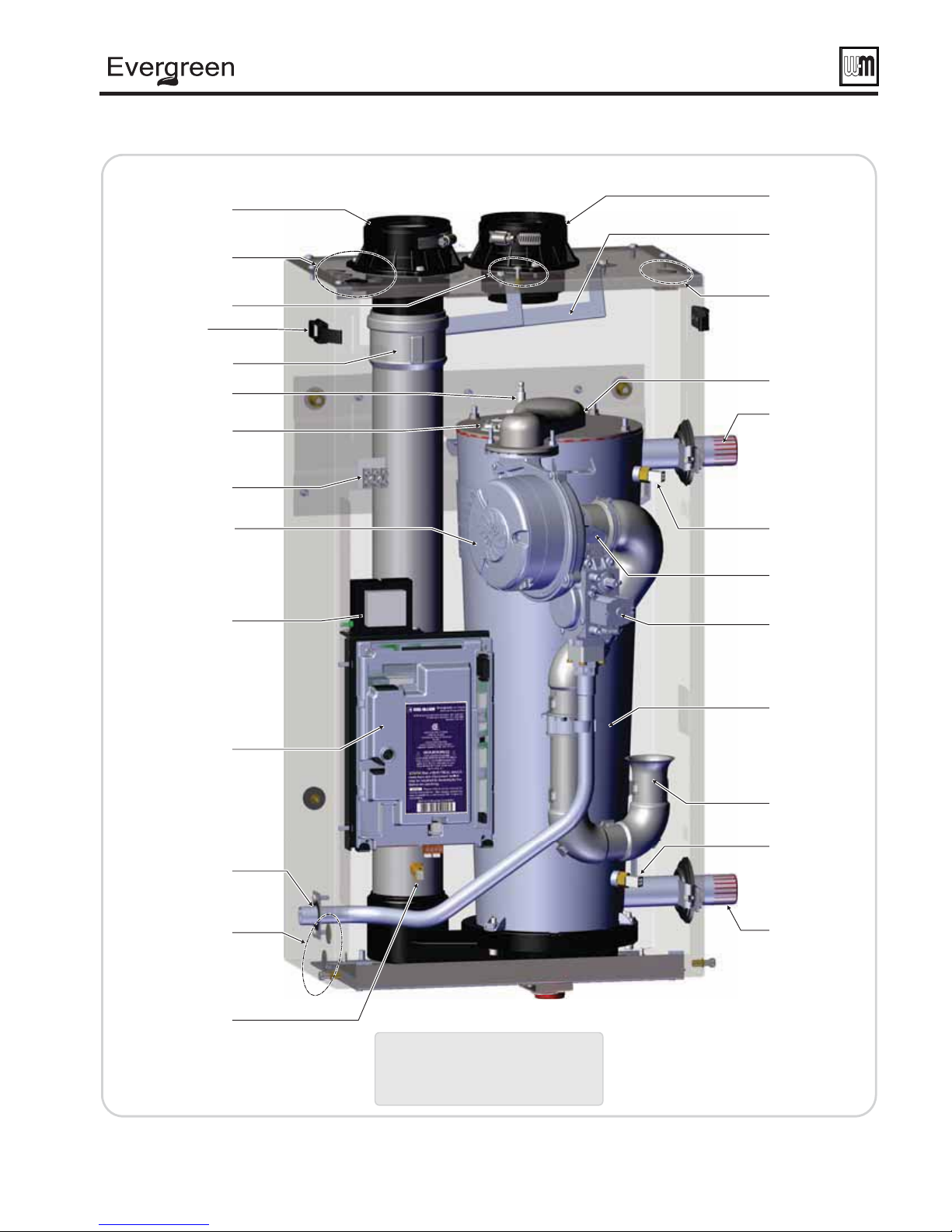
27. Ignition electrode/fl ame sensor
The burner fl ame is ignited by applying a high voltage to the ignition
electrode. This causes a spark (from electrode to ground). After ignition,
the electrode measures fl ame signal.
28. Flame inspection window
The quartz glass window provides a view of the burner surface, the fl ame,
and the ignition electrode.
29. Flue gas dual sensor
This dual sensor monitors the fl ue gas exit temperature. The Evergre en®
control will shut down the boiler if fl ue gas temperature gets too hot.
This protects the fl ue pipe and the heat exchanger from overheating.
30. Gas valve reference hose (EVG-70 only)
This rubber line connects the gas valve diaphragm reference chamber to
the venturi intake to insure the valve senses the correct reference pressure.
31. Transformer
The 120V/24V transformer provides 24V to low voltage control circuitry.
Do NOT splice wiring into transformer.
32. Air baffl e
The air baffle protects internal boiler components by diverting any
incoming moisture or debris away from critical components. It must be
temporarily removed while servicing the heat exchanger.
33. Floor stand assembly
The provided stand allows for the Evergreen® boiler to be either wall
hung or fl oor standing.
3
C
D
B
J
O
U
C
D
B
®
gas-fired water boiler — 70/110/155 Boiler Manual
The EVG-70 Gas-fi red water boilers
B
D
&7(
*OUFSJPS
OUFS
TPNFDPNQPOFOUTPNJUUFEGPSDMBSJUZ
TPNFDPNQPOFOUTPNJUUFEGPSDMBSJUZ
C
&WFSHSFFO
#PUUPN
&WFSHSFFO
5PQ
&WFSHSFFO
&WFSHS
'SPOU
S
O
(9*
4
B
D
C
Part number 550-100-191/0917
C
D
B
®
gas-fired water boiler — 70/110/155 Boiler Manual
The EVG-110 Gas-fi red water boilers
B
D
C
&7(
*OUFSJPS
TPNFDPNQPOFOUTPNJUUFEGPSDMBSJUZ
(9*
Part number 550-100-191/0917
5
C
D
B
®
gas-fired water boiler — 70/110/155 Boiler Manual
The EVG-155 Gas-fi red water boilers
B
D
6
C
&7(
*OUFSJPS
TPNFDPNQPOFOUTPNJUUFEGPSDMBSJUZ
(9*
Part number 550-100-191/0917
®
gas-fired water boiler — 70/110/155 Boiler Manual
Please read before proceeding
Installer— Read all instructions, including this
manual and all other information shipped with the
boiler, before installing. Perform steps in the order given.
User — This manual is for use only by a qualifi ed
User — Have this boiler serviced/inspected by a
Failure to comply with the above could result in severe
heating installer/service technician. Refer to User’s
Information Manual for your reference.
qualifi ed service technician, at least annually.
personal injury, death or substantial property damage.
If any part of a boiler, burner or its controls has
been sprayed with or submerged under water,
either partially or fully, DO NOT attempt to
operate the boiler until the boiler has been either
replaced or completely repaired, inspected, and
you are sure that the boiler and all components
are in good condition and fully reliable.
Otherwise, by operating this boiler, you will
cause a fi re or explosion hazard, and an electrical
shock hazard, leading to serious injury, death, or
substantial property damage. See the instructions
at right.
Failure to adhere to the guidelines below can result in severe personal injury, death or substantial property damage.
EXPANSION TANK
• Relieve pressure from the system
before isolating the expansion tank.
When servicing boiler —
• To avoid electric shock, disconnect all
electrical supplies to the boiler before
performing maintenance.
• To avoid severe burns, allow boiler to cool
before performing maintenance.
• This boiler contains ceramic fiber
and fiberglass materials. Refer to the
WARNING and instructions on page 101 .
Boiler operation —
• Do not block fl ow of combustion or
ventilation air to boiler.
• Should overheating occur or gas supply
fail to shut off, do not turn off or
disconnect electrical supply to circulator.
Instead, shut off the gas supply at a
location external to the appliance.
Combustion air —
• DO NOT install combustion air intake
where there is a risk of combustion air
contamination.
Carbon monoxide detector —
• A carbon monoxide detector that is
wired on the same electrical circuit as
the boiler is strongly recommended.
SURGE PROTECTOR —
• Provide surge protection in the boiler
power supply. This will reduce the
possibility of damage to the boiler
control.
Boiler water —
• The Evergreen® heat exchanger is made
of stainless steel, and requires that
system water chemistry be within the
limits in this manual. Use the Sentinel
X100 inhibitor supplied with boiler.
ADDITIONAL CHEMICAL TREATMENT
MAY BE NECESSARY
details.
• Thoroughly fl ush the system (BEFORE
connecting boiler) to remove sediment.
The high-effi ciency heat exchanger can
be damaged by build-up or corrosion
due to sediment.
• Do not use petroleum-based cleaning
or sealing compounds in boiler system.
Gaskets and seals in the system may be
damaged. This can result in substantial
property damage.
• Continual fresh make-up water will
reduce boiler life. Mineral buildup in
eat exchanger reduces heat transfer,
overheats the stainless steel heat
exchanger, and causes failure. Addition
of oxygen carried in by make-up water
can cause internal corrosion. Leaks in
Write in the CP number in the space provided on the
Installation certifi cate on page 141 if not already shown.
When calling or writing about the boiler— Please
Consider piping and installation when determining
have the boiler model number from the boiler rating
label and the CP number from the boiler jacket.
boiler location.
Any claims for damage or shortage in shipment
must be fi led immediately against the transportation
company by the consignee.
Saltwater Damage — The exposure of boiler components to
saltwater can have both immediate and long-term effects. While
the immediate effects of saltwater damage are similar to those of
freshwater (shorting out of electrical components, washing out of
critical lubricants, etc.), the salt and other contaminants left behind can
lead to longer term issues after the water is gone due to the conductive
and corrosive nature of the salt residue. Therefore, Weil-McLain
equipment contaminated with saltwater or polluted water will
no longer be covered under warranty and should be replaced.
Electrical Damage — If any electrical component or wiring
came into contact with water, or was suspected to have come into
contact with water, replace the boiler with a new Weil-McLain boiler.
boiler or piping must be repaired at once
to prevent make-up water. Use this boiler
ONLY in a closed-loop system.
• Do not add cold water to a hot boiler.
Thermal shock can cause the heat
exchanger to crack.
Freeze protection fl uids —
• NEVER use automotive or standard
glycol antifreeze. Use only freezeprotection fluids made for hydronic
systems. Follow all guidelines given by
. See page 91 for
the antifreeze manufacturer. Thoroughly
clean and fl ush any replacement boiler
system that has used glycol before
installing the new boiler. Use only the
products listed by Weil-McLain for use
with this boiler. See page 92 for details.
Frozen Water Damage
Hazard
Residences or buildings that are unattended
in severely cold weather, boiler system
components failures, power outages,
or other electrical system failures could
result in frozen plumbing and water
damage in a matter of hours. For your
protection, take preventative actions such
as having a security system installed that
operates during power outages, senses
low temperature, and initiates an effective
action. Consult with your boiler contractor
or a home security agency.
Commonwealth of
Massachusetts
When the boiler is installed within the Commonwealth of Massachusetts:
• This product must be installed by a licensed plumber or gas fi tter.
• If antifreeze is used, a reduced pressure back-fl ow preventer device shall be used.
• Sidewall vent air installations — see instruction on page 25 .
Part number 550-100-191/0917
7

®
gas-fired water boiler — 70/110/155 Boiler Manual
Boiler location
Installations must comply with:
• Local, state, provincial, and national codes, laws,
regulations and ordinances.
• National Fuel Gas Code, ANSI Z223.1/NFPA 54 - latest
edition.
• National Electrical Code ANSI/NFPA 70 – latest edition.
Electrical installation and grounding must be in
accordance with CSA C22.1, Part 1, Canadian Electrical
Code, and/or local codes.
• For Canada only: CAN/CSA B149.1, Natural Gas and
Propane Installation Code, and any local codes.
• Where required by the authority having jurisdiction, the
installation must conform to the Standard for Controls
and Safety Devices for Automatically Fired Boilers,
ANSI/ASME CSD-1.
The Evergreen® boiler gas manifold
and controls met safe lighting and other
performance criteria when boiler underwent
tests specifi ed in ANSI Z21.13 — latest
edition.
Before locating the boiler, check:
®
1. The Evergreen
mounted.
2. Wall construction — If the boiler is wall-mounted,
make sure the wall construction is suitable to carry
the weight of the boiler and components. See page 10
for instructions.
3. The boiler is suitable for INDOOR installation
4. Check for nearby connection to:
• System water piping • Venting connections
• Gas supply piping • Electrical power
• Condensate drain
5. Check area around boiler. Remove any combustible
materials, gasoline and other fl ammable liquids.
Failure to keep boiler area clear and free of
6. The Evergreen
control system components are protected from dripping
or spraying water or rain during operation or service.
7. If new boiler will replace existing boiler, check for and
correct system problems, such as:
• Sediment or corrosion in system piping — clean and
fl ush piping BEFORE connecting the new boiler.
See page 91 .
• System leaks causing oxygen corrosion or heat ex-
changer cracks from hard water deposits.
• Incorrectly-sized expansion tank.
• Lack of freeze protection in boiler water causing
system and boiler to freeze and leak.
boiler
can be fl oor-standing or wall
only.
combustible materials, gasoline and other
fl ammable liquids and vapors can result in
severe personal injury, death or substantial
property damage.
®
boiler must be installed so that gas
Residential garage installation
Precautions
1. Take the following special precautions when installing the boiler in
a residential garage. If the boiler is located in a residential garage:
• Mount the boiler with its burner and igniter are at least
18 inches above the fl oor. Follow the National Fuel Gas Code,
ANSI Z223.1 for U. S. installations, or Natural Gas and Propane Installation Code, CSA B149.1 and B149.2 for Canadian
installations.
• Locate or protect the boiler so it cannot be damaged by a
moving vehicle.
• Ensure that the installation complies with all applicable codes.
• Prevent boiler water and condensate from freezing.
Provide air openings to room
Evergreen® boiler alone in boiler room
1. No air ventilation openings into boiler room are needed if
clearances around boiler are at least equal to the SERVICE
clearances shown in Figure 1, page 9 .
2. For spaces that DO NOT supply the minimum service clearances,
provide two openings as shown in Figure 1, page 9 . Each opening
must provide 1 square inch free area per 1,000 Btuh of boiler input.
The space must be provided with combustion/
ventilation air openings correctly sized for all
appliances located in the same space as the Evergreen®
boiler.
Reinstall boiler jacket door after servicing. The boiler
Failure to comply with the above warnings could
jacket door must be securely fastened to the boiler to
prevent boiler from drawing air from inside the boiler
room. This is particularly important if the boiler is
located in the same room as other appliances.
result in severe personal injury, death or substantial
property damage.
Evergreen® boiler in same space with other gas or
oil-fi red appliances
1. Follow the sizing requirements shown in Figure 25, page 27 .
Vent and air piping
1. The EVG boiler requires a special vent system, designed for
pressurized venting. The boilers are rated ANSI Z21.13 Category
IV (pressurized vent, likely to condense in the vent). See
instructions beginning on page 22 .
2. You must also install air piping from outside to the boiler air
intake adapter. The resultant installation is categorized as direct
vent (sealed combustion). Note prevention of combustion air
contamination on
3. Vent and air must terminate near one another unless otherwise
specifi ed in this manual. Vent and air piping may be routed
vertically through the roof or out a side wall, following the options
given in this manual. You may use any of the vent/air piping
methods covered in this manual. Do not attempt to install the
EVG boiler using any other means.
4. Be sure to locate the boiler such that the vent and air piping can be
routed through the building and properly terminated. The vent/air
piping lengths, routing and termination method must all comply
with the methods and limits in instructions beginning on
page 22 when considering vent/air termination.
page 22 .
8
Part number 550-100-191/0917
®
gas-fired water boiler — 70/110/155 Boiler Manual
Boiler location (continued)
Provide clearances for service
access — RECOMMENDED
1. See Figure 1 for recommended service clearances.
2. If you do not provide minimum service clearances
shown, it might not be possible to service the boiler
without removing it from the space.
3. Clearance D, Figure 1 allows for the installation of
piping as shown in Figure 8, page 12 plus a close nipple
and elbow.
Closet or small-enclosure installations
which do not provide at least these
recommended clearances require the
specially-sized and placed air openings
shown in Figure 2
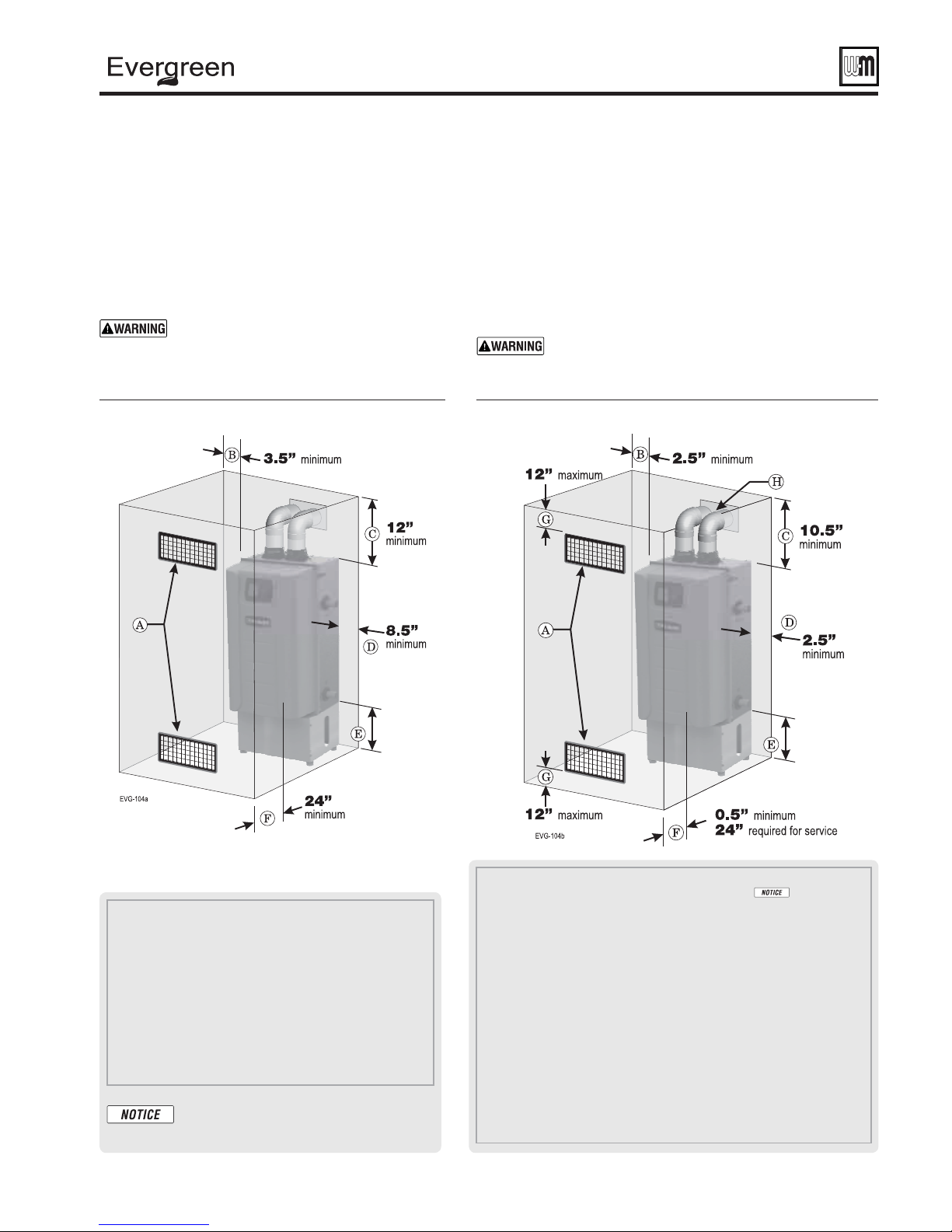
Figure 1 RECOMMENDED service clearances
(
all dimensions are in inches)
.
Provide clearances from combustible
materials — REQUIRED
1. See Figure 2 for REQUIRED minimum clearances. ALL
installation must provide at least these minimums.
2. Hot water pipes — at least ½ inches from combustible materials.
3. Vent pipe — at least
4. Clearance D, Figure 2 allows for the installation of a reducer
bushing (155 only) and elbow. Other piping may require
additional clearance.
5. See Figure 1 for service clearance minimums.
Closet or small-enclosure installations which do
not provide at least the recommended service
clearances shown in
sized and placed air openings shown in Figure 2
Figure 2 REQUIRED minimum clearances
(
all dimensions are in inches)
3/16 inches from combustible materials.
Figure 1 require the specially-
.
A Provide combustion air/ventilation openings per
Figure 25, page 27 or as otherwise directed in this manual or
by applicable codes. NOTE: If the installation does not provide
the minimum clearances in this illustration, then the enclosure
must have air openings located and sized per Figure 2 .
B Left side service clearance = 3.5 inches minimum.
C Service clearance above top of boiler = 12 inches minimum.
D Right side service clearance = 8.5 inches minimum.
E Service clearance below the boiler = 12 inches minimum for
wall hung installation, 0 inches minimum for fl oor standing
installation.
F Service clearance in front of the boiler = 24 inches minimum.
ADDITIONAL service clearance may be
needed, depending on how piping is routed
to the boiler.
Part number 550-100-191/0917
A Provide combustion air/ventilation openings per Figure 25, page 27 or as
otherwise directed in this manual or by applicable codes.
installation does not provide the minimum clearances in Figure 1 , then the
enclosure MUST HAVE air openings located per Figure 2 , above. Each of these air
openings must have free area of at least 1 square inch per 1,000 MBH of boiler
input.
B Left side clearance to combustibles =2.5 inches minimum.
C Top of boiler clearance to combustibles = 10.5 inches minimum.
D Right side clearance to combustibles = 2.5 inches minimum.
E Bottom of boiler clearance to combustibles = 7 inches minimum (must be
18 inches above fl oor for garage installations) for wall hung installation, 0 inches
minimum for fl oor standing installation.
F Clearance in front of the boiler = 0.5 inches, but 24 inches minimum required
for service.
G Air openings must be located in the FRONT of the enclosure, as shown. They must
be no more than 12 inches from the fl oor or ceiling, as shown.
H Vent pipe must be minimum 3/16 inch from combustibles. Opening in
combustible wall, fl oor, ceiling or roof must be 3/8 inches larger than fl ue pipe
diameter, fi tted with corrosion resistant steel thimble, or larger if required by
codes or as specifi ed by vent pipe manufacturer.
If the
9
®
gas-fired water boiler — 70/110/155 Boiler Manual
Prepare boiler location
Flooring and foundation
Flooring
1. The boiler is approved for installation on combustible fl ooring,
but must never be installed on carpeting.
Do not install boiler on carpeting even if foundation is
used. Fire can result, causing severe personal injury, death
or substantial property damage.
Foundation
1. Provide a solid foundation pad, at least 2 inches above the fl oor, if
any of the following is true:
• fl oor can become fl ooded.
• the fl oor is dirt, sand, gravel or other loose material.
• the boiler mounting area is severely uneven or sloped.
2. The minimum foundation size is:
• Evergreen
3. Foundation may be of wood, brick or concrete (minimum 2 inches
thick) construction.
If fl ooding is possible, elevate boiler suffi ciently to prevent water
from reaching boiler.
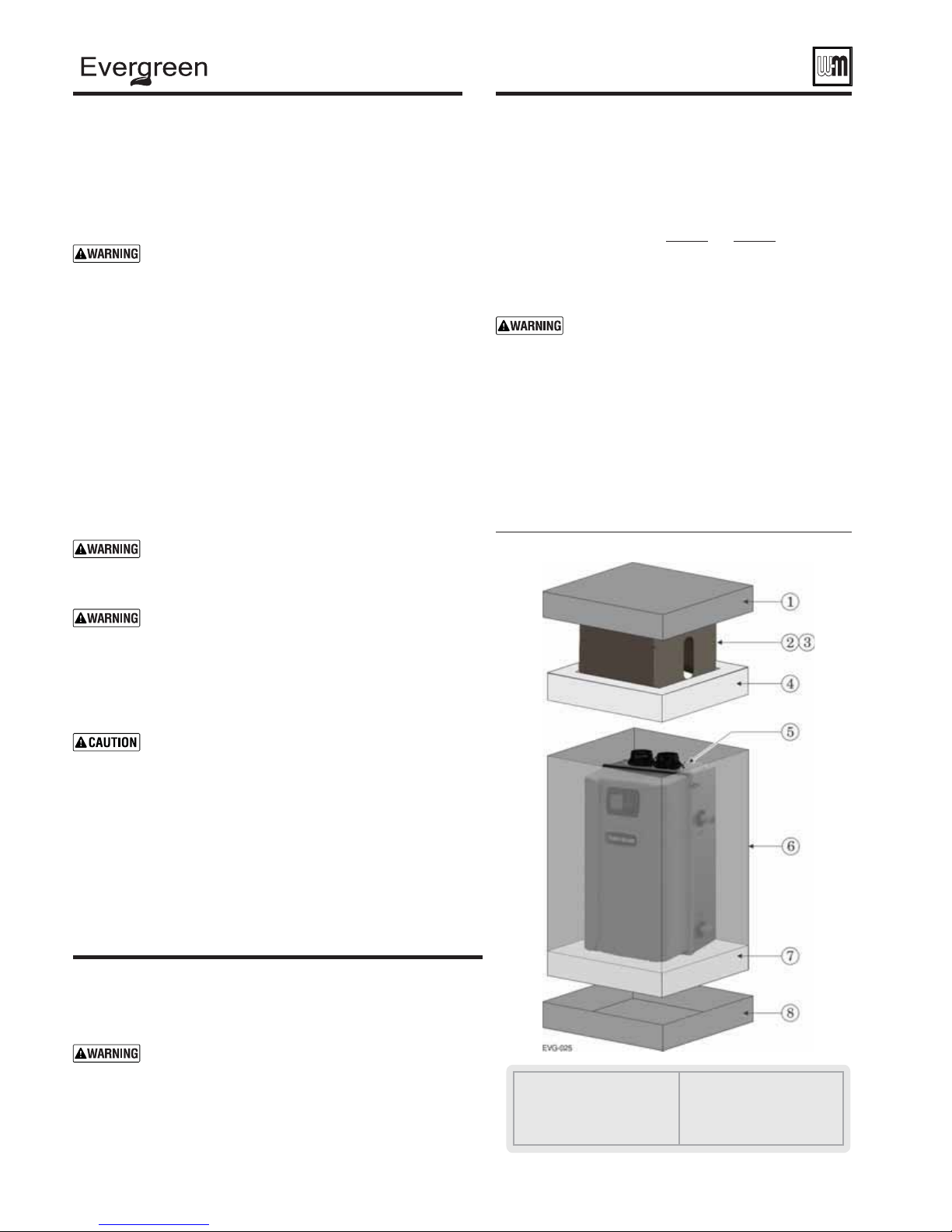
Remove boiler from crate
Do not drop boiler or bump jacket on fl oor or pallet.
1. The Evergreen
after removing the shipping container.
2. Remove items 1, 2, 3 and 6 in Figure 3 . Remove trim kit and parts
from item 2.
3.
Leave the boiler resting on the styrofoam protective base
(item 6) and bottom cardboard cap (item 7), until ready to place
on the wall. If removing the boiler from the shipping base, rest the
boiler on its back, NOT on its bottom.
®
: 18 inches wide x 18 inches deep
The boiler is heavy. Use caution not to drop the boiler
or cause bodily injury while lifting and handling. Verify
that the boiler is securely attached to prevent possibility
of boiler falling after installation.
After the boiler is removed from the shipping carton,
DO NOT allow the boiler to sit on its bottom. This would
cause pressure on protruding plastic, resulting in interior
damage. Either lay the boiler on its back or leave on the
styrofoam protective shipping base.
Damage to boiler can result.
Cold weather handling — If boiler has been stored in a
very cold location (below 0°F) before installation, handle
with care until the plastic components come to room
temperature.
®
boiler is generally easier to handle and maneuver
Wall-mounting the boiler
(continued)
The operating weights for Evergreen® boilers are:
EVG 70 112 125
EVG 110 107 120
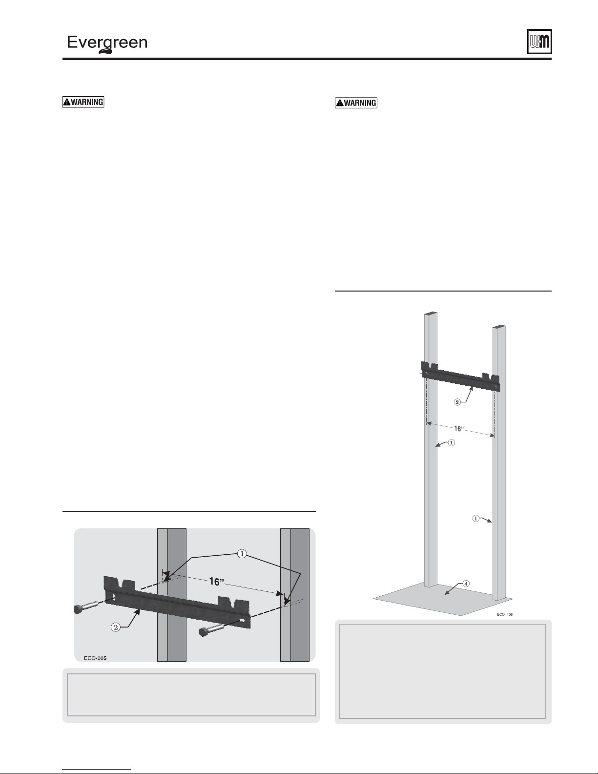
1. Stud spacing: Bracket holes are spaced for studs on
16-inch centers. For other stud spacing, provide secure,
solid mounting surface on which to attach the boiler
wall-mounting bracket. The mounting surface must not
extend above the top of the boiler jacket.
2. Wood stud wall: Install bracket with lag screws (3/8" x
3") included in kit, only into the studs.
3. Metal stud wall: Secure bracket and spacer board to studs
with 3/16-inch toggle bolts and 3/16-inch fl at washers
(not included with kit).
Figure 3 Boiler shipping container
EVG 155 129 143
Failure to comply with above and the procedure
given below could result in severe personal
injury, death or substantial property damage.
Without
Stand
lbs.
With
Stand
lbs.
Wall-mounting the boiler
Wall-mounting requirements
DO NOT attempt to attach the wall mount bracket using
anchors or any means other than directly securing to the
wall studs (or equivalent wood structure if studs are not
on 16-inch centers).
The wall must be vertically plumbed and capable of
carrying the weight of the boiler and any attached
piping components.
10
1 Cardboard cap, top
2 Floor stand assembly
3 Trim box (
4 Styrofoam protective cap
nestled inside Floor
stand assembly)
5 Boiler
6 Cardboard sleeve
7 Styrofoam protective base
8 Cardboard cap, bottom
Part number 550-100-191/0917
®
gas-fired water boiler — 70/110/155 Boiler Manual
Wall-mounting the boiler (continued)
Verify that the studs are suitable for carrying a wall-
mounted load. Some metal studs are not designed for
this purpose.
4. If the mounting wall has exposed studs, installer must provide a
backer board to mount boiler. Boiler cannot be leveled without a
backing surface.
5. Mount the boiler on the wall following these instructions. The
boiler mounting studs must engage with the wall-mount bracket.
Make sure the bracket is not just resting on the edge of the mounting
stud or washer. Perform all procedures given in the Boiler Manual
on previous pages before mounting the boiler.
Install the wall-mount bracket (by installer)
1. See Figure 4 .
2. Locate the studs — must be on 16-inch centers. See previous
page instructions if studs are not on 16-inch centers.
3. Place the wall-mount bracket (Figure 4, item 2) on the wall, using
a level to align correctly.
4. Place the wall-mount bracket so the mounting slots are centered
over the studs.
5. Level the bracket and trace the outline of the screw slots with a
pencil.
6. Remove the mounting bracket and drill holes 1/4" diameter by 3
inches deep, centered on the screw slot outlines. (For metal stud
walls, using 3/16" toggle bolts, drill required clearance holes.)
7. Position the wall-mount bracket on the wall. Insert and loosely
tighten the two lag screws (or toggle bolts for metal studs).
8. Level the wall-mounting bracket. Then tighten lag screws securely.
For drywall or plaster lathe installations, avoid tightening so
much that the bracket digs into the wall surface.
The boiler is heavy, and requires two
people to lift and place. Wear non-slip
leather gloves to prevent possibility of cuts
from sheet metal edges.
The jacket door can be left in place when
handling the boiler, but the boiler must
ONLY be lifted by the bottom and rear of
the sheet metal housing — NOT by any pipe
or plastic part.
3. Obtain assistance to lift the boiler into
position.
4. Lift the boiler high enough that its mounting studs
( Figure 6, page 12 , item 3) will be above the wallmount bracket (item 2).
5. Let the rear of the boiler slide against the lag screw
heads as you lower the boiler into place. The V-groove
will help guide the studs into the slot.
Figure 5 Place boiler on wall-mount bracket
Place boiler on bracket
1. See Figure 5 . The wall-mount bracket must be installed before
mounting the boiler.
2. Measure 22 1/2 inches below the bottom edge of the wall-mount
bracket (item 2). Strike a line or place a piece of masking tape
with its top edge even with the 22 1/2-inch mark. (This line, or
tape, will indicate whether the boiler has been properly seated
onto the wall-mount bracket.)
Figure 4 Wall-mount bracket and studs
1 Studs — Pre-drill through the wall into the studs ¼ inch diameter x 3 inches deep for
3/8-inch lag screws— Studs must be on 16-inch centers. If studs are any other spacing,
provide a secure, solid mounting surface on which to attach the boiler wall-mounting bracket.
2 Wall-mount bracket
1 Studs — Pre-drill through the wall into the studs ¼ inch diameter x 3
inches deep — Studs must be on 16-inch centers. If studs are any other
spacing, provide a secure, solid mounting surface on which to attach
the boiler wall-mounting bracket.
2 Wall-mount bracket — secure wall mount bracket to wall as instructed
on previous page.
3 Boiler mounting studs (Figure 6 back of boiler) — The V-groove on the
wall-mount bracket will help guide the studs into the slots. The studs
are attached to the back of the boiler.
4 Floor surface
Part number 550-100-191/0917
11
(continued)
ge
®
gas-fired water boiler — 70/110/155 Boiler Manual
Floor Stand AssemblyWall-mounting the boiler
Floor Standing
Figure 6 Boiler mounting studs
3
6. When the brackets are engaged correctly, the bottom of
the boiler enclosure will be at or near the pencil line, or
tape, you applied in step 2.
7. Adjust the studs properly until engaged with the bracket
and the boiler slips into the correct position.
When mounting the boiler, use the method
described on step 2, page 11 to ensure the
mounting studs are properly engaged. If not,
the boiler could fall. Failure to comply could
result in severe personal injury, death or
substantial property damage.
8. Ensure boiler is level front-to-back.
Ensure boiler is NOT pitched upward
with the front of the boiler higher than
the back of the boiler. This can prevent
condensate from draining properly. Failure
to comply could result in severe personal
re
al
injury, death or substantial property damage.
The boiler is heavy, and requires two people to
lift and place upright. Use caution not to drop
the boiler or cause bodily injury while lifting
and handling. Wear non-slip gloves to prevent
possibility of cuts from sheet metal edges.
After the boiler is removed from the shipping
carton, DO NOT allow the boiler to sit on its
bottom, before stand is installed. Doing so may
result in damage to the condensate dish.
1. Carefully remove boiler from styrofoam protective base and set
on back. Remove door from front of boiler by loosening screw
on top of boiler and unfastening latches on side of cabinet.
2. Remove four (4) 5/16” studs from fl oor stand hardware trim
bag. Install studs by hand in rivet nuts on bottom of Evergreen
boiler. See Figure 7 .
3. Remove front access panel from stand assembly using 5/16”
driver.
4. Align holes in top of stand with studs on bottom of boiler.
Slide stand over studs. Remove 5/16” nuts from trim bag.
Install nuts on studs using ½” socket or wrench. Make sure
to align sides of stand with cabinet before tightening down
nuts. Do not overtighten.
5. Install the condensate trap assembly following instructions
on page 52
6. After confi rming nuts are tightened, obtain assistance and lift
the boiler into upright position.
7. Set boiler in place and level by adjusting leveling legs with
fl at head screwdriver.
Figure 7 Floor stand assembly (front access panel
removed)
.
®
12
(9*
Part number 550-100-191/0917
®
gas-fired water boiler — 70/110/155 Boiler Manual
Boiler hydrostatic test
DO NOT install a relief valve with a pressure
higher than 30 PSIG
allowable relief valve setting for the boiler. Failure
to comply could prevent the relief valve from
operating as needed, resulting in possibility of
severe personal injury, death or substantial property
damage.
Use two wrenches when tightening any pipe
connection to the boiler
boiler pipes from turning could damage pipes or
heat exchanger, resulting in possible severe personal
injury, death or substantial property damage.
. This is the maximum
. Failure to prevent the
Hydrostatic pressure test
Pressure test the boiler before permanently attaching water or
gas piping or electrical supply.
Install pipe fi ttings for relief valve and
P/T gauge
1. Install the reducer bushings (155 only), reducing tees, and
close nipples, shipped loose with the boiler, located and
oriented as shown in Figure 8, page 14 .
Boilers installed in locations with less than the
RECOMMENDED service clearances will need to
adjust piping layout to meet space requirements.
2. Apply pipe dope to all fi ttings sparingly.
DO NOT install the relief valve until after
the hydrostatic test. Temporarily install a ¾"
pipe plug in the relief valve location as directed in
these instructions. The plug must be removed after
the test.
TEMPORARILY insert a ¾" NPT pipe plug in the relief valve
2.
tapping. After the hydrostatic test, this plug must be removed
and the relief valve must be installed.
Fill and pressure test
1. See Figure 9, page 14 for use with the following instructions.
2. CLOSE the boiler drain valve (item 11). Connect a hose to
fresh water supply and to the drain valve.
3. Place a bucket under the ends of the isolation valves (item 9
and 10) to catch water drippings.
4. CLOSE isolation valve item 10, then crack open the valve
slightly. Leave isolation valve item 9 open.
5. Slowly open the boiler drain valve (item 11) and fresh water
supply to fi ll boiler with water. The boiler and piping will fi ll
quickly because of the low water content.
6. When water begins to fl ow from bottom isolation valve (item
10), close the valve.
7. Continue fi lling until water fl ows from top isolation valve (item
9), then close the valve.
8. When pressure on the pressure/temperature gauge (item 4)
reaches at least 45 PSIG, but no higher than 55 PSIG, CLOSE
the boiler drain valve (item 11).
9. Hold at test pressure for 10 minutes.
Do not leave boiler unattended. A cold water fi ll
could expand and cause excessive pressure, resulting
in severe personal injury, death or substantial
property damage.
10. Make sure constant gauge pressure has been maintained
throughout test. Check for leaks. Repair if found.
Leaks must be repaired at once. Failure to
do so can damage boiler, resulting in substantial
property damage.
Connect the relief valve ONLY on the
BOILER SUPPLY OUTLET, NOT the boiler
return. Connect the relief valve only as shown in
this manual. Ensure relief valve is located above
heat exchanger.
Failure to comply with the above could prevent
the relief valve from operating as needed, resulting
in possibility of severe personal injury, death or
substantial property damage.
3. Install the pressure/temperature gauge to the reducing tee as
shown in Figure 8, page 14 .
Install fi ttings and valves required for
hydrostatic testing
1. The following piping components (supplied by installer) are
required for the test confi guration:
a. Two shut-off valves (1" NPT on 70/110,
1¼" NPT on 155).
b. Two close nipples (1" NPT on 70/110,
1¼" NPT on 155).
c. ¾" NPT pipe plug.
Part number 550-100-191/0917
Do not use petroleum-based cleaning or sealing
compounds in boiler system. Gaskets and seals
in the system may be damaged. This can result in
substantial property damage.
Drain and remove fi ttings
1. Disconnect fi ll water hose from water source.
2. Drain boiler through drain valve
Use caution when releasing pressure from the boiler.
Rapid water fl ow could cause injury.
3. Remove hose after draining.
4. Remove nipples and valves unless they will remain for use in
the system piping.
5. Remove plug and install relief valve as specifi ed in the following
WARNING.
Remove plug from relief valve tee. Install the
relief valve in the ¾" tee. See page 43 or page 48
to install relief valve discharge piping. Failure to
install the boiler relief valve could result in severe
personal injury, death or substantial property
damage.
(item 11).
13
®
9
gas-fired water boiler — 70/110/155 Boiler Manual
Boiler hydrostatic test (continued)
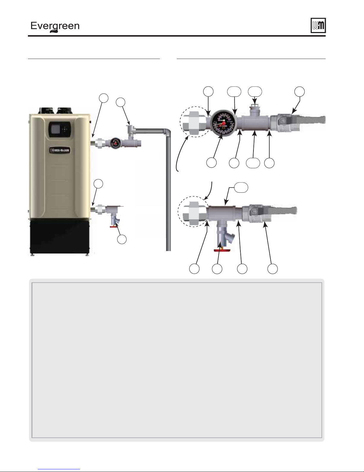
Figure 8 Install pipe fi ttings for relief valve and
pressure/temperature gauge —
NOT mount relief valve until AFTER
hydrostatic testing
(see legend below)
1
3
Piping to system
DO
2
Piping from system
Figure 9 Install piping components required for
(155 only)
Recommended but
not included
hydrostatic test (
B
see legend below)
B
C
C
11
(9*
(155 only)
1 Boiler supply (outlet) connection, (male, 1" NPT )
2 Boiler return (inlet) connection, (male, 1" NPT )
3 Boiler relief valve, shipped loose with boiler — DO NOT mount relief valve until AFTER hydrostatic testing.
3a TEMPORARILY ONLY — Insert a ¾" NPT plug in the relief valve tapping of the reducing tee. This MUST BE REMOVED after
the test and the relief valve mounted here.
4 Pressure/temperature gauge, shipped loose with boiler
5a Reducing tee, NPT, 1 " x 1 " x ¼" on 70/110, & 1 ¼" x 1 ¼" x ¼" on 155, shipped loose with boiler
5b Reducing tee, NPT, 1 " x 1 " x ¾" on 70/110, & 1 ¼" x 1 ¼" x ¾" on 155, shipped loose with boiler
6 Nipple, NPT 1" x close on 70/110, & 1 ¼" x close on 155, shipped loose with boiler
7 Bushing, NPT, 1 ¼" x 1", shipped loose with boiler (155 only)
8 Nipple, NPT 1" x close on 70/110, & 1 ¼" x close on 155, by installer
9 Isolation valve on supply connection, by installer (1" NPT on 70/110, 1¼" NPT on 155)
(9*D
10 Isolation valve on return connection, by installer (1" NPT on 70/110, 1¼" NPT on 155)
11 ¾" NPT boiler drain valve, shipped loose with boiler — after hydrostatic testing, move drain valve to lowest point on the return piping if not
already there.
14
Part number 550-100-191/0917
®
gas-fired water boiler — 70/110/155 Boiler Manual
Converting boiler to propane — EVG 70
Prepa re boiler for propane —
EVG 70 only (if required)
Propane operation
ALL Evergreen
for propane operation
Converting an existing natural gas-fi red
boiler for propane
installed, you must turn off gas supply, turn off
power and allow boiler to cool before proceeding.
You must also completely test the boiler after
conversion to verify performance and start up
the boiler following instructions beginning on
page 91 of this manual.
Failure to comply could result in severe personal
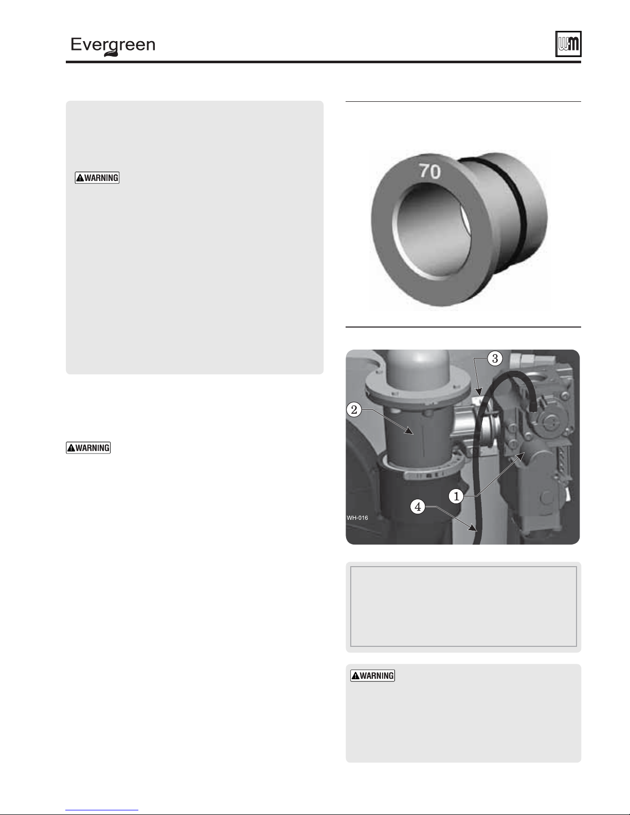
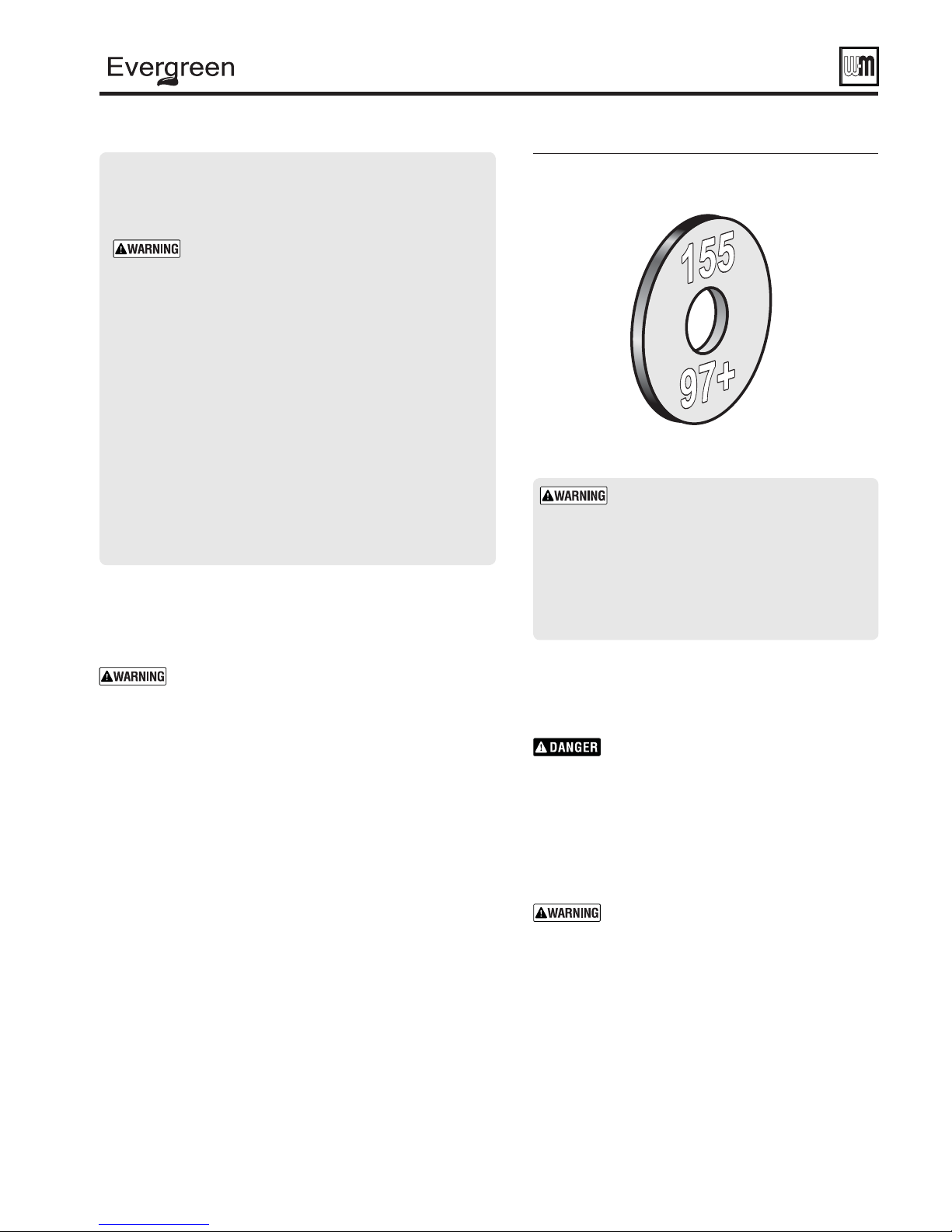
Verify 70 propane gas orifice size —
See Figure 10 . Verify when installing that the
orifi ce size marking is correct. Orifi ces will be
stamped as in illustration or with “3.75” for
model 70.
injury, death or substantial property damage.
®
boilers must be converted
.
— For a boiler already
Figure 10 Propane gas orifi ce identifi cation
EVG 70 (may be stamped 3.75)
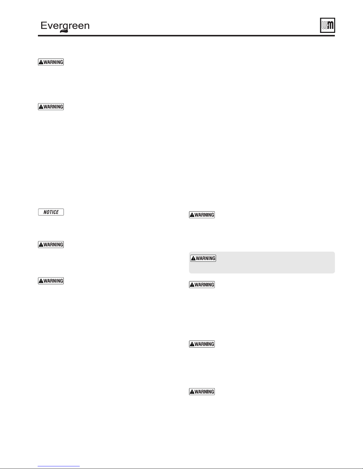
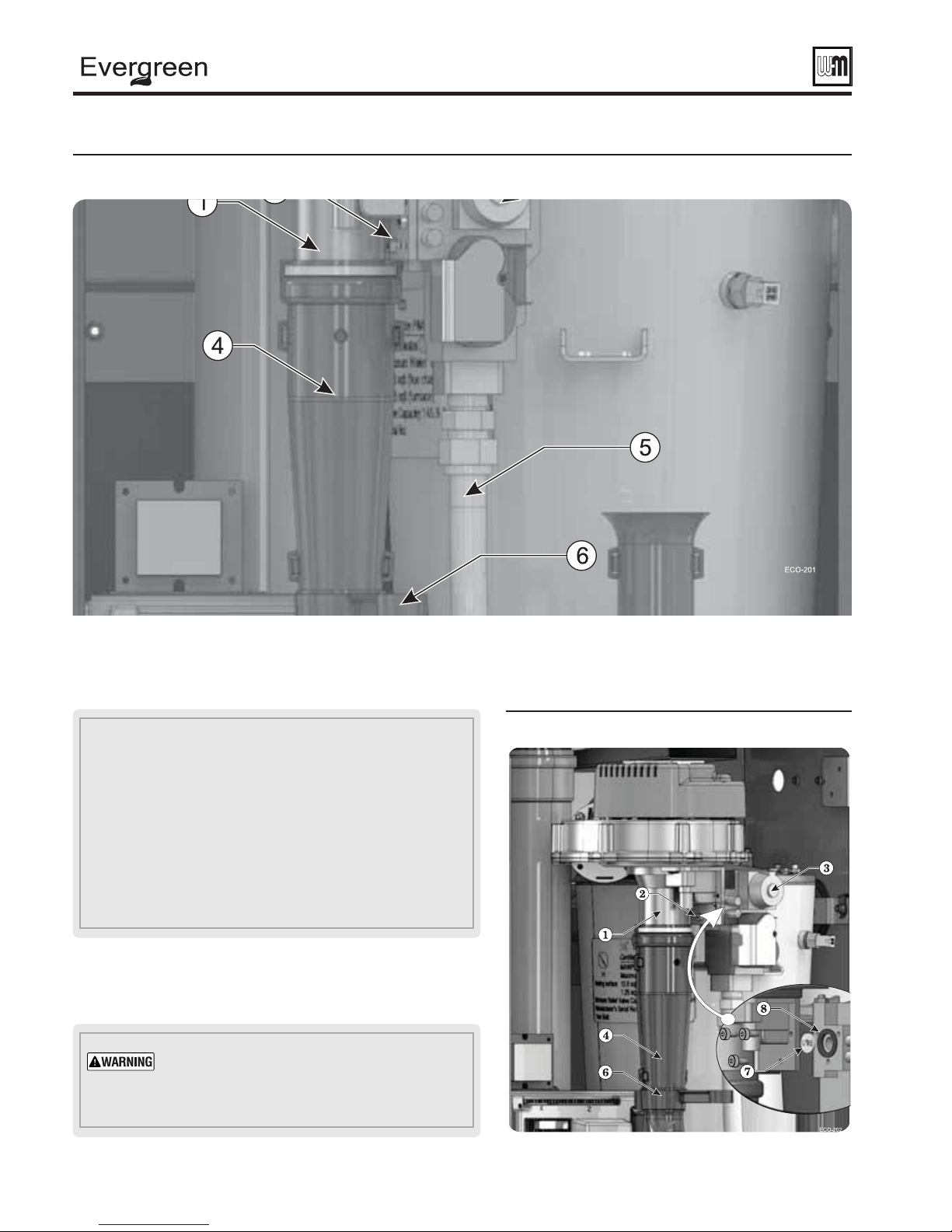
Figure 11 Gas valve and venturi
Installing propane orifi ce —
EVG 70 only
If boiler is already installed — You must turn off
electrical supply to the boiler and close the external
manual gas shut-off valve to isolate the boiler during
conversion. Allow the boiler to cool if it has been
operating.
Following conversion of an installed boiler, follow
all instructions in this manual to start up the boiler
and verify operation of the boiler and all system
components.
1. Locate the propane orifi ce from the propane conversion kit bag.
2. Verify that the stamping on the orifi ce is correct for the model
size (see Figure 10 ).
3. If the jacket door is not already removed, remove it.
4. Locate the gas valve and venturi (see Figure 11 ).
5. Pull the gas valve retention ring (item 3, Figure 11 ) off of the
gas valve/venturi joint.
6. Carefully pull the gas valve to the right until it is free of the
venturi. Leave the pressure reference hose (item 4, Figure 11 )
connected at both ends.
1 Gas valve
2 Venturi
3 Gas valve retention ring
4 Pressure reference hose — LEAVE CONNECTED AT BOTH
ENDS
Support the gas valve after disconnecting
it. DO NOT allow it to hang from the gas
valve fl ex line. When re-attaching the gas
valve, ensure the gas valve-to-venturi O-ring
(item 5, Figure 12, page 16 ) is in place and
in good condition. Inspect the gas valve fl ex
line to ensure it is undamaged and in good
condition.
Part number 550-100-191/0917
15
®
gas-fired water boiler — 70/110/155 Boiler Manual
Converting boiler to propane — EVG 70
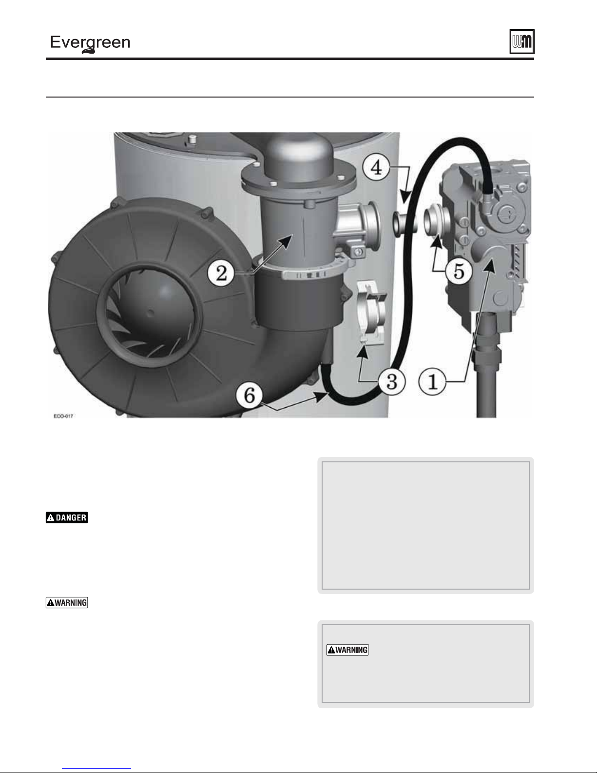
Figure 12 Installing the propane gas orifi ce (some details omitted for clarity)
(continued)
7. See Figure 12 . Insert the propane gas orifi ce (item 4) into the gas
valve outlet as shown.
8. Press the orifi ce into the gas valve outlet until the bushing fl ange
butts against the gas valve outlet.
Inspect the O-rings on the propane gas orifi ce an on the
gas valve outlet (item 5, Figure 12 ). The O-rings must
be in good condition and must be installed. Failure to
comply will cause a gas leak, resulting in severe personal
injury or death.
9. Reposition gas valve into the venturi and reinstall the gas valve
retention ring (item 3, Figure 12 ).
DO NOT ATTEMPT TO MEASURE VALVE OUTLET
PRESSURE.
fl uid contamination. Failure to comply could result in
severe personal injury, death or substantial property
damage.
10. After installation is complete, attach the propane conversion label
(in conversion kit bag) next to the boiler rating plate.
11. Perform complete start-up sequence (beginning on page 91 ),
including check for gas leaks and checking for proper operation.
12. Reinstall jacket door.
16
The valve could be damaged by manometer
LEGEND for Figure 12
1 Gas valve
2 Venturi
3 Gas valve retention ring
4 Propane orifi ce with o-ring
5 Gas valve o-ring
6 Pressure reference hose — LEAVE CONNECTED AT BOTH
ENDS
The jacket door must be in place
during operation.
the boiler with the jacket door removed
except for inspection and testing as
directed in this manual.
DO NOT operate
Part number 550-100-191/0917
®
gas-fired water boiler — 70/110/155 Boiler Manual
Converting boiler to propane — EVG 110
Prepa re boiler for propane —
EVG 110 only (if required)
Propane operation
ALL Evergreen
for propane operation
Converting an existing natural gas-fi red
boiler for propane
installed, you must turn off gas supply, turn
off power and allow boiler to cool before
proceeding. You must also completely test the
boiler after conversion to verify performance
and start up the boiler following instructions
beginning on page 91 of this manual.
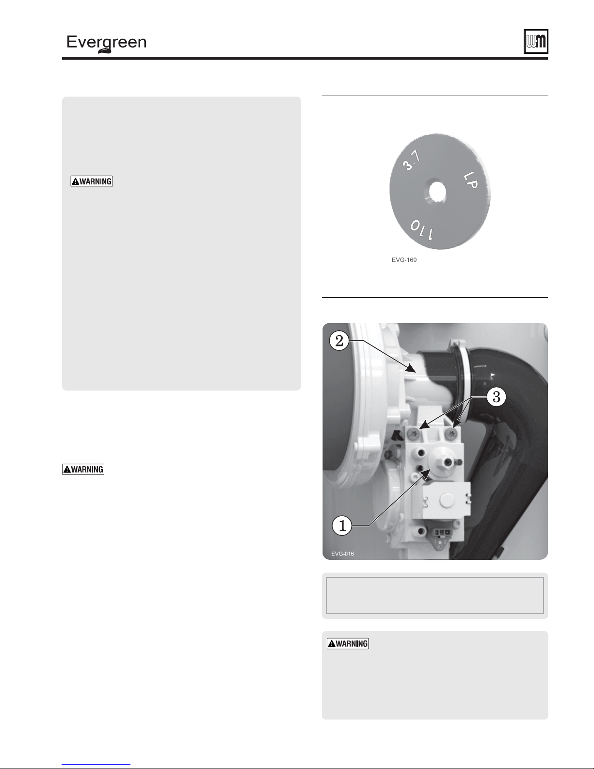
Verify 110 propane gas orifice size —
See Figure 13 . Verify when installing that the
orifi ce size marking is correct. Orifi ces will be
stamped as in illustration or “3.7” for model
110.
®
boilers must be converted
.
— For a boiler already
Figure 13 Propane gas orifi ce identifi cation
EVG 110 (may be stamped 3.7
Figure 14 EVG 110 Gas valve and venturi
only
)
Failure to comply could result in severe personal
injury, death or substantial property damage.
Installing propane orifi ce —
EVG 110 only
If the boiler is already installed — You must turn
off electrical supply to the boiler and close the external
manual gas shut-off valve to isolate the boiler during
conversion. Allow the boiler to cool if it has been
operating.
Following conversion of an installed boiler, follow
all instructions in this manual to start up the boiler
and verify operation of the boiler and all system
components.
1. Locate the propane orifi ce from the propane conversion kit bag.
2. Verify that the stamping on the orifi ce is correct for the model
size (see Figure 13 ).
3. If the jacket door is not already removed, remove it.
4. Locate the gas valve and venturi (see Figure 14 ).
5. Release the gas line from the silencer bracket clip (item 5, page
18) and rotate it out of the way.
6. Use a T25-mm torx bit to remove the two (2) bolts (item 3)
that secure the gas valve to the venturi.
1 Gas valve
2 Venturi
3 Gas valve screws to venturi
Support the gas valve after disconnecting
it. DO NOT allow it to hang from the gas
valve fl ex line. When re-attaching the gas
valve, ensure the gas valve propane orifi ce
is properly seated in rubber boot (item 6,
Figure 15, page 18 ) and is in place and in good
condition. Inspect the gas valve fl ex line to
ensure it is undamaged and in good condition.
Part number 550-100-191/0917
17
®
gas-fired water boiler — 70/110/155 Boiler Manual
Converting boiler to propane — EVG 110
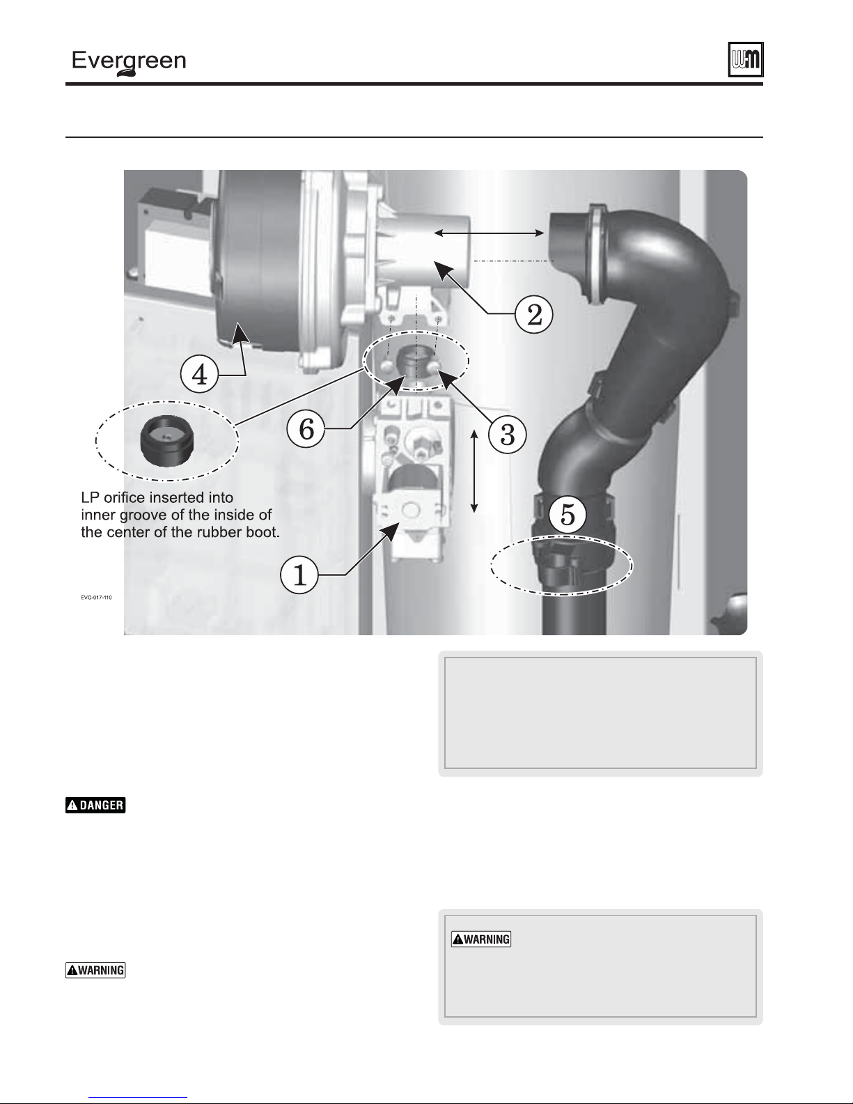
Figure 15 EVG-110 -Installing the propane gas orifi ce (some details omitted for clarity)
(continued)
7. See Figure 15 , Carefully pull the gas valve down until it is free
of the venturi. Securely support the gas valve — DO NOT
leave it dangling.
8. Remove the rubber boot from the gas valve or venturi.
9. Insert the propane gas orifi ce into the rubber boot. Orifi ce
must be seated into the inner groove inside the center of the
rubber boot.
10. Install the rubber boot (item 6) guaranteeing that it is fi rmly
seated on the gas valve opening.
When re-attaching the gas valve, ensure the gas
valve rubber boot (item 6, Figure 15 ) is in place
and in good condition.
Failure to comply will cause a gas leak, resulting
in severe personal injury or death.
11. Reposition gas valve onto the venturi and reinstall the gas
valve retention bolts (item 3). Make sure the rubber boot is
fully seated on both the gas valve and venturi.
12. Swing the silencer bracket clip (item 5) back into position
and snap on to the gas line.
DO NOT ATTEMPT TO MEASURE VALVE
OUTLET PRESSURE.
damaged by manometer fluid contamination.
Failure to comply could result in severe personal
injury, death or substantial property damage.
18
The valve could be
LEGEND for Figure 15
1 Gas valve
2 Venturi
3 Bolts (2) for attaching gas valve to venturi
4 Blower
5 Air silencer bracket clip
6 Propane orifi ce with boot
13. After installation is complete, attach the propane conversion
label (in conversion kit bag) next to the boiler rating plate.
14. Perform complete start-up sequence (beginning on
page 91 ), including check for gas leaks and checking for
proper operation.
15. Reinstall jacket door.
The jacket door must be in place during
operation.
with the jacket door removed except for
inspection and testing as directed in this
manual.
DO NOT operate the boiler
Part number 550-100-191/0917
®
gas-fired water boiler — 70/110/155 Boiler Manual
Converting boiler to propane — EVG 155
Prepa re boiler for propane —
EVG 155 only (if required)
Propane operation
ALL Evergreen
for propane operation
Failure to comply could result in severe personal
Converting an existing natural gas-fired
boiler for propane
installed, you must turn off gas supply, turn off
power and allow boiler to cool before proceeding.
You must also completely test the boiler after
conversion to verify performance and start up the
boiler following instructions beginning on page 91
of this manual.
Verify propane gas orifice size — See
Figure 16 . Verify when installing that the orifi ce
size marking is correct. Orifi ce will be stamped as
in illustration.
injury, death or substantial property damage.
®
boilers must be converted
.
— For a boiler already
Installing propane orifi ce —
EVG 155 only
If boiler is already installed — You must turn off
electrical supply to the boiler and close the external
manual gas shut-off valve to isolate the boiler during
conversion. Allow the boiler to cool if it has been
operating.
Following conversion of an installed boiler, follow
all instructions in this manual to start up the boiler
and verify operation of the boiler and all system
components.
1. Locate the propane orifi ce from the propane conversion kit bag.
2. Verify that the stamping on the orifi ce is correct for the model
size (see Figure 16 ).
3. If the jacket door is not already removed, remove it.
4. See Figure 17, page 20 and Figure 18, page 20 for the following.
5. Locate the gas valve and venturi (items 1 and 3).
6. Release the gas line to silencer bracket (item 6) from the gas line
and rotate it forward out of the way.
7. Use a 5mm hex wrench to remove the three (3) Allen screws
(item 2) that secure the gas valve to the venturi.
8. See Figure 18, page 20 . Carefully pull the gas valve to the right
until it is free of the venturi. Securely support the gas valve —
DO NOT leave it dangling.
Figure 16 Propane gas orifi ce identifi cation
EVG 155
Support the gas valve after
disconnecting from the venturi. DO
NOT allow it to hang from the gas
valve fl ex line.
valve, ensure the gas valve grommet (item
8, Figure 18, page 20 ) is in place and in
good condition. Inspect the gas valve fl ex
line to ensure it is undamaged and in good
condition.
9. Insert the propane gas orifi ce (item 7) into the gas valve
opening as shown in Figure 18, page 20 .
10. Make sure that the rubber grommet (item 8) is fi rmly
seated in the gas valve opening.
When re-attaching the gas valve, ensure the
gas valve grommet (item 8, Figure 18, page 20 )
is in place and in good condition. Failure to
comply will cause a gas leak, resulting in severe
personal injury or death.
11. Reposition gas valve onto the venturi and reinstall the
gas valve retention screws (item 2).
12. Swing the gas line to silencer bracket (item 6) back into
position and snap onto the gas line.
DO NOT ATTEMPT TO MEASURE VALVE
OUTLET PRESSURE.
damaged by manometer fl uid contamination.
Failure to comply could result in severe
personal injury, death or substantial property
damage.
13. After installation is complete, attach the propane
conversion label (in conversion kit bag) next to the
boiler rating plate.
14. Perform complete start-up sequence (beginning on
page 91 ), including check for gas leaks and checking
for proper operation.
15. Reinstall jacket door.
When re-attaching the gas
The valve could be
Part number 550-100-191/0917
19
®
gas-fired water boiler — 70/110/155 Boiler Manual
Converting boiler to propane — EVG 155 (continued)
Figure 17 Installing the propane gas orifi ce (some details omitted for clarity)
LEGEND for Figure 17 and Figure 18
1 Venturi (leave venturi attached to blower)
2 (3) hex-head screws, 5 mm hex (remove and retain)
3 Gas valve
4 Air silencer (leave connected to venturi)
5 Flexible gas line
6 Gas line to silencer bracket (rotate forward before disconnecting gas valve
from venturi
7 Propane orifi ce (in propane conversion kit envelope)
8 Rubber grommet (must be installed in valve for all applications) — make
sure grommet is properly seated in valve before inserting the propane
orifi ce
The jacket door must be in place during
operation.
DO NOT operate the boiler with the
jacket door removed except for inspection and
testing as directed in this manual.
Figure 18 Gas valve and venturi
20
Part number 550-100-191/0917
®
gas-fired water boiler — 70/110/155 Boiler Manual
Gas piping — sizing gas lines
Boiler gas connection is ½" NPT. Size gas lines large
enough to provide gas to all connected appliances.
Natural Gas:
Pipe sizing for natural gas
1. Size gas piping from meter outlet to entrance of boiler in
accordance with Figure 19 and Figure 20 .
2. Use total input of all connected appliances. Divide total input
in Btuh by 1,000 to obtain cubic feet per hour of natural gas.
a. Pipe lengths in Figure 19 are equivalent length of straight
pipe. Convert pipe fi ttings to equivalent lengths using data
from Figure 20 .
b. Figure 19 is only for natural gas with specifi c gravity 0.60,
with a pressure drop through the gas piping as listed in the
table.
c. For additional gas pipe sizing information, refer to ANSI
Z223.1 NFPA 54 - latest edition (or Natural Gas and Propane
Installation CAN/CSA B149.1 or B149.2 for Canadian
installations).
Natural gas s upply pressure
1. Pressure required at gas valve inlet pressure port:
a. Maximum: 13" (330 mm) w.c. with no fl ow (lockup).
b. Minimum gas pressure, with gas fl owing (verify during
boiler startup, while boiler is at high fi re):
EVG 70: 3½" (89 mm) w.c.
EVG 110: 3½" (89 mm) w.c.
EVG 155: 3½" (89 mm) w.c.
c. Nominal gas pressure: 7.0" (178 mm) w.c.
2. Install 100% lockup gas pressure regulator in supply line if inlet
pressure can exceed 13" w.c. at any time. Adjust lockup regulator
for 13" w.c. maximum.
Propane Gas:
You must follow the instructions, beginning on
page 15 , to operate the boiler on propane. Failure to
comply could result in severe personal injury, death or
substantial property damage.
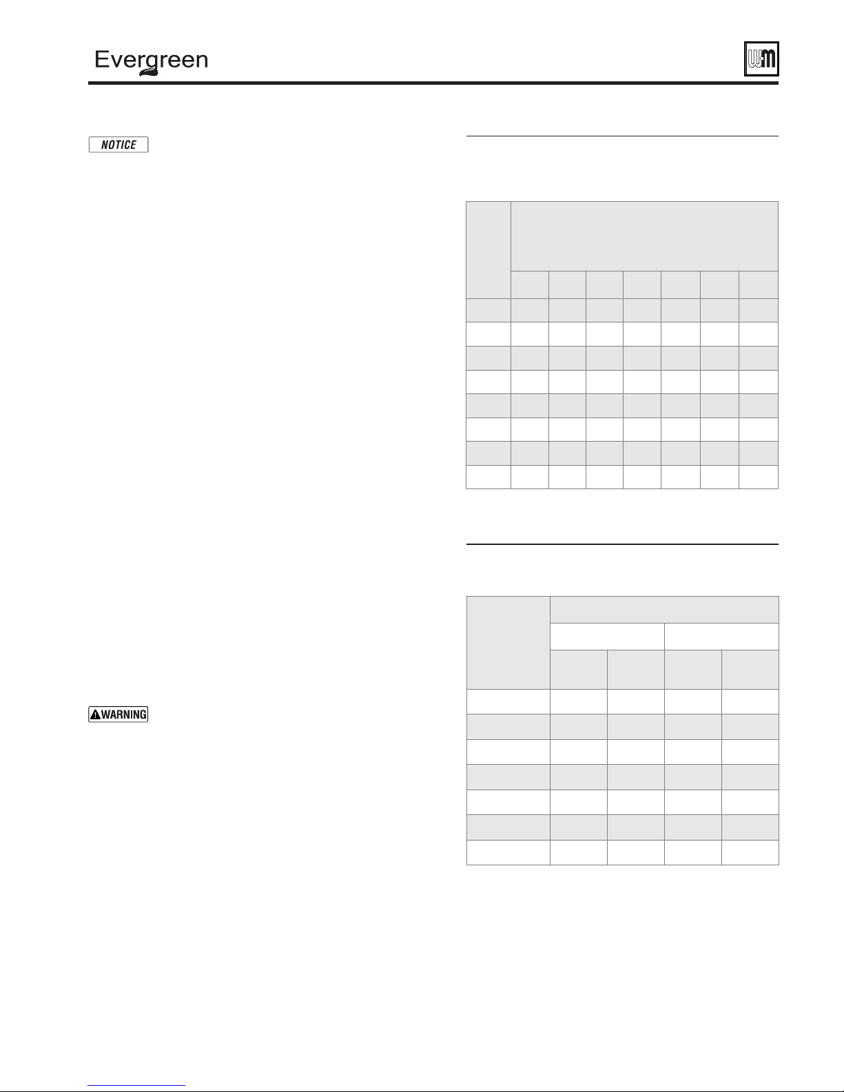
Figure 19 Pipe capacity for 0.60 specifi c gravity
natural gas; pipe length is in equivalent
feet.
Gas
Cubic feet per hour, natural gas, 0.60 specifi c gravity
pipe
total
length,
feet
10 132 278 520 1050 1600 3050 4800
20 92 190 350 730 1100 2100 3300
30 73 152 285 590 890 1650 2700
40 NA 130 245 500 760 1450 2300
50 NA 115 215 440 670 1270 2000
75 NA 105 175 360 545 1020 1650
100 NA 96 150 305 460 870 1400
150 NA 90 120 250 380 710 1130
Gas pressure 13" (330 mm) w.c. or less
Pressure drop 0.3 inches (7.6 mm) w.c
½" ¾" 1" 1¼" 1½" 2" 2½"
Capacity
.
Figure 20 Equivalent lengths of straight pipe for
typical gas line fi ttings.
Equivalent length, feet
Pipe size
inches
½
¾
1
90° Elbow Tee
short
radius
3.6 2.2 1.7 4.2
4.4 2.3 2.4 5.3
5.2 2.7 3.2 6.6
long
radius
line
fl ow
branch
fl ow
Pipe sizing for propane gas
1. Contact gas supplier to size pipes, tanks and 100% lockup gas
pressure regulator.
Propane supply pressure
1. Adjust propane supply regulator provided by gas supplier for
13" (330 mm) w.c. maximum pressure.
2. Pressure required at gas valve inlet pressure port:
a. Maximum: 13" (330 mm) w.c. with no fl ow (lockup).
b. Minimum gas pressure, with gas fl owing (verify during
boiler startup, while boiler is at high fi re):
EVG 70: 3½" (89 mm) w.c.
EVG 110: 3½" (89 mm) w.c.
EVG 155: 3½" (89 mm) w.c.
c. Nominal gas pressure: 11.0" (279 mm) w.c.
Part number 550-100-191/0917
1¼
1½
2
2½
6.6 3.2 4.6 8.7
7.4 3.4 5.6 9.9
8.5 3.6 7.7 12.0
9.3 4.0 9.3 13.0
21
®
gas-fired water boiler — 70/110/155 Boiler Manual
Venting/air piping — general
Any improper operation of the common venting system should be
corrected so the installation conforms with the National Fuel Gas
Code, ANSI Z223.1/NFPA 54- latest edition, and/or the Natural Gas
and Propane Installation Code, CAN/CSA B149.1. When resizing any
portion of the common venting system, the common venting system
should be resized to approach the minimum size as determined using the
appropriate tables in Chapter 13 of the National Fuel Gas Code, ANSI
Z223.1/NFPA 54 - latest edition, and/or the Natural Gas and Propane
Installation Code, CAN/CSA B149.1.
Do not install the Evergreen® boiler into a common vent
with any other appliance. This will cause fl ue gas spillage or
appliance malfunction, resulting in possible severe personal
injury, death or substantial property damage.
Existing common vent systems may be too large for the
appliances remaining connected after the existing boiler is
removed.
Failure to follow all instructions can result in fl ue gas spillage
and carbon monoxide emissions, causing severe personal
injury or death.
When removing a boiler from an existing
common vent system
The Evergreen® boiler cannot be common vented with any other
appliance
. When an existing boiler is replaced with an Evergreen® boiler,
the Evergreen® boiler CANNOT use the existing common vent. The boiler
requires its own vent and air piping, as specifi ed in this manual. This may
cause a problem for the appliances that remain on the old common vent,
because the vent may be too large. The following test is intended to check
for proper operation of the appliances remaining on the old common vent
system.
Vent system verifi cation
Perform the test sequence below for each appliance remaining on the
original common vent system. Operate each appliance individually, with
other appliances turned off. This procedure will test whether the common
vent system can properly vent each appliance.
Existing vent test procedure
(The following is intended to test whether the appliances remaining
on an existing vent system will operate satisfactorily.)
1. Seal any unused openings in the common venting system.
2. Visually inspect the venting system for proper size and horizontal pitch
and determine there is no blockage or restriction, leakage, corrosion or
other defi ciencies which could cause an unsafe condition.
3. Test vent system — Insofar as is practical, close all building doors and
windows and all doors between the space in which the appliances
remaining connected to the common venting system are located and
other spaces of the building. Turn on clothes dryers and any appliance
not connected to the common venting system. Turn on any exhaust
fans, such as range hoods and bathroom exhausts, so they will operate
at maximum speed. Do not operate a summer exhaust fan. Close
fi replace dampers.
4. Place in operation the appliance being inspected. Follow the lighting
instructions. Adjust thermostat so appliance will operate continuously.
5. Test for spillage at draft hood relief opening after 5 minutes of main
burner operation. Use the fl ame of a match or candle, or smoke from
a cigarette, cigar, or pipe.
6. After it has been determined that each appliance remaining connected
to the common venting system properly vents when tested as outlined
herein, return doors, windows, exhaust fans, fi replace dampers, and
any other gas-burning appliance to their previous conditions of use.
You must pipe combustion air to the
boiler air intake
Install air inlet piping for the Evergreen
.
®
boiler as described in this manual.
The air termination fitting must
be installed with the clearances and
geometry relative to the vent outlet
depicted in this manual to ensure that
fl ue products do not enter the air intake.
Ensure that the combustion air will
not contain any of the contaminants
in Figure 16. Do not pipe combustion
air near a swimming pool, for example.
Avoid areas subject to exhaust fumes
from laundry facilities. These areas will
always contain contaminants.
Contaminated combustion air will
damage the boiler, resulting in possible
severe personal injury, death or
substantial property damage.
Figure 21 Corrosive contaminants and sources
Products to avoid
Spray cans containing chloro/fl uorocarbons
Permanent wave solutions
Chlorinated waxes/cleaners
Chlorine-based swimming pool chemicals
Calcium chloride used for thawing
Sodium chloride used for water softening
Refrigerant leaks
Paint or varnish removers
Hydrochloric acid/muriatic acid
Cements and glues
Antistatic fabric softeners used in clothes dryers
Chlorine-type bleaches, detergents, and cleaning
solvents found in household laundry rooms
Adhesives used to fasten building products and other
similar products
Excessive dust and dirt
Areas likely to have contaminants
Dry cleaning/laundry areas and establishments
Swimming pools
Metal fabrication plants
Beauty shops
Refrigeration repair shops
Photo processing plants
Auto body shops
Plastic manufacturing plants
Furniture refi nishing areas and establishments
New building construction
Remodeling areas
Garages with workshops
22
Part number 550-100-191/0917
®
gas-fired water boiler — 70/110/155 Boiler Manual
Venting & air — general (continued)
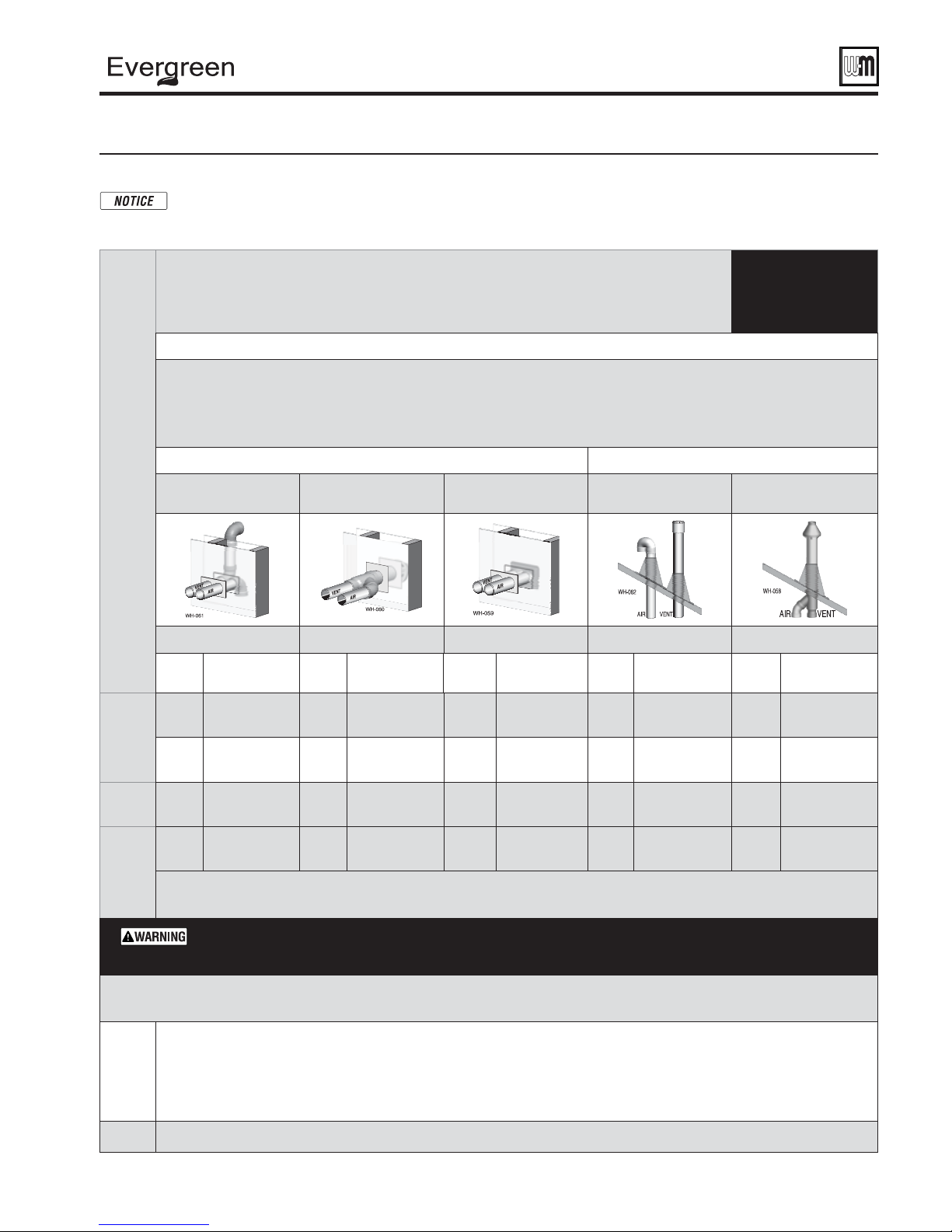
Figure 22 Evergreen
The table below lists the acceptable vent/air pipe terminations described in this manual. Follow all instructions provided to install the
vent/air system.
For these applications, use ONLY the manufacturers’ parts listed and follow all instructions provided by the pipe manufacturer.
Maximum vent and air pipe length = 100 feet for all applications
(All applications include allowance for the termination fi ttings plus one elbow in air piping and one elbow in vent piping).
See Figure23,page24 for material speci cations | See Figure110,page127 for part/kit numbers
If using 2" pipe, provide 3"x 2" tapered reducers at boiler connections and at Weil-McLain vent/air cap or at concentric terminations.
Boilers will derate as vent/air pipe length increases — see rating data on Figure123,page139 for derate amounts.
Model
®
Separate pipes
[Note 1]
Evergreen
®
venting and air piping — DIRECT VENT ONLY — OPTIONS and PIPING LIMITS
NOT SHOWN below, but also approved, are the polypropylene piping and terminations listed in Figure 23, page 24 .
USE SWEEP
(Minimum length for all applications is 2 feet)
ELBOWS
ONLY
Vent and air pipe sizes:
Maximum vent lengths apply for either 2" or 3" vent and air pipe.
SIDEWALL termination VERTICAL termination
PVC or PP Concentric
[Note 1]
3” Weil-McLain PVC
vent/air cap [Note 1]
Separate pipes
[Note 1]
PVC or PP Concentric
[Note 1]
See page 28 See page 30 See page 32 See page 32 See page 36
Size,
inches
2
70
3
110
155
Equivalent feet for elbows (USE SWEEP ELBOWS ONLY) —
• 7 feet per for each additional 90° sweep elbow or 45° elbow —
Note 1:
3
3
** Model 155 may be concentric sidewall vented using Centrotherm polypropylene pipe (Eco Systems InnoFlue® Single-wall) ONLY
if using Centrotherm stainless steel concentric termination kit, part number ICWS3513.
Material abbreviations: PP = polypropylene, SS = AL29-4C stainless steel
If using polypropylene or stainless pipe, provide adapters to for 3” boiler connections and for terminations, if required
IPEX 3” PVC concentric vent kits can be used with standard PVC pipe, fi ttings and cement (ANSI/ASTM D1785) except if ULC S636
compliance is required. For ULC S636 compliance, all pipe, fi ttings and cement must be IPEX System 636. If using IPEX kits, use only
IPEX product code 196006 for 3” venting.
Contact Weil-McLain for ordering information and availability of Weil-McLain venting kits.
Materials
Fig. 23, page 24
PVC/PVC-DWV
CPVC, PP, SS
PVC/PVC-DWV
CPVC, PP, SS
PVC/PVC-DWV
CPVC, PP, SS
PVC/PVC-DWV
CPVC, PP, SS
All elbows in vent and air piping must be sweep elbows ONLY. DO NOT use short-radius elbows. When
transitioning to 3" to 2", use tapered reducer with 3" PVC nipple (L 6"). Do not use 3" to 2" bushing.
Bushings will not seal in boiler adapters.
Size,
inches
2
3
3
3
Materials
Fig. 23, page 24
PVC/PVC-DWV
CPVC, PP, SS
PVC/PVC-DWV
CPVC, PP, SS
PVC Concentric
only
PVC/PVC-DWV
CPVC, SS, PP**
Size,
inches
2
3
––3
3
deduct from max. equivalent length of piping (does not apply to termination fi ttings).
If piping contains more than 1 elbow in air or vent piping, other than termination fi ttings.
Materials
Fig. 23, page 24
PVC/PVC-DWV
CPVC, PP, SS
PVC/PVC-DWV
CPVC, PP, SS
PVC/PVC-DWV
CPVC, PP, SS
Size,
inches
2
3
3
Materials
Fig. 23, page 24
PVC/PVC-DWV
CPVC, PP, SS
PVC/PVC-DWV
CPVC, PP, SS
PVC/PVC-DWV
CPVC, PP, SS
PVC/PVC-DWV
CPVC, PP, SS
Size,
inches
2
3
3
3
Materials
Fig. 23, page 24
PVC/PVC-DWV
CPVC, PP, SS
PVC/PVC-DWV
CPVC, PP, SS
PVC/PVC-DWV
CPVC, PP, SS
PVC/PVC-DWV
CPVC, SS,
Note 2: Use only Weil-McLain approved termination kits listed in Figure 110, page 127
Part number 550-100-191/0917
23
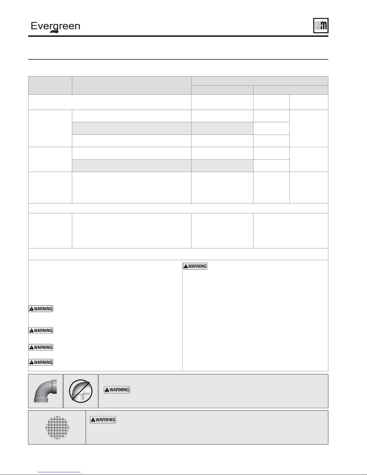
®
gas-fired water boiler — 70/110/155 Boiler Manual
Venting & air — general (continued)
Figure 23 Vent and air piping materials — Use only the materials listed below, ensuring that all materials meet
local codes (see Figure 110, page 127 for part/kit numbers)
Item Material
Plastic piping materials Vent or air piping
Vent or air pipe
&
fi ttings
PVC & ABS pipe
cement & primer
Polypropylene
vent pipe, fi ttings,
terminations and
cement
Simpson-Duravent — Obtain all materials from M&G
Simpson-Duravent
Centrotherm Eco Systems InnoFlue
Obtain all materials from Centrotherm
Note: See page 127 for correct appliance adapters to be used.
PVC-DWV schedule 40 (Note 1) ANSI/ASTM D2665 NA
CPVC schedule 40 (Note 1) ANSI/ASTM F441 ULC S636
PVC schedule 40 ANSI/ASTM D1785 ULC S636
PVC ANSI/ASTM D2564/F656 ULC S636
CPVC (Note 1) ANSI/ASTM F493 ULC S636
See manufacturer’s literature for
®
Single-wall —
detailed information
MUST USE LOCKING
COLLAR ON EVERY JOINT
Standards for installations in:
United States Canada
Vent
piping
ULC S636
(Note 2)
Air
piping
PVC, PVC-DWV,
CPVC or
polypropylene
Use only cement
and primer
suitable for piping
material used
PVC, PVC-DWV,
CPVC or
polypropylene
AL29-4C stainless steel piping materials
®
Certifi ed for Category IV and
direct vent appliance venting
®
Certifi ed for Category IV and direct
vent appliance venting
Vent pipe
AL29-4C
stainless
steel
Heat Fab, Inc. — Saf-T-Vent
Z-Flex, Inc. — Z-Vent II
Dura-Vent — FasNSeal™
Metal-Fab, Inc. — CORR/GUARD
Centrotherm Eco Systems — InnoFlue
Weil-McLain stainless steel bird screens, 2" or 3" (purchase separately) — see Figure 110, page 127 for part numbers
Note 1: Weil-McLain concentric vent kits are made from PVC pipe
and ttings.
Note 2: System 636 PVC concentric terminations utilize PVC
pipe/ ttings certi ed to ULC S636.
If ULC S636 compliance is required, use only System 636
pipe, ttings and cement.
DO NOT mix piping from di erent pipe manufacturers
unless using adapters speci cally designed for the purpose
by the manufacturer.
Every joint on polypropylene vent piping must include
ADAPTERS — Polypropylene piping — Provide adapters
ADAPTERS — AL29-4C piping — Install a PVC-to-stainless
adapter supplied by the AL29-4C stainless pipe
manufacturer at the 3" PVC boiler vent connection
and at the termination (if using Weil-McLain plate or
concentric PVC termination).
from polypropylene pipe to the 3" PVC connections at
the boiler and at terminations, if required (Weil-McLain
sidewall plate, for example).
a locking collar.
DO NOT use cellular core PVC (ASTM F891), cellular core
CPVC, or Radel® (polyphenolsulfone) in venting systems.
DO NOT cover non-metallic vent pipe and ttings with
thermal insulation.
ADAPTERS — If using 2" piping, where approved for
the application, provide adapters for the 3" PVC boiler
connections and at the terminations, if required (WeilMcLain sidewall plate, for example)
USE SWEEP ELBOWS FOR ALL VENT AND AIR PIPING — DO NOT use short
radius elbows for vent or air piping. Boiler performance could be a ected.
ALL vent and air pipes require a BIRD SCREEN at each termination. Most kits do not include
the bird screens. Purchase bird screens separately from Weil-McLain or vent kit supplier if
not included. [Note — bird screening is integral to the 3" PVC Weil-McLain sidewall vent
cap,
available for purchase from Weil-McLain
. No additional screening is required.]
24
Part number 550-100-191/0917

®
gas-fired water boiler — 70/110/155 Boiler Manual
Commonwealth of Massachusetts installations
Commonwealth of Massachusetts — When the boiler is installed within the Commonwealth of Massachusetts,
the boiler must be installed by a licensed plumber or gas fi tter. Read and comply with the instructions below.
(a) For all sidewall horizontally-vented gas-fueled equipment
installed in every dwelling, building or structure used in
whole or in part for residential purposes, including those
owned or operated by the Commonwealth and where the
side wall exhaust vent termination is less than seven (7) feet
above fi nished grade in the area of the venting, including but
not limited to decks and porches, the following requirements
shall be satisfi ed:
1.
INSTALLATION OF CARBON MONOXIDE DETECTORS.
At the time of installation of the side wall horizontal
vented gas fueled equipment, the installing plumber
or gas fitter shall observe that a hard wired carbon
monoxide detector with an alarm and battery back-up
is installed on the fl oor level where the gas equipment is
to be installed. In addition, the installing plumber or gas
fi tter shall observe that a battery operated or hard wired
carbon monoxide detector with an alarm is installed
on each additional level of the dwelling, building or
structure served by the side wall horizontal vented gas
fueled equipment. It shall be the responsibility of the
property owner to secure the services of qualifi ed licensed
professionals for the installation of hard wired carbon
monoxide detectors.
a. In the event that the side wall horizontally vented gas
fueled equipment is installed in a crawl space or an
attic, the hard wired carbon monoxide detector with
alarm and battery back-up may be installed on the
next adjacent fl oor level.
b. In the event that the requirements of this subdivision
can not be met at the time of completion of
installation, the owner shall have a period of thirty
(30) days to comply with the above requirements;
provided, however, that during said thirty (30) day
period, a battery operated carbon monoxide detector
with an alarm shall be installed.
2.
APPROVED CARBON MONOXIDE DETECTORS. Each
carbon monoxide detector as required in accordance with
the above provisions shall comply with NFPA 720 and be
ANSI/UL 2034 listed and IAS certifi ed.
3.
SIGNAGE. A metal or plastic identifi cation plate shall
be permanently mounted to the exterior of the building
at a minimum height of eight (8) feet above grade
directly in line with the exhaust vent terminal for the
horizontally vented gas fueled heating appliance or
equipment. The sign shall read, in print size no less than
one-half (1/2) inch in size, “GAS VENT DIRECTLY
BELOW. KEEP CLEAR OF ALL OBSTRUCTIONS.”
4.
INSPECTION. The state or local gas inspector of the
side wall horizontally vented gas fueled equipment shall
not approve the installation unless, upon inspection,
the inspector observes carbon monoxide detectors and
signage installed in accordance with the provisions of
248 CMR 5.08(2)(a) 1 through 4.
(b)
EXEMPTIONS: The following equipment is exempt from
248 CMR 5.08(2)(a)1 through 4:
1. The equipment listed in Chapter 10 entitled “Equipment
Not Required To Be Vented” in the most current edition
of NFPA 54 as adopted by the Board; and
2. Product Approved side wall horizontally vented gas fueled
equipment installed in a room or structure separate from
the dwelling, building or structure used in whole or in
part for residential purposes.
(c)
MANUFACTURER REQUIREMENTS — GAS EQUIPMENT
VENTING SYSTEM PROVIDED
of Product Approved side wall horizontally vented gas
equipment provides a venting system design or venting system
components with the equipment, the instructions provided
by the manufacturer for installation of the equipment and
the venting system shall include:
1. Detailed instructions for the installation of the venting
system design or the venting system components; and
2. A complete parts list for the venting system design or
venting system.
(d)
MANUFACTURER REQUIREMENTS — GAS EQUIPMENT
VENTING SYSTEM NOT PROVIDED
of a Product Approved side wall horizontally vented gas fueled
equipment does not provide the parts for venting the fl ue
gases, but identifi es “special venting systems”, the following
requirements shall be satisfi ed by the manufacturer:
1. The referenced “special venting system” instructions shall
be included with the appliance or equipment installation
instructions; and
2. The “special venting systems” shall be Product Approved
by the Board, and the instructions for that system shall
include a parts list and detailed installation instructions.
(e) A copy of all installation instructions for all Product Approved
side wall horizontally vented gas fueled equipment, all venting
instructions, all parts lists for venting instructions, and/or all
venting design instructions shall remain with the appliance
or equipment at the completion of the installation.
. When the manufacturer
. When the manufacturer
Part number 550-100-191/0917
25
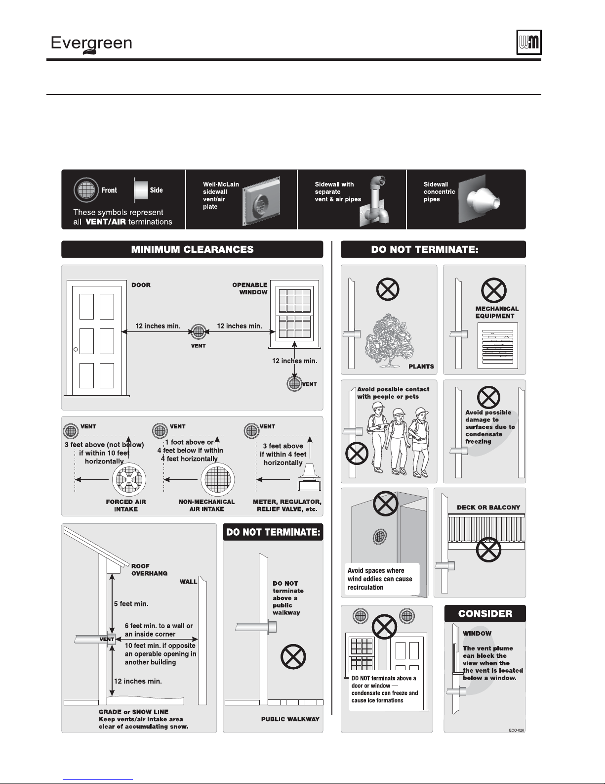
®
gas-fired water boiler — 70/110/155 Boiler Manual
Vent termination requirements
Figure 24 The vent termination must be located to meet all requirements below (also applies to vertical vent terminations). The minimum distance from
adjacent public walkways, adjacent buildings, openable windows and building in the National Fuel Gas Code, ANSI Z223.1/NFPA 54 and/or
the Natural Gas and Propane Installation Code, CAN/CSA B149.1. The vent termination clearances below are for U.S.A., for Canadian vent
termination clearances please refer to the requirements of CAN/CSA B149.1 Natural Gas and Propane Installation Code. Consideration
should be given to avoid possible damage caused by vent plumes and condensate when choosing a venting confi guration and location.
Maintain a minimum clearance of 4 ft. (1.22m) horizontally from, and in no case above or below, unless a 4 ft. (1.22m) horizontal distance
is maintained, from electrical meters, gas meters, regulators, and relief equipment.
26
Part number 550-100-191/0917
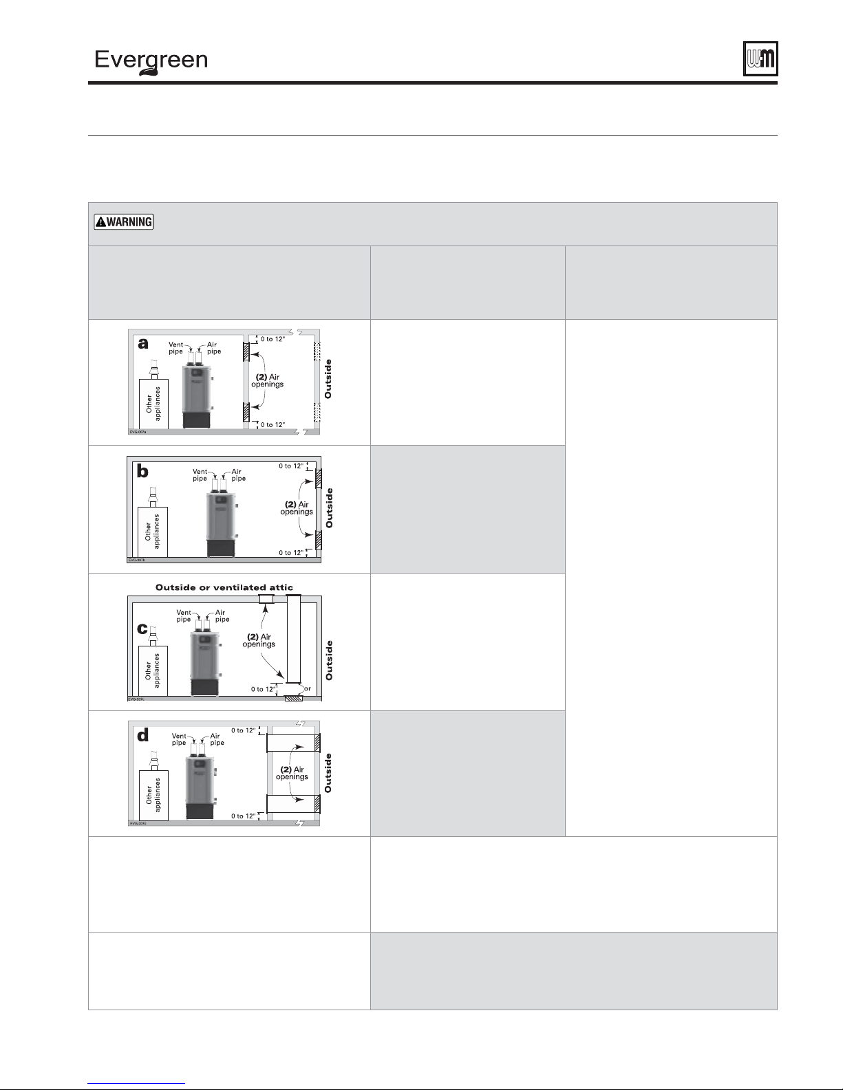
®
gas-fired water boiler — 70/110/155 Boiler Manual
Boiler room air openings
Figure 25 Combustion and ventilation air openings for Direct Vent installations, also follow the National Fuel Gas Code,
ANSI Z223.1/NFPA 54 - latest edition, and/or Natural Gas and Propane Installation Code, CAN/CSA B149.1 or
applicable provisions of the local building codes.
The Evergreen® boiler CANNOT be in the same space with other appliances if clearances around the Evergreen®
are less than the recommended service clearances shown in Figure 1, page 9 .
Air openings
The required air opening sizes below are FREE AREA,
after reduction for louver obstruction. Note the
exception below for large spaces.
®
Evergreen
boiler
WITH other
appliances in room
TWO openings, each at least:
1 square inch per 1,000 Btuh
of all other appliances in the room
(Unless specifi ed otherwise by
appliance manufacturer)
TWO openings, each at least:
1 square inch per 4,000 Btuh
of all other appliances in the room
ONE opening **, each at least:
1 square inch per 3,000 Btuh
of all other appliances in the room
(Unless specifi ed otherwise by
appliance manufacturer)
TWO openings, each at least:
1 square inch per 4,000 Btuh
of all other appliances in the room
ONE opening **, each at least:
1 square inch per 3,000 Btuh
of all other appliances in the room
(Unless specifi ed otherwise by
appliance manufacturer)
— OR —
— OR —
Evergreen® boiler
WITHOUT other
appliances in room
NO openings are required if the
boiler installation provides at least the
recommended service clearances
shown in
If the space is smaller than
Figure 1, page 9 , provide openings
ONLY as shown in
Each opening must have a free
area no less than 1 square inch per
1,000 Btuh input of the boiler.
Figure 1, page 9 .
Figure 2, page 9 .
** NOTICE:
Requirements for using the SINGLE air opening
option.
SPECIAL EXCEPTION FOR LARGE SPACES
(
EVG WITH other appliances in room only):
Part number 550-100-191/0917
TWO openings, each at least:
1 square inch per 2,000 Btuh
of all other appliances in the room
ONE opening **, each at least:
1 square inch per 3,000 Btuh
of all other appliances in the room
(Unless specifi ed otherwise by
appliance manufacturer)
A single combustion air opening can be used for cases b, c or d above (EVG with
other appliances in room only), sized as listed, provided that:
• The single opening must communicate directly to the outdoors or to a space that
communicates directly with outdoors (NOT to an interior space).
• The top of the opening must be within 12 inches of the ceiling.
• The free area of the opening must be at least equal to the sum of the areas of all
equipment vent connectors in the space.
NO combustion air openings are needed if the boiler (and other appliances) are
installed in a space with a volume NO LESS than 50 cubic feet per 1,000 Btuh of all
appliances in the space. That is, total the input of all appliances in MBH (1,000’s of
Btuh), then multiply this total times 50. The building MUST NOT be of tight construction.
Example: For a total input of 500 MBH (500,000 Btuh), the minimum volume would be
50 x 500 = 25,000 cubic feet.
— OR —
27
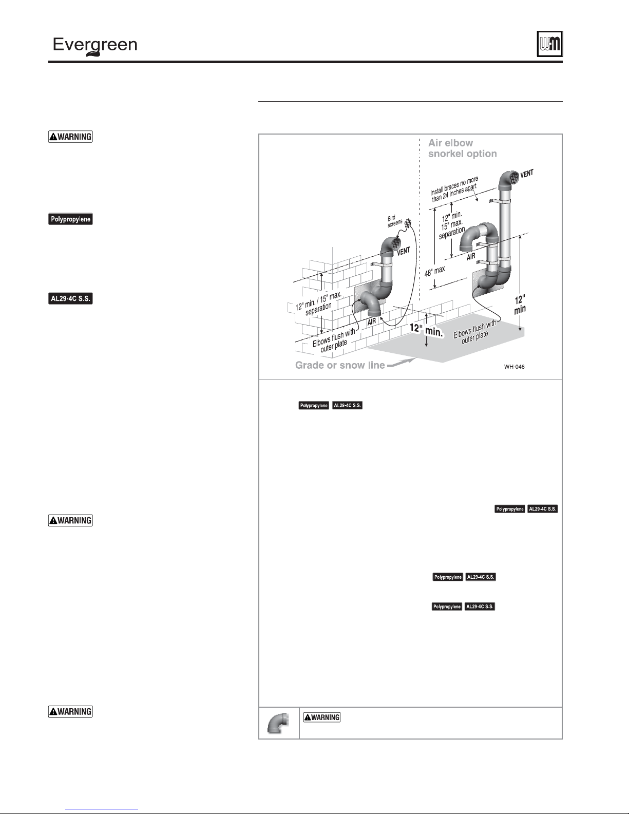
®
gas-fired water boiler — 70/110/155 Boiler Manual
DIRECT VENT — Sidewall with separate pipes
Allowable vent/air pipe materials &
lengths
Use only the vent materials and kits
listed in Figure 23, page 24 . Provide
pipe adapters if specifi ed.
1. Locate the termination such that the total air
piping and vent piping from the boiler to the
termination will not exceed the maximum
length given in Figure 22, page 23 .
For polypropylene applications,
comply with any additional
requirements in the vent system
manufacturer’s instructions. Provide
3" PVC transition pieces at the boiler
vent and air connections. Install a
locking collar at every joint.
For AL29-4C vent pipe applications,
comply with any additional
requirements in the vent system
manufacturer’s instructions.
Provide a 3" PVC transition piece
at the boiler vent connection. The
air piping must be PVC or CPVC.
Provide a 3" PVC transition piece
at the boiler air connection if using
2" air piping.
Determine termination location
1. The air and vent terminations must be installed
as shown in Figure 26 and Figure 28, page 29 .
2. The terminations must comply with clearances
and limitations shown in Figure 24, page 26 .
3. Locate the terminations so they are not likely
to be damaged by foreign objects, such as
stones or balls, or subject to buildup of leaves
or sediment.
Do not exceed the maximum
lengths of the outside vent piping
shown in Figure 26 . Excessive
length exposed to the outside could
cause freezing of condensate in the
vent pipe, resulting in potential
boiler shutdown. In extremely cold
climates, install an insulated chase
around the vent piping, particularly
if using longer lengths. The chase
must allow for inspection of the
vent pipe, and insulation must be
protected from water.
Multiple vent/air terminations
1. When terminating multiple boilers, terminate
each vent/air connection as described in this
manual.
All vent pipes and air inlets must
terminate at the same height to
avoid possibility of severe personal
injury, death or substantial property
damage.
Figure 26 INSTALLATION SEQUENCE — Separate pipes sidewall
Step 1 Read and follow all instructions in this manual. DO NOT proceed with
Step 2 Install the boiler in a location that allows proper routing of all vent and air
Step 3 Make sure the selected sidewall termination location complies with
vent/air installation until you have read page 22 through page 27 .
See notices at left.
piping to the selected sidewall location.
Figure 24, page 26 . (Multiple boiler sidewall plates must also comply with
Figure 27, page 29 .)
Step 4 Use only the vent materials listed in Figure 23, page 24 . Provide pipe adapters
Step 5 Prepare the sidewall penetrations and secure the sidewall plates as instructed
Step 6 The air piping must terminate in a down-turned elbow as shown above.
Step 7 Install vent and air piping between the boiler and the sidewall openings.
Step 8 Install pipe supports every 5 feet on both the horizontal and vertical runs.
Step 9 Attach the vent termination exterior piping: Use either of the confi gurations
Step 10 The vent and air pipes may run up as high as 4 feet with no enclosure.
Step 11 External venting greater than 4 feet requires an insulated enclosure around
where required. Vent piping and air piping lengths must not exceed the
values shown in
in this section. See “Prepare wall penetrations” on page 29 .
See notices at left.
The vent piping must terminate in an elbow pointed outward or away
from the air inlet as shown above. See illustration above.
Slope horizontal piping downward toward the boiler at least 1/4 inch per
foot. See
Install a hanger support within 6 inches of any upturn in the piping, or per
vent pipe manufacturer’s instructions.
shown above, as needed to ensure clearance above grade or snow line.
The vent and air pipes must be secured with braces, and all clearances and
lengths must be maintained. Space braces no further than 24 inches apart.
the vent and air pipes. The vent and air terminations must exit through
the enclosure as shown in the illustration above, maintaining all required
clearances.
Figure 22, page 23 .
page 39 for general guidelines. See notices at left.
See notices at left.
USE SWEEP ELBOWS FOR ALL VENT AND AIR PIPING
— DO NOT use short radius elbows for vent or air piping. Boiler
performance could be affected.
28
Part number 550-100-191/0917
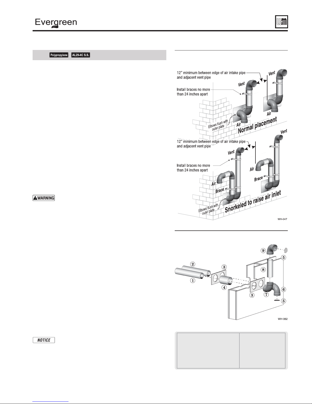
®
gas-fired water boiler — 70/110/155 Boiler Manual
DIRECT VENT — Sidewall with separate pipes (continued)
See notices on previous page.
2. Place wall penetrations to obtain minimum clearances shown in
Figure 27 for U. S. installations. For Canadian installations, provide
clearances required by CSA B149.1 or B149.2 Installation Code and
a ULC S636 compliant vent kit.
3. The air inlet of a boiler is part of a direct vent connection. It is
not classifi ed as a forced air intake with regard to spacing from
adjacent boiler vents.
Prepare wall pe netrations
1. Air pipe penetration:
a. Cut a hole for the air pipe. Size the air pipe hole as close as
desired to the air pipe outside diameter.
2. Vent pipe penetration:
a. Cut a hole for the vent pipe. For either combustible or
noncombustible construction, size the vent pipe hole at least
0.4" larger than the vent pipe diameter.
b. Insert a corrosion resistant metal thimble in the vent pipe hole
as shown in Figure 28 .
3. Use the provided paper template for correct location of hole centers.
4. Use of a sidewall termination plate is REQUIRED.
a. Kits for several vent sizes are available from Weil-McLain.
See “VENT/AIR PARTS AND KITS” on page 127 .
b. Plate may be fi eld fabricated from corrosion resistant material
of suffi cient strength. Plate must allow venting to maintain
minimum clearance to combustibles.
Ensure that the plate material is strong enough to prevent
the termination from being pushed inward if struck or
pushed from the outside.
5. Follow all local codes for isolation of vent pipe when passing
through fl oors or walls.
6. Seal exterior openings thoroughly with exterior caulk.
Figure 27
Multiple separate pipes sidewall terminations
— maintain vertical spacing between vent and
air fi ttings shown in Figure 26, page 28
Termination and fi ttings
1. Prepare the vent termination elbow and the air termination elbow
by inserting bird screens. (See Figure 26, page 28 .) Bird screens
must be purchased separately. See the parts list at the end of this
manual for part numbers.
2. Secure the elbows so they will butt against the sidewall termination
plate.
3. When completed, the air termination coupling must be oriented
at least 12 inches below the vent termination and at least 12 inches
above grade or snow line as shown in Figure 26, page 28 .
4. You can orient the vent termination elbow either directly
outward or 90 degrees away from the air inlet elbow as shown in
Figure 26, page 28 .
5. Maintain the required dimensions of the fi nished termination
piping as shown in Figure 26, page 28 .
6. For multiple boiler terminations, see Figure 27 .
7. Do not extend exposed vent pipe outside of building more than
shown in this document. Condensate could freeze and block vent
pipe.
If extending the vent and air pipes out from the wall,
install a coupling on each pipe. Mount the piping with
the coupling fl ush with the outer plate.
Figure 28 Sidewall termination assembly — using
separate pipes
1 Vent piping
2 Air piping
3 Sidewall termination plates: for 3" PVC,
use plates supplied with boiler in W-M
vent/air plate kit; for 3" AL29-4C or 2" PVC,
purchase optional sidewall separate pipes
plate kit
4 Corrosion resistant thimbles,
by installer
5 Bird screen, by installer
6 Air inlet elbow
7 Elbow
8 Nipple
9 Elbow (vent termination)
Part number 550-100-191/0917
29
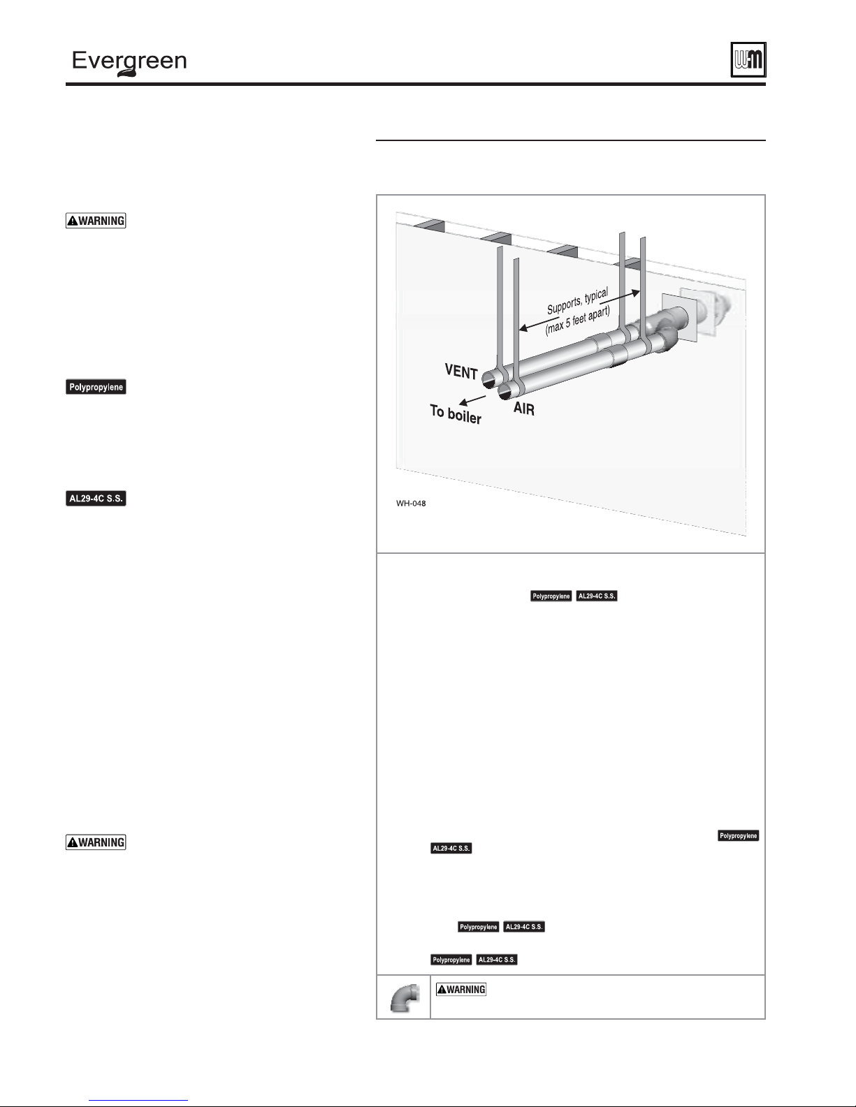
®
gas-fired water boiler — 70/110/155 Boiler Manual
DIRECT VENT — Sidewall concentric
Allowable vent/air pipe materials &
lengths
1. The concentric termination kit must be purchased
separately.
Use only the vent materials and kits
listed in Figure 23, page 24 . Provide pipe
adapters if specifi ed.
2. Locate the termination such that the total air piping
and vent piping from the boiler to the termination
will not exceed the maximum length given in
Figure 22, page 23
.
3. This termination requires a 45-degree elbow that
is not supplied with the termination kit. The
maximum vent/air pipe lengths include allowance
for this elbow.
For polypropylene applications, comply
with any additional requirements in the
vent system manufacturer’s instructions.
Provide 3" PVC transition pieces at the
boiler vent and air connections and at the
termination if using a 3" PVC concentric
vent kit. Install a locking collar at every
joint.
For AL29-4C vent pipe applications,
comply with any additional requirements
in the vent system manufacturer’s
instructions. Provide a 3" PVC transition
at the boiler vent connection. Air pipe
must be PVC or CPVC. Provide a 3" PVC
transition at the boiler air connection
if using 2" air pipe. Provide transition
pieces to PVC at the vent and air pipe
termination connections.
Determine termination location
1. The concentric termination kit must be installed
as shown in Figure 31, page 31 .
2. The termination must comply with clearances and
limitations shown in
Figure 24, page 26
.
3. Locate the termination so it is not likely to be
damaged by foreign objects, such as stones or balls,
or subject to buildup of leaves or sediment.
Multiple vent/air terminations
1. When terminating multiple boilers, install each
concentric termination as described in this manual.
All vent pipes and air inlets must
terminate at the same height to avoid
possibility of severe personal injury,
death or substantial property damage.
2. Place wall penetrations to obtain minimum
clearance as shown in Figure 30, page 31 for U. S.
installations. For Canadian installations, provide
clearances required by CSA B149.1 or B149.2
Installation Code and a ULC S636 compliant vent
kit.
3. The air inlet of a boiler is part of a direct vent
connection. It is not classifi ed as a forced air intake
with regard to spacing from adjacent boiler vents.
Figure 29 INSTALLATION SEQUENCE — Concentric horizontal
Step 1 Read and follow all instructions in this manual. DO NOT proceed
Step 2 Install the boiler in a location that allows proper routing of all vent
Step 3 Make sure the selected sidewall termination location complies with
with vent/air installation until you have read page 22
through page 27 .
and air piping to the selected sidewall location.
See notices at left.
Figure 24, page 26 . (Multiple boiler concentric terminations must also
comply with Figure 30, page 31 .)
Step 4 Use only the vent materials listed in Figure 23, page 24 . Provide pipe
Step 5 Vent piping and air piping lengths must not exceed the values shown
Step 6 The concentric termination must be assembled and installed before
Step 7 Prepare the sidewall penetration — assemble the concentric
Step 8 Install vent and air piping between the boiler and the concentric vent/
Step 9 Install pipe supports every 5 feet on both the horizontal and vertical
Step 10 Install a hanger support within 6 inches of any upturn in the piping.
adapters where required.
Figure 22, page 23 .
in
piping from the boiler to the termination.
termination kit and secure the cover plates as instructed in this section.
Provide the supports indicated and mount the termination assembly.
See “Install termination — concentric pipes” on page 31 .
air termination. Slope horizontal piping downward toward the boiler
at least 1/4 inch per foot. See page 39 for general guidelines.
runs.
See notices at left.
See notices at left.
See notices at left.
USE SWEEP ELBOWS FOR ALL VENT AND AIR
PIPING — DO NOT use short radius elbows for vent or
air piping. Boiler performance could be affected.
30
Part number 550-100-191/0917
 Loading...