

Page 1
EGHEGH
EGH
EGHEGH
Control SupplementControl Supplement
Control Supplement
Control SupplementControl Supplement
EGH-105 to EGH-125 Series 4
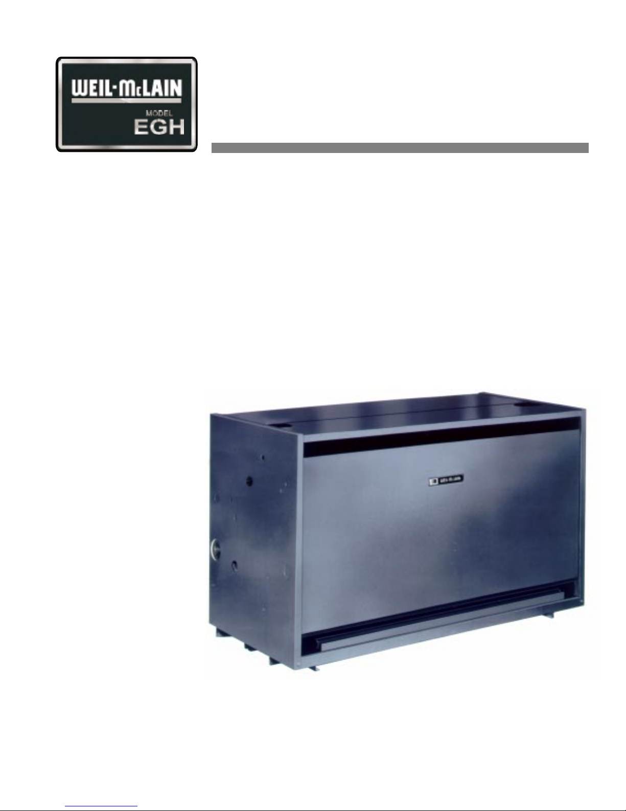
Gas-Fired Boiler
Natural gas
CSD-1
control system
‡
‡ For propane boilers, install EGH propane conversion kit in addition to following the
instructions in this Control Supplement.
Part No. 550-110-677/0299
Page 2
EGH-105 to EGH-125 EGH-105 to EGH-125
EGH-105 to EGH-125 Control Supplement
EGH-105 to EGH-125 EGH-105 to EGH-125
Please read this page first
Hazard definitions
To the installer:
The following terms are used throughout this Control Supplement to bring attention to the
presence of hazards of various risk levels or to important information concerning the life of the
product.
Indicates presence of hazards that will cause severe personal injury, death or
substantial property damage.
Indicates presence of hazards that can cause severe personal injury, death or
substantial property damage.
Indicates presence of hazards that will or can cause minor personal injury or
property damage.
Indicates special instructions on installation, operation or maintenance that
are important but not related to personal injury or property damage.
This Control Supplement must only be used by a qualified installer/service
technician. Read these instructions completely before beginning the
installation. Failure to follow these instructions can cause severe personal
injury, death or substantial property damage.
This Control Supplement is for CSD-1 controls on EGH-105 to EGH-125
boilers only, specifically for:
• Water boilers without tankless heater. (CSD-1 is not available for
water boilers with tankless heater.)
• Steam boilers with or without tankless heater.
This document is only intended as a supplement to the EG, PEG and EGH
(Series 4) Boiler Manual
Follow all instructions in the EGH Manual in addition to the instructions in
this Control Supplement.
(referred to in this Supplement as the EGH Manual).
Contents
The installation must conform to the requirements of the authority having
jurisdiction, or, in the absence of such requirements, to the National Fuel Gas
Code, ANSI Z-223.1/NFPA-54 (latest edition). Where required by the authority
having jurisdiction the installation must conform to the American Society of
Mechanical Engineers (ASME) Safety Code for Controls and Safety Devices
for Automatically-Fired Boilers, Number CSD-1.
I. ................. Installation .......................................................................... 4
II. ................ Piping connections ............................................................. 6
III. ............... Install boiler controls ......................................................... 6
IV. ............... Optional heaters ................................................................7
V. ................ Gas piping ........................................................................... 8
VI. .............. Wiring ..................................................................................8
VII. ............. Final adjustments ............................................................. 22
VIII. ............ Check-out procedure .......................................................24
IX. .............. Service and maintenance ................................................ 31
X. ............... Replacement parts ........................................................... 32
2
Part Number 550-110-677/0299
Page 3
CSD-1 control system — Natural gas
Carton guide
Table 1 Boiler cartons
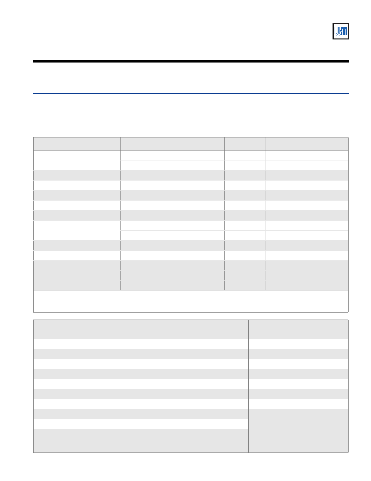
Verify that the correct cartons are available bef ore beginning assembly. Note that the Base assembly and Trim &
controls cartons for CSD-1 are special. The CSD-1 ignition control panel (in Base assembly carton) consists of ignition
control module, impulse relay and lighted push-button switch mounted and wired on a panel base.
Carton Comments EGH-105 EGH-115 EGH-125
Section assembly (a)
Base assembly (b) CSD-1 381-700-400 381-700-402 381-700-404
Base panels 381-700-250 381-700-255 381-700-260
Jacket 411-800-280 411-800-290 411-800-300
Collector hood 450-014-752 450-014-753 450-014-754
Draft hood 450-206-242 450-206-243 450-206-244
Float low water cutoff (steam)
Vent damper (optional) (c) 381-800-446 381-800-447 381-800-447
T ankless heater (optional) Steam boilers only 386-700-350 386-700-350 386-700-350
T rim & controls (see below)
Note a — CSD-1 water boilers cannot be equipped with a tankless heater.
Note b — Base assembly includes burner tubes, gas train components, pilot assembly and control panel (with ignition control).
Note c — EGH vent dampers meet ASME CSD-1 requirements (paragraph CF-210(c)) because they comply with ANSI Z21.13.
Steam trim and control carton
Gravity return
With tankless opening 321-711-120 321-711-130 321-711-140
Without tankless opening 321-711-125 321-711-135 321-711-145
Gravity return (M&M #67W-1) 381-700-341 381-700-341 381-700-341
Pumped return (M&M #42-A) 511-114-531 511-114-531 511-114-531
Water , CSD-1 — or — 381-700-406 381-700-406 381-700-406
Steam, CSD-1, gravity return — or — 381-700-408 381-700-408 381-700-408
Steam, CSD-1, pumped return 381-700-410 381-700-410 381-700-410
Steam trim and control carton
Pumped return
Water trim carton
Pressure limit control, automatic reset Pressure limit control, automatic reset Aquastat, automatic reset
Pressure limit control, manual reset Pressure limit control, manual reset Aquastat, manual reset
Probe low water cutoff, manual reset Probe low water cutoff, manual reset Probe low water cutoff, manual reset
Transformer/relay Transformer/relay Transformer/relay
Wire harness, steam gravity return Wire harness, steam pumped return Wire harness, water
Crimp spade wire terminations Crimp spade wire terminations Crimp spade wire terminations
ASME Relief valve ASME Relief valve ASME Relief valve
Pressure gauge Pressure gauge
Gauge glass and valves Gauge glass and valves
Brass cross, brass nipple, bushings (3) and
siphons (3) for mounting pressure controls
and gauge
Part Number 550-110-677/0299
Brass cross, brass nipple, bushings (3)
and siphons (3) for mounting pressure
controls and gauge
Pressure/temperature gauge
3
Page 4
EGH-105 to EGH-125 EGH-105 to EGH-125
EGH-105 to EGH-125 Control Supplement
EGH-105 to EGH-125 EGH-105 to EGH-125
InstallationI
Place the boiler
Install gas train
Refer to the EGH Manual. Read Section I and follow all of its guidelines. Complete the
following steps of Section I of the EGH Manual:
• Placing the boiler
• Installation of optional water heaters, steam boilers only (including pages 13–14)
• Hydrostatic pressure test
• Installation of flue collector hood
• Installation of (burner) drawer assembly and front access panel and back base channel
• Jacket installation
• Draft hood installation
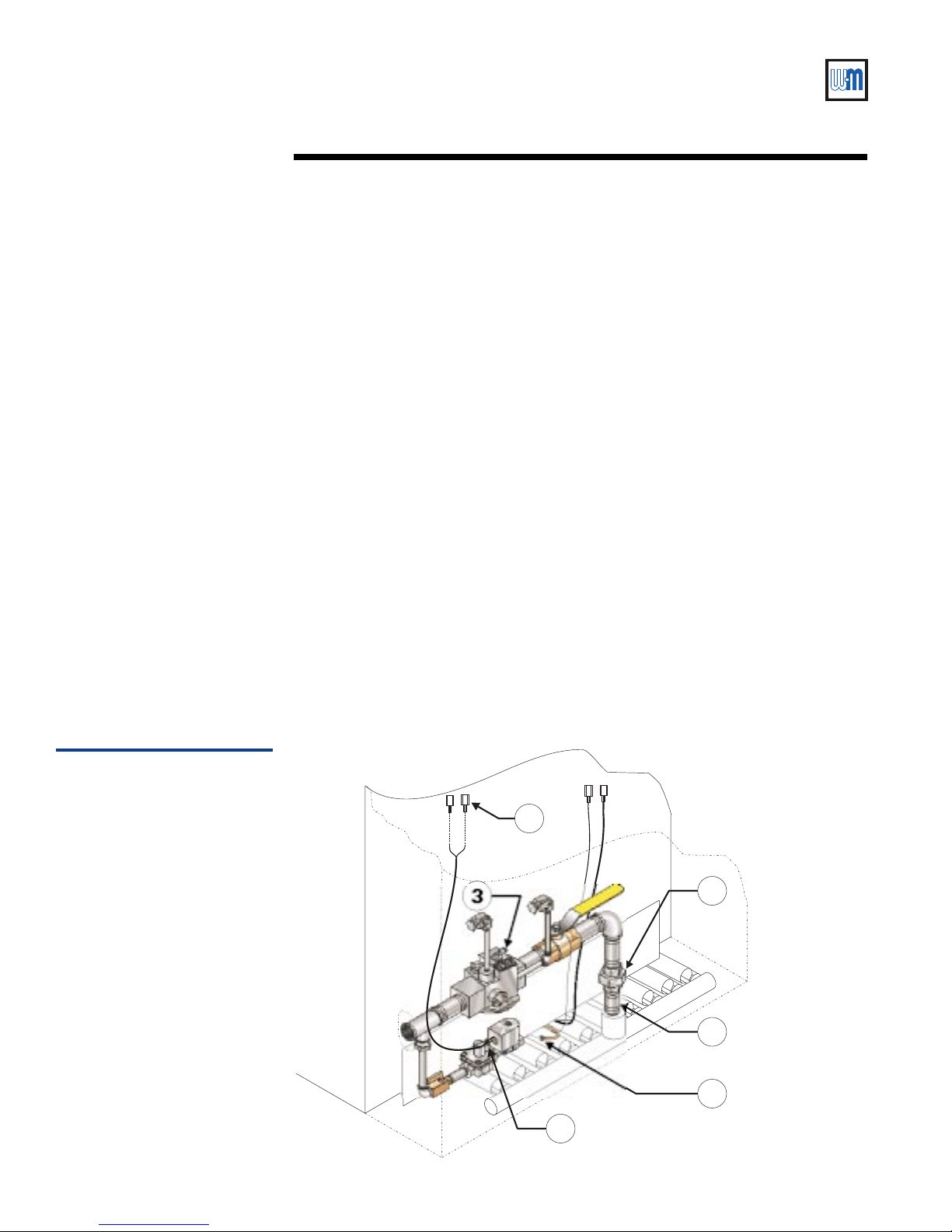
Connect gas train assembly to burner manifold:
• Apply pipe dope to 1" nipple for insertion into burner manifold coupling (Figure 1,
item 1). Insert and tighten nipple.
• Pipe lower half of ground joint union to the 1” nipple (Figure 1, item 2).
• Knock out the jacket gas valve opening on the desired side of the boiler (may be routed
through either right or left side).
• Place gas train in position (either routed to the left, as shown, or to the right) and tighten
the ground joint union loosely. Position the gas train assembly and tighten the union.
• Connect vent lines (routed to outside per code requirements) to ¼" tubing vent
connections on main gas valve and pilot gas pressure regulator (Figure 3, item 3).
• Connect pilot gas tubing (1/8" aluminum) to adapter in pilot gas valve outlet
(Figure 1, item 4).
• Crimp connect two ¼" spade terminals (provided) to ends of pilot gas valve wires
(Figure 1, item 5).
Install vent/breeching
Figure 1
Gas train assembly
Install vent system and breeching per EGH Manual Section I. If optional vent damper is used,
install vent damper (using Section I of this Supplement) before installing breeching.
5
3
2
1
4
3
677-09
4
Part Number 550-110-677/0299
Page 5
CSD-1 control system — Natural gas
Install optional vent damper (if supplied)
If not installing a vent damper, proceed to next section
(Piping connections).
Once a vent damper has been
operated on an EGH boiler, the boiler
will no longer operate without a
damper installed.
Only dampers listed in the
Replacement parts list in this
Supplement are certified for use with
EGH Series 4 boilers. Any other
damper installed could cause severe
personal injury or death.
Minimum clearances — Provide a minimum of 6" between
the damper and any combustible material. (Provide a
minimum of 46" between EGH jacket top and a
combustible ceiling.)
Damper must be installed directly on
top of draft hood so that it serves
only that boiler. DO NOT modify
draft hood or damper, or make
another connection between draft
hood and damper or boiler. This will
void AGA/CGA certification and will
not be covered by Weil-McLain
warranty. Any changes will cause
severe personal injury, death or
substantial property damage.
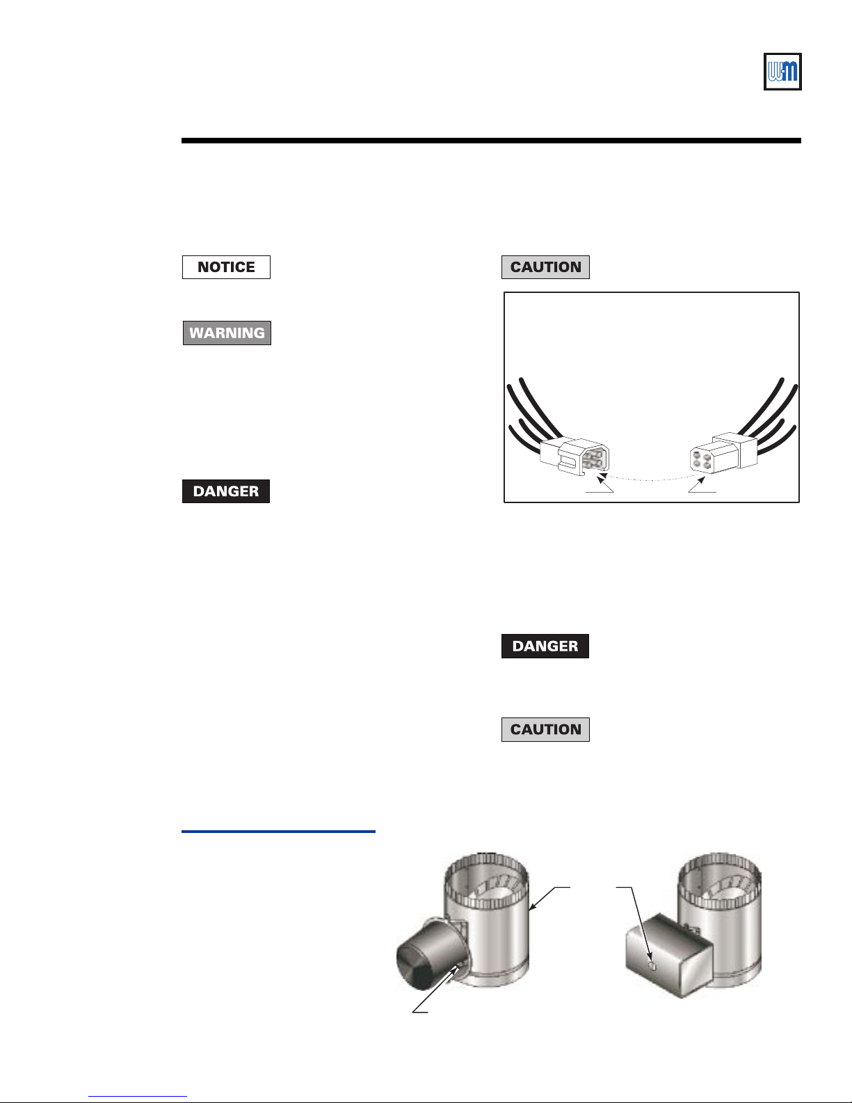
Install damper directly on top of draft hood, with arrow
pointing straight up. Install so the damper blade indicator
is visible to the user. See Figure 2.
Screws or rivets used to secure the damper to the vent
pipe and the draft hood must not interfere with rotation
of the damper blade.
Install damper harness between damper actuator and
knockout in right top of boiler jacket. Knock out opening
in jacket top and install strain relief bushings in jacket
and actuator wiring openings. Insert wires and secure
strain relief clamps. See Figure 6, 8, or 10 as applies.
Keep wiring harnesses clear of all hot
surfaces.
WARNING
LINE UP KEYWAY WHEN
CONNECTING PLUGS.
FORCING A MISMATCH
CAN CAUSE A
HAZARDOUS CONDITION.
Keyway Key
Read and apply the harness plug warning label (above)
so that it is visible after installation.
Remove dummy plug from damper connector in boiler
wiring harness. Plug damper harness receptacle into
damper harness plug. See Figure 6, 8, or 10 as applies.
By-passing (jumpering) damper will
cause flue products such as carbon
monoxide to escape into the house.
This will cause severe personal injury
or death.
After boiler has operated once, if
either end of harness is disconnected,
the system will shut down. The boiler
will not operate until the harness is
reconnected.
677-10
Vent damper assemblies
Part Number 550-110-677/0299
Figure 2
Effikal damper
Hold-open switch (Effikal only) —
Install damper so that switch is
visible and accessible to user.
Damper
blade
indicator
Johnson Controls damper
677-05
5
Page 6
EGH-105 to EGH-125 EGH-105 to EGH-125
Tapping Application W-M Part No.
D Boiler drain connection —
E ASME relief valve (per EGH manual) —
G Pipe to air vent or compression tank —
H Honeyw ell L4006E-1000 M/R limit 510-312-041
L Pressure/temperature gauge 510-218-097
S Temperature limit control, auto reset 510-312-209
V Gas supply connection (right or left) —
Not shown
McDonnell & Miller PS852M-24 M/R
probe LWCO (Mount in supply or
return piping, above top of boiler)
511-114-530
Plug all tappings not used.
EGH-105 to EGH-125 Control Supplement
EGH-105 to EGH-125 EGH-105 to EGH-125
Piping connectionsII
Connect steam (water) piping to the boiler per EGH Manual Section II.
Water boilers — make provision for mounting probe low water cutoff in the supply or return
piping, above the top of the boiler. The low water cutoff must be between the boiler and any
isolation valve(s).
Install boiler controls — water boilersIII
The controls may be mounted on either end of the boiler. Mount all controls
on the same end. The junction box (electrical entrance) must also be mounted
on the same end as the controls.
Install the probe low water cutoff in the supply or return piping, above the
top of the boiler. The low water cutoff must be mounted between the boiler
and any isolation valve(s) installed in the piping.
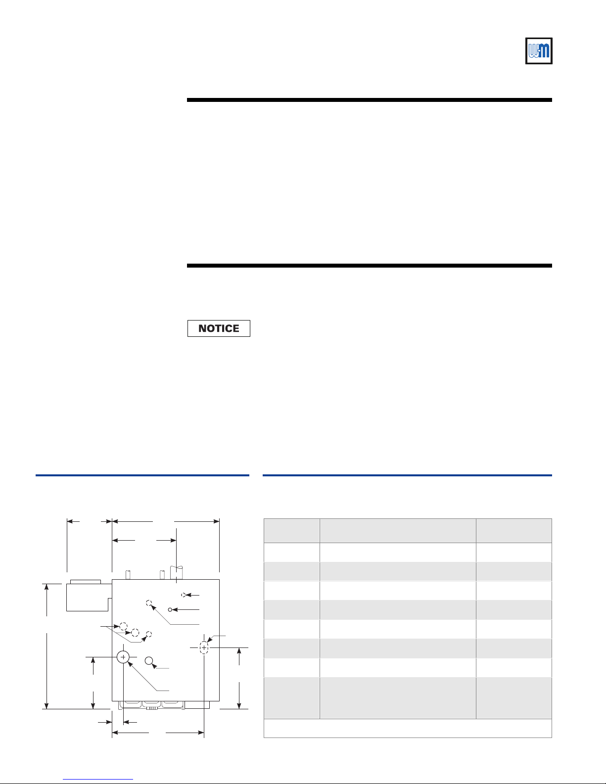
Install water trim components as required by ASME CSD-1, latest edition. See Figure 3 and
Table 2 for controls required and tapping usage. See Figure 6 for finished assembly.
Plug all unused tappings.
All piping and control connections must also comply with the EGH Manual.
Figure 3
Water boiler connections
5
11¾" 27 / "
16 / "
32¾"
Not
used
EG
8
3
16
Supply
L
S
H
V
Table 2
Water boiler connections
6
13½"
11
16
2/"
D
Return
24"
5
8
16/"
677-08
Part Number 550-110-677/0299
Page 7
CSD-1 control system — Natural gas
Install boiler controls — steam boilersIII
All water level controls must mount on the left end of the boiler. Failure to do
so could result in nuisance shutdowns and possible lockout on the manual
reset control due to water level variations from end to end. Substantial
property damage could result from freezing due to loss of heat.
All controls must mount on left end of the boiler. The correct tappings are
available only on the left end section.
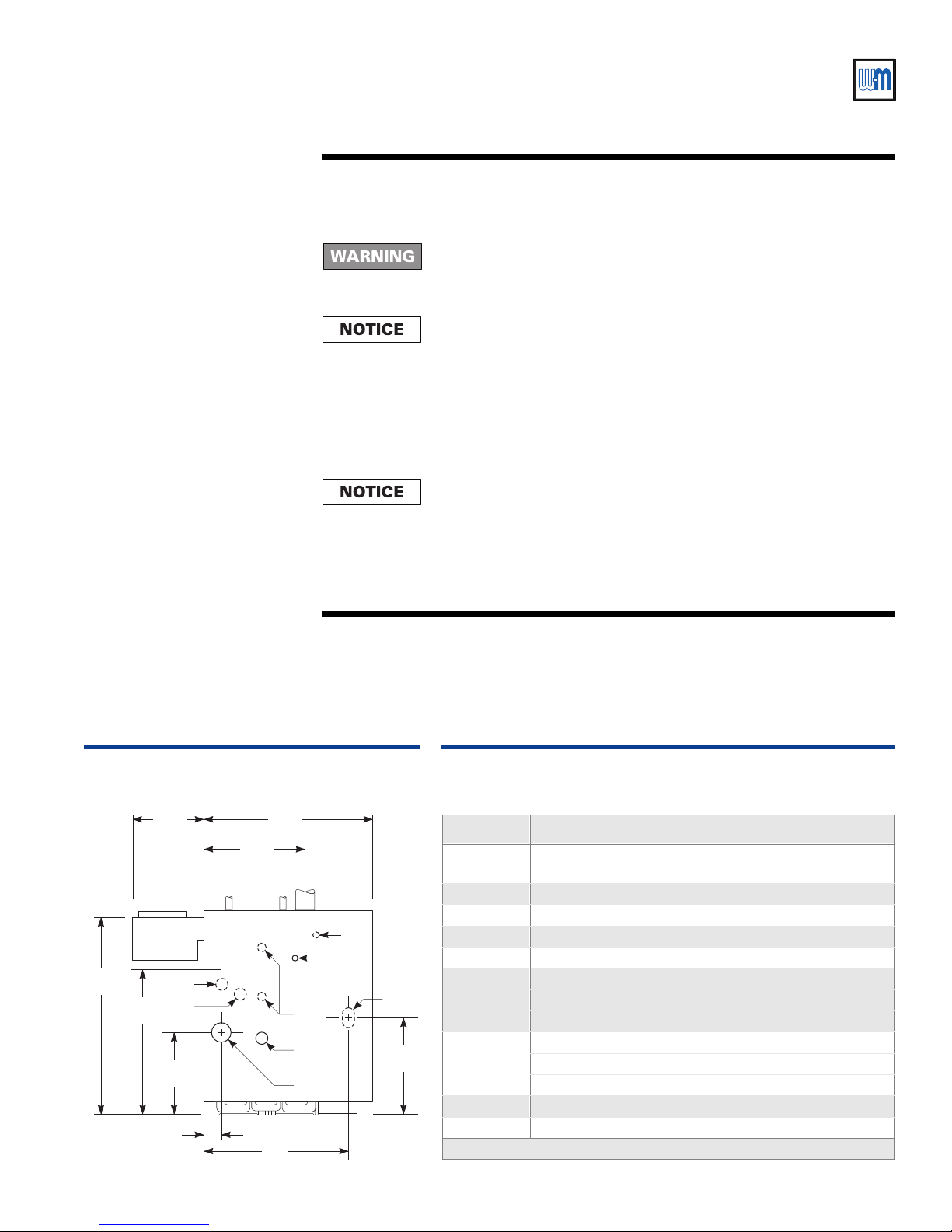
Install steam trim components as required by CSD-1, latest edition. See Figure 4 and Table 3.
See also Figure 8 or Figure 10 for finished assembly.
• CSD-1 requires two low water cutoffs (one manual reset) and two limit controls (one
manual reset) as shown in the illustration.
• For float type (automatic reset only) low water cutoffs other than those shown in this
Supplement, refer to EGH Manual for mounting and piping instructions.
Install a blowdown valve on any float type low water cutoff as described in
the EGH Manual, Section III.
Figure 4
Steam boiler connections
11¾" 27 / "
3
16 / "
EG
32¾"
23 / "
(Water line)
13
16
2/"
13½"
11
16
C
T
16
24"
Plug all unused tappings.
All piping and control connections must also comply with the EGH Manual.
Optional heaters — steam boilers onlyIV
Install optional tankless heater, if used, (steam boiler only) per EGH Manual Section IV.
Table 3
Steam boiler connections
5
8
H
D
Return
Supply
risers
L
S
V
5
16/"
677-07
Tapping Application W-M Part No.
T
C Not used — plug tapping —
D Drain connection (per EGH manual) —
E ASME relief valve (per EGH manual) —
G Not used - plug tapping —
H
8
L
S Skim tapping (per EGH manual) 510-312-209
V Gas supply connection (right or left) —
McDonnell & Miller PS852M-24 M/R
probe LWCO
Float LWCO, automatic reset — —
Gravity return — McD-M 67W-1 511-114-494
Pumped return — McD-M 42-A 511-114-531
Pressure gauge 510-218-045
Pressure limit, automatic reset 510-312-135
Honeywell L404C-1147 M/R limit 510-312-060
Plug all tappings not used.
511-114-530
Part Number 550-110-677/0299
7
Page 8
EGH-105 to EGH-125 EGH-105 to EGH-125
EGH-105 to EGH-125 Control Supplement
EGH-105 to EGH-125 EGH-105 to EGH-125
Gas pipingV
Size and connect gas supply piping per EGH Manual,
Section V.
The gas supply can enter from either the right or left
side of the jacket. Be sure the gas train is directed to the
correct side.
WiringVI
For your safety, turn off electrical
power supply before making any
electrical connections to avoid
possible shock hazard.
A strain relief bushing and adapter
must be used at each point where
wiring passes through the boiler
jacket or control cases to protect
wiring insulation.
Assembly illustrations and wiring
diagrams
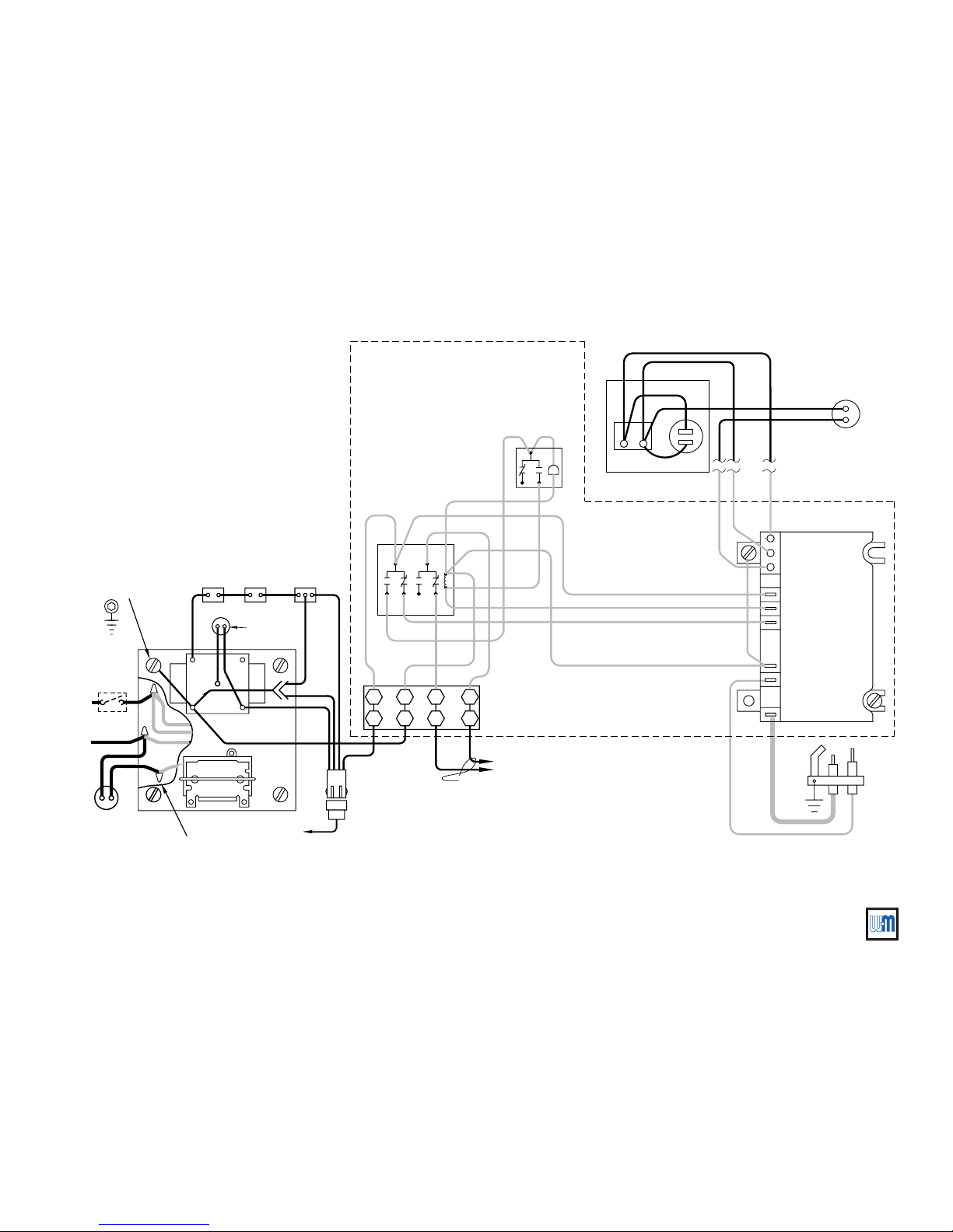
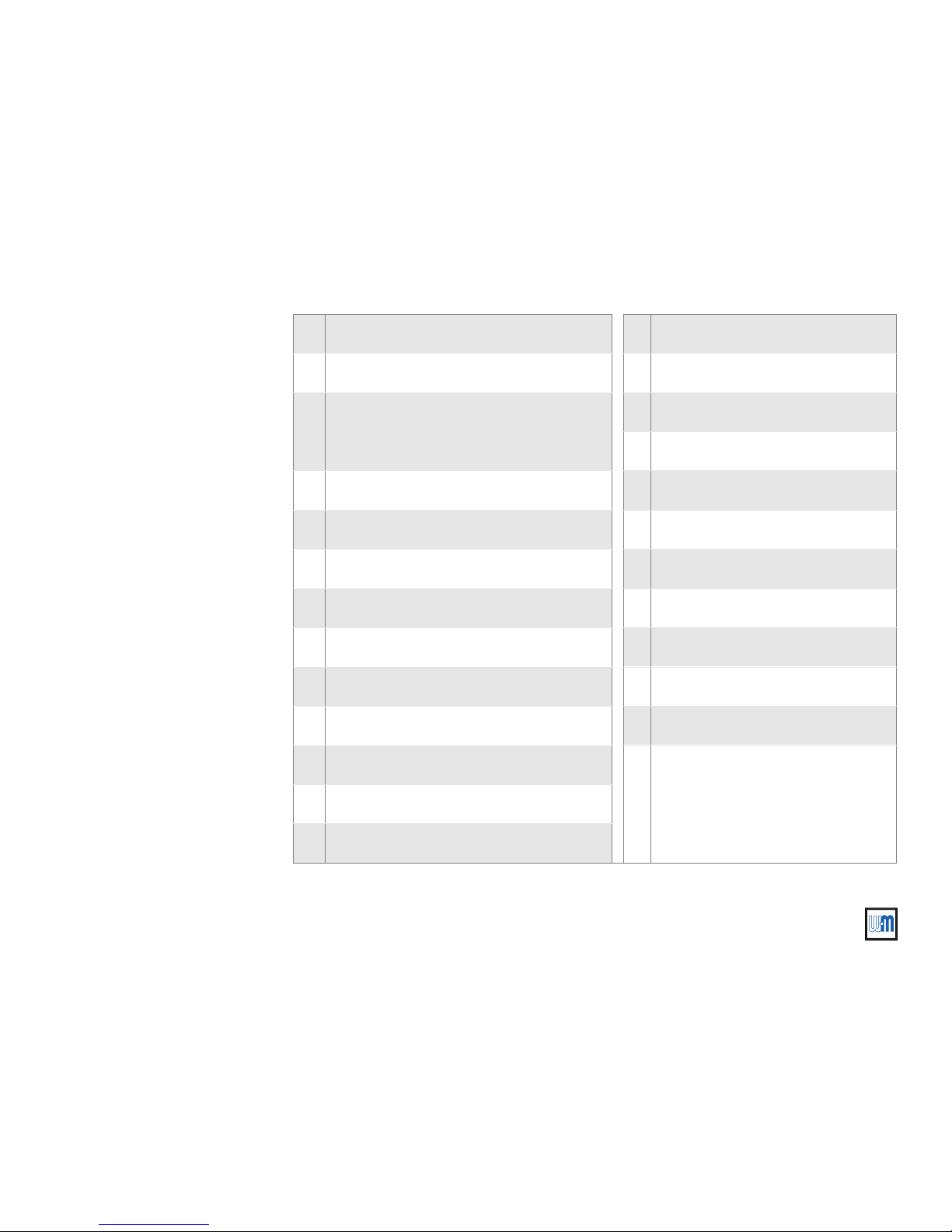
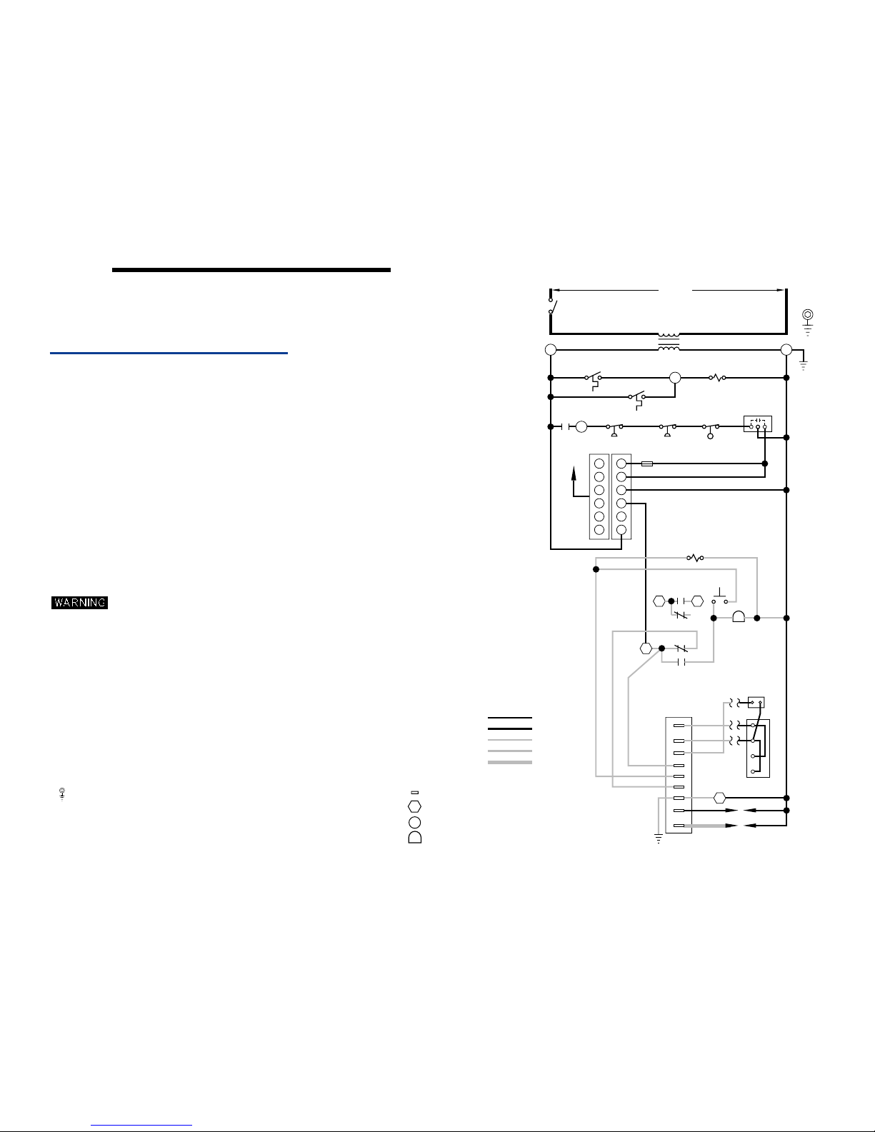
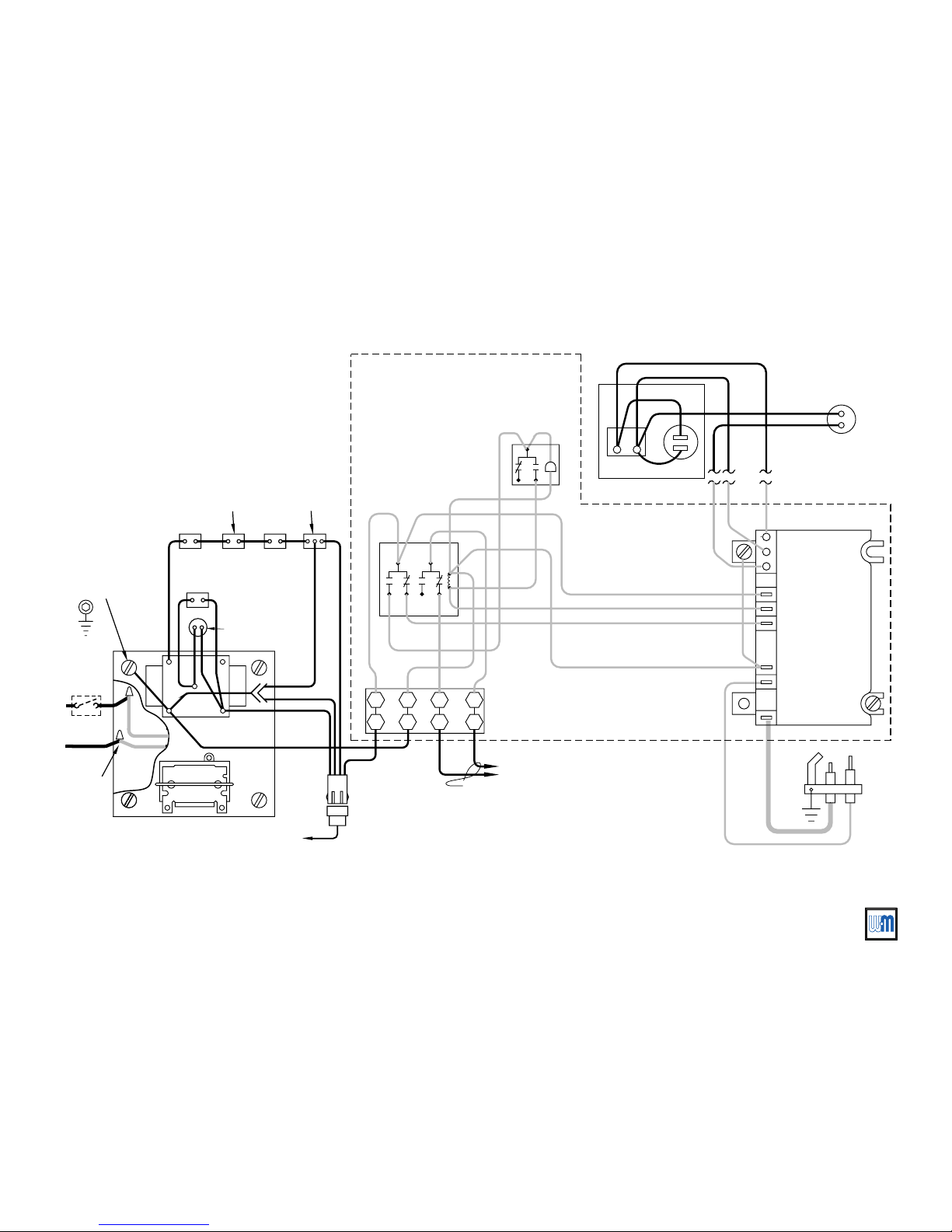
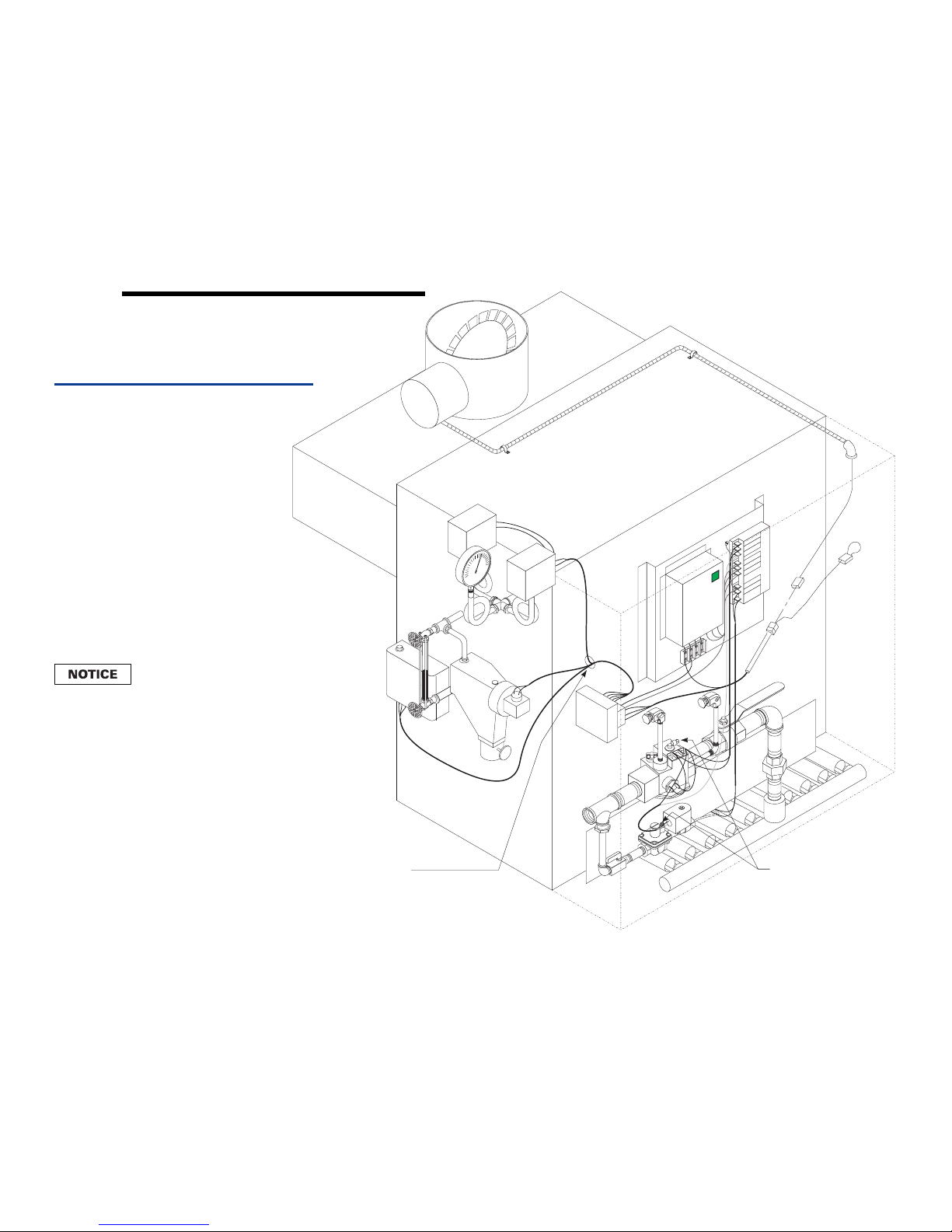
This Supplement contains three wiring diagrams and
associated assembly illustrations. Refer to the
following, as applicable:
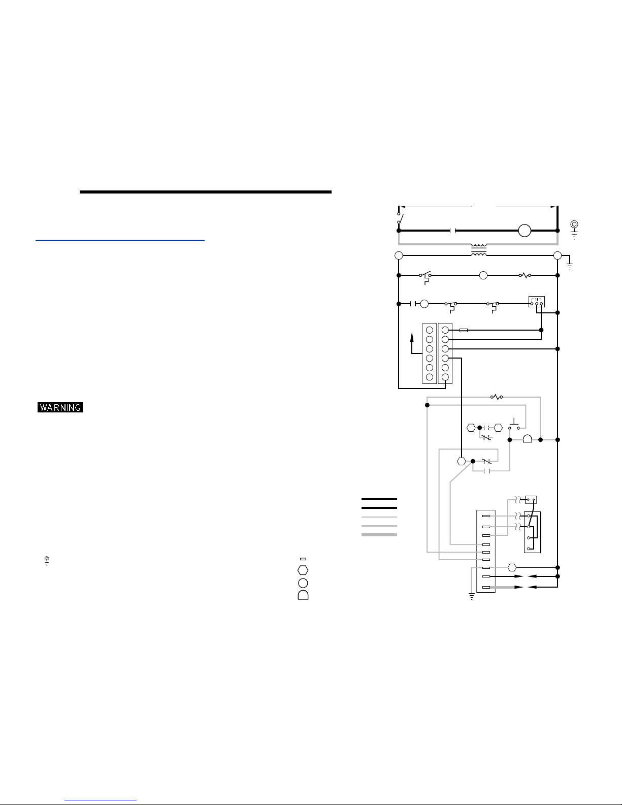
• Water boilers —Figures 5 and 6
• Steam boilers, gravity return — Figures 7 and 8
• Steam boilers, pumped return — Figures 9 and 10
General
Refer to EGH Manual, Section VI for further
information.
All wiring must be installed in accordance with the
requirements of the National Electrical Code and any
additional national, state or local code requirements
having jurisdiction. All line voltage wiring external to
boiler jacket must be N.E.C. class 1.
Provide a separate electrical circuit with a fused
disconnect switch (15 amp recommended) to supply
the boiler. Wiring to the boiler must be No. 14 gauge or
heavier, installed in conduit.
The boiler must be electrically grounded in accordance
with the National Electrical Code, ANSI/NFPA No. 70,
latest edition.
Support gas line securely. Do not
support weight of gas line off of boiler
gas train.
Purge air from gas piping and perform gas line and gas
connection leak test per Section V of the EGH Manual.
Use 105 °C thermoplastic wire, or equivalent, if any
original wire must be replaced (except for pilot spark
and sense wires).
Wiring procedure
1. Mount all controls as directed in Section III of this
Supplement. Refer to the assembly illustration for
the type of boiler installed (Figure 6, 8 or 10).
2. Mount the junction box supplied with the boiler on
the inside left (or right) side of the jacket as shown
in the assembly illustration (using screws and nuts
provided). Mount the junction box on the same
end of the boiler as the controls will be
mounted
3. Attach the transformer/relay to the junction box.
4. Mount the CSD-1 control panel on the jacket
interior panel as shown in the appropriate
assembly illustration (Figure 6, 8 or 10), using
screws and nuts provided.
5. Crimp connect ¹⁄₄" spade terminals (provided) to
the pilot gas valve wires if not already done in
Section I of this Supplement.
6. If optional vent damper is installed, make sure
damper harness has been routed through a strain
relief bushing in the jacket and damper actuator as
directed in Section I of this Supplement. Secure
damper harness conduit to top of jacket with
clamps provided.
7. The main gas valve wires are pre-attached to the
CSD-1 control panel. The spark and sense wires
from the pilot are factory installed to the pilot.
Connect these wires as shown in the wiring
diagram.
8. Use the wiring harness provided with the boiler to
complete wiring of the remaining components
according to the appropriate wiring diagram and
assembly illustration.
.
8
Part Number 550-110-677/0299
Page 9
CSD-1 control system — Natural gas
Wiring — sequence of operationVI
General
The following sequence of operation applies to all wiring diagrams in this Supplement — both
water and steam.
Call for heat
On a call for heat (from thermostat or operating control):
1. Limit control and water level control contacts are assumed closed.
2. Vent damper (if provided) will open.
3. Ignition control checks for signal at pilot. (No signal should be present.)
If no signal is sensed
a. Pilot solenoid opens.
b. Pilot ignition spark begins.
c. Pilot ignites.
d. Pilot proves.
If a signal is sensed
4. Once pilot is proved the ignition control activates main gas valve. Main burners will ignite
and boiler will continue to fire until terminated by limit action or no call for heat.
(normal condition):
(abnormal condition) by the ignition control, the control will lockout.
On failure to establish pilot flame signal within 15 seconds, the ignition control
will turn off the pilot gas valve. It will wait 5 minutes, then retry for ignition.
If the second ignition attempt fails, the ignition control will lockout and
illuminate the red lockout light.
This will activate the alarm contact of the impulse relay, providing an isolated
contact closure across terminals A1 and A2 of the CSD-1 control panel
terminal strip. The contact rating is 15 amps at 250VAC.
To reset the boiler, push the red reset button on the CSD-1 control panel.
Lockout modes
In addition to lockout on flame-sense failure, the boiler may also experience lockout due to
shutdown of a manual reset control.
The boiler is equipped with a manual reset limit control and a manual reset
low water cutoff. Should the limit control lockout, it can only be reset by
pressing the reset button on the control. The manual reset probe low water
cutoff can be reset after lockout by pressing the reset button on the control or
by interrupting power momentarily.
Part Number 550-110-677/0299
Steam boilers — Do not substitute another manual reset low water cutoff for
the one specified and supplied with the boiler. Other controls may not operate
as intended and could cause serious operating problems or failures.
Troubleshooting
Refer to Section VIII, Check-out procedure — troubleshooting, of this Supplement and to
component manufacturer’s literature supplied in the boiler manual envelope for further
information on operating conditions.
9
Page 10
Part Number 550-110-677/0299
10
o
NOTES:
TO COMPONENT MANUFACTURER’S INSTRUCTIONS FOR APPLICATION WIRING AND
FOR MULTIPLE ZONE SYSTEMS USING ZONE VALVES OR CIRCULATORS, REFER
5. THERMOSTAT - FOR SINGLE ZONE SYSTEMS, THERMOSTAT ANTICIPATOR SETTING IS 0.40 AMPS.
4. REFER TO CONTROL COMPONENT INSTRUCTIONS PACKED WITH BOILER FOR APPLICATION
3. IF ORIGINALWIRE AS SUPPLIED WITH THE APPLIANCE MUST BE REPLACED,
8. PILOT LEADWIRES ARE NOT FIELD REPLACEABLE. REPLACE
7. DENOTES FIELD INSTALLED CHASSIS GROUND.
9. CIRCULATOR NOT USED WITH GRAVITY HOT WATER.
INSTALLATION/OPERATING MANUAL.
EMCS - FOR EMCS CONNECTION IN PLACE OF THERMOSTAT, REFER TO EMCS
THERMOSTAT ANTICIPATOR SETTING.
TYPE 105 C OR IT’S EQUIVALENT MUST BE USED.
NATIONAL, PROVINCIAL OR LOCAL CODE REQUIREMENTS.
B. CANADA - C.S.A. C22.1 CANADIAN ELECTRICAL CODE PART 1 AND ANY OTHER
A. U.S.A. - NATIONAL ELECTRICAL CODE AND ANY OTHER NATIONAL, STATE OR LOCAL
1. ALL WIRING MUST BE INSTALLED IN ACCORDANCE WITH:
ELECTRICAL SHOCK HAZARD, CAN CAUSE SEVERE
INJURY OR DEATH. DISCONNECT POWER
BEFORE INSTALLING AND/OR SERVICING.
2. ALL CONTACTS SHOWN WITHOUT POWER APPLIED-OFF SHELF CONDITION.
CODE REQUIREMENTS.
INFORMATION.
6. L.W.C.O., HIGH LIMITS, WIRED IN SERIES.
10. ALARM CONTACT RATINGS: 15 AMP @ 250 VAC.
SPARK
24V (G)
SENSE
2
SENSOR
IGNITOR
R
2K
MV/PV
PV
MV
1
1
A
ALARM
24V
ALARM
2K1
GAS VAL VE
ROBERTSHAW
D
D+
TR
TH
2K2
2K3
N/A
SEE NOTE 10
2K4
2
A
VALVE
PILOT
TRANSFORMER
FUSE
DAMPER
TO
22
11
66
44
535
3
THERMOSTAT
CABLE
1K1
RESET
HIGH LIMIT
MANUAL
MANUAL
RESET
PROBE LWCO
RELAY COIL
HIGH
LIMIT
1K
LADDER WIRING DIAGRAM
SWITCH
1K2
CIRCULATOR
120 V.A.C.
SERVICE
SOLENOID
PILOT ASSEMBLY IF NECESSARY.
EQUIPMENT
(NOTE 7)
GROUND
Y
R
G
C
IGNITION CONTROL PANEL TERMINAL
TRANSFORMER TERMINAL.
IGNITION CONTROL MODULE TERMINAL.
IGNITION CONTROL PANEL LAMP
HIGH VOLTAGE FIELD
LOW VOLTAGE FACTORY
R
HIGH VOLTAGE FACT OR Y
IGNITION CABLE
LOW VOL TAGE FIELD
550-225-026/0199
Figure 5
Water boiler wiring —
ladder and schematic diagrams
Wiring — water boilersVI
Page 11
Part Number 550-110-677/0299
11
CSD-1 control system — Natural gas
EGH-105 to EGH-125 EGH-105 to EGH-125
EGH-105 to EGH-125 EGH-105 to EGH-125
EGH-105 to EGH-125 Control Supplement
NOTE 10
TERMINAL
BLOCK
1
2
A1A
2
W
JUNCTION BOX
EQUIPMENT
GROUND
(BY OTHERS)
(NOTE 7)
CIRCULATOR
N
(NOTE 9)
W
Y
H
SWITCH
SERVICE
C
WIRE NUTS (3)
W
BK
Y
BK
G
Y
G
BK
BK
DAMPER
TO
BK
R
TRANSFORMER
120/24 V.A.C .
RELAY
DPST
PLUG-IN
CABLE
G
(NOTE 5)
THERMOSTAT
OR EMCS
PROBE LWCO
W
BK
G
BK
CONNECTOR
DAMPER
Y
GAS VAL VE
ROBERTSHAW
D+
D
TH
TR
BK
W
RESET
O
W
R
(NOTE 8)
PILOT
MANUAL
HIGH LIMIT
MANUAL
RESET
HIGH
LIMIT
UNIVERSAL SPARK
IGNITION CONTROL
SENSE
SPARK
MV
MV/PV
PV
ALARM
ALARM
24V
24V (GND)
BK
PILOT
SOLENOID
R
W
R
MOMENTARY
SWITCH
R
Y
IMPULSE
RELAY
R
G
Y
R
Y
R
R
R
G
R
R
R
G
G
R
W
PRE-WIRED PANEL
SCHEMA TIC WIRING DIAGRAM
BK
BK
(NOTE 6)
G
G
VALVE
Page 12
Part Number 550-110-677/0299
12
MV
MV/PV
PV
ALARM
ALARM
24 V
24 V (GND)
SENSE
SPARK
MV
MV/PV
PV
ALARM
ALARM
24 V
24 V (GND)
SENSE
SPARK
677-02
1
2
3
4
5
6
10
8
9
11
12
14
15
15
16
17
18
19
20
24
21
25
21
22
23
7
Vent connections — Connect
with ¼" tubing and run vent
line outside building per code
requirements.
Install strain relief bushings
wherever electrical wiring
passes through jacket.
13
13a
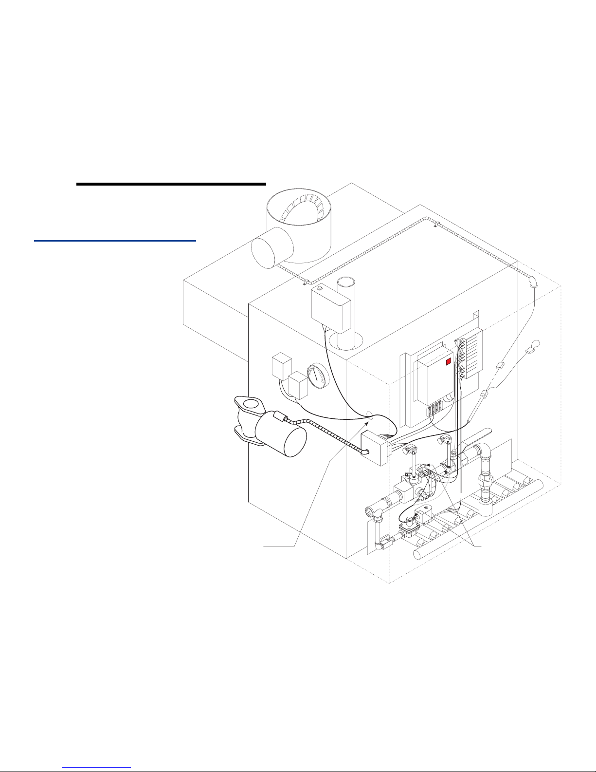
Figure 6
Control assembly — water boiler
(CSD-1 is not availabe for water
boilers with tankless heaters.)
Wiring — water boilersVI
Page 13
Part Number 550-110-677/0299
13
CSD-1 control system — Natural gas
EGH-105 to EGH-125 EGH-105 to EGH-125
EGH-105 to EGH-125 EGH-105 to EGH-125
EGH-105 to EGH-125 Control Supplement
1 CSD-1 control panel 14 Pilot shutoff valve
2 Ignition control 15 Leak test valves with plugs
3
Impulse relay and lighted push-button alarm
silencing switch
16 Gas supply connection
17 Burner manifold
5 Transformer/relay 18 Limit control, auto reset
6 Junction box 19 Limit control, manual reset
7 Damper (optional) 20 Pressure/temperature gauge
8 Damper connector 21 Wire harness
9 Dummy plug 22 Pilot spark & sense wires
10 Damper harness 23 Pilot gas tubing
11 Main gas valve 24 Circulator, by others
12 Manual gas valve
25
Probe LWCO, Manual reset (Mount in supply or return piping above top of boiler
between boiler and any isolation valve(s).)
13 Pilot gas valve
13a Pilot gas pressure regulator
Page 14
Part Number 550-110-677/0299
14
o
NOTES:
TO COMPONENT MANUFACTURER’S INSTRUCTIONS FOR APPLICATION WIRING AND
FOR MULTIPLE ZONE SYSTEMS USING ZONE VALVES OR CIRCULATORS, REFER
5. THERMOSTAT - FOR SINGLE ZONE SYSTEMS, THERMOSTAT ANTICIPATOR SETTING IS 0.40 AMPS.
4. REFER TO CONTROL COMPONENT INSTRUCTIONS PACKED WITH BOILER FOR APPLICATION
3. IF ORIGINAL WIRE AS SUPPLIED WITH THE APLIANCE MUST BE REPLACED,
8. PILOT LEADWIRES ARE NOT FIELD REPLACEABLE. REPLACE
7. DENOTES FIELD INSTALLED CHASSIS GROUND.
9. OPERATING CONTROL REQUIRED WITH TANKLESS HEATER.
INSTALLATION/OPERATING MANUAL.
EMCS - FOR EMCS CONNECTION IN PLACE OF THERMOSTAT, REFER TO EMCS
THERMOSTAT ANTICIPATOR SETTING.
TYPE 105 C OR IT’S EQUIVALENT MUST BE USED.
NATIONAL, PROVINCIAL OR LOCAL CODE REQUIREMENTS.
B. CANADA - C.S.A. C22.1 CANADIAN ELECTRICAL CODE PART 1 AND ANY OTHER
A. U.S.A. - NATIONAL ELECTRICAL CODE AND ANY OTHER NATIONAL, STATE OR LOCAL
1. ALL WIRING MUST BE INSTALLED IN ACCORDANCE WITH:
ELECTRICAL SHOCK HAZARD, CAN CAUSE SEVERE
INJURY OR DEATH. DISCONNECT POWER
BEFORE INSTALLING AND/OR SERVICING.
2. ALL CONTACTS SHOWN WITHOUT POWER APPLIED-OFF SHELF CONDITION.
CODE REQUIREMENTS.
INFORMATION.
6. L.W.C.O., PRESSURE CONTROLS, WIRED IN SERIES.
10. ALARM CONTACT RATINGS: 15 AMP @ 250 VAC.
PILOT ASSEMBLY IF NECESSARY.
IGNITION CONTROL PANEL TERMINAL.
TRANSFORMER TERMINAL.
IGNITION CONTROL MODULE TERMINAL.
IGNITION CONTROL PANEL LAMP
HIGH VOLTAGE FIELD
LOW VOLTAGE FACTORY
R
HIGH VOLTAGE FACTOR Y
IGNITION CABLE
LOW VOL TAGE FIELD
SPARK
24V (G)
SENSE
2
SENSOR
IGNITOR
R
2K
MV/PV
PV
MV
1
1
A
ALARM
24V
ALARM
2K1
GAS VAL VE
ROBERTSHAW
D
D
TR
TH
2K2
2K3
N/A
SEE NOTE 10
2K4
2
A
VALVE
PILOT
TRANSFORMER
FUSE
DAMPER
TO
22
11
66
44
535
3
THERMOSTAT
CABLE
1K1
MANUAL RESET
PROBE LWCO
RELAY COIL
1K
LADDER WIRING DIAGRAM
SWITCH
120 V.A.C.
SERVICE
SOLENOID
Y
G
R
EQUIPMENT
(NOTE 7)
GROUND
PRESSURETROL PRESSURETROL
MANUAL RESET
OPERATING CONTROL
FLOAT LWCO
C
550-225-027/0199
Figure 7
Water boiler wiring —
ladder and schematic diagrams
Wiring — steam
gravity return
VI
Page 15
Part Number 550-110-677/0299
15
CSD-1 control system — Natural gas
EGH-105 to EGH-125 EGH-105 to EGH-125
EGH-105 to EGH-125 EGH-105 to EGH-125
EGH-105 to EGH-125 Control Supplement
NOTE 10
TERMINAL
BLOCK
1
2
A1A
2
W
JUNCTION BOX
EQUIPMENT
GROUND
(BY OTHERS)
(NOTE 7)
N
H
SWITCH
SERVICE
C
WIRE NUTS (2)
W
BK
G
Y
G
BK
BK
DAMPER
TO
BK
R
TRANSFORMER
120/24 V.A.C .
RELAY
DPST
PLUG-IN
CABLE
G
(NOTE 5)
THERMOSTAT
OR EMCS
PROBE LWCO
W
BK
G
BK
CONNECTOR
DAMPER
Y
GAS VALVE
ROBERTSHAW
D
D
TH
TR
BK
W
MANUAL RESET
O
W
R
(NOTE 8)
PILOT
PRESSURETROL
MANUAL RESET
PRESSURETROL
UNIVERSAL SPARK
IGNITION CONTROL
SENSE
SPARK
MV
MV/PV
PV
ALARM
ALARM
24V
24V (GND)
BK
PILOT
SOLENOID
R
W
R
MOMENTARY
SWITCH
R
Y
IMPULSE
RELAY
R
G
Y
R
Y
R
R
R
G
R
R
R
G
G
R
W
PRE-WIRED PANEL
SCHEMA TIC WIRING DIAGRAM
BK
BK
(NOTE 6)
G
Y Y
FLOAT LWCO
(NOTE 9)
CONTROL
OPERATING
BK
G
VALVE
Page 16
Part Number 550-110-677/0299
16
MV
MV/PV
PV
ALARM
ALARM
24 V
24 V (GND)
SENSE
SPARK
MV
MV/PV
PV
ALARM
ALARM
24 V
24 V (GND)
SENSE
SPARK
677-01
1
2
3
4
5
6
10
8
9
11
12
14
15
15
16
17
18
19
20
21
22
23
24
25
25
26
27
Install strain relief bushings
wherever electrical wiring
passes through jacket.
7
Vent connections — Connect
with ¼" tubing and run vent
line outside building per code
requirements.
13
13a
Figure 8
Control assembly — steam, gravity return
Wiring — steam
gravity return
VI
When using a tankless heater,
knockout the opening in the
inner panel. Locate the controls
to allow room for the tankless
heater piping. The tankless
heater temperature control (not
shown) installs in the heater
tapping.
Page 17
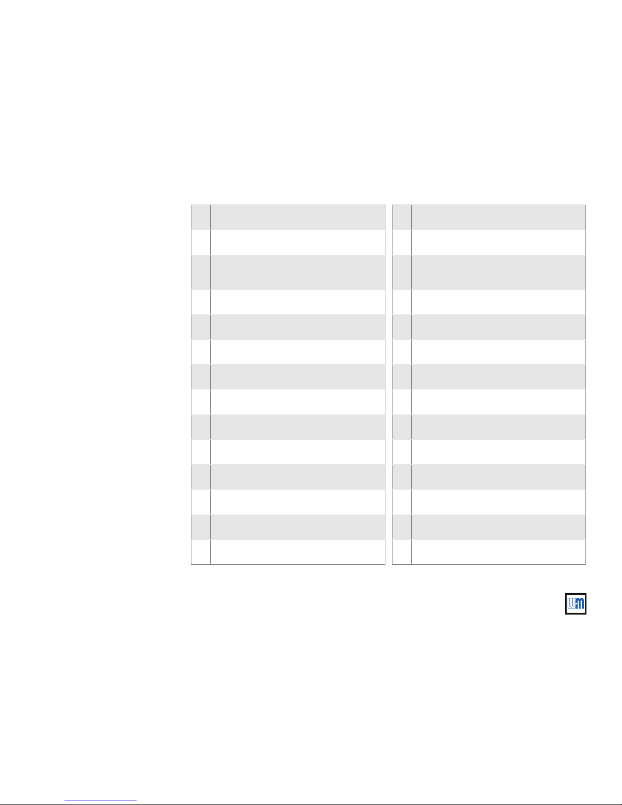
Part Number 550-110-677/0299
17
CSD-1 control system — Natural gas
EGH-105 to EGH-125 EGH-105 to EGH-125
EGH-105 to EGH-125 EGH-105 to EGH-125
EGH-105 to EGH-125 Control Supplement
1 CSD-1 control panel 14 Pilot shutoff valve
2 Ignition control 15 Leak test valves with plugs
3
Impulse relay and lighted push-button alarm
silencing switch
16 Gas supply connection
4 Terminal strip 17 Burner manifold
5 Transformer/relay 18 Limit control, automatic reset
6 Junction box 19 Limit control, manual reset
7 Damper (optional) 20 Pressure gauge
8 Damper connector 21 Siphons
9 Dummy plug 22 Gauge glass & valves
10 Damper harness 23 Probe LWCO, manual reset
11 Main gas valve 24 Float LWCO control, automatic reset
12 Manual gas valve 25 Wire harness
13 Pilot gas valve 26 Pilot spark & sense wires
13a Pilot gas pressure regulator 27 Pilot gas tubing
Page 18
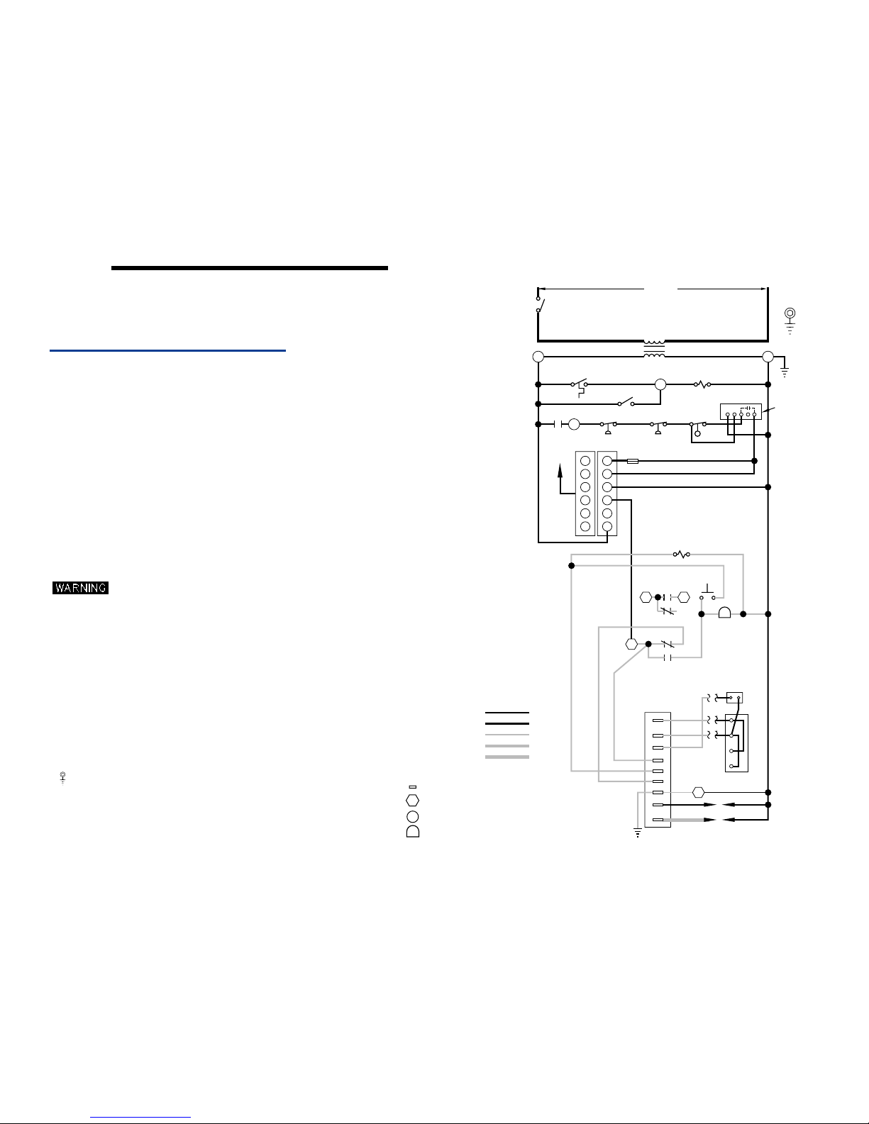
Part Number 550-110-677/0299
18
o
NOTES:
TO COMPONENT MANUFACTURER’S INSTRUCTIONS FOR APPLICATION WIRING AND
FOR MULTIPLE ZONE SYSTEMS USING ZONE VALVES OR CIRCULATORS, REFER
5. THERMOSTAT - FOR SINGLE ZONE SYSTEMS, THERMOSTAT ANTICIPATOR SETTING IS 0.40 AMPS.
4. REFER TO CONTROL COMPONENT INSTRUCTIONS PACKED WITH BOILER FOR APPLICATION
3. IF ORIGINAL WIRE AS SUPPLIED WITH THE APPLIANCE MUST BE REPLACED,
8. PILOT LEADWIRES ARE NOT FIELD REPLACEABLE. REPLACE
7. DENOTES FIELD INSTALLED CHASSIS GROUND.
9. OPERATING CONTROL REQUIRED WITH TANKLESS HEATER.
INSTALLATION/OPERATING MANUAL.
EMCS - FOR EMCS CONNECTION IN PLACE OF THERMOSTAT, REFER TO EMCS
THERMOSTAT ANTICIPATOR SETTING.
TYPE 150 C OR IT’S EQUIVALENT MUST BE USED.
NATIONAL, PROVINCIAL OR LOCAL CODE REQUIREMENTS.
B. CANADA - C.S.A. C22.1 CANADIAN ELECTRICAL CODE PART 1 AND ANY OTHER
A. U.S.A. - NATIONAL ELECTRICAL CODE AND ANY OTHER NATIONAL, STATE OR LOCAL
1. ALL WIRING MUST BE INSTALLED IN ACCORDANCE WITH:
ELECTRICAL SHOCK HAZARD, CAN CAUSE SEVERE
INJURY OR DEATH. DISCONNECT POWER
BEFORE INSTALLING AND/OR SERVICING.
2. ALL CONTACTS SHOWN WITHOUT POWER APPLIED-OFF SHELF CONDITION.
CODE REQUIREMENTS.
INFORMATION.
6. L.W.C.O., PRESSURE CONTROLS, WIRED IN SERIES.
10. ALARM CONTACT RATINGS: 15 AMP @ 250 VAC.
PILOT ASSEMBLY IF NECESSARY.
11. REMOVE JUMPER BAR BETWEEN TERMINAL "H" AND TERMINAL "C".
IGNITION CONTROL PANEL TERMINAL.
TRANSFORMER TERMINAL.
IGNITION CONTROL MODULE TERMINAL.
IGNITION CONTROL PANEL LAMP
HIGH VOLTAGE FIELD
LOW VOLTAGE FACTORY
R
HIGH VOLTAGE FACTOR Y
IGNITION CABLE
LOW VOL TAGE FIELD
SPARK
24V (G)
SENSE
2
SENSOR
IGNITOR
R
2K
MV/PV
PV
MV
1
1
A
ALARM
24V
ALARM
2K1
GAS VAL VE
ROBERTSHAW
D
D
TR
TH
2K2
2K3
N/A
SEE NOTE 10
2K4
2
A
VALVE
PILOT
TRANSFORMER
FUSE
DAMPER
TO
22
11
66
44
535
3
THERMOSTAT
CABLE
1K1
MANUAL RESET
PROBE LWCO
RELAY COIL
1K
LADDER WIRING DIAGRAM
SWITCH
120 V.A.C.
SERVICE
SOLENOID
Y
G
R
EQUIPMENT
(NOTE 7)
GROUND
PRESSURETROL
PRESSURETROL
MANUAL RESET
OPERATING CONTROL
& PUMP
CONTROL
NHCWB
(NOTE 11)
FLOAT LWCO
C
550-225-028/0399
Figure 9
Water boiler wiring —
ladder and schematic diagrams
Wiring — steam
pumped return
VI
Page 19
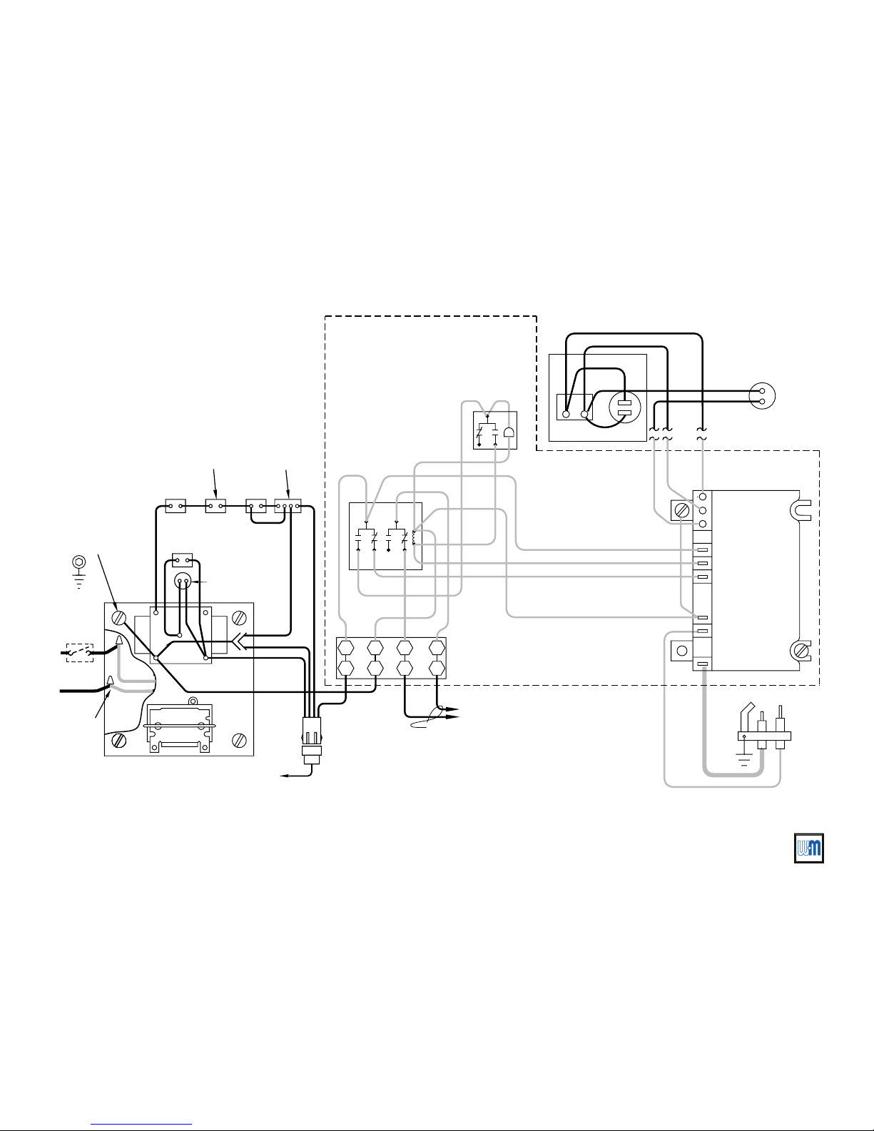
Part Number 550-110-677/0299
19
CSD-1 control system — Natural gas
EGH-105 to EGH-125 EGH-105 to EGH-125
EGH-105 to EGH-125 EGH-105 to EGH-125
EGH-105 to EGH-125 Control Supplement
NOTE 10
TERMINAL
BLOCK
1
2
A1A
2
W
JUNCTION BOX
EQUIPMENT
GROUND
(BY OTHERS)
(NOTE 7)
N
H
SWITCH
SERVICE
C
W
BK
G
Y
G
BK
BK
DAMPER
TO
BK
R
TRANSFORMER
120/24 V.A.C .
RELAY
DPST
PLUG-IN
CABLE
G
(NOTE 5)
THERMOSTAT
OR EMCS
PROBE LWCO
W
BK
G
BK
CONNECTOR
DAMPER
Y
GAS VALVE
ROBERTSHAW
D
D
TH
TR
BK
W
MANUAL RESET
O
W
R
(NOTE 8)
PILOT
PRESSURETROL
MANUAL RESET
PRESSURETROL
UNIVERSAL SPARK
IGNITION CONTROL
SENSE
SPARK
MV
MV/PV
PV
ALARM
ALARM
24V
24V (GND)
BK
PILOT
SOLENOID
R
W
R
MOMENTARY
SWITCH
R
Y
IMPULSE
RELAY
R
G
Y
R
Y
R
R
R
G
R
R
R
G
G
R
W
PRE-WIRED PANEL
SCHEMA TIC WIRING DIAGRAM
BK
BK
(NOTE 6)
G
Y Y
CONTROL
& PUMP
BK
CONTROL
(NOTE 9)
OPERATING
G
FLOAT LWCO
VALVE
WIRE NUTS (2)
Page 20
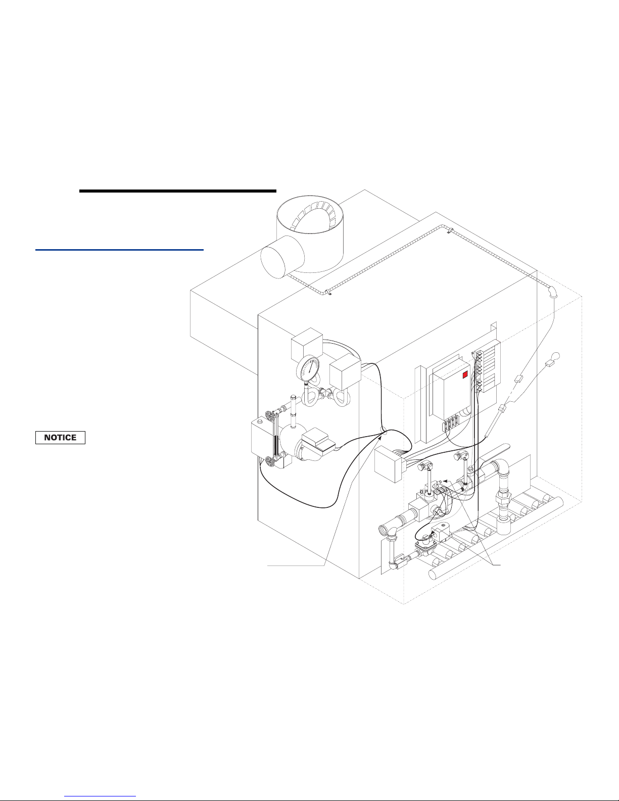
Part Number 550-110-677/0299
20
MV
MV/PV
PV
ALARM
ALARM
24 V
24 V (GND)
SENSE
SPARK
677-01-p
1
2
3
4
5
6
7
10
8
9
11
12
14
15
15
16
17
18
19
20
21
22
25
25
26
27
23
24
Install strain relief bushings
wherever electrical wiring
passes through jacket.
Vent connections — Connect
with ¼" tubing and run vent
line outside building per code
requirements.
13
13a
Figure 10
Control assembly — steam, pumped return
Wiring — steam
pumped return
VI
When using a tankless heater,
knockout the opening in the
inner panel. Locate the controls
to allow room for the tankless
heater piping. The tankless
heater temperature control (not
shown) installs in the heater
tapping.
Page 21
Part Number 550-110-677/0299
21
CSD-1 control system — Natural gas
EGH-105 to EGH-125 EGH-105 to EGH-125
EGH-105 to EGH-125 EGH-105 to EGH-125
EGH-105 to EGH-125 Control Supplement
1 CSD-1 control panel 14 Pilot shutoff valve
2 Ignition control 15 Leak test valves with plugs
3
Impulse relay and lighted push-button alarm
silencing switch
16 Gas supply connection
4 Terminal strip 17 Burner manifold
5 Transformer/relay 18 Limit control, auto reset
6 Junction box 19 Limit control, manual reset
7 Damper (optional) 20 Pressure gauge
8 Damper connector 21 Siphons
9 Dummy plug 22 Gauge glass & valves
10 Damper harness 23 Probe LWCO, manual reset
11 Main gas valve 24 Float LWCO/pump control, auto reset
12 Manual gas valve 25 Wire harness
13 Pilot gas valve 26 Pilot spark & sense wires
13a Pilot gas pressure regulator 27 Pilot gas tubing
Page 22

EGH-105 to EGH-125 EGH-105 to EGH-125
EGH-105 to EGH-125 Control Supplement
EGH-105 to EGH-125 EGH-105 to EGH-125
Final adjustmentsVII
Before proceeding:
To place boiler in operation:
1. Follow EGH Manual instructions for Final Adjustments, Section VII,
including filling the boiler and skimming steam boilers.
Skimming the boiler as described in Section VII of the
EGH Manual requires firing the boiler. Always follow
boiler Operating instructions, Figure 11, when starting
the boiler. Failure to do so could result in severe personal
injury, death or substantial property damage.
2. Inspect base insulation as instructed in Section VII of the EGH Manual.
1. Follow Operating instructions, Figure 11, to start boiler.
2. If boiler starts correctly, proceed with Check-out procedure, Section
VIII of this Supplement.
3. If boiler fails to start, check:
❏ Loose connection or blown fuse?
❏ Limit setting below boiler water temperature or steam pressure?
❏ Thermostat below room temperature?
❏ Manual reset device needs to be reset?
❏ Gas not turned on at meter and boiler?
❏ Incoming natural gas pressure less than 5" W. C.?
4. If above fails to eliminate the trouble, refer to Check-out procedure
— troubleshooting
in this Supplement, Section VIII.
22
Part Number 550-110-677/0299
Page 23
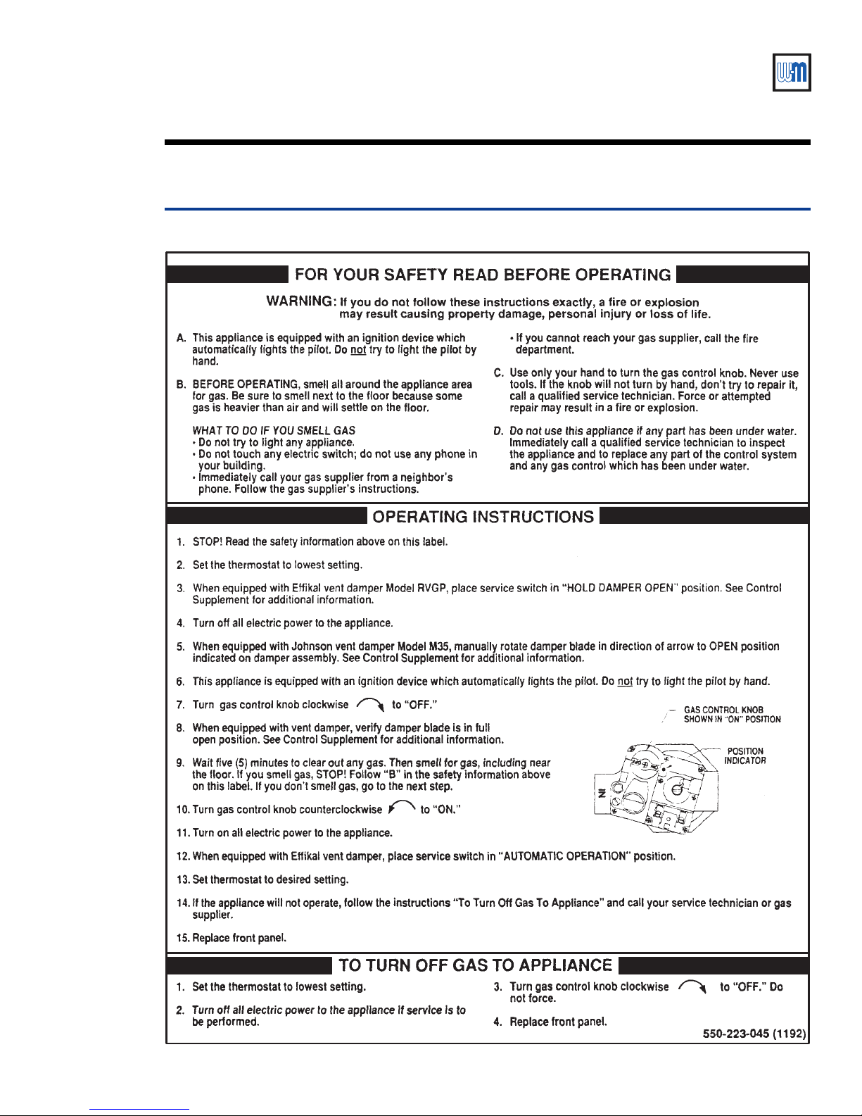
CSD-1 control system — Natural gas
VII
Final adjustments —
Figure 11 Operating instructions
operating instructions
Part Number 550-110-677/0299
23
Page 24
EGH-105 to EGH-125 EGH-105 to EGH-125
EGH-105 to EGH-125 Control Supplement
EGH-105 to EGH-125 EGH-105 to EGH-125
Check-out procedure — operationVIII
Always follow boiler Operating instructions, Figure 11, when starting the
boiler. Failure to do so could result in severe personal injury, death or substantial
property damage.
1. Increase setting of room thermostat (or operating control) to call for heat.
2. Vent damper (if provided) will slowly open. When damper is fully open, the ignition
control will open pilot gas valve and start spark.
Vent damper must be in open position when appliance main burners are
operating. If damper is not in open position, flue products will spill into the
building, causing severe personal injury or death.
3. If pilot lights and proves within 15 seconds, the ignition control turns off the spark and
opens the main gas valve (dual valves in single body). Main burners ignite.
If pilot does not light and prove within 15 seconds, the ignition control shuts
off pilot gas and spark and waits 5 minutes. It then will retry. If the second
ignition attempt fails, the ignition control will lockout and close the alarm
contact of the impulse relay.
4. During main burner operation:
• The ignition control monitors pilot flame current. If signal is lost, main valve is closed,
spark is activated, and the operating sequence returns to step 3.
• If power is interrupted, the control system shuts off pilot and main gas valves and
restarts at Step 1 when power is restored.
5. Stop the call for heat (lower thermostat or operating control).
• Pilot and main gas valves will close.
• Damper (if provided) will close.
6. Boiler is now in the off cycle.
7. Repeat steps 1 through 6 several times to verify operation.
8. Return thermostat or operating control to normal setting.
24
Part Number 550-110-677/0299
Page 25
CSD-1 control system — Natural gas
Check-out procedure — leak testVIII
For your safety, turn off electrical
power supply before making any
electrical connections to avoid
possible shock hazard.
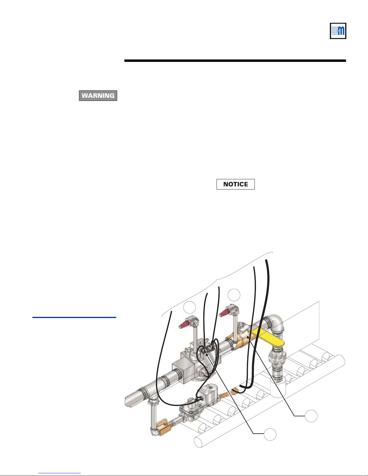
1. Turn off power to the boiler and remove the (RED)
wire from terminal TH of the main gas valve
(Figure 12, item 1). Tape off terminal end of
removed wire and restore power to the boiler.
2. Close manual gas valve (Figure 12, item 2).
3. Check that both leak test valves (Figure 12, items 3
and 4) are closed. Then remove plugs and insert
1/8" NPT hose barb fittings as shown in Figure 12.
4. Attach a U-tube manometer to first leak test valve
(Figure 12, item 3).
5. Open first leak test valve (Figure 12, item 3) and
check for pressure. See NOTICE at right.
6. Close first leak test valve (Figure 12, item 3) and
remove manometer.
7. Attach manometer to second leak test valve (Figure
12, item 4 ).
8. Apply call for heat to boiler and check that
electronic pilot proves.
9. Open second leak test valve (Figure 12, item 4) and
check for pressure. See NOTICE below.
10. Close second leak test valve and remove
manometer.
11. Remove call for heat to boiler. Turn off power to
the boiler.
12. Remove hose barbs from leak test valves and
replace plugs.
13. Replace (RED) wire to terminal TH of gas valve.
14. Open manual gas valve (Figure 12, item 2) and
restore power to boiler.
When checking for pressure at the
leak test valves, it is normal to find a
small pressure reading. If the
pressure continues to rise after
opening the leak test valve, the main
valve seat is leaking and should be
replaced.
Figure 12
Leak test procedure
To control panel
4
3
2
1
677-11
Part Number 550-110-677/0299
25
Page 26
EGH-105 to EGH-125 EGH-105 to EGH-125
EGH-105 to EGH-125 Control Supplement
EGH-105 to EGH-125 EGH-105 to EGH-125
VIII
Check-out procedure — troubleshooting
Verify proper operation after servicing
Never jumper (bypass) any device except for momentary
testing as outlined in Troubleshooting Charts. Substantial
property damage and/or severe personal injury could
occur.
Burner access panel must be in position during boiler
operation to prevent momentary flame rollout on
ignition of main flame. Severe personal injury or
substantial property damage will result.
Label all wires prior to disconnection when servicing
controls. Wiring errors can cause improper and
dangerous operation.
Before troubleshooting:
a. Have a voltmeter that can check 120VAC, 24VAC, a microammeter
with minimum scale range of 0–25, and continuity tester.
b. Check for 120VAC (minimum 102 – maximum 132) to boiler.
c. Check for 24VAC at secondary side of transformer.
d. Make sure thermostat is calling for heat and contacts (including
appropriate zone controls) are closed. Check for 24VAC between
thermostat wire nuts and ground.
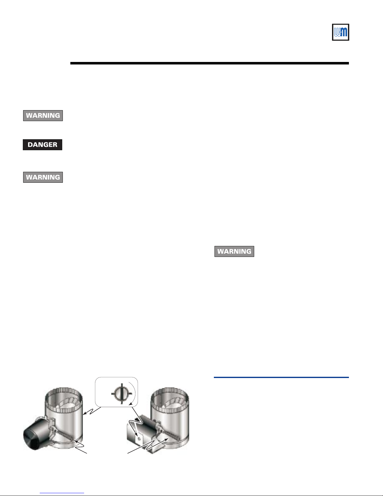
In event of actuator failure:
Effikal damper:
If troubleshooting chart recommends replacing actuator and actuator is
not immediately available, damper blade can be fixed in an open position
to allow boiler operation. Manually turning blade can cause actuator
damage. Follow these instructions only in case of no heat or damper
actuator malfunction. See Figure 13.
1. Move damper service switch to "HOLD DAMPER OPEN" position.
Apply call for heat to boiler. Damper blade should then rotate to open
position and boiler will fire.
2. If Step 1 does not open damper, manually rotate
damper blade to open position using wrench or
pliers on flat shaft between damper and actuator
(Figure 13). Boiler will fire.
Verify that damper service switch is in "HOLD
DAMPER OPEN
3. Do not leave damper permanently in this position.
Replace actuator immediately. If damper is left in
open position, boiler will not operate at published
efficiencies.
See damper manufacturer's instructions packed
with damper for additional information.
Johnson damper:
If troubleshooting chart recommends replacing
actuator and actuator is not immediately available,
damper blade can be fixed in an open position to allow
boiler operation. Follow these instructions only in case
of no heat or damper actuator malfunction.
See Figure 13.
1. Turn off power to boiler.
2. Refer to damper manufacturer’s instructions for
procedure to fix damper in open position.
3. Turn on power to boiler.
4. Using wrench or pliers on flat shaft section,
manually rotate damper blade until green light
turns on. Boiler will fire.
5. Do not leave damper permanently in this position.
Replace actuator immediately. If damper is left in
open position, boiler will not operate at published
efficiencies.
See damper manufacturer's instructions packed
with damper for additional information.
" position.
Failure to turn off power to boiler
can result in severe personal injury,
death or substantial property
damage.
Open
Closed
Damper blade
indicator
Wrench or pliers
Effikal damper
26
Johnson Controls damper
677-14
Figure 13
T emporary manual opening of vent damper —
refer also to vent damper manuf acturer’s
instructions.
Part Number 550-110-677/0299
Page 27
CSD-1 control system — Natural gas
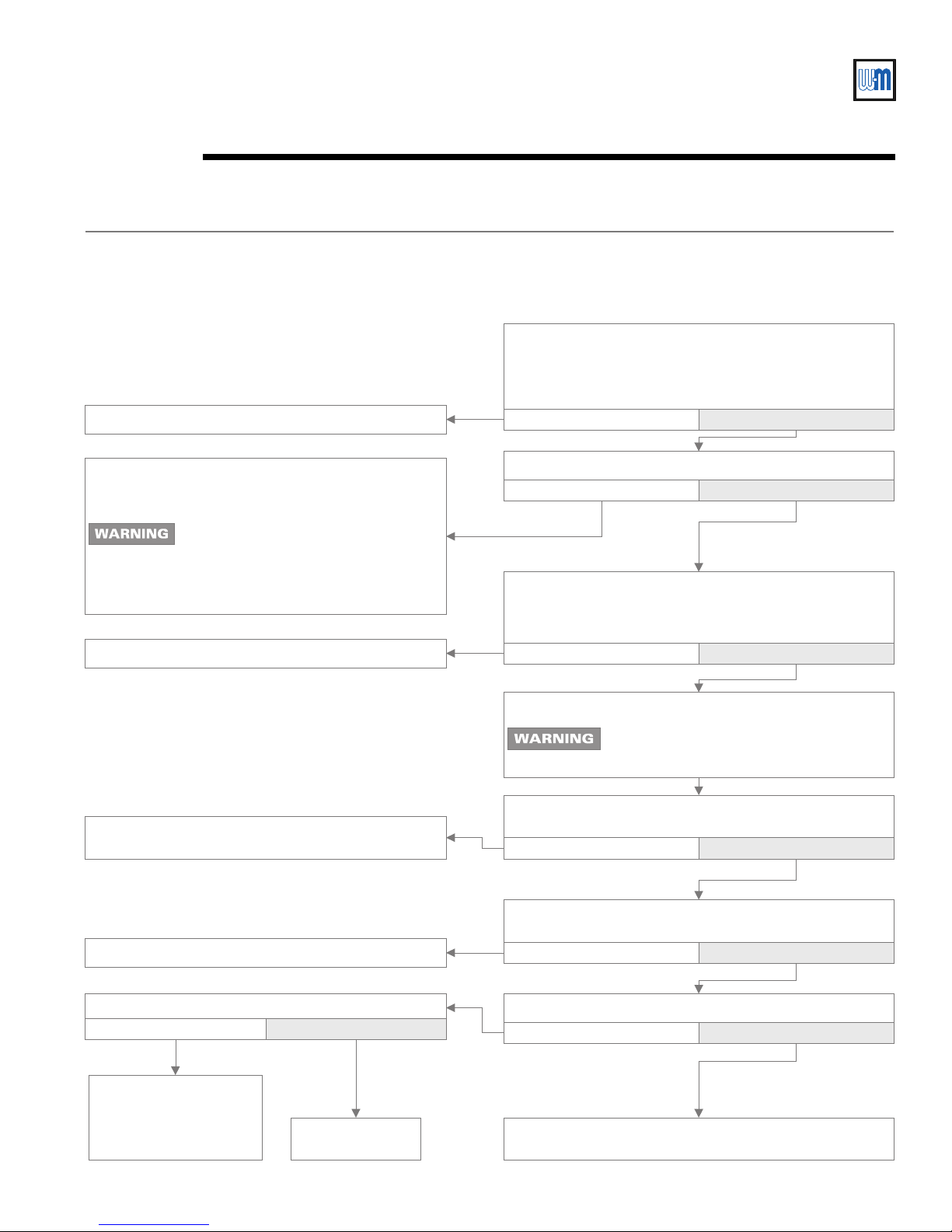
Check-out procedure — troubleshootingVIII
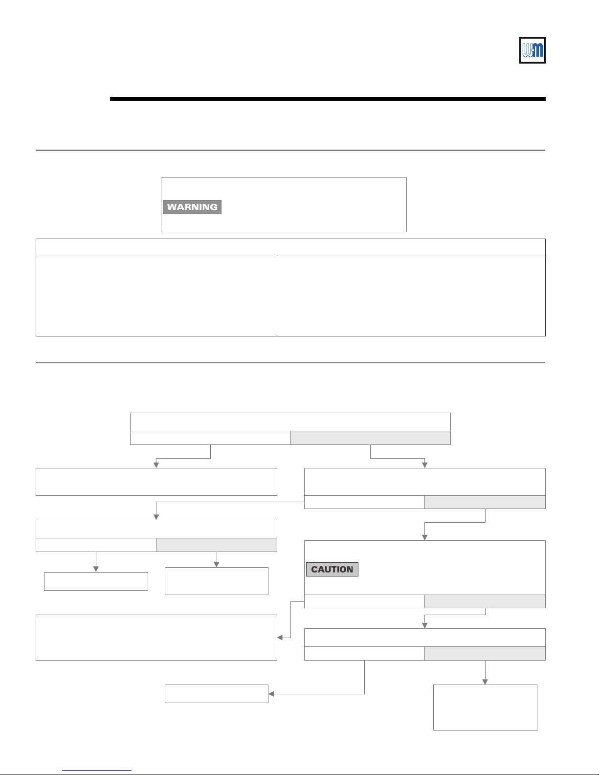
TS-1: No Spark — System (boiler without vent damper) does not work
VISUALLY CHECK — Is ground wire connected from
GND (Burner) to ignition control mounting screw, and
ground wire connected from transformer terminal C to case
ground?
Correct by making connections.
Check for open thermostat, circulator relay, operating
control, limit control or LWCO. Check the CSD-1
control panel, impulse relay and push-button switch.
If limit controls or water level controls
lockout on manual reset, determine
cause and correct condition. Failure to
do so could result in severe personal
injury, death or substantial property
damage.
Replace ignition control. Retest.
Securely connect spark wire.Then turn ON supply
voltage.Retest.
No Yes
Is 24VAC present across terminals 24V and 24V(GND)?
No Yes
Open thermostat (or operating control) contacts for 15
seconds.Close thermostat contacts.Is 24VAC across
terminals PV & MV/PV?
No Yes
Turn OFF supply voltage.
Electrical shock hazard. Failure to turn off
power before proceeding could cause
severe personal injury or death.
Check spark wire.Is it securely connected to spark
transformer?
No Yes
Replace pilot assembly.Retest.
Is spark gap 0.125" and isolated in pilot gas stream?
No Yes
Replace pilot assembly,
turn ON supply voltage.
Operate system several
complete heat cycles.
Part Number 550-110-677/0299
Replace ignition
control. Retest.
Is condition of spark wire good (not cut, brittle, burned or
cracked)?
No Yes
Is spark electrode ceramic cracked?
No Yes
Replace pilot assembly, turn ON supply voltage, operate
system several complete heat cycles.
27
Page 28
EGH-105 to EGH-125 EGH-105 to EGH-125
EGH-105 to EGH-125 Control Supplement
EGH-105 to EGH-125 EGH-105 to EGH-125
Check-out procedure — troubleshootingVIII
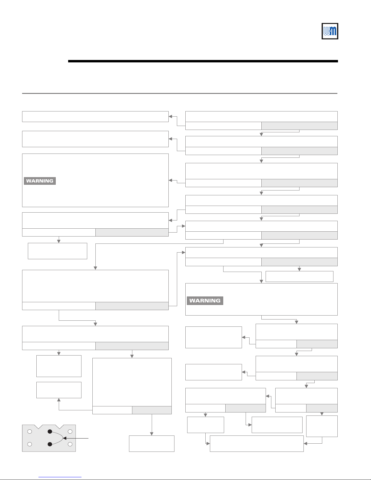
TS-2: No Spark — System (boiler with vent damper) does not work
Is damper harness securely plugged in at both ends?Secure connections.
No Yes
Check for loose wire connections or bad relay on
transformer.
Check for open thermostat, circulator relay, operating
control, limit control or LWCO. Check the CSD-1 control
panel, impulse relay and push-button switch.
If limit controls or water level controls
lockout on manual reset, determine cause
and correct condition. Failure to do so could
result in severe personal injury, death or
substantial property damage.
Check for out of round stack section.Does motor rotate
open?
No Yes
Is 24VAC present across transformer terminals C & Y?
No Yes
Is 24VAC present across terminal C and yellow wire on
damper connector?
No Yes
Is damper rotated open?
No
Is 24VAC present across terminals PV and MV/PV?
No Yes
Yes
Replace actuator.
Retest.
Open thermostat contacts for 30 seconds.Damper will
rotate to closed position. Close thermostat contacts.
Damper will rotate to open position. Is 24VAC present
across terminals PV and MV/PV?
No
Check continuity of each wire in wiring harness to
damper.Does continuity exist for each wire?
No
Replace damper
wiring harness.
Retest.
Replace ignition
control. Retest.
1
4
2
5
3
6
Remove damper harness from
boiler wiring harness.
TEMPORARILY install jumper
between terminal 2 and
terminal 5 on damper plug in
boiler wiring harness. See
figure below.Does boiler fire?
No Yes
Temporary
jumper
Yes
Yes
Replace damper
actuator.Retest.
Is spark present now?
No Yes
Turn OFF supply voltage.
Electrical shock hazard. Failure to turn off
power before proceeding could cause
severe personal injury or death.
Securely connect
and turn ON supply
voltage.Retest.
Replace pilot
assembly.Retest.
Is spark gap 0.125" and
located in pilot gas stream?
No Yes
Replace pilot
assembly.
Turn ON supply voltage and operate
system several complete cycles.
Retest.
Check spark wire.Is it securely
connected to ignition control?
No Yes
Is condition of spark wire good
(not brittle, burned or cracked)?
No Yes
Is spark electrode
ceramic cracked?
No Yes
Replace ignition
control. Retest.
Replace
pilot
assembly.
28
Part Number 550-110-677/0299
Page 29
CSD-1 control system — Natural gas
Check-out procedure — troubleshootingVIII
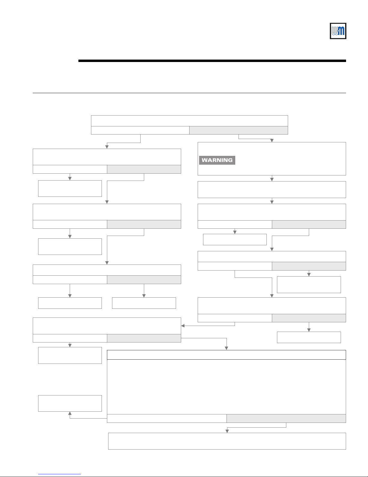
TS-3: Pilot lights — Main valve will not come on (boiler with or without damper)
Does spark stay on for more than a few seconds after pilot is established?
No Yes
Turn OFF supply voltage.
Is 24VAC between terminals MV and MV/PV on ignition
control?
No Yes
Electrical shock hazard. Failure to turn off
power before proceeding could cause
severe personal injury or death.
Replace ignition control.
Retest.
Is inlet gas pressure at least 5.0" W.C. and not over 14"
W.C.?
No Yes
Contact gas supplier to
correct.
Is main valve wiring secure at terminals?
No Yes
Correct wiring. Retest. Replace valve.Retest.
Check for continuity of sense wire and condition of
insulation.
NOT OK OK
Replace pilot assembly.
Retest.
Replace ignition control.
Retest.
Set up microammeter to measure output current in flame sensor circuit as follows.
a. Detach sense lead from ignition control. Attach negative lead from microammeter to sense
terminal on ignition control.
b. Attach positive lead to sense wire from pilot assembly.
c. Disconnect main valve lead from terminal MV on ignition control.
d. Energize the system.Spark should ignite the pilot. As soon as pilot is burning,
microammeter should read at least 0.5 microamp for U.T. # 1003-615.
e. Is flame current signal less than the minimum specified in d above?
No Yes
Make sure sense wire is not wrapped around any pipe or
accessories.
Is sense wire securely attached to sense terminal and pilot
assembly?
No Yes
Correct and retest.
Is sensing probe ceramic cracked?
No Yes
Replace pilot assembly.
Retest.
Is sense wire or sensing probe shorted out to metal
surface?
No Yes
Correct and retest.
Does system have proper flame signal?
Check for proper gas pressure, clean pilot assembly, tight mechanical and electrical
connections.Also check for proper system grounding per following page.
Part Number 550-110-677/0299
29
Page 30
EGH-105 to EGH-125 EGH-105 to EGH-125
EGH-105 to EGH-125 Control Supplement
EGH-105 to EGH-125 EGH-105 to EGH-125
Check-out procedure — troubleshootingVIII
TS-3: Pilot lights — Main valve will not come on -
Turn OFF supply voltage.
Electrical shock hazard. Failure to turn off
power before proceeding could cause
severe personal injury or death.
To check ignition system grounding (instruction for continuation of TS-3)
Pilot assembly and ignition control must share common
ground with main burner.Nuisance shutdowns are often
caused by poor or erratic ground.
❏ Check for good metal-to-metal contact between pilot
burner bracket and main burner and between main
burner and burner rest.
continued from previous page
❏ Check ground lead from GND (Burner) terminal on
ignition control to ignition control mounting screw and
from C on transformer to transformer case ground.
Make sure connections are clean and tight.If wire is
damaged or deteriorated, replace with No.18 gauge
moisture-resistant, thermoplastic insulated wire with
105 °C minimum rating.
TS-4: Spark is present - pilot will not light (boiler with or without damper)
Are pilot valve wiring connections CORRECT and securely fastened?
No Yes
Connect securely to terminal PV on ignition control and
terminal TR on main gas valve.
Is pilot shutoff valve open?
No Yes
Open pilot shutoff valve.
Make sure pilot shutoff valve is open, 24VAC is present to
pilot valve and pilot line is not kinked or obstructed.Check
for clean pilot orifice.If OK, replace pilot gas valve.
Contact gas supplier to
correct gas pressure.
Replace pilot assembly.
30
Is inlet gas pressure at least 5.0" W.C. and not over 14"
W.C.?
No Yes
Is gas present at pilot burner assembly?
Remove MV wire from ignition control. Use a
match taped to a long screwdriver or pilot
lighter rod and manually light pilot.
No Yes
Is spark gap 0.125" and located in pilot gas stream?
No Yes
Block any draft around
boiler.Check for clean
pilot orifice.
Part Number 550-110-677/0299
Page 31

CSD-1 control system — Natural gas
Service and maintenanceIX
Complete Installation and Service Certificate in EGH Manual, Section IX.
Follow EGH Manual, Section IX, for service and maintenance of boiler.
Part Number 550-110-677/0299
31
Page 32
EGH-105 to EGH-125 EGH-105 to EGH-125
EGH-105 to EGH-125 Control Supplement
EGH-105 to EGH-125 EGH-105 to EGH-125
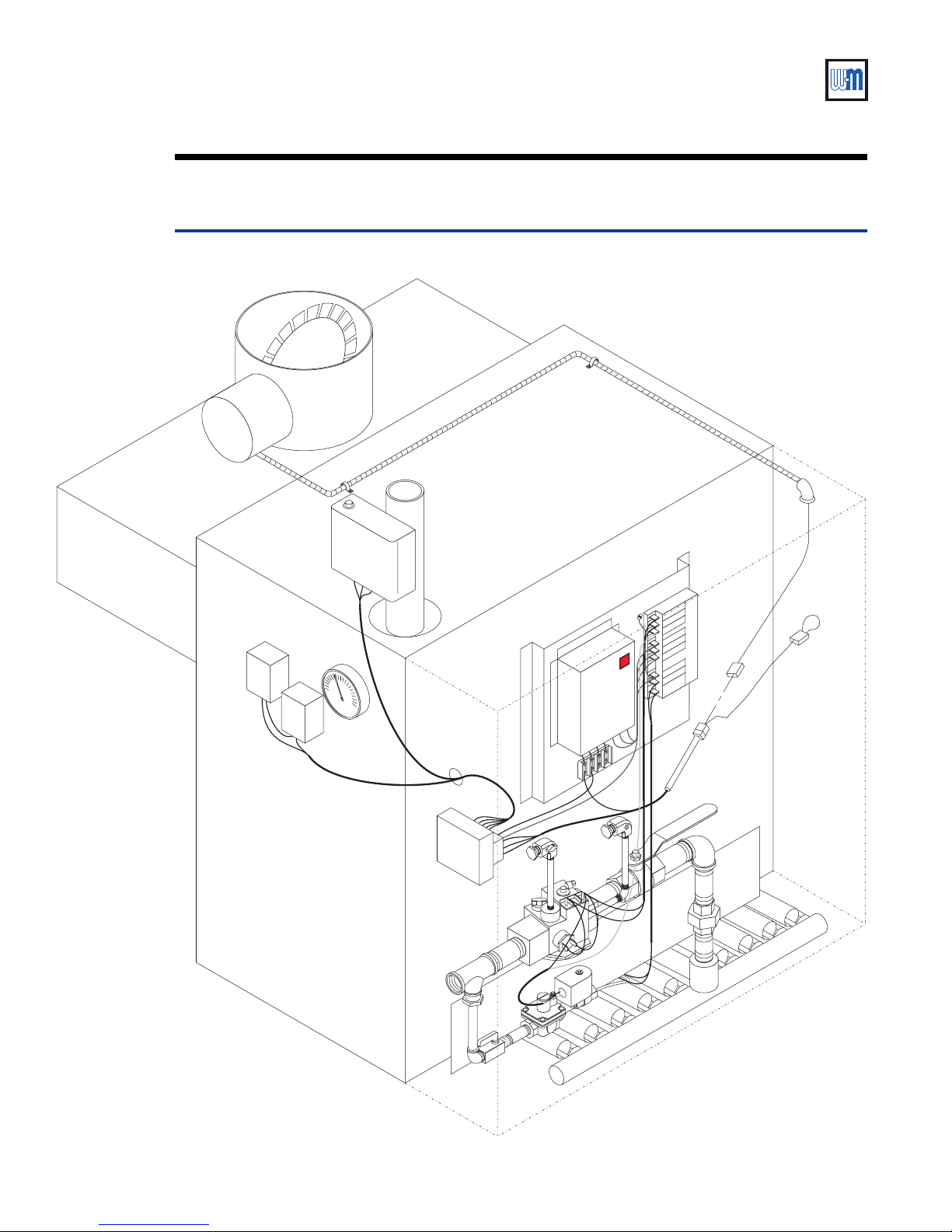
Replacement parts — water boilersX
Figure 14 Water boiler assembly
18
21
20
17
22
23
16
24
19
MV
MV
MV/PV
MV/PV
PV
PV
11
ALARM
ALARM
ALARM
13
14
15
ALARM
24 V
24 V
24 V (GND)
24 V (GND)
SENSE
SENSE
SPARK
SPARK
12
16
7
7
6
32
8a
9
5
8
10
2
1
677-12
Part Number 550-110-677/0299
Page 33
CSD-1 control system — Natural gas
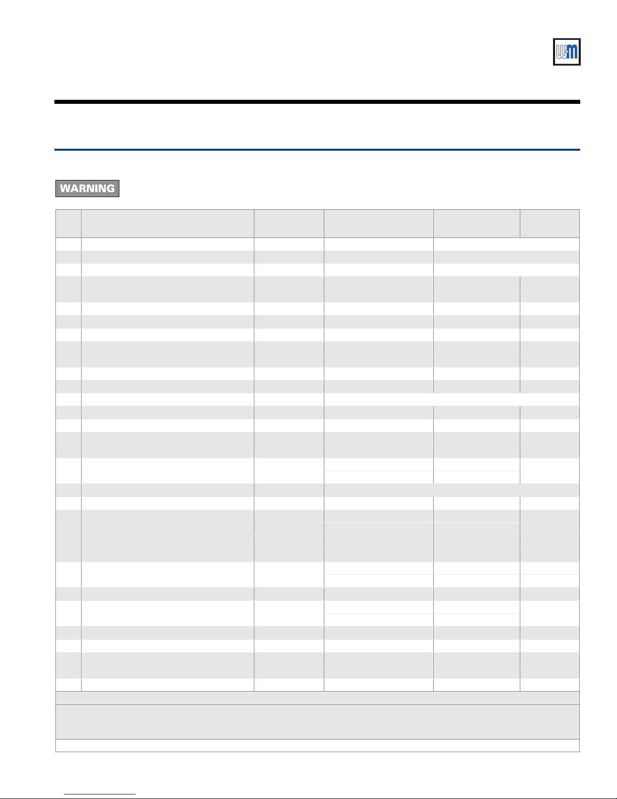
Table 5 Water boiler replacement parts
Before replacing any parts on the boiler — Turn off power to boiler and shut off gas supply.
Failure to comply could result in severe personal injury, death or substantial property damage.
Item Part description Boiler models Vendo r Vendor part number
1 Main burner EGH-105 – 125 Weil-McLain — See EGH Manual —
2 Main burner with pilot bracket EGH-105 – 125 Weil-McLain — See EGH Manual —
3 Pilot burner bracket (not shown) EGH-105 – 125 Weil-McLain — See EGH Manual —
4 Pilot burner (not shown) EGH-105 – 125
5 Main gas valve EGH-105 – 125 Robertshaw 7000DERHC-S7C 511-044-287
6 Manual gas valve, 1" NPT EGH-105 – 125 Watts FBV3-06 511-246-290
7 Leak test valve EGH-105 – 125 Key Gas 511-246-339
8 Pilot gas valve EGH-105 – 125
8a Pilot gas pressure regulator EGH-105 – 125 Maxitrol RV20VL 510-933-195
9 Pilot shutoff valve EGH-105 – 125 Conbraco 53-300-01 511-246-345
10 Pilot tubing, alum. 1/8" O.D. x 34" long EGH-105 – 125 Available at local supply house
11 Ignition control EGH-105 – 125 United Technologies 1003-615 511-330-086
12 Impulse relay EGH-105 – 125 Potter-Brumfield S89R-11ABD1-24 510-350-226
13 Push-button switch EGH-105 – 125
14 Lens cover EGH-105 – 125
15 Light bulb EGH-105 – 125 TI-¾ (available at local supply house)
16 Wiring harn ess, water boilers EGH-105 – 125 Weil-McLain 591-391-886
Vent damper assembly — optional
17
(not for use in Canada)
18 Vent damper actuator EGH-105 – 125
19 Vent damper harness EGH-105 – 125 Weil-McLain 10C321 591-391-795
20 Limit control, automatic reset EGH-105 – 125
21 Limit control, manual reset EGH-105 – 125 Honeywell L4006E-1000 510-312-041
22 Probe LWCO, manual reset EGH-105 – 125 McDonnell & Miller PS852M-24 511-114-530
23 Pressure/temperature gauge EGH-105 – 125
24 Transformer/relay EGH-105 – 125 Honeywell R8285D-5001 510-312-169
Note 1 — Johnson damper assembly consists of M35BC actuator and Y15 vent pipe.
Replacement parts must be purchased through a local Weil-McLain distributor. When ordering, specify boiler model and series and
include description and number of replacement par t. Results from using modi fied or other manufactured parts wil l not be covered
by warranty and may damage boiler or impair operation.
Refer to boiler manual for parts not listed above.
EGH-105
EGH-115 – 125
Beckett Gas E48A-1
Johnson Controls Q90GE-1
Honeywell V8046C-1014
Johnson Controls H91ABG
Honeywell AML21CBA2AA
Eaton Controls 221K11810
Honeywell AML51-C10R
Eaton Controls 220PM02A
Effikal RVGP-KS-10BF
Johnson Controls Q35GP-2 (note 1)
Effikal RVGP-KS-12BF
Johnson Controls Q35GR-2 (note 1)
Effikal only RVGP 510-512-337
Johnson only M35BE-1C 510-312-255
Honeywell L4080B-1311
White-Rodgers 11B83-16
Ametek 19998
ENFM-USA 4104-2-1/2-1/4CBM
Weil-McLain
part number
511-330-166
511-044-039
511-624-580
511-624-581
381-800-446
381-800-447
510-312-209
510-218-097
Part Number 550-110-677/0299
33
Page 34
EGH-105 to EGH-125 EGH-105 to EGH-125
EGH-105 to EGH-125 Control Supplement
EGH-105 to EGH-125 EGH-105 to EGH-125
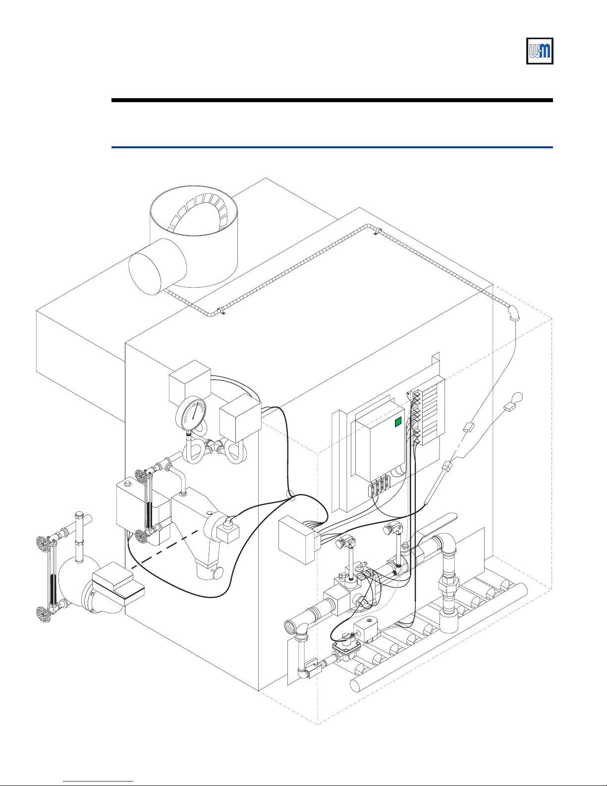
Replacement parts — steam boilersX
Figure 15 Steam boiler assembly
23b
22
18
24
21
23a
17
20
16
25
19
MV
MV
MV/PV
MV/PV
PV
PV
11
ALARM
ALARM
ALARM
13
14
15
ALARM
24 V
24 V
24 V (GND)
24 V (GND)
SENSE
SENSE
SPARK
SPARK
12
16
7
7
6
5
1
34
8a
9
8
10
2
677-13
Part Number 550-110-677/0299
Page 35
CSD-1 control system — Natural gas
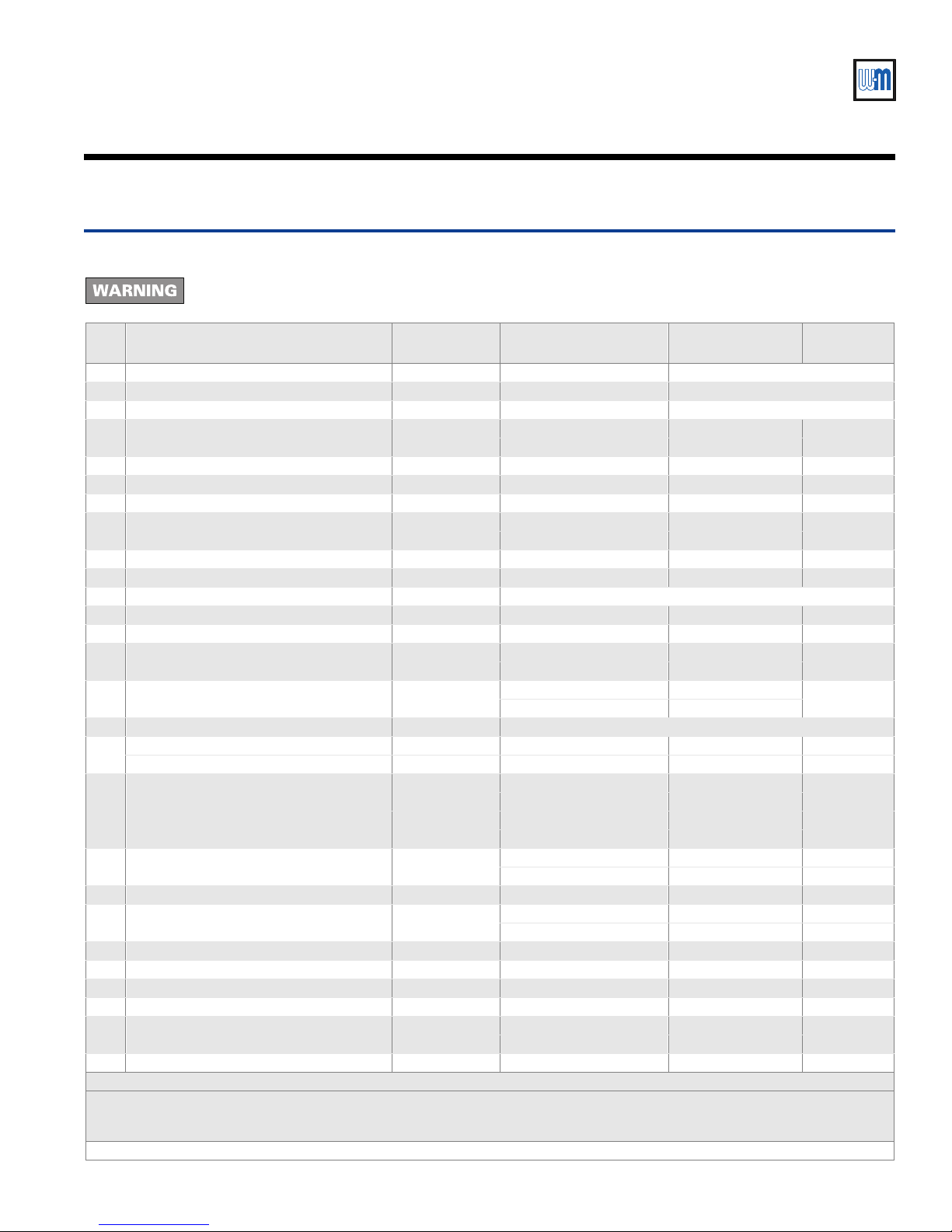
Table 6 Steam boiler replacement parts
Before replacing any parts on the boiler — Turn off power to boiler and shut off gas supply. Failure to comply could
result in severe personal injury, death or substantial property damage.
Item Part description Boiler models Vendor Vendor part number
1 Main burner EGH-105 – 125 Weil-McLain — See EGH Manual —
2 Main burner with pilot bracket EGH-105 – 125 Weil-McLain — See EGH Manual —
3 Pilot burner bracket (not shown) EGH-105 – 125 Weil-McLain — See EGH Manual —
4 Pilot burner (not shown) EGH-105 – 125
5 Main gas valve EGH-105 – 125 Robertshaw 7000DERHC-S7C 511-044-287
6 Manual gas valve, 1" NPT EGH-105 – 125 Watts FBV3-06 511-246-290
7 Leak test valve EGH-105 – 125 Key Gas 511-246-339
8 Pilot gas valve EGH-105 – 125
8a Pilot gas pressure regulator EGH-105 – 125 Maxitrol RV20VL 510-933-195
9 Pilot shutoff valve EGH-105 – 125 Conbraco 53-300-01 511-246-345
10 Pilot tubing, alum. 1/8" O.D. x 34" long EGH-105 – 125 Available at local supply house
11 Ignition control EGH-105 – 125 United Technologies 1003-615 511-330-086
12 Impulse relay EGH-105 – 125 Po tter-Brumfield S89R-11ABD1-24 510-350-226
13 Push-button switch EGH-105 – 125
14 Lens cover EGH-105 – 125
15 Light bulb EGH-105 – 125 TI-¾ (available at local supply house)
Wiring harness, pumped return steam EGH-105 – 125 Weil-McLain 591-391-888
16
Wiring harness, gravity return steam EGH-105 – 125 Weil-McLain 591-391-887
Vent damper assembly — optional
17
(not for use in Canada)
18 Vent damper actuator EGH-105 – 125
19 Vent damper harness EGH-105 – 125 Weil-McLain 10C321 591-391-795
20 Limit control, automatic reset EGH-105 – 125
21 Limit control, manual reset EGH-105 – 125 Honeywell L404C-1147 510-312-060
22 Probe LWCO, manual reset EGH-105 – 125 McDonnell & Miller PS852M-24 511-114-530
23a Float LWCO, automatic reset EGH-105 – 125 McDonnell & Miller 67W-1 511-114-494
23b Float LWCO/pump control, auto reset EGH-105 – 125 McDonnell & Miller 42-A 511-114-531
24 Pressure gauge EGH-105 – 125
25 Transformer/relay EGH-105 – 125 Honeywell R8285D-5001 510-312-169
Note 1 — Johnson damper assembly consists of M35BC actuator and Y15 vent pipe.
Replacement parts must be purchased through a local Weil-McLain distributor. When ordering, specify boiler model and series and
include description and number of replacement par t. Results from using modifi ed or other manufactured parts will no t be covered
by warranty and may damage boiler or impair operation.
Refer to boiler manual for parts not listed above.
EGH-105
EGH-115 – 125
Beckett Gas E48A-1
Johnson Controls Q90GE-1
Honeywell V8046C-1014
Johnson Controls H91ABG
Honeywell AML21CBA2AA
Eaton Controls 221K11810
Honeywell AML51-C10R
Eaton Controls 220PM02A
Effikal RVGP-KS-10BF
Johnson Controls Q35GP-2 (note 1)
Effikal RVGP-KS-12BF
Johnson Controls Q35GR-2 (note 1)
Effikal only RVGP 510-512-337
Johnson only M35BE-1C 510-312-255
Honeywell PA-404-A 510-312-135
White-Rodgers P47EA-3 510-311-023
Ametek P505K
Winter E1437
Weil-McLain
part number
511-330-166
511-044-039
511-624-580
511-624-581
381-800-446
381-800-447
510-218-045
Part Number 550-110-677/0299
35
Page 36

EGH-105 to EGH-125 EGH-105 to EGH-125
EGH-105 to EGH-125 Control Supplement
EGH-105 to EGH-125 EGH-105 to EGH-125
36
Weil-McLain
500 Blaine Street
Michigan City, IN 46360-2388
http://www.weil-mclain.com
Part Number 550-110-677/0299
 Loading...