

Weil-McLain CGI 550-110-710-0107 User Manual
GOLD CGi
Gas-Fired Water Boilers
Series 2
Boiler Manual
• Installation
• Startup
• Maintenance
• Parts
This manual must only be used by a qualified heating installer/service technician. Before installing, read all
instructions, including this manual, the burner manual and any related supplements. Perform steps in the order
given. Failure to comply could result in severe personal injury, death or substantial property damage.
DO NOT USE BOILER DURING CONSTRUCTION unless you provide dust-free air to the boiler area or
follow the requirements given on page 9. Failure to comply could result in severe personal injury, death or substantial property damage.
Part No. 550-110-710/0107

GOLD CGi Gas-Fired Water Boiler — Boiler Manual
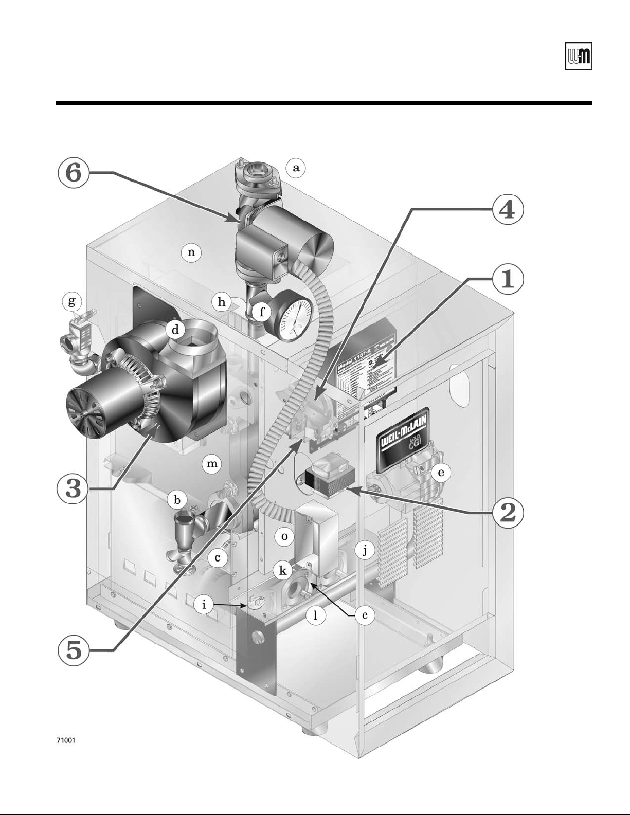
How it works . . .
Control module
①
The control module responds to signals from the room thermostat, air pressure switch and
boiler limit circuit to operate the boiler circulator, pilot burner, gas valve and inducer. When
room thermostat calls for heat, the control module starts the system circulator and inducer.
The control module runs the inducer long enough to purge the boiler flue passages, then opens
the pilot valve and activates pilot ignition spark.
The control module allows up to 15 seconds to establish pilot flame. If flame is not sensed
within 15 seconds, the control module will turn off the gas valve, flash the Flame light, and
then enter a 15-second postpurge. The control module will then start a new cycle. This will
continue indefinitely until pilot flame is established or power is interrupted. Once pilot flame
is proven, the control module opens the gas valve to allow main burner flame.
When the room thermostat is satisfied, the control module turns off the gas valve, operates the
inducer for a 15-second postpurge and waits for the next heat call.
The control module indicator lights show normal sequence when the lights are on steady. When
a problem occurs, the control module flashes combinations of lights to indicate the most likely
reason for the problem (see page 49).
Transformer
②
The control transformer reduces line voltage to 24 volts for the gas valve and limit circuit.
Inducer
③
The inducer pulls flue gases through the boiler, causing air to be pulled in through the boiler
air openings. The inducer pushes the flue gases through the vent pipe as well.
Air pressure switch
④
The air pressure switch signals the control module, telling the control module whether the
inducer is working correctly or the vent is blocked.
Water temperature limit switch
⑤
The water temperature limit switch turns off the gas valve if the temperature in the boiler goes
above its setting. (The circulator will continue to run as long as there is a call for heat.)
Boiler circulator
⑥
The boiler circulator circulates water through the external (system) piping. The circulator is
shipped loose, and can be mounted on either the boiler supply or return piping. The factoryinstalled circulator wiring harness provides ample length for either location. NOTE — The
control module provides a pump exercising routine. If the boiler is not operated for 30 days,
the control module will power the circulator for 30 seconds, then turn off.
Other boiler components:
a supply to system
b return from system
c stainless steel burners
d flue outlet
e gas valve
2
f pressure/temperature gauge
g relief valve
h air vent connection
i flame rollout thermal fuse
element (TFE)
j burner shield
k pilot burner and bracket
l gas manifold
m cast iron boiler sections
n flue collector
o junction box
Part Number 550-110-710/0107
GOLD CGi Gas-Fired Water Boiler — Boiler Manual
GOLD CGi Gas-Fired Induced-Draft Water Boiler
Part Number 550-110-710/0107
3

GOLD CGi Gas-Fired Water Boiler — Boiler Manual
Contents
How it works ....................................................2–3
Hazard definitions ...............................................
Please read before proceeding ............................
1 Prepare boiler location ...................................
2 Prepare boiler ...............................................
3
Venting ......................................................... 14-19
4 Water piping .................................................
12–13
20-29
5 Gas piping .........................................................
6 Field wiring .......................................................
7
Start-up ........................................................ 32-35
8 Check-out procedure — checklist ......................
9
Operation ..................................................... 37-42
4
5
6–11
30
31
36
10 Service and maintenance ............................. 43-47
11 Troubleshooting ............................................ 48-57
12 Replacement parts ....................................... 58-65
13 Dimensions and ratings ................................ 66-67
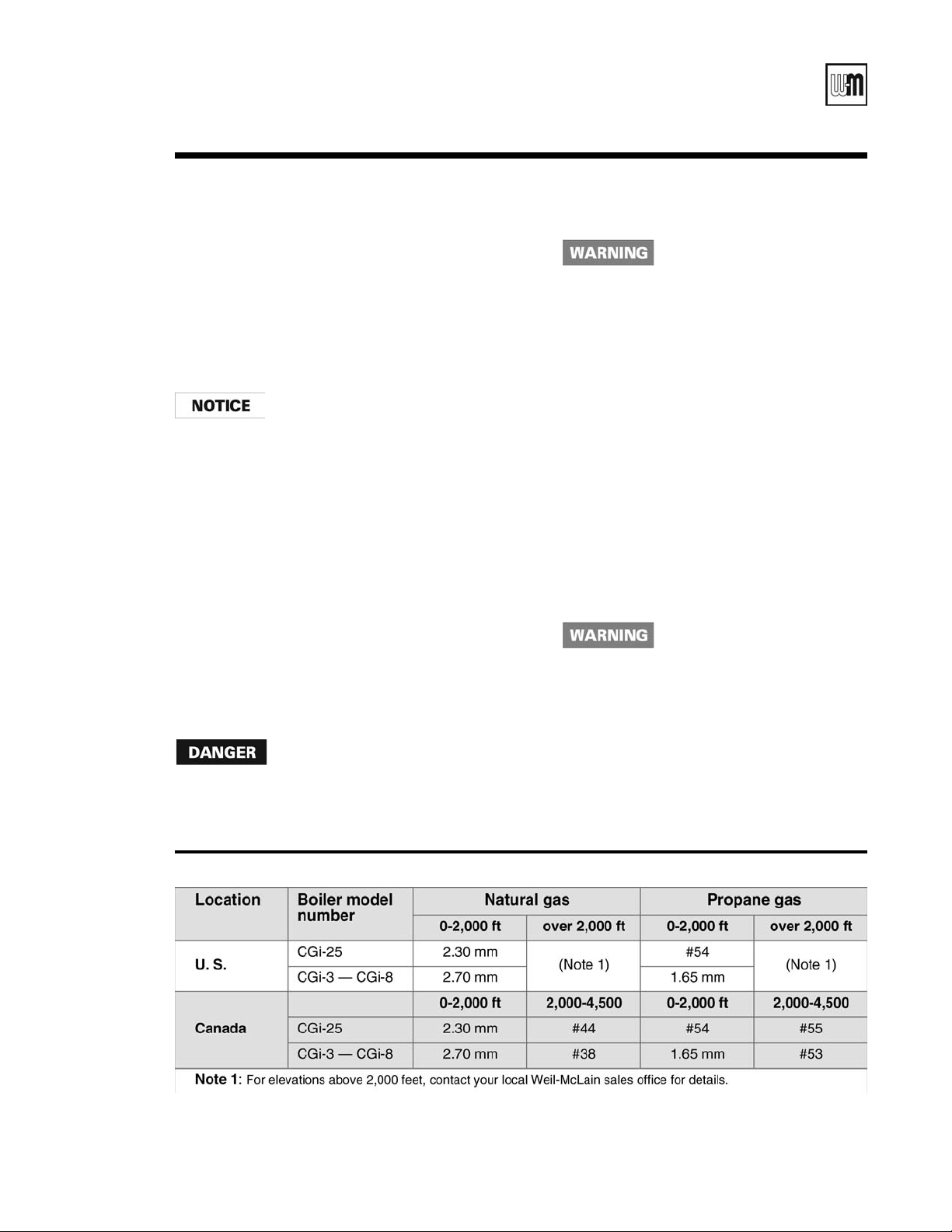
Hazard definitions
The following defined terms are used throughout this manual to bring attention to the presence of hazards of
various risk levels or to important information concerning the life of the product.
Indicates presence of hazards that will cause severe personal injury, death or substantial
property damage.
Indicates presence of hazards that can cause severe personal injury, death or substantial
property damage.
Indicates presence of hazards that will or can cause minor personal injury or property dam-
age.
Indicates special instructions on installation, operation or maintenance that are important but
not related to personal injury or property damage.
4
Part Number 550-110-710/0107
GOLD CGi Gas-Fired Water Boiler — Boiler Manual
Please read before proceeding
Installer
Read all instructions before in-
stalling. Follow all instructions in
proper order to prevent personal
injury or death.
• Consider piping and installation when determining
boiler location.
• Any claims for damage or shortage in shipment
must be filed immediately against the transportation
company by the consignee.
The boiler contains ceramic fiber and fiberglass materials. Use care when handling these
materials per instructions on page 68 of this manual. Failure to comply could result in severe
personal injury.
When calling or writing about the boiler— Please have the boiler model number from the
boiler rating label and the CP number from the boiler jacket. You may list the CP number in
the space provided on the Installation and service certificate found on page 36.
Failure to adhere to the guidelines on this page can result in severe personal injury, death
or substantial property damage.
When servicing boiler —
• To avoid electric shock, disconnect electrical supply
before performing maintenance.
• To avoid severe burns, allow boiler to cool before
performing maintenance.
Boiler operation —
• Do not block flow of combustion or ventilation air to
boiler.
• Should overheating occur or gas supply fail to shut
off, do not turn off or disconnect electrical supply to
circulator. Instead, shut off the gas supply at a location
external to the appliance.
• Do not use this boiler if any part has been under
water. Immediately call a qualified service technician
to inspect the boiler and to replace any part of the
control system and any gas control that has been under
water.
Boiler water —
• Do not use petroleum-based cleaning or sealing
compounds in boiler system. Water seal deterioration
will occur, causing leakage between sections. This can
result in substantial property damage.
• Do not use “homemade cures” or “boiler patent
medicines”. Serious damage to boiler, personnel and/or
property may result.
User
• This manual is for use only by your qualified
heating installer/service technician.
• Please refer to the User’s Information Manual for
your reference.
• We recommend regular service by a qualified
service technician, at least annually.
• Continual fresh makeup water will reduce
boiler life. Mineral buildup in sections reduces heat transfer, overheats cast iron, and
causes section failure. Addition of oxygen
and other gases can cause internal corrosion.
Leaks in boiler or piping must be repaired
at once to prevent makeup water.
• Do not add cold water to hot boiler. Thermal
shock can cause sections to crack.
Glycol — potential fire hazard —
All glycol is flammable when exposed to high
temperatures. If glycol is allowed to accumulate
in or around the boiler or any other potential
ignition source, a fire can develop. In order to
prevent potential severe personal injury, death
or substantial property damage from fire and/or
structural damage:
• Never store glycol of any kind near the boiler
or any potential ignition source.
• Monitor and inspect the system and boiler
regularly for leakage. Repair any leaks im
mediately to prevent possible accumulation
of glycol.
• Never use automotive antifreeze or ethylene
glycol in the system. Using these glycols can
lead to hazardous leakage of glycol in the
boiler system.
-
Part Number 550-110-710/0107
5
GOLD CGi Gas-Fired Water Boiler — Boiler Manual
1a
Prepare boiler location — codes & checklist
Installations must follow these codes:
• Local, state, provincial, and national codes, laws, regulations and ordinances.
• National Fuel Gas Code, ANSI Z223.1–latest edition.
• Standard for Controls and Safety Devices for Automatically Fired Boilers, ANSI/
ASME CSD-1, when required.
• National Electrical Code.
• For Canada only: B149.1 or B149.2 Installation Code, CSA C22.1 Canadian
Electrical Code Part 1 and any local co
The CGi boiler gas manifold and controls met safe lighting and
other performance criteria when boiler underwent tests specified
in ANSI Z21.13–latest edition.
Before locating the boiler, check the
following:
• Check for nearby connection to:
• System water piping
• Venting connections
• Gas supply piping
• Electrical power
• Check area around boiler.
other flammable liquids, or other contaminants.
Failure to keep boiler area clear and free of combustible mate-
rials, gasoline and other flammable liquids and vapors can
result in severe personal injury, death or substantial property
damage.
Remove any combustible materials, gasoline and
des.
• Boiler must be installed so that gas control system components are protected
from dripping or spraying water or rain during operation or service.
• If new boiler will replace existing boiler, check for and correct system problems,
such as:
1. System leaks causing oxygen corrosion or section cracks from hard water
deposits.
2. Incorrectly-sized expansion tank.
3. Lack of antifreeze in boiler water causing system and boiler to freeze and
leak.
6
Part Number 550-110-710/0107
GOLD CGi Gas-Fired Water Boiler — Boiler Manual
Minimum foundation width:
CGi-25/3 12" CGi-6 21"
CGi-4 15" CGi-7 24"
CGi-5 18" CGi-8 27"
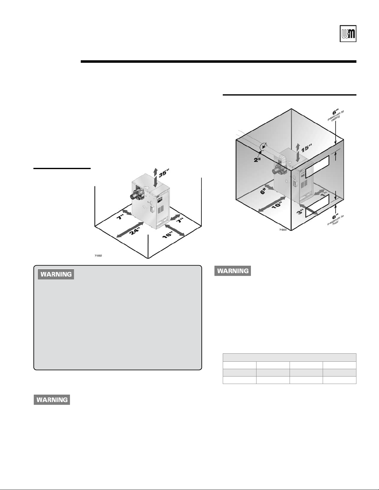
1b
Prepare boiler location — clearances
Recommended SERVICE clearances
(Fig. 1a)
1. Provide clearances for cleaning and servicing the boiler and for
access to controls and components. See Figure 1a for recommendations.
2. Provide at least screwdriver clearance to jacket front panel screws
for removal of front panel for inspection and minor service. If
unable to provide at least screwdriver clearance, install unions and
shutoff valves in system so boiler can be moved for servicing.
Figure 1a
Recommended
SERVICE clearances
(see WARNING
below)
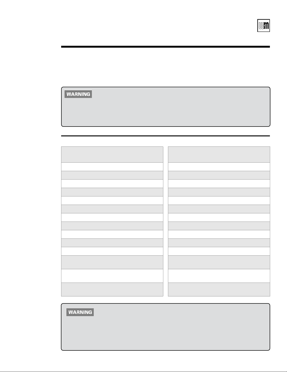
Figure 1b Required MINIMUM clearances
Flooring
The CGi boiler is approved for installation on combustible
flooring, but must never be installed on carpeting.
If any clearance is less than in Figure 1a, pro-
vide openings for combustion and ventilation
air located on the wall or door opposite the
boiler FRONT (see Figure 1b)
These openings must be located as shown in Figure 1b to provide
proper air flow around the boiler. The free area of each opening
(after deducting for louvers) must be at least one square inch per
1,000 Btuh of boiler input. If the building is of unusually tight
construction (see page 11 for definition), the air openings must
connect directly to outside or the building must have air openings
to the outside as specified on page 11.
If clearances are equal to or greater than Figure 1a, see pages 10
and 11 for location and sizing of combustion air openings.
Failure to comply can result in severe personal injury, death or
substantial property damage and reduced boiler life.
Required MINIMUM clearances (Fig. 1b)
Never install the boiler in a space with clear-
ances less than the minimum clearances shown
in Figure 1b
personal injury, death or substantial property damage and reduced boiler life.
1. Hot water pipes: at least ¹⁄₂ inch from combustible material.
2.
Single-wall vent pipe: at least 6 inches from combustible mate-
rial.
3. Type B double-wall metal vent pipe: refer to vent manufacturer’s
recommendation for clearances to combustible material.
Part Number 550-110-710/0107
. Failure to comply can result in severe
Do not install boiler on carpeting even
if foundation is used. Fire can result,
causing severe personal injury, death
.
or substantial property damage.
Foundation
1. Provide a solid brick or minimum 2-inch thick concrete
foundation pad if any of the following is true:
• floor can become flooded.
• the boiler mounting area is not level.
2. Minimum dimensions are 25” length by:
Residential garage installations
Take the following special precautions when installing the
boiler in a residential garage. If the boiler is located in a
residential garage, per ANSI Z223.1:
• Mount the boiler a minimum of
floor of the garage to assure the burner and ignition
devices will be no less than 18 inches above the floor.
• Locate or
by a moving vehicle.
protect the boiler so it cannot be damaged
18 inches above the
7

GOLD CGi Gas-Fired Water Boiler — Boiler Manual
1c
Prepare boiler location — vent system
Failure to follow all instructions can result in flue gas spillage and carbon monoxide emissions, causing severe
personal injury or death.
Inspect existing chimney before installing boiler. Failure to clean or replace perforated pipe or tile lining will cause
severe personal injury or death.
Direct exhaust venting (Category III) — Do not common vent the CGi in a direct exhaust system (Category III).
Connecting more than one appliance to a direct exhaust system will cause flue gas spillage or appliance malfunction, resulting in possible severe personal injury, death or substantial property damage.
When removing boiler from an
existing common vent system:
At the time of removal of an existing boiler, the following
steps shall be followed with each appliance remaining connected to the common venting system placed in operation,
while the other appliances remaining connected to the
common venting system are not in operation.
a. Seal any unused openings in the common venting
system.
b. Visually inspect the venting system for proper size
and horizontal pitch and determine there is no blockage
or restriction, leakage, corrosion or other deficiencies
which could cause an unsafe condition.
c. Test vent system — Insofar as is practical, close all
building doors and windows and all doors between
the space in which the appliances remaining connected
to the common venting system are located and other
spaces of the building. Turn on clothes dryers and any
appliance not connected to the common venting system.
Turn on any exhaust fans, such as range hoods and
bathroom exhausts, so they will operate at maximum
speed. Do not operate a summer exhaust fan. Close
fireplace dampers.
d. Place in operation the appliance being inspected.
Follow the lighting/operating instructions. Adjust
thermostat so appliance will operate continuously.
e. Test for spillage at draft hood relief opening after 5
minutes of main burner operation. Use the flame of a
match or candle.
f. After it has been determined that
remaining connected to the common venting system
properly vents when tested as outlined above, return
doors, windows, exhaust fans, fireplace dampers, and
any other gas-burning appliance to their previous conditions of use.
Any improper operation of common venting system should
be corrected so the installation conforms with the National
Fuel Gas Code, ANSI Z223.1-latest edition. Correct by re
sizing to approach the minimum size as determined using
the appropriate tables in Part 11 of that code. Canadian
installations must comply with B149.1 or B149.2 Installation Code.
each appliance
Chimney or vent requirements
1. Venting must be installed according to Part 7,
Venting of Equipment, of National Fuel Gas
Code, ANSI Z223.1-latest edition and applicable building codes. Canadian installations
must comply with B149.1 or B149.2 Installation
Codes.
2. See Ratings table on page 67 for minimum chim
ney or vent sizes. A chimney or vent without a
listed cap should extend at least 3 feet above
the highest point where it passes through a roof
of a building and at least 2 feet higher than
any portion of a building within a horizontal
distance of 10 feet. A chimney or vent must not
extend less than the distances stated above.
3. A lined chimney is preferred and must be used
when required by local, state, provincial and
national codes, laws, regulations and ordinances.
Vitreous tile linings with joints that prevent
retention of moisture and linings made of non
corrosive materials are best. Advice for flue connections and chimney linings can be obtained
from local gas utility. Type B double-wall metal
vent pipe or single-wall vent pipe may be used
as a liner.
4. Cold masonry chimneys, also known as outside
chimneys, typically have one or more walls ex
posed to outside air. When any atmospheric
gas-fired boiler with automatic vent damper
is vented through this type of chimney, the
potential exists for condensation to occur. Condensation can damage a masonry chimney. WeilMcLain recommends the following to prevent
possible damage.
a. Line chimney with corrosion-resistant
metal liner such as AL29-4C® single-wall
-
stainless steel or B-vent. Size liner per Na
tional Fuel Gas Code ANSI Z223.1-latest
edition.
b. Provide drain trap to remove any conden
sate.
-
-
-
-
-
8
Part Number 550-110-710/0107
GOLD CGi Gas-Fired Water Boiler — Boiler Manual
Products to avoid Areas likely to have contaminants
Spray cans containing chloro/fluorocarbons Dry cleaning/laundry areas and establishments
Permanent wave solutions Swimming pools
Chlorinated waxes/cleaners Metal fabrication plants
Chlorine-based swimming pool chemicals Beauty shops
Calcium chloride used for thawing Refrigeration repair shops
Sodium chloride used for water softening Photo processing plants
Refrigerant leaks Auto body shops
Paint or varnish removers Plastic manufacturing plants
Hydrochloric acid/muriatic acid Furniture refinishing areas and establishments
Cements and glues New building construction
Antistatic fabric softeners used in clothes dryers Remodeling areas
Chlorine-type bleaches, detergents, and cleaning
solvents found in household laundry rooms
Garages with workshops
Adhesives used to fasten building products and
other similar products
Buildings under construction (where air is
contaminated with particulates)
Airborne particulates (drywall dust, fiberglass
particles, road or gravel dust, lint, etc.)
1d
Prepare boiler location — air contamination
Please review the following information on potential
combustion air contamination problems.
To prevent potential of severe personal injury or death, check for products or areas listed
below before installing boiler. If any of these contaminants are found:
• remove contaminants permanently
— OR —
• isolate boiler and provide outside combustion air. See national, provincial or local codes
for further information.
Table 1 Corrosive or destructive contaminants and likely locations
Refer to Table 1 for products and areas which may cause
contaminated combustion air.
Part Number 550-110-710/0107
CONSTRUCTION DUST HAZARD — Airborne particulates, such as drywall dust
or fiberglass dust, will cause blockage of the CGi burners, resulting in carbon monoxide
production, a fire hazard, or building freeze damage. If the boiler is operated during
construction, you must isolate the boiler to provide clean air for combustion. If you are
unable to ensure uncontaminated air in the boiler vicinity at all times, you must
inspect the boiler at least once weekly. When inspecting, clean the burners if necessary
using the procedure given on page 45. Failure to follow these guidelines could result in
severe personal injury, death or substantial property damage.
9
GOLD CGi Gas-Fired Water Boiler — Boiler Manual
1e
✷
If all clearances are at least equal to Figure 1a,
If ANY clearance is less than Figure 1a, page 7,
Prepare boiler location — air openings
Combustion air opening location and sizing
requirements depend on the clearances around
the boiler. Check the boiler placement compared to
Figure 1a, page 7.
, apply the sizing and placement of openings
page 7
given on pages 10 and 11.
you must provide air openings sized and located as
shown in Figure 1b, page 7. DO NOT apply the sizing
and location information shown on page 10 or 11.
Air openings must be provided
Combustion air and ventilation openings must comply the National Fuel
Gas Code ANSI Z223.1-latest edition, or applicable local building codes.
Canadian installations must comply with B149.1 or B149.2 Installation
Codes.
Provide adequate combustion and ventilation air to
assure proper combustion and reduce the risk of severe
personal injury, death or substantial property damage
caused by flue gas spillage and carbon monoxide
emissions.
Air opening options
Two openings — Air supply from inside the building
1. If the building is of unusually tight construction (see definition, next
page), the building must also be provided with air openings directly
to the outside, sized and located per Figure 3, Figure 4 or Figure 5.
2. Buildings of typical construction should provide adequate combustion
air from natural infiltration, so additional air openings to the building
are not required.
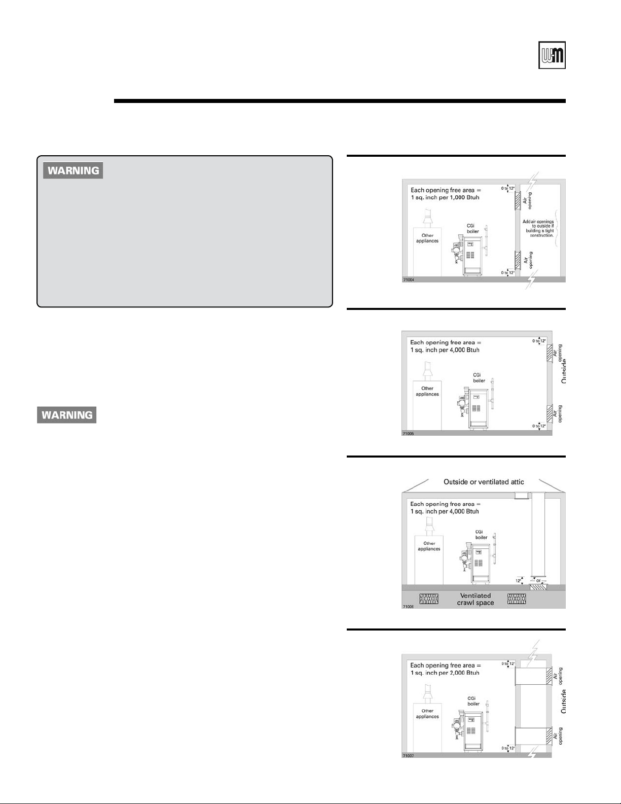
3. See Figure 2. Provide two openings through the interior wall, within
12 inches of the ceiling and the floor, sized per Figure 2.
✷
Figure 2 Air openings to interior spaces
✷
Figure 3 Air directly through outside wall
✷
Figure 4 Air from outdoors — vertical ducts
✷
Two openings — Air supply directly from outside
1. Air openings must be directly through an outside wall, or into a space
that connects directly to the outside (such as a ventilated attic or crawl
space, for example).
2. See Figure 3 — Openings directly through an outside wall — provide
two openings within 12 inches of the ceiling and the floor, sized per
Figure 3.
3. See Figure 4 — Air supplied through vertical ducts — provide two
openings terminated within 12 inches of the ceiling and the floor, sized
per Figure 4.
4. See Figure 5 — Air supplied through horizontal ducts — provide
two openings within 12 inches of the floor and the ceiling, sized per
Figure 5.
10
✷
Figure 5 Air from outdoors — horizontal ducts
✷
Part Number 550-110-710/0107
GOLD CGi Gas-Fired Water Boiler — Boiler Manual
FREE AREA of openings — the minimum areas
given in this manual are free area (equals the area,
length times width of opening, after deduction for
louver obstruction).
Use the free area information provided by the louver manufacturer.
When this information is not available, assume:
• Wood louvers — assume free area is 20% of total; so the actual area
of each opening with wood louvers would be 5 times the required
free area.
• Metal louvers — assume free area is 60% of actual area; so, for wood
louvers, the actual area of each opening must be 1.67 times the
required free area.
Single air opening option
A single combustion air opening can be used in lieu of the two-opening
options on page 10, provided:
Clearances from boiler to walls
• The boiler must have clearances of at least those shown in Figure 1a,
page 7.
Opening must be directly to outside
• The opening must connect directly to the outdoors or to a space that
communicates directly to the outdoors (not to an interior space).
• The air can be provided through a direct opening or through a horizontal
or vertical duct.
Opening placement
• The top of the air opening must be within 12 inches of the ceiling.
Opening size
• The free area of the opening must be at least equal to the sum of the
areas of all equipment vent connectors in the space, and . . .
• The free area of the opening must be at least 1 square inch per 3,000
Btu/hr input rating of all equipment located in the space.
Exception for large spaces
No combustion air openings are needed when the boiler (and other appliances) are installed in a space with a volume at least 50 cubic feet per
1,000 Btuh of all installed appliances, provided:
• the building must not have unusually tight construction (see defini-
tion, this page)
• all clearances around the boiler must must be no less than shown in
Figure 1a, page 7.
To determine if the space is large enough to qualify:
• Add the total input of all appliances in MBH (1,000’s of Btuh).
• Multiply this number times 50 to determine minimum room volume.
• Example: For a total input of 100 MBH (100,000 Btuh), minimum
volume is 50 x 100 = 5,000 cubic feet. At a ceiling height of 8 feet, the
space must have at least 5,000 ÷ 8 = 625 square feet (25 feet x 25 feet,
for instance).
✷
✷
Unusually tight construction
Unusually tight construction means (per ANSI Z223.1)
buildings in which:
a. Walls and ceilings exposed to the outside atmo-
sphere have a continuous water vapor retarder with
a rating of 1 perm or less with openings gasketed,
and . . .
b. Weather-stripping has been added on openable
windows and doors, and . . .
c. Caulking or sealants are applied to areas such as
joints around windows and door frames, between
sole plates and floors, between wall-ceiling joints,
between wall panels, at penetrations for plumbing,
electrical, and gas lines, and in other openings.
For such construction cases, if appliances use inside air
for combustion, provide air openings into the building
from outside. Size and locate these openings per the
appropriate case in Figure 3, 4 or 5 on page 10.
Exhaust fans and air movers
The appliance space must never be under a negative
pressure, even if the appliance(s) are installed as direct
vent. Always provide air openings sized not only to the
dimensions required for the firing rate of all appliances, but also to handle the air movement rate of the
exhaust fans or air movers using air from the building
or space.
Motorized air dampers
If the air openings are fitted with motorized dampers,
electrically interlock the damper to:
• Prevent the boiler from firing if the damper is not
fully open.
• Shut the boiler down should the damper close during boiler operation.
To accomplish this interlock, wire an isolated contact
(proving the damper open) in series with the thermostat input to the boiler. The boiler will not start if this
contact is open, and will shut down should it open
during operation.
Part Number 550-110-710/0107
11
GOLD CGi Gas-Fired Water Boiler — Boiler Manual
Prepare boiler — placement & setup2a
Place boiler/crate near
position
1. Leave boiler in crate and on pallet until installation site
is ready.
2. Move entire crate and pallet next to selected location.
3. Remove crate.
4. Remove boiler from pallet.
Do not drop boiler or bump jacket on
floor or pallet. Damage to boiler can
result.
a. Tilt left side of boiler up and place a board under
left legs.
b. Tilt boiler the other way and place a board under
right legs.
c. Slide boiler backward off pallet and into position.
5. Check level.
a. Shim legs, if necessary.
b. Do not alter legs.
Inspect orifices and burners
1. Remove front jacket door. Remove burner shield (see
Figure 40, item 4, page 60).
2. Check for correctly-sized manifold orifices. See
for sizing. (The orifice size is stamped on the orifice
spud barrel.)
Correctly-sized manifold orifices must
be used. Failure to do so will result in
severe personal injury, death or substantial property damage.
3. Reinstall burner shield.
Table 2
Do not operate boiler without
burner shield in place. Failure
to do so could result in severe
personal injury, death or substantial property damage.
Orifice replacement
procedure
(when required)
1. Remove the screws securing the burner shield
and remove burner shield.
2. Using a
burner orifices from the manifold.
3. Apply a small amount of pipe dope to each of
the new orifices and install in the manifold us
ing a 7/16” open-end wrench. Make sure the orifices are aligned correctly, not cross-threaded
in the manifold tappings.
4. Carefully replace the burner shield.
5. Follow the check-out procedure, Section
page 36, to assure the boiler is now operating
properly after orifices are replaced.
7
/16” open-end wrench, remove the
Use only pipe dope compatible
with propane gas, even if boiler
is to be operated on natural gas.
Failure to comply could result
in severe personal injury, death
or substantial property damage.
-
8
12
Table 2 Manifold orifice sizing at sea level and altitudes to 4,500 feet
Part Number 550-110-710/0107
GOLD CGi Gas-Fired Water Boiler — Boiler Manual
2b
Prepare boiler — pressure test
Hydrostatic pressure test
Pressure test boiler before attaching water or gas piping
(except as noted below) or electrical supply.
Prepare boiler for test
1. Remove the shipping nipple (from CGi supply tap-
ping) and remove the boiler relief valve. Temporarily
plug the relief valve tapping with a ¾” NPT pipe
plug.
2. Remove 1¼” nipple, reducing tee and drain valve
from circulator hardware and pressure/temperature
gauge carton. Install in boiler return connection as
shown on page 3 and Figure 42, page 64. Install
circulator on either the return or supply.
3. Remove 1¼” nipple, 1¼” x 1¼” x ½” tee and pres
sure/temperature gauge from circulator hardware
and pressure/temperature gauge carton. Pipe to
boiler supply connection as shown on page 3 and
Figure 42, page 64. (Use pipe dope sparingly.)
4. Connect a hose to boiler drain valve, the other end
connected to a fresh water supply. Make sure hose
can also be used to drain boiler after test.
5. Connect a nipple and shutoff valve to system supply
connection on the 1¼” tee. This valve will be used
to bleed air during the fill. (Valve and nipple are not
included with boiler.)
6. Connect a nipple and shutoff valve to system re-
turn connection (at circulator flange if circulator
installed on return). This valve will be used to bleed
air during the fill. (Valve and nipple are not included
with boiler.)
Fill and pressure test
1. Open the shutoff valves you installed on supply and
return connections.
2. Slowly open boiler drain valve and fresh water sup
ply to fill boiler with water.
3. When water flows from shutoff valves, close boiler
drain valve.
4. Close shutoff valves.
5. Slowly reopen boiler drain valve until test pressure
on the pressure/temperature gauge reaches no more
than:
• 45 psig for boilers with 30 psig relief valve.
• 75 psig for boilers with 50 psig relief valve.
6. Test for no more than 10 minutes at:
• 45 psig for boilers with 30 psig relief valve.
• 75 psig for boilers with 50 psig relief valve.
Do not leave boiler unattended.
-
7. Make sure constant gauge pressure has been main
tained throughout test. Check for leaks. Repair if
found.
Leaks must be repaired at once.
Do not use petroleum-based clean-
Drain and remove fittings
1. Disconnect fill water hose from water source.
2. Drain boiler at drain valve or out hose, whichever
provides best access to drain. Remove hose after
-
draining if used to drain boiler.
3. Remove nipples and valves unless they will remain
for use in the system piping.
4. Remove plug from relief valve tapping. See page 20
to replace relief valve.
A cold water fill could expand and
cause excessive pressure, resulting
in severe personal injury, death or
substantial property damage.
-
Failure to do so can damage boiler,
resulting in substantial property
damage.
ing or sealing compounds in boiler
system. Severe damage to boiler
will occur, resulting in substantial
property damage.
Part Number 550-110-710/0107
13
GOLD CGi Gas-Fired Water Boiler — Boiler Manual
Venting — general information3a
CGi venting methods — Chimney draft or Direct exhaust
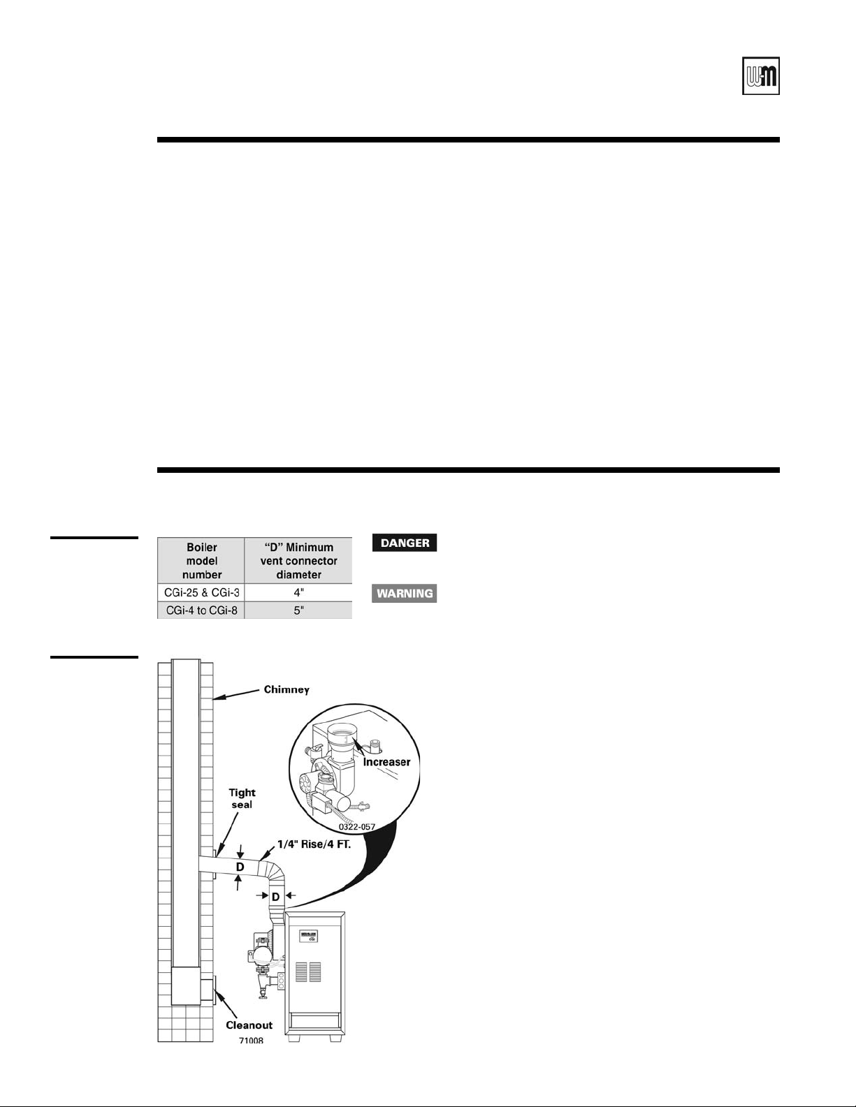
Table 3
Vent
connector
diameter
Chimney draft venting
Chimney draft venting uses the natural draft provided
by a vertical vent or chimney. Category I appliance (nonpositive vent static pressure and vent gas temperature
that avoids excessive condensate production in vent).
See Section 3b. Chimney draft installations use:
1. Vent connector (single or doublewall) sized to
eliminate positive pressure in vent system. Diameter
increases immediately at boiler.
2. Doublewall metal vent (B-vent) or chimney with
liner approved by the National Fuel Gas Code, ANSI
Z223.1–latest edition, or in Canada B149.1 or B149.2
Installation Code.
Venting — chimney draft venting3b
Inspect existing chimney before installing boiler. Failure to
clean or replace perforated pipe or lining will cause severe
personal injury or death.
Vent sizing given in Table 3 is only a general guideline. The
vent connector and chimney must be designed, sized and
constructed in compliance with all applicable codes. Failure to
correctly size and install the vent system could result in severe
personal injury, death or substantial property damage.
Direct exhaust — vertical or sidewall
Direct exhaust venting uses inside combustion air with
no combustion air connector piping. All CGi flue gas
vents are pressurized, requiring careful sealing of all
joints. Category III appliance (positive vent static pressure and vent gas temperature that avoids excessive
condensate production in vent). See pages 15-19.
Direct exhaust installations use:
1. Vent pipe specified in this manual.
2. Vent termination through outside wall, roof or un
used chimney. Tight chimney areas will make vent
joint construction very difficult.
-
14
Figure 7
Chimnney
draft
venting
1. Use doublewall metal vent (B-vent) or chimney with liner as
required by the National Fuel Gas Code, ANSI Z223.1–latest
edition, or in Canada, B149.1 or B149.2 Installation Code.
2. To prevent downdrafts, chimney should extend at least 3 feet
above the highest point where it passes through a roof and
at least 2 feet higher than any portion of a building within
a horizontal distance of 10 feet.
3. To vent with another appliance, see National Fuel Gas Code,
ANSI Z223.1–latest edition or in Canada B149.2 or B149.2
Installation Code
4. Do not connect breeching to any portion of a mechanical
draft system that can operate under positive pressure.
5. Maintain minimum 2” clearance from combustible materials
to vent pipe.
6. Do not use chimney with an open fireplace.
7. Make horizontal runs as short as possible. Long runs can
cause condensation.
8. When longer runs are used, support pipe with appropriate
hangers.
9. To prevent blockage, do not vent into bottom of chimney.
10. Vent pipe must not go beyond inside wall of chimney.
11. Vent passing through floors or ceilings must be fire
stopped.
12. See
Figure 7 and Table 3 to connect boiler to venting sys-
tem.
Part Number 550-110-710/0107
-
GOLD CGi Gas-Fired Water Boiler — Boiler Manual
Venting — Direct exhaust — components3c
Obtain vent system components
1. The following special gas vent systems comply with UL-1738 and ULCS636 standards and are certified by CSA as the only systems suitable for
use with CGi boilers (all 3” diameter):
• Heat-Fab, Inc.
• Flex-L International, Inc. StaR-34
• Z-Flex®, Inc. Z-Vent II
• ProTech Systems FasNSeal™
Use only the vent starter of the same manufacturer as
2. Select vent method based on page 14 and installation requirements.
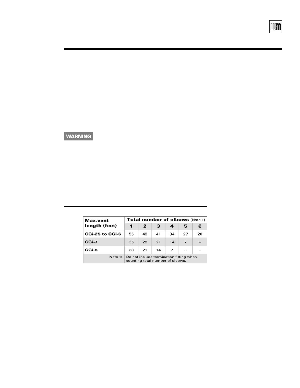
3. Refer to
Do not exceed data in Table 4.
4. Select vent components from separate
Supplement. All components, including the vent starter, must be of
the same vent manufacturer. Do not mix components.
Table 4 for maximum vent run lengths and number of elbows.
Saf-T Vent
the vent components. Do not mix components from
different systems. The vent system could fail, causing
flue gas spillage, resulting in severe personal injury or
death.
®
CGi, Cgs & GV Vent Component
Table 4 Maximum vent length
Part Number 550-110-710/0107
15
GOLD CGi Gas-Fired Water Boiler — Boiler Manual
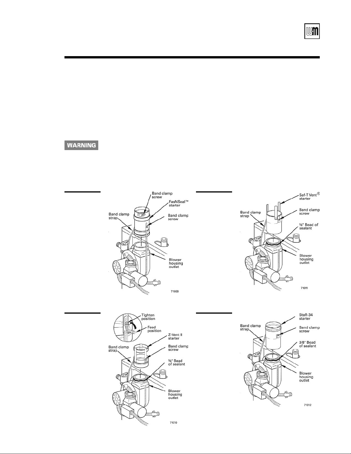
Venting — direct exhaust — vent starter3d
1. Select a vent pipe manufacturer and obtain all vent
components needed, based on boiler location and
venting method.
2. You must use the vent starter made by the vent pipe
manufacturer. See separate
Component Supplement, for part number of each
CGi, CGs & GV Vent
component, listed by vent manufacturer.
Use only the vent starter of the same
manufacturer as the vent components. Do not mix components
from different systems. The vent
system could fail, causing flue gas
spillage, resulting in severe personal
injury or death.
Figure 8
FasNSeal™
ventstarter
3. Follow all applicable national, state, local or provincial codes when venting the CGi boiler.
4. Connect vent starter to blower housing outlet as
shown in the
Figures 8 through 11.
a. Do not mix components from different vent
manufacturers.
b. Maintain minimum 2” clearance from com
-
bustible materials to vent pipe.
c. Seal with sealant specified by vent pipe
manufacturer, using
³⁄₈" bead (not required for
FasNSeal™).
d. Tighten strap at band clamp screw until strap
is snug around blower housing.
Figure 10
Saf-T Vent®
vent starter
16
Figure 9
Z-Vent II
vent starter
Figure 11
StaR-34
vent starter
Part Number 550-110-710/0107
GOLD CGi Gas-Fired Water Boiler — Boiler Manual
Venting — direct exhaust — termination3e
Follow instructions on this page
when determining vent location to
avoid possibility of severe personal
injury, death or substantial property
damage.
1. Locate the boiler and vent penetration through the
wall so all requirements on this page and in Fig
ure 12 will be met. Also follow vent manufacturer’s
instructions.
2. Gases will form white plume in winter. Plume could
obstruct window view.
3. Prevailing winds could cause freezing of condensate
and water/ice buildup on vent termination, building,
plants or roof. Ice buildup on vent termination can
cause boiler shutdown and building freezeup.
4. Winds over 31 mph can cause nuisance boiler shut
down if boiler is sidewall vented. This could result
in loss of heat to building, causing freezeup.
5. Locate or guard vent termination to prevent con
densate from damaging exterior surfaces.
6. Locate the vent termination well away from trees,
shrubs, and decorative items.
7. Locate or guard vent to prevent accidental contact
by people or pets.
8. Do not terminate vent in window well, stairwell,
alcove, courtyard, or other recessed areas.
9. Do not wrap or insulate vent pipe or fittings.
10. Do not terminate vent above any door or window.
Condensate can freeze, causing ice formations.
11. Do not connect:
• Any other appliance to vent pipe.
• Multiple boilers to a common vent pipe.
12. Canadian installations — See B149.1 or B149.2
Installation Code. Terminate vent no less than 6
feet from another combustion air inlet, 3 feet from
any other building opening, and 3 feet from any gas
service regulator.
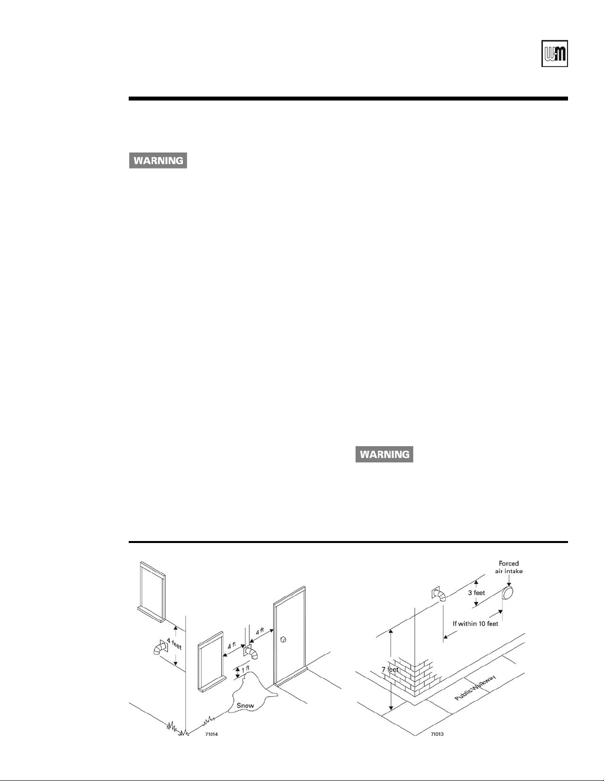
13. See
-
14. Vent must also terminate:
-
-
15. Site conditions may dictate greater clearances.
16. Do not extend exposed vent pipe outside of building.
Figure 12, showing that the vent must termi-
nate:
• more than 4 feet below or to side of all doors
or windows.
• more than 1 foot above grade or anticipated
snow line.
• at least 7 feet above public walkway.
• 3 feet above any forced air intake within 10
feet.
• at least 6 feet away from adjacent walls.
• no closer than 5 feet below roof overhang.
• at least 4 feet horizontally (and in no case
above or below unless a 4 foot horizontal
distance is maintained) from electric meters,
gas meters, regulators, relief valves, and other
equipment.
Condensate could freeze and block vent pipe.
A gas vent extending through an
exterior wall shall not terminate adjacent to the wall or below building
extensions such as eaves, parapets,
balconies or decks. Failure to comply could result in severe personal
injury, death or substantial property
damage.
Figure 12 Vent termination minimum clearances
Part Number 550-110-710/0107
17
GOLD CGi Gas-Fired Water Boiler — Boiler Manual
Venting — direct exhaust — installation3f
1. Do not mix types or manufacturers of vent materials.
2. Clean all joints before sealing. See vent manufacturer’s instructions for cleaning and sealing joints. Use
their specified sealant. Do not use screws.
3. Install vent pipe with seams on top of vent horizontal runs. Follow requirements in Section 3e for vent
termination.
4. Maintain minimum 2” clearance from combustible
materials to vent pipe.
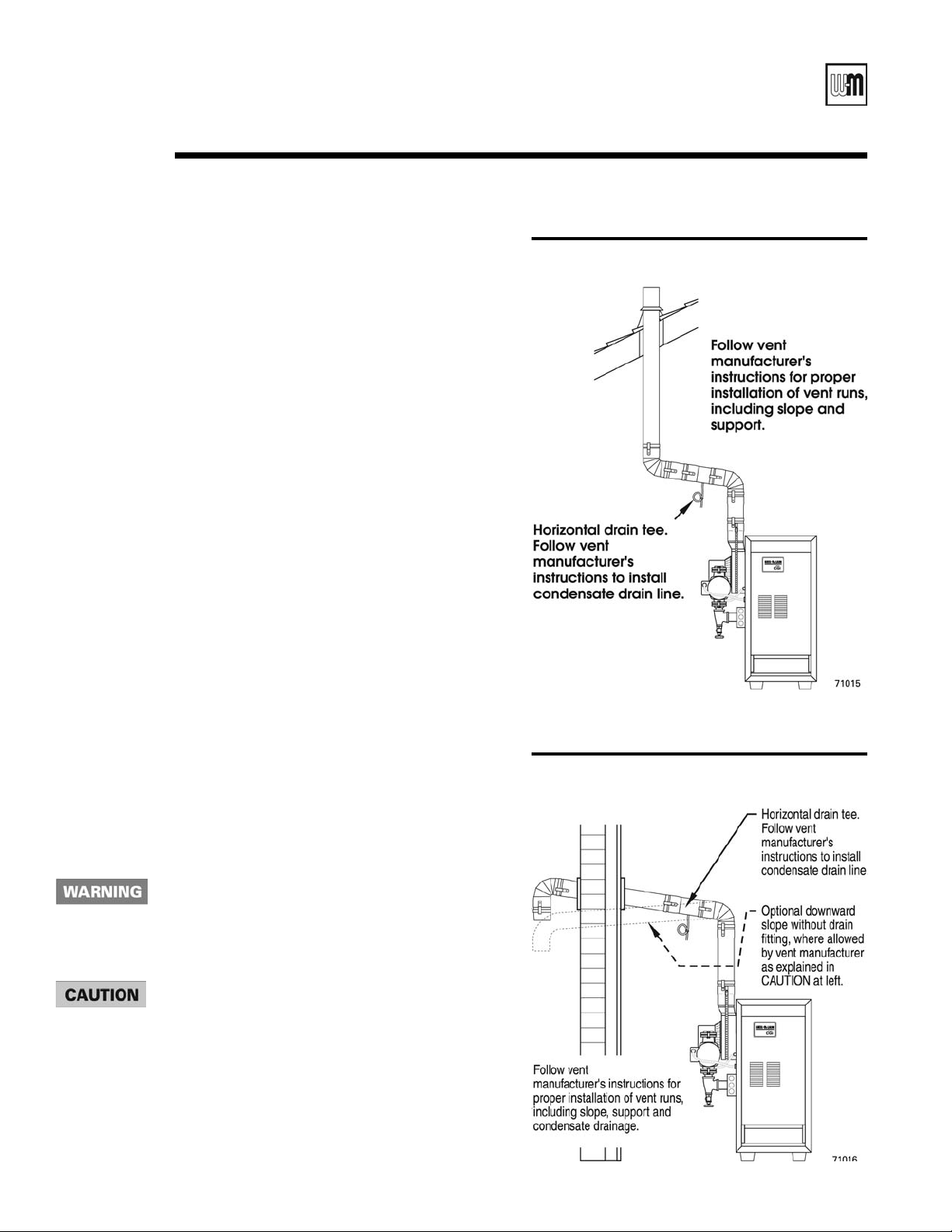
5. Vertical venting — See Figure 13. Follow vent
manufacturer’s instructions for venting through
roof.
• Vent pipe must extend through roof flashing,
jacket or thimble.
• Vent may pass through floor, inside wall or
concealed space when installed according to
vent manufacturer’s instructions.
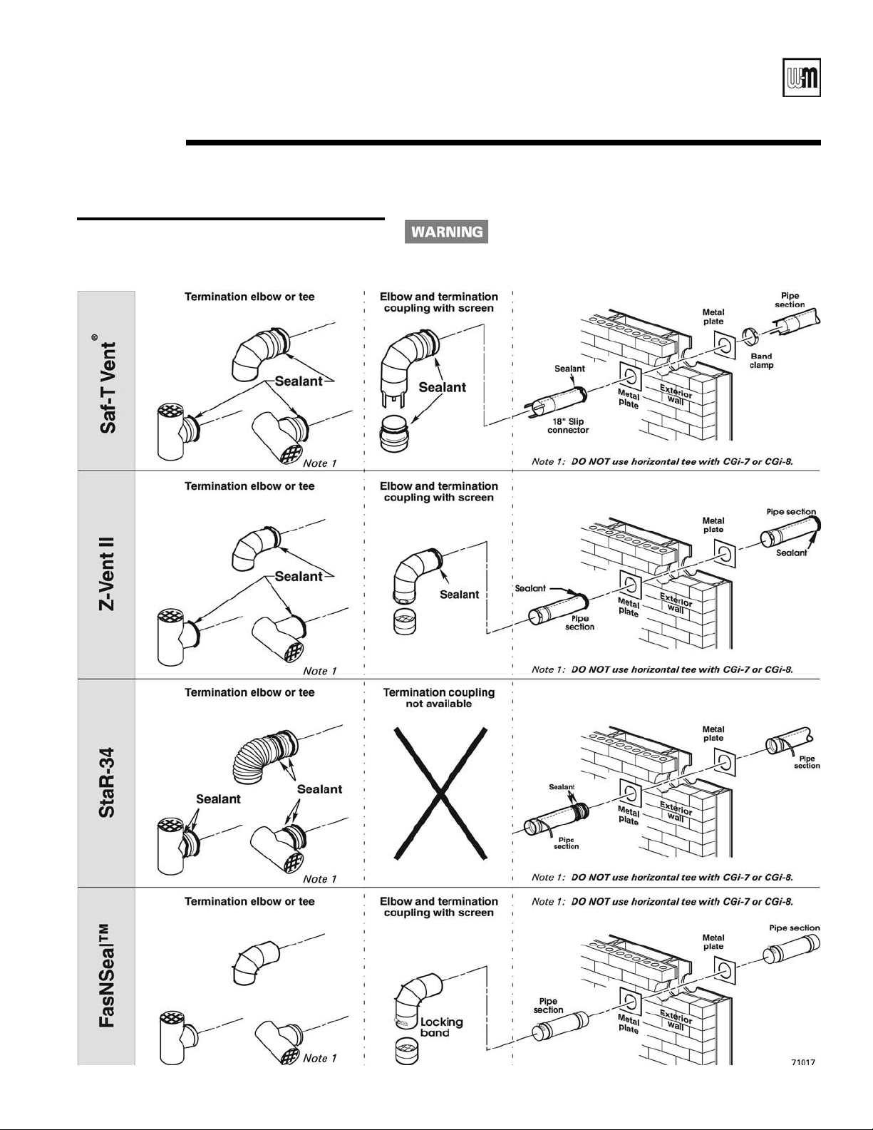
Sidewall venting — See Figures 14 and 15.
Vent must terminate at least one foot above
anticipated snowline. Vent must be terminated
only with:
• Tee or elbow with integral screen. (Tee may be
mounted either vertically or horizontally. DO
NOT use horizontal tee with CGi-7 or CGi-8.)
• Elbow and termination coupling with screen
(not available for StaR-34).
6. Do not seal vent pipe (slip connector for Saf-T Vent)
to inside or outside plate.
7. If passing through noncombustible wall, provide
hole diameter large enough to insert the vent pipe
(slip connector for Saf-T Vent).
8. Install horizontal drain tee as close as possible
to boiler, in first horizontal run. See Figures 13
.
and 14
9. Do not exceed the maximum vent system length
given in Table 4, page 15.
Condensate drain line — use only silicone tubing rated
for at least 400°F for the first 18” of condensate drain
line, then other non-metallic tubing may be used. Using any other material could cause flue gas leakage,
potentially resulting in severe personal injury, death or
substantial property damage.
On some installations, the condensate drain fitting may
be omitted, provided:
• Vent manufacturer shows this option in their instruc-
tions.
• Vent is sloped toward termination as shown in dotted
lines in Figure 14.
• The vent is installed per Weil-McLain and vent
manufacturer’s instructions.
• Condensate drippage from such vents may accumu-
late on the ground below. Consider traffic in the area
to avoid hazard due to ice accumulation.
Figure 13 Direct exhaust vertical venting
Figure 14 Direct exhaust sidewall venting
18
Part Number 550-110-710/0107
GOLD CGi Gas-Fired Water Boiler — Boiler Manual
3f
Figure 15 Sidewall termination
Venting — direct exhaust — installation (cont.)
Using any termination other than one of those shown
could cause nuisance outages and loss of heat, resulting
in substantial property damage.
Part Number 550-110-710/0107
19
GOLD CGi Gas-Fired Water Boiler — Boiler Manual
Boiler
model number
To
system
From
system
CGi-25 ¾" ¾"
CGi-3, 4, 5 1" 1"
CGi-6, 7 1¼" 1¼"
CGi-8 1½" 1½"
Note: The boiler supply and return connections, the return/
drain tee and the supply/gauge tee supplied with the
boiler are 1¼” NPT. One of the circulator flanges supplied with the boiler is 1¼”. The other circulator flange
is the size of the recommended system piping shown
above.
Water piping — general information4a
General piping information
If installation is to comply with ASME or Canadian requirements, an additional high temperature limit is needed. Install control in supply piping
between boiler and isolation valve. Set second control to minimum 20°F
above setpoint of first control. Maximum allowable setpoint is 240°F. See
Section 9b for wiring.
A low water cutoff device is required when boiler is installed above ra-
diation level or by certain state or local codes or insurance companies. Use
low water cutoff designed for water installations. Electrode probe-type is
recommended. Purchase and install in tee in supply piping above boiler.
Use backflow check valve in cold water supply as required by local
codes.
Pressure/temperature gauge
Install pressure/temperature gauge in tee on supply piping (as shown in
drawing on page 3).
Relief valve
Install relief valve vertically in ¾” tapping on side of boiler. See Figure 16
or 17, page 21, and the tag attached to the relief valve for manufacturer’s
instructions.
Circulator
The circulator is shipped loose (wiring pre-attached to
boiler) to allow you to locate it either in the return or
supply piping, as desired. See page 3 for a typical installation. Pipe the expansion tank to the suction side of the
circulator whenever possible. Install an air separator in
the supply piping. Connect the expansion tank to the air
separator only if the separator is on the suction side of
the circulator. Always install the system fill connection
at the same point as the expansion tank connection to
the system. Figures 16 and 17 show typical near-boiler
piping connections.
System water piping
See Figure 16 (diaphragm-type or bladder-type expan-
sion tank) or Figure 17 (closed-type expansion tank)
and Table 6, for near-boiler and single-zone systems
designed for return water at least 130°F.
See pages 22-23 to complete multiple-zone piping or
pages 24-29 to complete piping for radiant heating
systems or converted gravity systems (large-volume
systems originally designed for circulation by natural
convection rather than a pump). See page 29 for boilers
used with refrigeration systems.
To avoid water damage or scalding due to relief valve
operation:
• Discharge line must be connected to relief valve outlet and run to a
safe place of disposal. Terminate the discharge line to eliminate
possibility of severe burns should the valve discharge.
• Discharge line must be as short as possible and be the same size as
the valve discharge connection throughout its entire length.
• Discharge line must pitch downward from the valve and terminate
at least 6” above the floor drain where any discharge will be clearly
visible.
• The discharge line shall terminate plain, not threaded, with a mate-
rial serviceable for temperatures of 375°F or greater.
• Do not pipe the discharge to any place where freezing could
occur.
• No shutoff valve shall be installed between the relief valve and boiler,
or in the discharge line. Do not plug or place any obstruction in the
discharge line.
• Failure to comply with the above guidelines could result in failure of
the relief valve to operate, resulting in possibility of severe personal
injury, death or substantial property damage.
• Test the operation of the valve after filling and pressurizing system
by lifting the lever. Make sure the valve discharges freely. If the valve
fails to operate correctly, replace it with a new relief valve.
20
Table 6 Water pipe size (based on 20°F rise)
Chillers or air handling units:
Install boiler such that —
• Chilled medium, if used, is piped in parallel with
heating boiler. Use appropriate valves to prevent
chilled medium from entering boiler. Consult
I=B=R Installation and Piping Guides.
• If boiler is connected to heating coils located in
air handling units where they can be exposed to
refrigerated air, use flow control valves or other automatic means to prevent gravity circulation during
cooling cycle. Circulation of cold water through the
boiler could result in damage to the heat exchanger,
causing possible severe personal injury, death or
substantial property damage.
Part Number 550-110-710/0107
GOLD CGi Gas-Fired Water Boiler — Boiler Manual
Water piping — single-zone system4b
Undersized expansion tanks cause system water to be lost from relief valve and makeup water
to be added through fill valve. Eventual section failure can result.
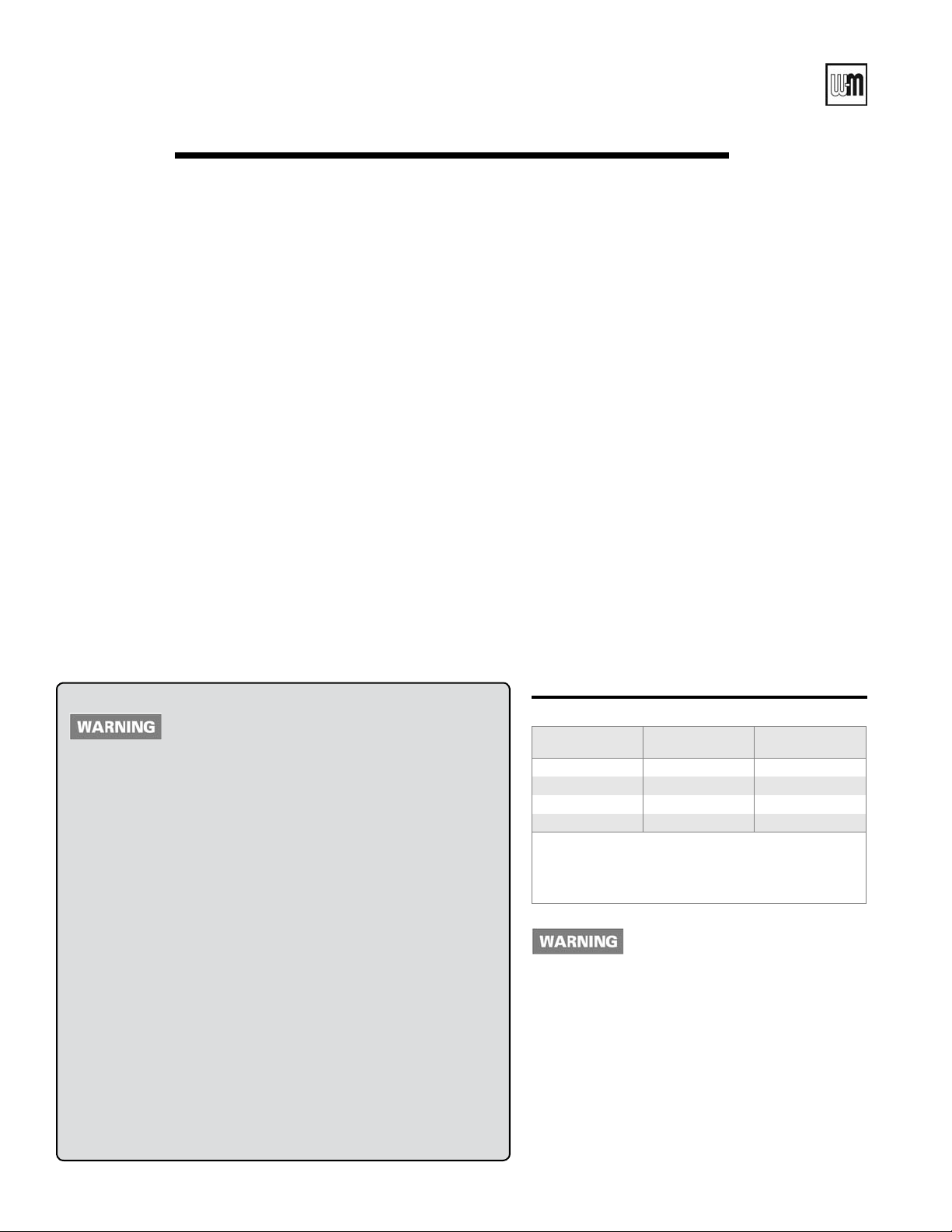
Diaphragm-type or bladdertype expansion tank (Figure 16)
1. Ensure expansion tank size will handle boiler and
system water volume and temperature. Tank must
be located in boiler return piping as close to boiler
as possible, before inlet side of circulator. See tank
manufacturer’s instructions for details.
2. Install an
Figure 16 Diaphragm- or bladder-type expansion
automatic air vent as shown.
Use Figure 16 or Figure 17 only for single-zone systems designed for return water at least 130°F.
For systems with low return water temperature possible, such as converted gravity systems
and radiant heating systems, refer to the special piping suggestions of pages 24-29. Failure to
prevent low return water temperature to the boiler could cause corrosion of the boiler sections
or burners, resulting in severe personal injury, death or substantial property damage.
tank — Piping to single-zone system
using diaphragm-type or bladder-type
expansion tank. See Table 6 for piping
sizes.
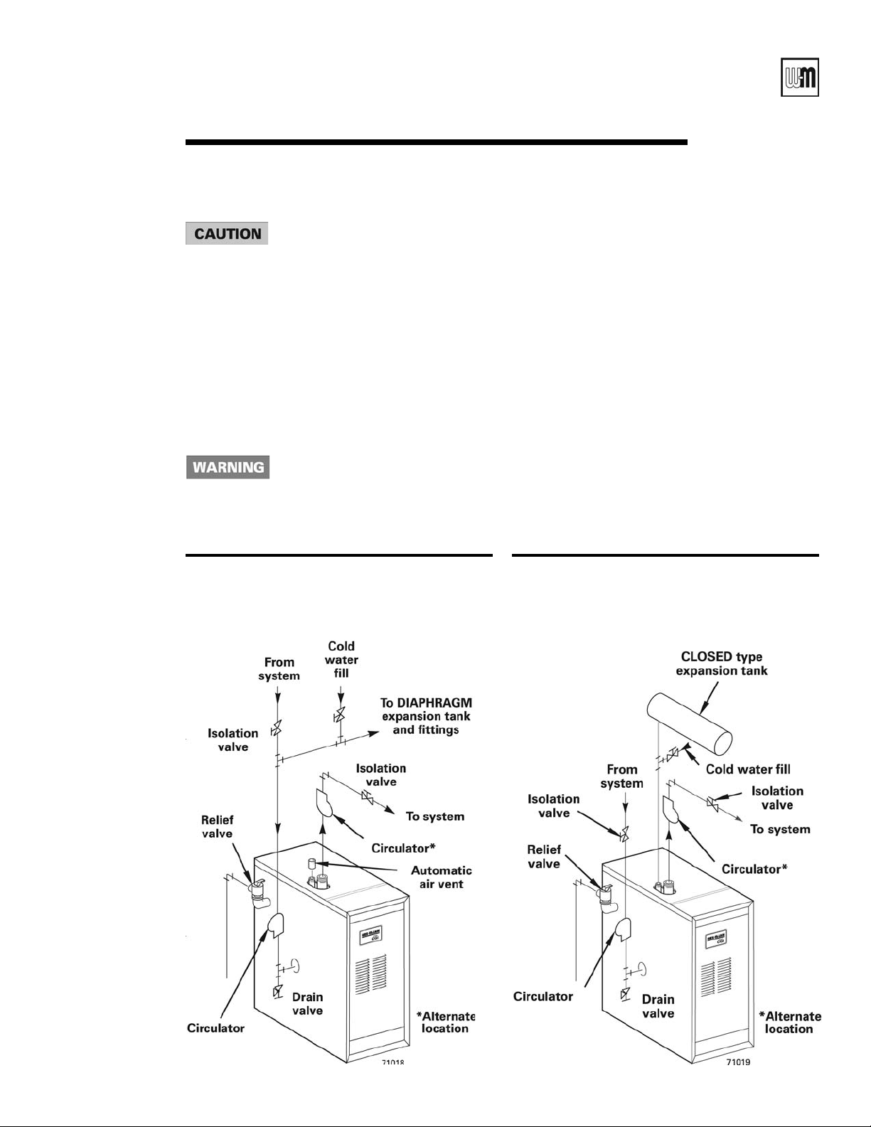
Closed-type expansion tank
(Figure 17)
1. Ensure expansion tank size will handle boiler and
system water volume and temperature. See tank
manufacturer’s instructions for details.
2. Connect tank to ½” NPT tapping located behind
supply outlet, using ½” NPT piping. Pitch any
horizontal piping up towards tank 1 inch per 5 feet
of piping.
Figure 17 Closed-type expansion tank — Piping
to single-zone system using closedtype expansion tank. See Table 6 for
piping sizes.
Part Number 550-110-710/0107
21
 Loading...