

Page 1
Page 2

GOLD CGi Series 2 Gas-Fired Water Boiler
How it works . . .
①
②
③
Control module
The control module responds to signals from the room thermostat, air pressure switch and
boiler limit circuit to operate the boiler circulator, pilot burner, gas valve and inducer. When
room thermostat calls for heat, the control module starts the system circulator and inducer.
The control module runs the inducer long enough to purge the boiler flue passages, then
opens the pilot valve and activates pilot ignition spark.
The control module allows up to 15 seconds to establish pilot flame. If flame is not sensed
within 15 seconds, the control module will turn off the gas valve, flash the Flame light, and
then enter a 15-second postpurge. The control module will then start a new cycle. This will
continue indefinitely until pilot flame is established or power is interrupted. Once pilot flame
is proven, the control module opens the gas valve to allow main burner flame.
When the room thermostat is satisfied, the control module turns off the gas valve, operates
the inducer for a 15-second postpurge and waits for the next heat call.
The control module indicator lights show normal sequence when the lights are on steady.
When a problem occurs, the control module flashes combinations of lights to indicate the
most likely reason for the problem (see page 47).
Transformer
The control transformer reduces line voltage to 24 volts for the gas valve and limit circuit.
Inducer
The inducer pulls flue gases through the boiler, causing air to be pulled in through the boiler
air openings. The inducer pushes the flue gases through the vent pipe as well.
④
⑤
Air pressure switch
The air pressure switch signals the control module, telling the control module whether the
inducer is working correctly or the vent is blocked.
Water temperature limit switch
The water temperature limit switch turns off the gas valve if the temperature in the boiler
goes above its setting. (The circulator will continue to run as long as there is a call for heat.)
Boiler circulator
The boiler circulator circulates water through the external (system) piping. The circulator is
shipped loose, and can be mounted on either the boiler supply or return piping. The factoryinstalled circulator wiring harness provides ample length for either location. NOTE — The
control module provides a pump exercising routine. If the boiler is not operated for 30 days,
the control module will power the circulator for 30 seconds, then turn off.
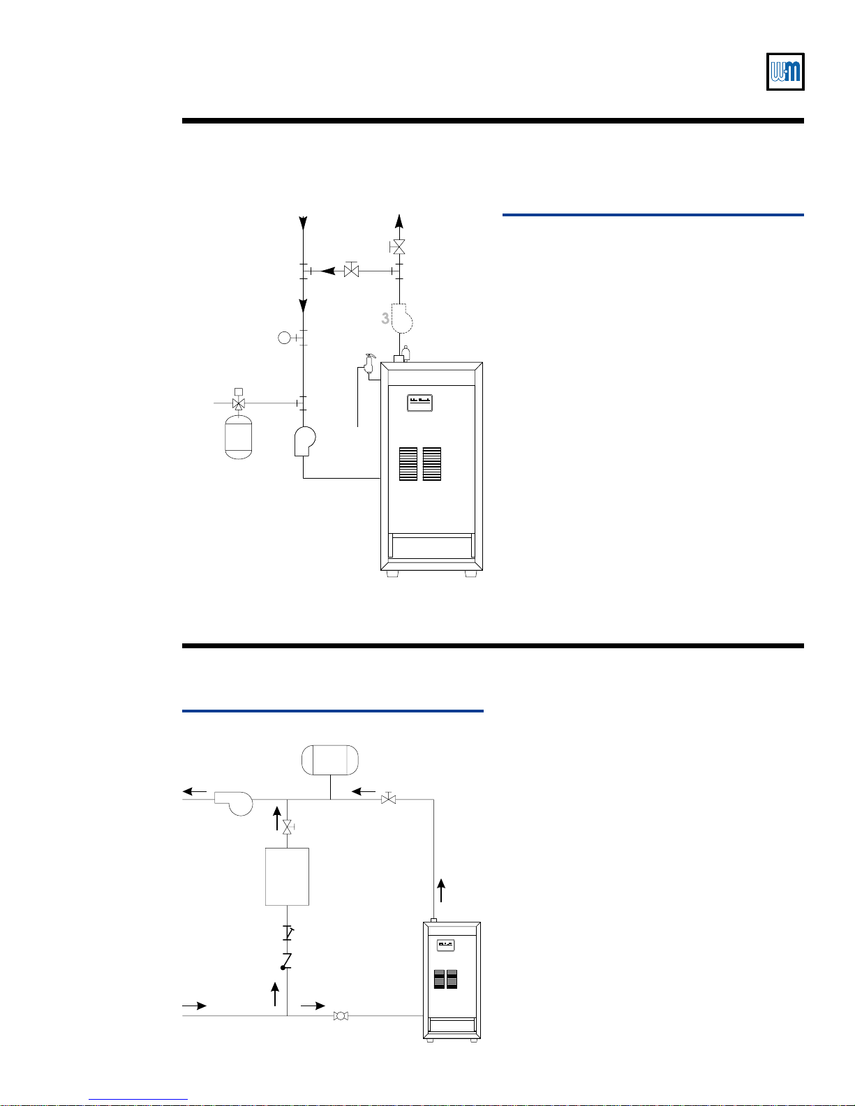
Other boiler components:
a supply to system
b return from system
c stainless steel burners
d flue outlet
e gas valve
f pressure/temperature gauge
g relief valve
h air vent connection
i flame rollout thermal fuse
element (TFE)
j burner shield
k pilot burner and bracket
l gas manifold
m cast iron boiler sections
n flue collector
o junction box
2
Part Number 550-110-710/0200
Page 3
Page 4
GOLD CGi Series 2 Gas-Fired Water Boiler
Contents
How it works .................................................................. 2–3
Hazard definitions.............................................................. 4
Please read before proceeding ......................................... 5
Prepare boiler location ................................................ 6–11
1
Prepare boiler............................................................. 12–13
2
Venting ........................................................................14-19
3
Water piping ............................................................... 20-29
4
Gas piping ........................................................................ 30
5
Field wiring ...................................................................... 31
6
Start-up .......................................................................32-35
7
Check-out procedure....................................................... 36
8
Operation ....................................................................37-40
9
Service and maintenance........................................... 41-45
10
Troubleshooting ......................................................... 46-55
11
Replacement parts ..................................................... 56-61
12
Dimensions and ratings .............................................62-63
13
Hazard definitions
The following defined terms are used throughout this manual to bring attention to the presence of hazards of
various risk levels or to important information concerning the life of the product.
Indicates presence of hazards that will cause severe personal injury, death or substantial
property damage.
Indicates presence of hazards that can cause severe personal injury, death or substantial
property damage.
Indicates presence of hazards that will or can cause minor personal injury or property damage.
Indicates special instructions on installation, operation or maintenance that are important
but not related to personal injury or property damage.
4
Part Number 550-110-710/0200
Page 5

Boiler Manual
Please read before proceeding
Installer
Read all instructions before
installing.
proper order to prevent personal
injury or death.
• Consider piping and installation when
determining boiler location.
• Any claims for damage or shortage in shipment
must be filed immediately against the transportation company by the consignee.
When calling or writing about the boiler— Please have the boiler model number from the
boiler rating label and the CP number from the boiler jacket. You may list the CP number in
the space provided on the Installation and service certificate found on page 36.
Failure to adhere to the guidelines on this page can result in severe personal injury, death
or substantial property damage.
When servicing boiler —
• To avoid electric shock, disconnect electrical
supply before performing maintenance.
• To avoid severe burns, allow boiler to cool before
performing maintenance.
Boiler operation —
• Do not block flow of combustion or ventilation
air to boiler.
• Should overheating occur or gas supply fail to
shut off, do not turn off or disconnect electrical
supply to circulator. Instead, shut off the gas
supply at a location external to the appliance.
• Do not use this boiler if any part has been under
water. Immediately call a qualified service
technician to inspect the boiler and to replace any
part of the control system and any gas control
that has been under water.
Boiler water —
• Do not use petroleum-based cleaning or sealing
compounds in boiler system. Water seal
deterioration will occur, causing leakage between
sections. This can result in substantial property
damage.
• Do not use "homemade cures" or "boiler patent
medicines". Serious damage to boiler, personnel
and/or property may result.
Follow all instructions in
User
• This manual is for use only by your qualified
heating installer/service technician.
• Please refer to the User’s Information Manual for
your reference.
• We recommend regular service by a qualified
service technician, at least annually.
• Continual fresh makeup water will reduce boiler
life. Mineral buildup in sections reduces heat
transfer, overheats cast iron, and causes section
failure. Addition of oxygen and other gases can
cause internal corrosion. Leaks in boiler or piping
must be repaired at once to prevent makeup
water.
• Do not add cold water to hot boiler. Thermal
shock can cause sections to crack.
Glycol — potential fire hazard —
All glycol is flammable when exposed to high
temperatures. If glycol is allowed to accumulate in
or around the boiler or any other potential ignition
source, a fire can develop. In order to prevent
potential severe personal injury, death or substantial
property damage from fire and/or structural damage:
• Never store glycol of any kind near the boiler or
any potential ignition source.
• Monitor and inspect the system and boiler
regularly for leakage. Repair any leaks
immediately to prevent possible accumulation
of glycol.
• Never use automotive antifreeze or ethylene
glycol in the system. Using these glycols can lead
to hazardous leakage of glycol in the boiler
system.
Part Number 550-110-710/0200
5
Page 6
GOLD CGi Series 2 Gas-Fired Water Boiler
1a
Prepare boiler location —
Installations must
follow these codes:
• Local, state, provincial, and national codes, laws, regulations and
ordinances.
• National Fuel Gas Code, ANSI Z223.1–latest edition.
• Standard for Controls and Safety Devices for Automatically Fired
Boilers, ANSI/ASME CSD-1, when required.
• National Electrical Code.
• For Canada only: B149.1 or B149.2 Installation Code, CSA C22.1
Canadian Electrical Code Part 1 and any local codes.
The CGi boiler gas manifold and controls met safe
lighting and other performance criteria when boiler
underwent tests specified in ANSI Z21.13–latest
edition.
codes & checklist
Before locating the boiler,
check the following:
• Check for nearby connection to:
• System water piping
• Venting connections
• Gas supply piping
• Electrical power
• Check area around boiler. Remove any combustible materials, gasoline
and other flammable liquids.
Failure to keep boiler area clear and free of combustible
materials, gasoline and other flammable liquids and
vapors can result in severe personal injury, death or
substantial property damage.
• Boiler must be installed so that gas control system components are
protected from dripping or spraying water or rain during operation
or service.
• If new boiler will replace existing boiler, check for and correct system
problems, such as:
1. System leaks causing oxygen corrosion or section cracks from
hard water deposits.
2. Incorrectly-sized expansion tank.
3. Lack of antifreeze in boiler water causing system and boiler to
freeze and leak.
6
Part Number 550-110-710/0200
Page 7

Boiler Manual
Boiler
model
Minimum
foundation
length
Minimum
foundation
width
CGi-25 25" 12"
CGi-3 25" 12"
CGi-4 25" 15"
CGi-5 25" 18"
CGi-6 25" 21"
CGi-7 25" 24"
CGi-8 25" 27"
Prepare boiler location — clearances1b
Provide the following clearances:
1. Hot water pipes — at least ½" from combustible
materials.
2. Recommended service clearances — See
3. Minimum clearances for tight spaces — See
Figure 2.
Figure 1 Recommended clearances for service
35"
7"
24"
18"
71002
Figure 1.
7"
Flooring and foundation
Flooring
The CGi boiler is approved for installation on
combustible flooring, but must never be installed on
carpeting.
Do not install boiler on carpeting
even if foundation is used. Fire can
result, causing severe personal
injury, death or substantial property
damage.
Foundation
Provide a solid brick or
concrete foundation pad if any of the following is true:
• floor can become flooded.
• the boiler mounting area is not level.
The minimum foundation size is:
minimum 2-inch thick
Figure 2 Minimum clearances for tight spaces
2"
6"
Part Number 550-110-710/0200
71003
Provide
openings
and 6" from bottom located
on wall next to boiler front..
(2) fresh air
— 6" from top
Each opening must have
free area of square
inch per of
1
1,000 Btuh
CGi boiler input.
Residential garage installation
Precautions
Take the following special precautions when installing
the boiler in a residential garage. If the boiler is located
in a residential garage, per ANSI Z223.1, paragraph
5.1.9:
• Mount the boiler a minimum of
above the floor
of the garage to assure the
burner and ignition devices will be no less
than 18 inches above the floor.
• Locate or protect the boiler so it cannot be
damaged by a moving vehicle.
18 inches
7
Page 8
GOLD CGi Series 2 Gas-Fired Water Boiler
1c
Prepare boiler location — vent system
CGi venting
Failure to follow all instructions can
result in flue gas spillage and carbon
monoxide emissions, causing
severe personal injury or death.
Inspect existing chimney before
installing boiler. Failure to clean or
replace perforated pipe or tile lining
will cause severe personal injury or
death.
Do not install the CGi into a
common vent with any other
appliance. This will cause flue gas
spillage or appliance malfunction,
resulting in possible severe personal
injury, death or substantial property
damage.
When removing boiler from existing
common vent system:
At the time of removal of an existing boiler, the
following steps shall be followed with each appliance
remaining connected to the common venting system
placed in operation, while the other appliances
remaining connected to the common venting system
are not in operation.
a. Seal any unused openings in the common venting
system.
b. Visually inspect the venting system for proper
size and horizontal pitch and determine there is
no blockage or restriction, leakage, corrosion or
other deficiencies which could cause an unsafe
condition.
c.
Test vent system — Insofar as is practical, close
all building doors and windows and all doors
between the space in which the appliances
remaining connected to the common venting
system are located and other spaces of the building.
Turn on clothes dryers and any appliance not
connected to the common venting system. Turn on
any exhaust fans, such as range hoods and
bathroom exhausts, so they will operate at
maximum speed. Do not operate a summer exhaust
fan. Close fireplace dampers.
d. Place in operation the appliance being inspected.
Follow the operating instructions. Adjust
thermostat so appliance will operate continuously.
Test for spillage at draft hood relief opening after
e.
5 minutes of main burner operation. Use the flame
of a match or candle.
f. After it has been determined that each appliance
remaining connected to the common venting
system properly vents when tested as outlined
above, return doors, windows, exhaust fans,
fireplace dampers, and any other gas-burning
appliance to their previous conditions of use.
Any improper operation of common venting system
should be corrected so the installation conforms with
the National Fuel Gas Code, ANSI Z223.1–latest
edition. Correct by resizing to approach the minimum
size as determined using the appropriate tables in Part
11 of that code. Canadian installations must comply
with B149.1 or B149.2 Installation Code.
Chimney or vent requirements
1. Venting must be installed according to Part 7,
Venting of Equipment, of National Fuel Gas Code,
ANSI Z223.1–latest edition and applicable building
codes. Canadian installations must comply with
B149.1 or B149.2 Installation Codes.
2. See Ratings table on page 67 for minimum chimney
or vent sizes. A chimney or vent
cap
should extend at least 3 feet above the highest
where it passes through a roof of a building
point
and
at least 2 feet higher than any portion of a
building within a horizontal distance of 10 feet
chimney or vent must not extend less than the
distances stated above.
3. A lined chimney is preferred and must be used
when required by local, state, provincial and
national codes, laws, regulations and ordinances.
Vitreous tile linings with joints that prevent
retention of moisture and linings made of
noncorrosive materials are best. Advice for flue
connections and chimney linings can be obtained
from local gas utility.
pipe or single-wall vent pipe may be used as a liner.
4. Cold masonry chimneys, also known as outside
chimneys, typically have one or more walls exposed
to outside air.When any atmospheric gas-fired
boiler with automatic vent damper is vented
through this type of chimney, the potential exists
for condensation to occur. Condensation can
damage a masonry chimney. Weil-McLain
recommends the following to prevent possible
damage.
a. Line chimney with corrosion-resistant metal
liner such as AL29-4C® single-wall stainless steel
or B-vent. Size liner per National Fuel Gas Code
ANSI Z223.1–latest edition.
b. Provide drain trap to remove any condensate.
Type B double-wall metal vent
without a listed
. A
8
Part Number 550-110-710/0200
Page 9
Boiler Manual
1d
Prepare boiler location — contamination
Air contamination
Please review the following information on potential
combustion air contamination problems.
If the boiler is installed in any area likely to cause contamination, or if products which
would contaminate the air cannot be removed, you must either remove products permanently
or isolate the boiler and provide outside combustion air. Contaminated combustion air will
damage the boiler, resulting in possible severe personal injury, death or substantial property
damage.
Table 1 Corrosive contaminants
Products to avoid Areas likely to have contaminants
Spray cans containing chloro/fluorocarbons Dry cleaning/laundry areas and establishments
Permanent wave solutions Swimming pools
Refer to Table 1 for products and areas which may cause
contaminated combustion air.
Chlorinated waxes/cleaners Metal fabrication plants
Chlorine-based swimming pool chemicals Beauty shops
Calcium chloride used for thawing Refrigeration repair shops
Sodium chloride used for water softening Photo processing plants
Refrigerant leaks Auto body shops
Paint or varnish removers Plastic manufacturing plants
Hydrochloric acid/muriatic acid Furniture refinishing areas and establishments
Cements and glues New building construction
Antistatic fabric softeners used in clothes dryers Remodeling areas
Chlorine-type bleaches, detergents, and cleaning
solvents found in household laundry rooms
Garages with workshops
Adhesives used to fasten building products and
other similar products
Part Number 550-110-710/0200
9
Page 10
GOLD CGi Series 2 Gas-Fired Water Boiler
Other
appliances
Air
opening
Air
opening
0 to 12"
0 to 12"
Outside
Each opening free area =
1 sq. inch per 4,000 Btuh
71005
CGi
boiler
MODEL
CGi
Prepare boiler location — air openings1e
Combustion air and ventilation openings must comply
with Section 5.3, Air for Combustion and Ventilation ,
of National Fuel Gas Code ANSI Z223.1–latest edition,
or applicable local building codes. Canadian
installations must comply with B149.1 or B149.2
Installation Codes.
Provide adequate combustion and
ventilation air to assure proper
combustion and reduce the risk of
severe personal injury, death or
substantial property damage caused
by flue gas spillage and carbon
monoxide emissions.
Air from inside building
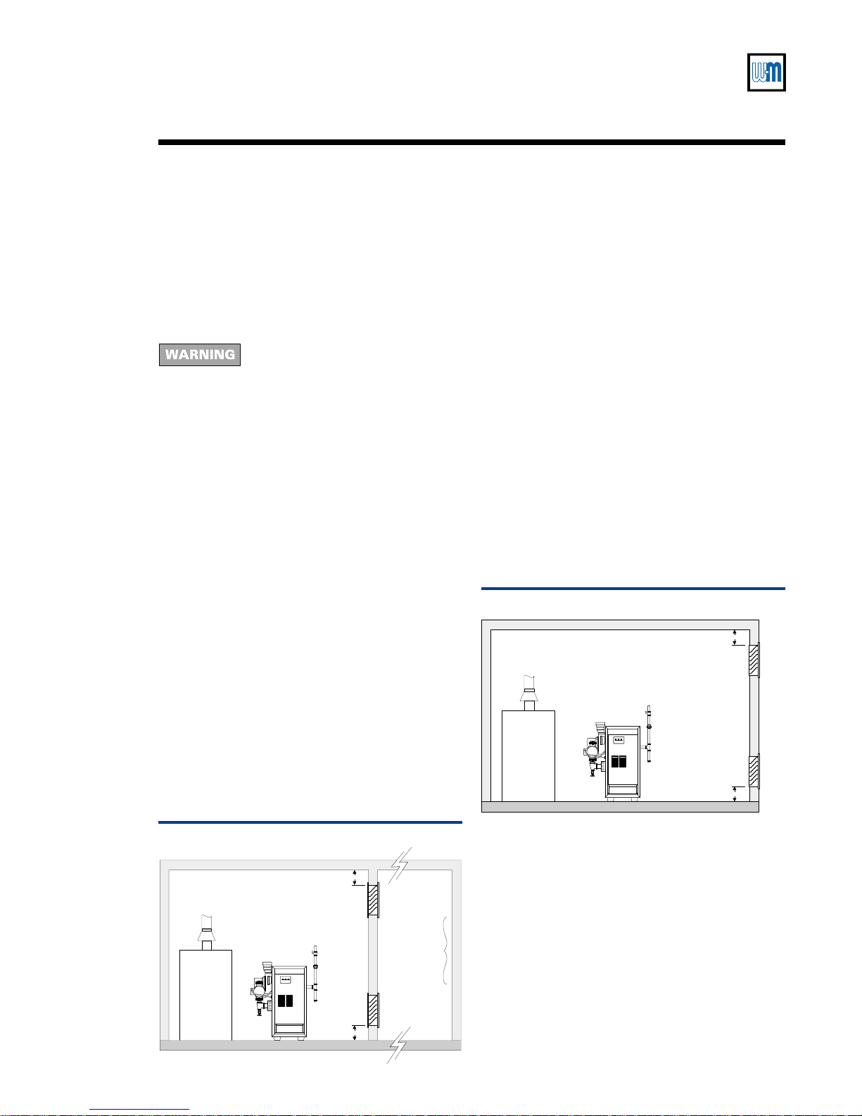
(boiler in interior room - Figure 3)
1. Tightly constructed buildings must be provided
with openings to outside for combustion and
ventilation air. These openings must be sized to
handle all fuel burning appliances, exhaust or
ventilation fans and fireplaces.
2. When openings to boiler room are taken to interior
spaces, provide two permanent openings:
• One air opening within 12 inches of floor.
• A second opening within 12 inches of ceiling.
Air directly from outside to boiler
room
1. Tightly constructed buildings must be provided
with combustion and ventilation air openings to
boiler room, which are adequate to handle the
boiler needs plus the needs of all other fuel burning
appliances, exhaust or ventilation fans and
fireplaces.
2. When combustion air is supplied to the boiler
directly through outside walls (Figure 4):
space
Provide two permanent openings:
• One air opening within 12 inches of floor.
• A second opening within 12 inches of ceiling.
Each opening must provide a minimum free area
of 1 square inch per 4,000 Btuh of input of all
appliances in room plus requirements for any
exhaust fans in room. The interior space supplying
combustion and ventilation air must have adequate
infiltration from outside.
Figure 4 Air directly from outdoors
Each opening must provide a minimum free area
of 1 square inch per 1,000 Btuh of input of
all appliances in room plus requirements for any
exhaust fans in room. The interior space supplying
combustion and ventilation air must have adequate
infiltration from outside.
Figure 3 Air openings to interior space
Each opening free area =
1 sq. inch per 1,000 Btuh
71004
Other
appliances
10
CGi
boiler
MODEL
CGi
0 to 12"
0 to 12"
Air
opening
Add air openings
to outside if
building is tight
construction.
Air
opening
3. When combustion air is supplied to the boiler
space directly from outside or ventilated attic/
crawl space through vertical ducts (Figure 5)
Provide two permanent openings:
• One air opening within 12 inches of floor.
• A second opening within 12 inches of ceiling.
Each opening must provide a minimum free area
1 square inch per 4,000 Btuh of input of all
of
appliances in room plus requirements for any
exhaust fans in room. The duct cross sectional area
must be no less than the required area of the
permanent openings.
Part Number 550-110-710/0200
:
Page 11

Boiler Manual
O
s
de
Figure 5 Air from outdoors — vertical ducts
Outside or ventilated attic
Each opening free area =
1 sq. inch per 4,000 Btuh
CGi
Other
appliances
boiler
MODEL
CGi
— or —
12"
Ventilated
71006
crawl space
4. When combustion air is supplied to the boiler
space directly from outside through horizontal
ducts (Figure 6)
: Provide two permanent openings:
• One air opening within 12 inches of floor.
• A second opening within 12 inches of ceiling.
Special considerations
Tight construction
ANSI Z223.1 defines unusually tight construction
where:
a. Walls and ceilings exposed to the outside
atmosphere have a continuous water vapor retarder
with a rating of 1 perm or less with openings
gasketed, and . . .
b. Weather-stripping has been added on openable
windows and doors, and . . .
c. Caulking or sealants are applied to areas such as
joints around windows and door frames, between
sole plates and floors, between wall-ceiling joints,
between wall panels, at penetrations for plumbing,
electrical, and gas lines, and in other openings.
For buildings with such construction, provide air
openings into the building from outside, sized per the
appropriate case in
inside air for combustion and ventilation.
Figure 4 if appliances are to use
Each opening must provide a minimum free area
1 square inch per 2,000 Btuh of input of all
of
appliances in room plus requirements for any
exhaust fans in room. The duct cross sectional area
must be no less than the required area of the
permanent openings.
Figure 6 Air from outdoors — horizontal
ducts
Each opening free area =
1 sq. inch per 2,000 Btuh
Other
appliances
71007
CGi
boiler
MODEL
CGi
0 to 12"
0 to 12"
Exhaust fans and air movers
The appliance space must never be under a negative
pressure, even if the appliance(s) are installed as direct
vent. Always provide air openings sized not only to
the dimensions required for the firing rate of all
appliances, but also to handle the air movement rate of
the exhaust fans or air movers using air from the
building or space.
Air
opening
i
ut
Air
opening
Part Number 550-110-710/0200
11
Page 12

GOLD CGi Series 2 Gas-Fired Water Boiler
Prepare boiler — placement & setup2a
Place boiler/crate near position
1. Leave boiler in crate and on pallet until installation
site is ready.
2. Move entire crate and pallet next to selected
location.
3. Remove crate.
4. Remove boiler from pallet.
Do not drop boiler or bump jacket
on floor or pallet. Damage to boiler
can result.
a. Tilt left side of boiler up and place a board
under left legs.
b. Tilt boiler the other way and place a board
under right legs.
c. Slide boiler backward off pallet and into
position.
5. Check level.
a. Shim legs, if necessary.
b. Do not alter legs.
Inspect orifices and burners
1. Remove front jacket door. Remove burner shield
(see
Figure 40, item 4, page 58).
2. Check for correctly-sized manifold orifices. See
Table 2 for sizing. (The orifice size is stamped on
the orifice spud barrel.)
Correctly-sized manifold orifices
must be used. Failure to do so will
result in severe personal injury,
death or substantial property
damage.
3. Reinstall burner shield.
Do not operate boiler without
burner shield in place. Failure to do
so could result in severe personal
injury, death or substantial property
damage.
Orifice replacement procedure
(when required)
1. Remove the screws securing the burner shield and
remove burner shield.
2. Using a 7/16" open-end wrench, remove the burner
orifices from the manifold.
3. Apply a small amount of pipe dope to each of the
new orifices and install in the manifold using a
open-end wrench. Make sure the orifices are aligned
correctly, not cross-threaded in the manifold
tappings.
Use only pipe dope compatible with
propane gas, even if boiler is to be
operated on natural gas. Failure to
comply could result in severe
personal injury, death or substantial
property damage.
4. Carefully replace the burner shield.
5. Follow the check-out procedure, section 8 page 36,
to assure the boiler is now operating properly after
orifices are replaced.
7
/16"
Table 2 Manifold orifice sizing at sea level and altitudes to 4,500 feet
Location Boiler model
number
U. S.
Canada
Note 1:
12
For elevations above 2,000 feet, contact your local Weil-McLain sales office for details.
CGi-25 2.30 mm
CGi-3 — CGi-8 2.70 mm 1.65 mm
CGi-25 2.30 mm #44 #54 #55
CGi-3 — CGi-8 2.70 mm #38 1.65 mm #53
Natural gas Propane gas
0-2,000 ft over 2,000 ft 0-2,000 ft over 2,000 ft
(Note 1)
0-2,000 ft 2,000-4,500 0-2,000 ft 2,000-4,500
#54
(Note 1)
Part Number 550-110-710/0200
Page 13
Boiler Manual
2b
Prepare boiler — pressure test
Perform hydrostatic pressure test
Pressure test boiler before attaching water or gas piping (except as noted below) or electrical
supply.
Prepare boiler for test
1. Remove the shipping nipple (from CGi supply tapping) and remove the boiler relief
Temporarily plug the relief valve tapping with a ¾" NPT pipe plug.
valve.
2. Remove 1¼" nipple, reducing tee and drain valve from circulator hardware and pressure/
temperature gauge carton. Install in boiler return connection as shown on page 3 and
Figure 42, page 60. Install circulator on either the return or supply.
3. Remove 1¼" nipple, 1¼" x 1¼" x ½" tee and pressure/temperature gauge from circulator
hardware and pressure/temperature gauge carton. Pipe to boiler supply connection as
shown on page 3 and Figure 42, page 60. (Use pipe dope sparingly.)
4. Connect a hose to boiler drain valve, the other end connected to a fresh water supply.
Make sure hose can also be used to drain boiler after test.
5. Connect a nipple and shutoff valve to system supply connection on the 1¼" tee. This
valve will be used to bleed air during the fill. (Valve and nipple are not included with
boiler.)
6. Connect a nipple and shutoff valve to system return connection (at circulator flange if
circulator installed on return). This valve will be used to bleed air during the fill. (Valve
and nipple are not included with boiler.)
Fill and pressure test
1. Open the shutoff valves you installed on supply and return connections.
2. Slowly open boiler drain valve and fresh water supply to fill boiler with water.
3. When water flows from shutoff valves, close boiler drain valve.
4. Close shutoff valves.
5. Slowly reopen boiler drain valve until test pressure on the pressure/temperature gauge
reaches no more than:
45 psig for boilers with 30 psig relief valve.
•
•
75 psig for boilers with 50 psig relief valve.
Test for no more than 10 minutes at:
6.
• 45 psig for boilers with 30 psig relief valve.
• 75 psig for boilers with 50 psig relief valve.
Do not leave boiler unattended. A cold water fill could expand and cause
excessive pressure, resulting in severe personal injury, death or substantial
property damage.
7. Make sure constant gauge pressure has been maintained throughout test. Check for leaks.
Repair if found.
Leaks must be repaired at once. Failure to do so can damage boiler,
resulting in substantial property damage.
Do not use petroleum-based cleaning or sealing compounds in boiler
system. Severe damage to boiler will occur, resulting in substantial property
damage.
Drain and remove fittings
1. Disconnect fill water hose from water source.
2. Drain boiler at drain valve or out hose, whichever provides best access to drain. Remove
hose after draining if used to drain boiler.
3. Remove nipples and valves unless they will remain for use in the system piping.
4. Remove plug from relief valve tapping. See section 4a, page 20 to replace relief valve.
Part Number 550-110-710/0200
13
Page 14
GOLD CGi Series 2 Gas-Fired Water Boiler
3a
3b
Table 3
Vent
connector
diameter
Figure 7
Chimney
draft venting
Venting —
general information
CGi venting methods
The CGi boiler can be vented using one of the following
methods:
Chimney draft venting — Uses the natural draft
1.
provided by a vertical vent or chimney. Category I
appliance (non-positive vent static pressure and
vent gas temperature that avoids excessive
condensate production in vent). See section 3b,
below. Chimney draft installations use:
a. Vent connector (single or doublewall) sized to
eliminate positive pressure in vent system.
Diameter increases immediately at boiler.
b. Doublewall metal vent (B-vent) or chimney
Venting —
Boiler
model
number
CGi-25 & CGi-3 4"
CGi-4 to CGi-8 5"
“D” Minimum
vent connector
Chimney
Tight
seal
D
Cleanout
71008
chimney draft venting
diameter
1. Use doublewall metal vent (B-vent) or chimney with liner
2. To prevent downdrafts, chimney should extend at least 3
3. To vent with another appliance, see National Fuel Gas Code,
4. Do not connect breeching to any portion of a mechanical
5. Maintain minimum 2" clearance from combustible
6. Do not use chimney with an open fireplace.
7. Make horizontal runs as short as possible. Long runs can
8. When longer runs are used, support pipe with appropriate
9. To prevent blockage, do not vent into bottom of chimney.
10. Vent pipe must not go beyond inside wall of chimney.
11. Vent passing through floors or ceilings must be firestopped.
12. See Figure 7 and Table 3 to connect boiler to venting system.
1/4" Rise/4 FT.
D
MODEL
CGi
Increaser
0322-057
with liner approved by the National Fuel Gas
Code, ANSI Z223.1–latest edition, or in Canada
B149.1 or B149.2 Installation Code.
2.
Direct exhaust — vertical or sidewall — Uses
inside combustion air with no combustion air
connector piping. All CGi flue gas vents are
pressurized, requiring careful sealing of all joints.
Category III appliance (positive vent static pressure
and vent gas temperature that avoids excessive
condensate production in vent). See pages 15-19.
Direct exhaust installations use:
a. Vent pipe specified in this manual.
b. Vent termination through outside wall, roof or
unused chimney. Tight chimney areas will make
vent joint construction very difficult.
Inspect existing chimney before installing boiler.
Failure to clean or replace perforate pipe or lining will
cause severe personal injury or death.
Vent sizing given in Table 3 is only a general guideline.
The vent connector and chimney must be designed,
sized and constructed in compliance with all applicable
codes. Failure to correctly size and install the vent
system could result in severe personal injury, death or
substantial property damage.
as required by the National Fuel Gas Code, ANSI Z223.1–
latest edition, or in Canada, B149.1 or B149.2 Installation
Code.
feet above the highest point where it passes through a roof
and at least 2 feet higher than any portion of a building
within a horizontal distance of 10 feet.
ANSI Z223.1–latest edition or in Canada B149.2 or B149.2
Installation Code
draft system that can operate under positive pressure.
materials to vent pipe.
cause condensation.
hangers.
14
Part Number 550-110-710/0200
Page 15

Boiler Manual
3c
Venting —
direct exhaust — system components
Obtain vent system components
1. The following special gas vent systems comply with
UL-1738 and ULC-S636 standards and are certified
by CSA as the only systems suitable for use with
CGi boilers (all 3" diameter):
• Heat-Fab, Inc. Saf-T Vent
®
• Flex-L International, Inc. StaR-34
• Z-Flex®, Inc. Z-Vent II
• ProTech Systems FasNSeal™
Use only the vent starter of the same
manufacturer as the vent components. Do not mix components
from different systems. The vent
system could fail, causing flue gas
spillage, resulting in severe personal
injury or death.
2. Select vent method based on page 14 and
installation requirements.
3. Refer to Table 4 for maximum vent run lengths and
number of elbows. Do not exceed data in Table 4.
4. Select vent components from Table 5. All
components, including the vent starter, must be of
the same vent manufacturer. Do not mix
components.
Table 4 Maximum vent length
Max.vent
length (feet)
CGi-25 to CGi-6 55 48 41 34 27 20
CGi-7 35 28 21 14 7 --
CGi-8 28 21 14 7 -- --
Note 1: Do not include termination fitting when
Total number of elbows
1 2 3 4 5 6
counting total number of elbows.
(Note 1)
Table 5 Vent system components
Description
Weil-McLain
part number
CGi Starter 699-999-015 73WMCGIS SRAWCG3 SVEWMFA03 FSA-WEIL-CGI
Termination Coupling with
Screen
Termination Elbow with Screen 699-999-069 1314TERM SRTE-03 SVSTEX0390 FSTE90
Termination Tee with Screen 699-999-026 7390TEE SRTT-03 SVSTTX03 FSTT3
45˚ Elbow 699-999-010 7311GC SRE4503 SVEEWC0345 FSEL4503
90˚ Elbow 699-999-011 7314GCTR SRE9003 SVEEWC0390 FSEL9003
6" Pipe 699-999-003 7301GC SR06P03 SVEPWC03.5 FSVL603
12" Pipe 699-999-004 7302GC SR12P03 SVEPWC0301 FSVL1203
18" Pipe 699-999-005 7304GC -- SVEPWC0318 FSVL1803
24" Pipe 699-999-006 7305GC SR24P03 SVEPWC03 FSVL2403
36" Pipe -- -- SR36P03 SVEPWC0303 FSVL3603
37 ½" Pipe 699-999-007 7307GC -- -- -48" Pipe -- -- -- SVEPWC0304 -49 ½" Pipe 699-999-008 7308GC -- -- -60" Pipe 699-999-012 7360GC SR60P03 SVEPWC0305 -Slip Connector (See Note) 699-999-009 7324GC9 SRSJ03 -- -Horizontal Support 699-999-016 7323GC -- -- FSSH
Horizontal Drain Tee 699-999-014 7320GC SRTDH03 SVEDWC03 FSHDT3
Joiner Band -- -- SRJB-14 -- -Sealant As specified by individual vent pipe manufacturer Not required
Note: Use to adjust for non-standard pipe lengths and Saf-T Vent® only, before termination coupling to terminate run.
699-999-001 73WMTERM -- SVSTPX03 FSB3S
Saf-T Vent
®
Saf-T Vent
part number
StaR-34 Z-Vent II FasNSeal™
®
Part Number 550-110-710/0200
15
Page 16

GOLD CGi Series 2 Gas-Fired Water Boiler
3d
Venting —
direct exhaust — vent starter
1. Select a vent pipe manufacturer and obtain all vent
components needed, based on boiler location and
venting method.
2. You must use the vent starter made by the vent pipe
manufacturer. See Table 5, page 15, Vent system
components
, for part number of each component,
listed by vent manufacturer.
Use only the vent starter of the same
manufacturer as the vent components. Do not mix components
from different systems. The vent
system could fail, causing flue gas
spillage, resulting in severe personal
injury or death.
Band clamp
Band clamp
strap
screw
FasNSeal™
starter
Band clamp
screw
Figure 8
FasNSeal™ vent starter
3. Follow all applicable national, state, local or
provincial codes when venting the CGi boiler.
4. Connect vent starter to blower housing outlet as
shown in the Figures 8 through 11, below.
a. Do not mix components from different vent
manufacturers.
b. Maintain minimum 2" clearance from
combustible materials to vent pipe.
c. Seal with sealant specified by vent pipe
manufacturer, using ³⁄₈" bead (not required for
FasNSeal™).
d. Tighten strap at band clamp screw until strap
is snug around blower housing.
Tighten
position
Feed
Band clamp
strap
position
Z-Vent II
starter
Band clamp
screw
Band clamp
strap
Blower
housing
outlet
71009
Saf-T Vent
starter
Band clamp
screw
³⁄₈" Bead of
sealant
Blower
housing
outlet
®
Figure 10
Saf-T Vent® vent
starter
Figure 9
Z-Vent II vent starter
Figure 11
StaR-34 vent starter
Band clamp
strap
³⁄₈" Bead
of sealant
Blower
housing
outlet
71010
StaR-34
starter
Band clamp
screw
3/8" Bead
of sealant
Blower
housing
outlet
16
71011
71012
Part Number 550-110-710/0200
Page 17

Boiler Manual
71014
Snow
4 ft
4 ft
1 ft
4 feet
3e
Venting —
direct exhaust — vent termination
Follow instructions on this page when determining
vent location to avoid possibility of severe personal
injury, death or substantial property damage.
1. Locate the boiler and vent penetration through the
wall so all requirements on this page and in Figure
12 will be met. Also follow vent manufacturer’s
instructions.
2. Gases will form white plume in winter. Plume could
obstruct window view.
3. Prevailing winds could cause freezing of
condensate and water/ice buildup on vent
termination, building, plants or roof. Ice buildup
on vent termination can cause boiler shutdown and
building freezeup.
4. Winds over 31 mph can cause nuisance boiler
shutdown if boiler is sidewall vented. This could
result in loss of heat to building, causing freezeup.
5. Locate or guard vent termination to prevent
condensate from damaging exterior surfaces.
6. Locate the vent termination well away from trees,
shrubs, and decorative items.
7. Locate or guard vent to prevent accidental contact
by people or pets.
8. Do not terminate vent in window well, stairwell,
alcove, courtyard, or other recessed areas.
9. Do not wrap or insulate vent pipe or fittings.
10. Do not terminate vent above any door or window.
Condensate can freeze, causing ice formations.
11. Do not connect:
• Any other appliance to vent pipe.
• Multiple boilers to a common vent pipe.
12. Canadian installations — See B149.1 or B149.2
Installation Code. Terminate vent no less than 6 feet
from another combustion air inlet, 3 feet from any
other building opening, and 3 feet from any gas
service regulator.
13. See
Figure 12, showing that the vent must terminate:
• more than 4 feet below or to side of all doors
or windows.
• more than 1 foot above grade or anticipated
snow line.
• at least 7 feet above public walkway.
• 3 feet above any forced air intake within 10 feet.
14. Vent must also terminate:
• at least 6 feet away from adjacent walls.
• no closer than 5 feet below roof overhang.
• at least 4 feet horizontally (and in no case above
or below unless a 4 foot horizontal distance is
maintained) from electric meters, gas meters,
regulators, relief valves, and other equipment.
15. Site conditions may dictate greater clearances.
16. Do not extend exposed vent pipe outside of
building. Condensate could freeze and block vent
pipe.
A gas vent extending through an
exterior wall shall not terminate
adjacent to the wall or below
building extensions such as eaves,
parapets, balconies or decks. Failure
to comply could result in severe
personal injury, death or substantial
property damage.
Figure 12 Vent termination minimum clearances
7 feet
Part Number 550-110-710/0200
71013
3 feet
If within 10 feet
blic Walkway
Pu
Forced
air intake
17
Page 18
GOLD CGi Series 2 Gas-Fired Water Boiler
MODEL
CGi
71015
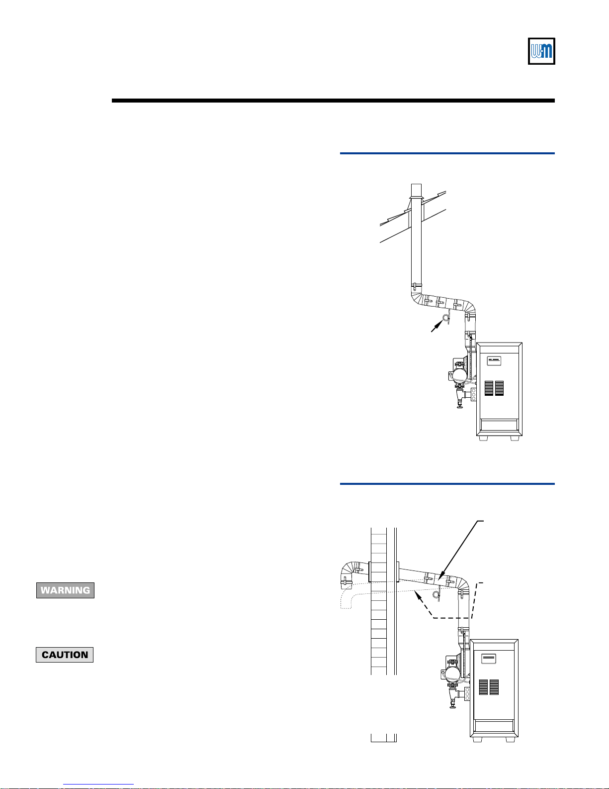
Horizontal drain tee.
Follow vent
manufacturer's
instructions to install
condensate drain line.
Follow vent
manufacturer's
instructions for proper
installation of vent runs,
including slope and
support.
3f
Venting —
direct exhaust............................
1. Do not mix types or manufacturers of vent materials.
2. Clean all joints before sealing. See vent manufacturer’s instructions for
cleaning and sealing joints. Use their specified sealant. Do not use screws.
3. Install vent pipe with seams on top of vent horizontal runs. Follow
requirements in section
3e, page 17, for vent termination.
4. Maintain minimum 2" clearance from combustible materials to vent
pipe.
Vertical venting — See Figure13. Follow vent manufacturer’s
5.
instructions for venting through roof.
• Vent pipe must extend through roof flashing, jacket or thimble.
• Vent may pass through floor, inside wall or concealed space when
installed according to vent manufacturer’s instructions.
Sidewall venting — See Figures 14 and 15. Vent must terminate at
least one foot above anticipated snowline. Vent must be terminated
only with:
• Tee or elbow with integral screen. (Tee may be mounted either
vertically or horizontally. DO NOT use horizontal tee with CGi-7
or CGi-8.)
• Elbow and termination coupling with screen (not available for
StaR-34).
Figure 13 Direct exhaust vertical venting
6. Do not seal vent pipe (slip connector for Saf-T Vent) to inside or outside
plate.
7. If passing through noncombustible wall, provide hole diameter large
enough to insert the vent pipe (slip connector for Saf-T Vent).
8. Install horizontal drain tee as close as possible to boiler, in first
horizontal run. See Figure 13.
9. Do not exceed the maximum vent system length given in
page 15.
Using any other material could cause flue gas leakage, potentially
resulting in severe personal injury, death or substantial property
damage.
• Vent manufacturer shows this option in their instructions.
• Vent is sloped toward termination as shown in dotted lines in
14
.
• The vent is installed per Weil-McLain and vent manufacturer’s
instructions.
Condensate drippage from such vents may accumulate on the ground
below. Consider traffic in the area to avoid hazard due to ice accumulation.
Condensate drain line — use only silicone tubing
rated for at least 400 °F for the condensate drain line.
Table 4,
On some installations, the condensate drain fitting
may be omitted, provided:
Figure
Figure 14 Direct exhaust sidewall venting
Horizontal drain tee.
Follow vent
manufacturer's
instructions to install
condensate drain line.
Optional downward
slope without drain
fitting, where allowed
by vent manufacturer
as explained in
CAUTION at left.
MODEL
CGi
Follow vent
manufacturer's instructions for
proper installation of vent runs,
including slope, support and
condensate drainage.
71016
18
Part Number 550-110-710/0200
Page 19

Boiler Manual
vertical or sidewall
Figure 15 Sidewall termination
Termination elbow or tee
®
Sealant
Saf-T Vent
Note 1
Termination elbow or tee
Sealant
Z-Vent II
Elbow and termination
coupling with screen
Sealant
Elbow and termination
coupling with screen
Sealant
Using any termination other than one of those shown
could cause nuisance outages and loss of heat, resulting
in substantial property damage.
Pipe
Band
clamp
Pipe section
section
Sealant
Metal
plate
Sealant
Exterior
Metal
plate
18" Slip
connector
Note 1: DO NOT use horizontal tee with CGi-7 or CGi-8.
Sealant
Pipe
section
Metal
plate
wall
Exterior
wall
Metal
plate
StaR-34
™
FasNSeal
Termination elbow or tee
Sealant
Sealant
Termination elbow or tee
Note 1
Note 1
Note 1
Termination coupling
not available
Elbow and termination
coupling with screen
Locking
band
Note 1: DO NOT use horizontal tee with CGi-7 or CGi-8.
Metal
plate
Sealant
Exterior
Metal
plate
Pipe
section
Note 1: DO NOT use horizontal tee with CGi-7 or CGi-8.
Note 1: DO NOT use horizontal tee with CGi-7 or CGi-8.
Pipe
section
Metal
plate
wall
Exterior
wall
Metal
plate
Pipe section
Pipe
section
71017
Part Number 550-110-710/0200
19
Page 20

GOLD CGi Series 2 Gas-Fired Water Boiler
4a
Water piping —
general information
General piping information
If installation is to comply with ASME or Canadian requirements, an
additional high temperature limit is needed. Install control in supply
piping between boiler and isolation valve. Set second control to minimum
20 °F above setpoint of first control. Maximum allowable setpoint is 240 °F.
See section 9b, pages 38 and 39, for wiring.
A low water cutoff device is required when boiler is installed above
radiation level or by certain state or local codes or insurance companies.
Use low water cutoff designed for water installations. Electrode probetype is recommended. Purchase and install in tee in supply piping above
boiler.
Use backflow check valve in cold water supply as required by local codes.
Pressure/temperature gauge
Install pressure/temperature gauge in tee on supply piping (as shown in
drawing on page 3). The gauge well is a self-closing valve, allowing removal
of the gauge without draining the system.
Slowly remove pressure/temperature gauge from well.
The self-closing valve could leak if clogged with
sediment. If water begins to spray, stop removing gauge.
Close system fill valve and drain enough water to release
system pressure before continuing with gauge removal.
Escaping hot water could cause severe personal injury.
Circulator
The circulator is shipped loose (wiring pre-attached
to boiler) to allow you to locate it either in the return
or supply piping, as desired. See page 3 for a typical
installation. Pipe the expansion tank to the suction side
of the circulator whenever possible. Install an air
separator in the supply piping. Connect the expansion
tank to the air separator only if the separator is on the
suction side of the circulator. Always install the system
fill connection at the same point as the expansion tank
connection to the system. Figures 16 and 17 show
typical near-boiler piping connections.
System water piping
See Figure 16 (diaphragm-type or bladder-type
expansion tank) or Figure 17 (closed-type expansion
tank) on page 21, and
and single-zone systems designed for return water at
least 130 °F.
See pages 22-23 to complete multiple-zone piping or
pages 24-29 to complete piping for radiant heating
systems or converted gravity systems.
Refer to page 29 for boilers used with refrigeration systems.
Table 6 below, for near-boiler
Relief valve
Install relief valve vertically in ¾" tapping on side of boiler. See Figure 16
and the tag attached to the relief valve for manufacturer’s instructions.
or 17
To avoid water damage or scalding due to relief valve
operation:
• Discharge line must be connected to relief valve outlet and
safe place of disposal
possibility of severe burns should the valve discharge.
• Discharge line must be as short as possible and be the
the valve discharge connection
• Discharge line must pitch downward from the valve and terminate at
least 6" above the floor drain where any discharge will be clearly visible.
• The discharge line shall terminate plain, not threaded, with a material
serviceable for temperatures of 375 °F or greater.
Do not pipe the discharge to any place where freezing could occur.
•
• No shutoff valve shall be installed between the relief valve and boiler,
or in the discharge line. Do not plug or place any obstruction in the
discharge line.
•
Failure to comply with the above guidelines could result in failure of
the relief valve to operate, resulting in possibility of severe personal
injury, death or substantial property damage.
• Test the operation of the valve after filling and pressurizing system
by lifting the lever. Make sure the valve discharges freely. If the valve
fails to operate correctly, replace it with a new relief valve.
. Terminate the discharge line to eliminate
throughout its entire length.
run to a
same size as
Table 6 Water pipe size (based on 20 °F rise)
Boiler
model number
CGi-25 ¾" ¾"
CGi-3 1" 1"
CGi-4 1" 1"
CGi-5 1" 1"
CGi-6 1¼" 1¼"
CGi-7 1¼" 1¼"
CGi-8 1½" 1½"
Note: Circulator flange supplied with boiler is same size as
recommended piping above.
• Chilled medium, if used, is piped in parallel with
heating boiler. Use appropriate valves to prevent
chilled medium from entering boiler. Consult
I=B=R Installation and Piping Guides.
• If boiler is connected to heating coils located in air
handling units where they can be exposed to
refrigerated air, use flow control valves or other
automatic means to prevent gravity circulation
during cooling cycle. Circulation of cold water
through the boiler could result in damage to the
heat exchanger, causing possible severe personal
injury, death or substantial property damage.
To
system
Install boiler such that —
From
system
20
Part Number 550-110-710/0200
Page 21
Boiler Manual
M
O
DE
L
CGi
71019
To system
From
system
Isolation
valve
Drain
valve
Relief
valve
Circulator*
Isolation
valve
Circulator
Cold water fill
CLOSED type
expansion tank
*Alternate
location
Water piping — single-zone system4b
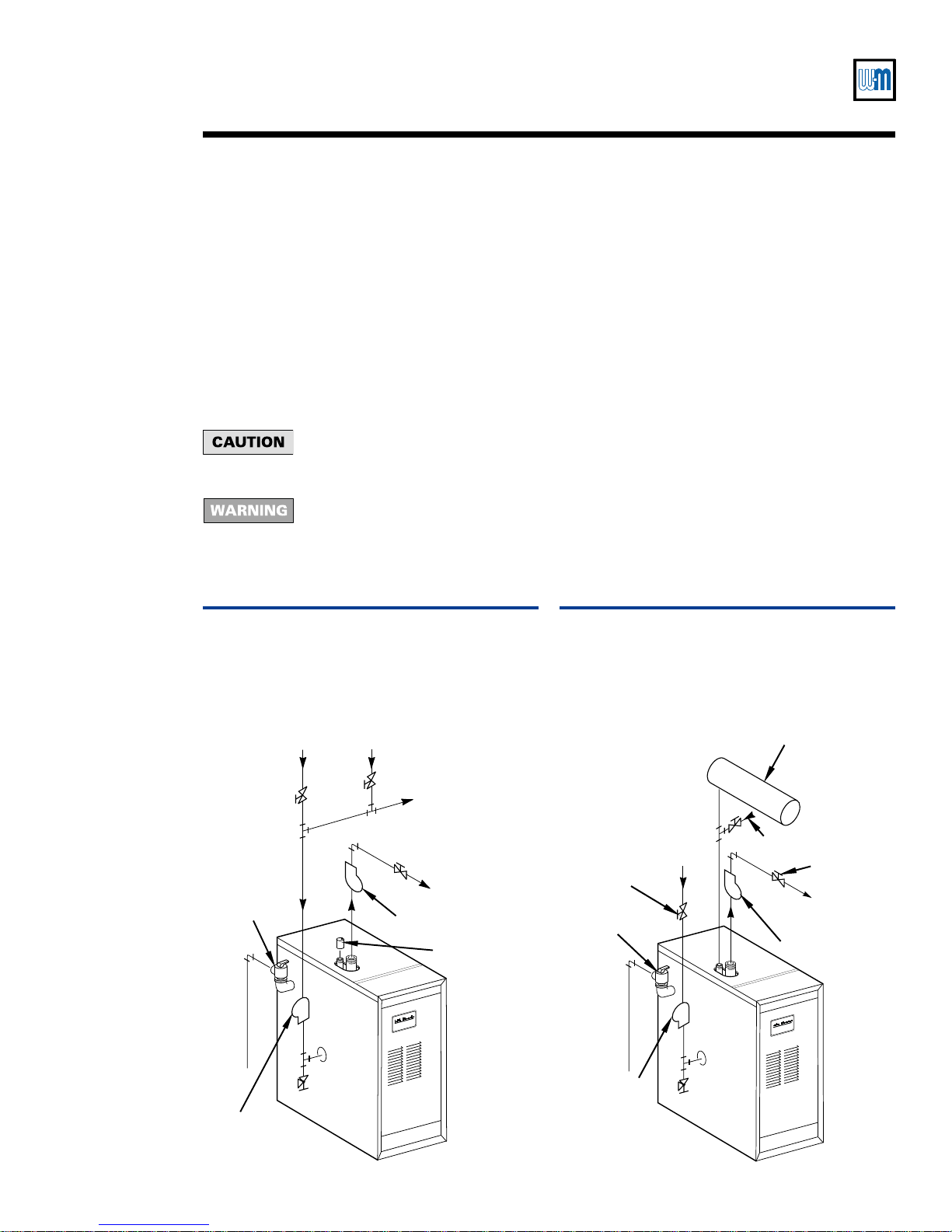
Expansion tank
Diaphragm-type or bladder-type
expansion tank — Figure 16
1. Ensure expansion tank size will handle boiler and
system water volume and temperature. Tank must
be located in boiler return piping as close to boiler
as possible, before inlet side of circulator. See tank
manufacturer’s instructions for details.
2. Install an automatic air vent as shown.
Undersized expansion tanks cause system water to be lost from relief valve and makeup water
to be added through fill valve. Eventual section failure can result.
Use Figure 16 or Figure 17 only for single-zone systems designed for return water at least
130 °F. For systems with low return water temperature possible, such as converted gravity
systems and radiant heating systems, refer to the special piping suggestions of pages 24-29.
Failure to prevent low return water temperature to the boiler could cause corrosion of the
boiler sections or burners, resulting in severe personal injury, death or substantial property
damage.
Figure 16 Diaphragm- or bladder-type expansion tank
Piping to single-zone system using
diaphragm-type or bladder-type expansion
tank. See Table 6 for piping sizes.
Cold
From
system
water
fill
Closed-type expansion tank —
Figure 17
1. Ensure expansion tank size will handle boiler and
system water volume and temperature. See tank
manufacturer’s instructions for details.
2. Connect tank to ½" NPT tapping located behind
supply outlet, using ½" NPT piping. Pitch any
horizontal piping up towards tank 1 inch per 5 feet
of piping.
Figure 17 Closed-type expansion tank
Piping to single-zone system using closedtype expansion tank. See Table 6 for piping
sizes.
Isolation
valve
Relief
valve
Circulator
Part Number 550-110-710/0200
Drain
valve
To DIAPHRAGM
expansion tank
and fittings
Isolation
valve
To system
Circulator*
Automatic
EL
D
O
M
CGi
71018
air vent
*Alternate
location
21
Page 22

GOLD CGi Series 2 Gas-Fired Water Boiler
Water piping — multiple zones4c
Piping multiple
zones
Zoning with
circulators, return
temp over 130 °F
Zoning with zone
valves, return temp
over 130 °F
Piping for radiant
heating systems or
converted gravity
systems
Follow instructions on pages 20 and 21 to install near-boiler or single-zone piping. (Also
refer to
applicable.)
See
1. Size each circulator to individual circuit requirements.
2. Do not install circulator on boiler (except for primary/secondary piping).
3. Install isolation (balancing) valves to adjust flow to distribute heat to all zones.
4. Install and wire a separate relay for each zone circulator.
1. Install isolation (balancing) valves to adjust flow to distribute heat to all zones.
2. Provide a separate 24-volt transformer to power the zone valves. Size the transformer to
Converted gravity (or steam) systems
Whenever possible, use the primary/secondary piping shown in Figures 20 or 21 on page 25.
This piping design allows changing boiler flow rate without affecting primary circuit flow
rate.
If
23
the reduced flow rate in the heating system will not cause heat distribution problems.
Piping for radiant heating systems or converted gravity systems, below, if
Figure 18 or Figure 19 to complete installation.
handle the total rated load of all connected zone valves.
Figures 20 or 21 cannot be used, use the boiler-bypass piping shown in Figure 22 or Figure
on page 27. You can also use the piping shown in Figure 24 on page 29 (system-bypass), if
Failure to prevent low return water temperature to the boiler could cause corrosion of the
boiler sections or burners, resulting in severe personal injury, death or substantial property
damage.
Radiant heating systems
Preferably, use primary/secondary piping, as shown in Figures 20 or 21 on page 25.
Alternatively, use the method of either Figure 22 or Figure 23 on page 27. Do not use the
piping of Figure 24
supply temperature.
If radiant system tubing has no oxygen barrier, a
Radiant heating system piping should include a means of regulating the boiler return water
temperature and the system supply temperature (such as provided by an injection pumping
control). Boiler return water temperature will be adequately controlled using the methods
shown in this manual provided the system supply temperature is relatively constant.
Do not apply the methods in this manual if the system is equipped with an outdoor reset
control
temperature at no less than 130 °F regardless of system supply temperature. Contact your
Weil-McLain representative for suggested piping and control methods. Failure to prevent
cold return water temperature to the boiler could cause corrosion damage to the sections or
burners, resulting in possible severe personal injury, death or substantial property damage.
22
(system-bypass), because this method does not control radiant system
heat exchanger must be used.
. Instead, provide controls and piping which can regulate the boiler return water
Part Number 550-110-710/0200
Page 23
Boiler Manual
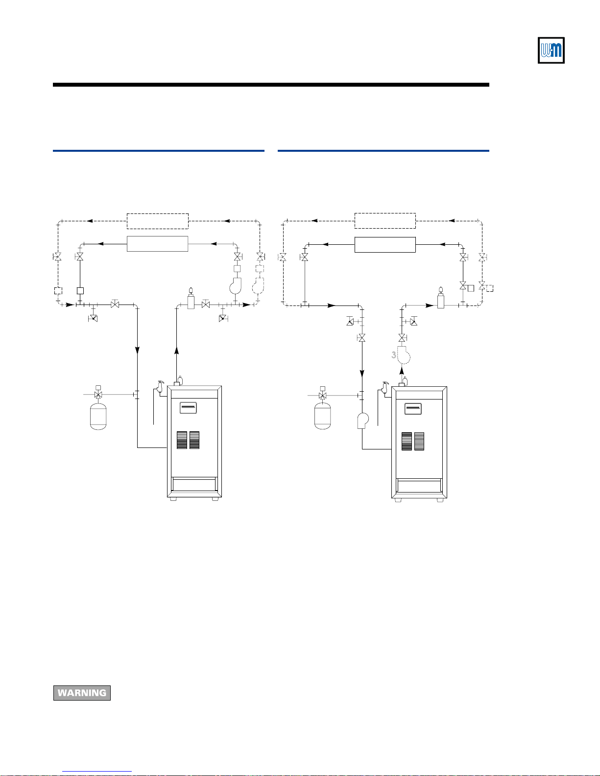
typical piping — multiple-zone installations
Figure 18
Zoning with circulators
— return water 130 °F or higher.
ZONE 2
ZONE 1
1
2
11
13
10
CGi
Cold
water
6
9
11
fill
12
Figure 19
Zoning with zone valves
— return water 130 °F or higher.
ZONE 2
ZONE 1
1
1
1
2
3
6
6
6
5
13
11
Alternate
circulator
location
Cold
water
MODEL
11
fill
12
9
10
MODEL
CGi
1 Boiler isolation (balancing) valves
2 Flow/check valve
3 System or zone circulator
5 Zone valve
6 Drain valve
9 Relief valve
10 Automatic air vent (with diaphragm-type
expansion tank), or connect to tank fitting (closedtype expansion tank).
DO NOT use an automatic
For systems with possible low return-water temperature (such as converted gravity systems,
radiant heating systems and heat pump systems), refer to the special piping suggestions of
Figures 20 - 24, as applies. Failure to prevent sustained low return water temperature to the
boiler could cause corrosion of the boiler sections, resulting in severe personal injury, death
or substantial property damage.
Part Number 550-110-710/0200
71020
71021
air vent when using closed-type expansion tank. It
would allow air to leave the system, causing
waterlogging of the expansion tank.
11 Fill valve
12 Diaphragm-type or bladder-type expansion tank,
if used (For closed-type expansion tank, pipe from
top of air separator to tank fitting as in Figure 17.)
13 Air separator and automatic vent, if used (Note that
the fill valve must always be connected to the
expansion tank, regardless of location of expansion
tank circulator or air separator.
23
Page 24
GOLD CGi Series 2 Gas-Fired Water Boiler
Water piping — low temp systems4d
Primary/secondary
(preferred) bypass
piping method
Temperature
gauges
Valve adjustment
(Figure 20 and 21 only)
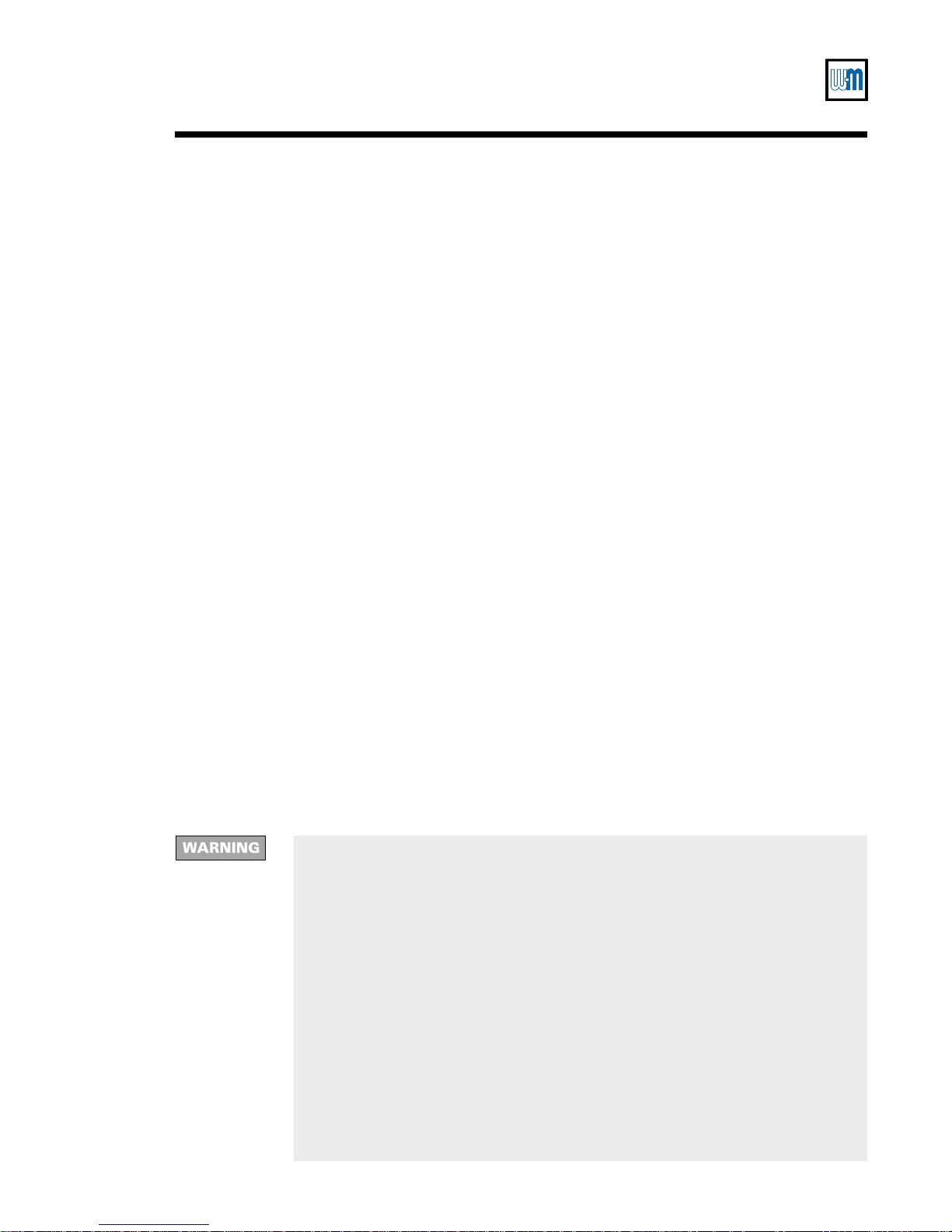
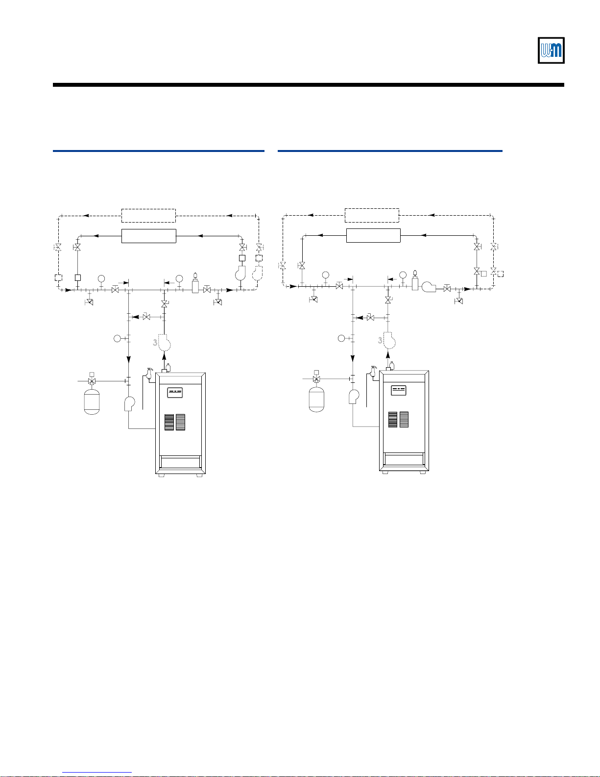
Primary/secondary bypass piping is preferred because the flow rate and temperature drop in
the heating circuit(s) is determined only by the heating circuit circulator(s). So adjustment
of the bypass valves in the boiler circuit will not cause a change in the heating circuit rate and
temperature distribution.
Figures 20 and 21 show suggested bypass arrangements using primary/secondary bypass
piping (preferred) for low temperature systems such as radiant heating systems or converted
gravity systems
The bypass valves (items
system return water — set to assure a minimum return water temperature (at least 130 °F) to
the boiler. Set the valves as explained below.
Gauge 4a is suggested, but optional on any system.
4b is optional on converted gravity systems, but required on radiant heating systems
Gauge
— to display the water temperature being supplied to the radiant tubing.
Gauge
8 is required on all systems to assure the return water temperature is accurately set for
a minimum of 130 °F. If this gauge is not available however, adjust the valves such that the
boiler-mounted temperature/pressure gauge reads at least 150 °F when the system return
water is cold (approximately 60 °F water temperature).
1. Set the valves while the system is cool, setting for the coldest expected water temperature
(usually 60 °F since the system will often drop to room temperature between cycles).
2. Start with valve 7a fully closed and 7b fully open.
3. Gradually open valve 7a while closing valve 7b until the temperature at gauge 8 reads
130 °F when gauge 4a reads 60 °F.
4. Note that valve
with return water. Valve 7b regulates the amount of system water flowing through the
boiler secondary loop.
. For alternatives, see pages 26 through 29.
7a and 7b) provide mixing of hot boiler outlet water with cooler
7a regulates the amount of hot water from the boiler supply which mixes
Failure to prevent low return water temperature to the boiler could cause corrosion of
the boiler sections or burners, resulting in severe personal injury, death or substantial property
damage.
Radiant heating system piping should include a means of regulating the boiler return
water temperature
pumping control
Boiler return water temperature will be adequately controlled using the methods shown in
this manual provided the
DO NOT apply the methods of this manual if the system is equipped with an outdoor
reset control
water temperature
your Weil-McLain representative for suggested piping and control methods.
Failure to prevent cold return water temperature to the boiler could cause corrosion
damage to the sections or burners, resulting in possible severe personal injury, death or
substantial property damage.
24
and the system supply temperature (such as provided by an injection
).
system supply temperature is relatively constant.
. Instead, provide controls and piping which can regulate the boiler return
at no less than 130 °F regardless of system supply temperature. Contact
Part Number 550-110-710/0200
Page 25
Boiler Manual
primary/secondary (preferred) bypass piping —
for radiant heating or converted gravity systems
Figure 20
Zoning with circulators
ZONE 2
ZONE 1
1
Cold
water
4a 4b
2
66
8
11
fill
12
12"
MAX.
1
7a
9
7b
Alternate
circulator
location
10
MODEL
CGi
13
Figure 21
Zoning with zone valves
ZONE 2
ZONE 1
1
2
3
1
Cold
water
1
4a 4b
66
8
11
fill
12
12"
MAX.
1
7a
9
7b
Alternate
circulator
location
10
3
13
MODEL
CGi
1
5
1
71022
1 Boiler isolation (balancing) valves
2 Flow/check valve
3 System or zone circulator
4 System temperature gauges
5 Zone valve
6 Drain valve
7 System temperature valves (see instructions to the
left for adjusting valves)
8 Blend temperature gauge
9 Relief valve
71023
10 Automatic air vent (with diaphragm-type expansion
tank), or connect to tank fitting (closed-type expansion
tank). DO NOT use an automatic air vent when using
closed-type expansion tank. It would allow air to leave
the system, causing waterlogging of the expansion tank.
11 Fill valve
12 Diaphragm-type or bladder-type expansion tank, if
used (For closed-type expansion tank, pipe from top
of air separator to tank fitting as in Figure 17.)
13 Air separator and automatic vent, if used (Note that
the fill valve must always be connected to the expansion
tank, regardless of location of expansion tank,
circulator or air separator.)
Part Number 550-110-710/0200
25
Page 26
GOLD CGi Series 2 Gas-Fired Water Boiler
Water piping — low temp systems4e
Boiler-bypass
piping method
Temperature
gauges
Valve adjustment
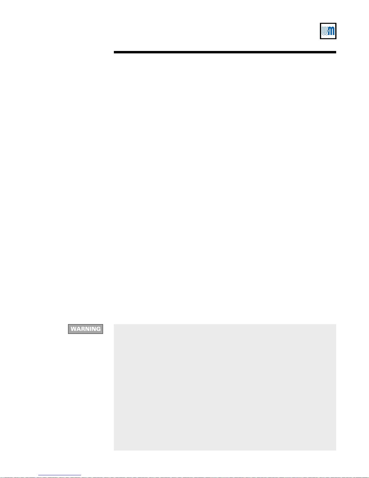
This piping method is called a boiler-bypass because part of the circulator flow is bypassed
around the boiler (through valve 7a). This method reduces the flow rate throughout the
boiler, in order to raise the average water temperature in the boiler enough to prevent flue gas
condensation. Boiler-bypass piping is effective for some boilers — including the CGi —
provided the flow rates are adjusted according to the instructions following.
Figures 22 and 23 are alternative piping suggestions for converted gravity (large water content
or steam systems) or radiant heating system — for use when primary/secondary piping
can’t be applied. (Figure 24 is another alternative, using system bypass in place of boilerbypass piping. Figure 24 however, is not suitable for radiant heating applications because it
does not protect the radiant system from possible high water temperature.)
Boiler-bypass piping keeps system flow rate as high as possible and temperature drop as low
as possible, helping to equalize the building heat distribution.
Gauge 4a is optional if the bypass valves will be adjusted using cold (or room temperature)
return water to the boiler. (When setting the valves without gauge 4a installed — using cold
or room temperature water — assume the return water temperature to be 60 °F. Set the valves
so gauge 8 reads at least 120 °F.
4b is optional on converted gravity systems, but required on radiant heating systems
Gauge
— to display the water temperature being supplied to the radiant tubing.
Gauge
8 is required on all systems to assure reliable adjustment of the bypass valves. The
boiler-mounted temperature/pressure gauge can be used if a separate temperature gauge is
not installed.
1. Start with valve 7a fully closed and 7b fully open.
2. Gradually open valve
60 °F higher than gauge 4a. A minimum 60 °F temperature rise through the boiler assures
a low enough flow rate and high enough average temperature to prevent condensation
even with low system return water temperature.
3. Valve 7a regulates the system flow rate, while valve 7b regulates the boiler flow rate.
4. The boiler-mounted temperature/pressure gauge may be used in place of a separate
gauge 8.
7a while closing valve 7b until the temperature at gauge 8 reads
Failure to prevent low return water temperature to the boiler could cause corrosion of
the boiler sections or burners, resulting in severe personal injury, death or substantial property
damage.
Radiant heating system piping should include a means of regulating the boiler return
water temperature
pumping control
Boiler return water temperature will be adequately controlled using the methods shown in
this manual provided the
DO NOT apply the methods of this manual if the system is equipped with an outdoor
reset control
water temperature
your Weil-McLain representative for suggested piping and control methods.
Failure to prevent cold return water temperature to the boiler could cause corrosion
damage to the sections or burners, resulting in possible severe personal injury, death or
substantial property damage.
26
and the system supply temperature (such as provided by an injection
).
system supply temperature is relatively constant.
. Instead, provide controls and piping which can regulate the boiler return
at no less than 130 °F regardless of system supply temperature. Contact
Part Number 550-110-710/0200
Page 27
Boiler Manual
boiler-bypass (alternate) piping —
for radiant heating or converted gravity systems
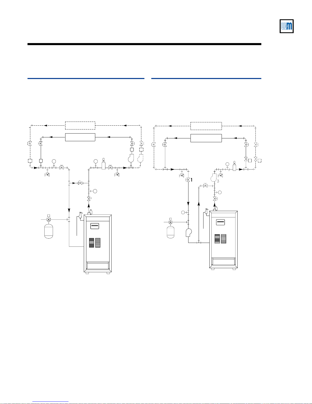
Figure 22 Boiler-bypass piping
Zoning with circulators
(Alternative to primary/secondary piping
Figures 20 and 21)
ZONE 2
ZONE 1
1
4a 4b
2
11
66
7a
13
8
7b
Cold
water
11
9
fill
12
10
MODEL
CGi
Figure 23 Boiler-bypass piping
Zoning with zone valves
(Alternative to primary/secondary piping
Figures 20 and 21)
ZONE 2
ZONE 1
1
11
2
3
Alternate
circulator
location
7a
9
7b
Cold
water
6
4a
11
fill
12
3
10
4b
6
8
MODEL
CGi
5
13
1 Boiler isolation (balancing) valves
2 Flow/check valve
3 System or zone circulator
4 System temperature gauges
5 Zone valve
6 Drain valve
7 System temperature valves (see instructions to the left
for adjusting valves)
8 Blend temperature gauge
9 Relief valve
Part Number 550-110-710/0200
71024
71025
10 Automatic air vent (with diaphragm-type
expansion tank), or connect to tank fitting (closedtype expansion tank). DO NOT use an automatic
air vent when using closed-type expansion tank. It
would allow air to leave the system, causing
waterlogging of the expansion tank.
11 Fill valve
12 Diaphragm-type or bladder-type expansion tank,
if used (For closed-type expansion tank, pipe from
top of air separator to tank fitting as in
Figure 17,
page 21).
13 Air separator and automatic vent, if used (Note that
the fill valve must always be connected to the
expansion tank, regardless of location of expansion
tank, circulator or air separator.)
27
Page 28
GOLD CGi Series 2 Gas-Fired Water Boiler
Water piping — low temp systems4f
System-bypass
piping method
Valve adjustment
This piping method is called a system-bypass because part of the circulator flow bypasses
the system (through valve
cooler system return water temperature in order to provide minimum 130 °F return water to
the boiler. Valve 7b will most often be full open, but may need to be slightly closed on some
low pressure drop systems in order to cause enough flow through valve
Figure 24 is an alternative piping method that provides return water temperature control for
boilers installed on
Do not apply the piping of Figure 24 on radiant heating systems. It provides no method
regulating the water temperature provided to the system and could result in excessive water
temperature in the radiant tubing.
System-bypass piping as shown in
zoning. When used with circulator zoning however, the boiler circulator (item 3), must be
piped as shown. It cannot be used as one of the zoning circulators.
Do not apply system-bypass piping if the reduced flow in the system could cause poor heat
distribution. That is, system-bypass piping reduces the flow in the system and increases the
water temperature supplied to the system. This can cause increased heat from radiators at the
beginning of the system and reduced heat from radiators near the end of the system.
1. Start with valve 7a fully closed and 7b fully open.
2. Gradually open valve
least 130 °F at all times.
converted gravity systems (large water content or steam systems).
7a). This bypassed hot water from the boiler outlet mixes with
7a.
Figure 24 can be used with either zone valve or circulator
7a while closing valve 7b until the temperature at gauge 8 reads at
3. Valve 7a regulates the amount of boiler supply water mixed with return water. Valve 7b
causes a pressure drop in the system needed to balance flow through valve 7a and the
system.
4. The valve adjustment should be done with the system at the coldest expected temperature
(60 °F for converted gravity systems or high mass radiant systems).
Failure to prevent low return water temperature to the boiler could cause corrosion of
the boiler sections or burners, resulting in severe personal injury, death or substantial property
damage.
Radiant heating system piping should include a means of regulating the boiler return
water temperature
pumping control
Boiler return water temperature will be adequately controlled using the methods shown in
this manual provided the
DO NOT apply the methods of this manual if the system is equipped with an outdoor
reset control
water temperature
your Weil-McLain representative for suggested piping and control methods.
Failure to prevent cold return water temperature to the boiler could cause corrosion
damage to the sections or burners, resulting in possible severe personal injury, death or
substantial property damage.
and the system supply temperature (such as provided by an injection
).
system supply temperature is relatively constant.
. Instead, provide controls and piping which can regulate the boiler return
at no less than 130 °F regardless of system supply temperature. Contact
28
Part Number 550-110-710/0200
Page 29
Boiler Manual
4f
system-bypass (alternate) piping —
for converted gravity (or steam) systems
Cold
water
fill
11
12
To systemFrom system
7a
7b
Alternate
circulator
location
8
9
10
MODEL
CGi
3
71026
Figure 24 System-bypass piping
Zoning with zone valve or circulators, return
water 130 °F or higher.
(Alternative to boiler-bypass piping
Figures 22 and 23)
3 System or zone circulator
7 System temperature valves (see instructions to the left for
adjusting valves)
8 Blend temperature gauge
9 Relief valve
10 Automatic air vent (with diaphragm-type expansion
tank), or connect to tank fitting (closed-type expansion
tank). DO NOT use an automatic air vent when using
closed-type expansion tank. It would allow air to leave
the system, causing waterlogging of the expansion tank.
11 Fill valve
12 Diaphragm-type or bladder-type expansion tank, if used
(For closed-type expansion tank, pipe from top of air
separator to tank fitting as in Figure 17.)
Water piping — refrigeration system4g
Figure 25 Piping refrigeration systems
System
supply
Circulator
System
return
71027
Part Number 550-110-710/0200
Water
chiller
Strainer
Check
valve
Balancing
valve
Expansion tank
Shut-off
valve
Boiler
Prevent chilled water from
entering boiler
Install boiler so that chilled
medium is piped in parallel with
the heating boiler. Use appropriate
valves to prevent chilled medium
from entering boiler. See
for typical installation of balancing
valve and check valve.
If boiler is connected to heating
MODEL
CGi
coils located in air handling units
where they can be exposed to
refrigerated air, use flow control
valves or other automatic means to
prevent gravity circulation during
cooling cycle.
Figure 25
29
Page 30
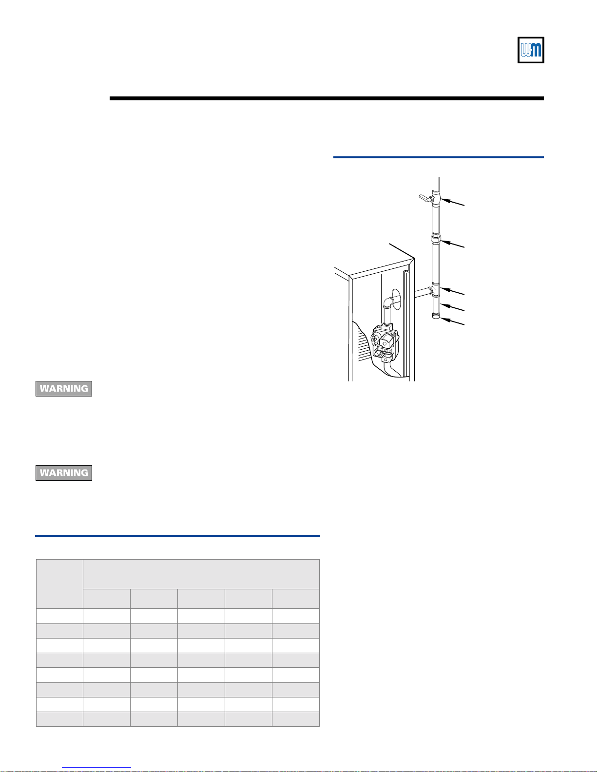
GOLD CGi Series 2 Gas-Fired Water Boiler
Gas piping5
Connecting gas supply piping to boiler
1. Remove jacket front panel and refer to
a. Install drip leg at inlet of gas connection to boiler. Where local
utility requires drip leg to be extended to the floor, use appropriate
length of pipe between cap and tee.
b. Install ground joint union for servicing, when required.
c. Install manual shutoff valve in gas supply piping outside boiler
jacket when required by local codes or utility requirements.
d. In Canada — When using manual main shutoff valve, it must be
identified
by the installer.
2. Support piping with hangers, not by boiler or its accessories.
3. Purge all air from gas supply piping.
4. Before placing boiler in operation,
for leaks
a.
.
Close manual main shutoff valve during any pressure testing at
less than 13" w.c.
Disconnect boiler and gas valve from gas supply piping during
b.
any pressure testing greater than 13" w.c.
Do not check for gas leaks with an open flame —
use bubble test. Failure to use bubble test or check for
gas leaks can cause severe personal injury, death or
substantial property damage.
5. Use pipe dope compatible with propane gases. Apply sparingly only
to male threads of pipe joints so that pipe dope does not block gas
flow.
Failure to apply pipe dope as detailed above can result
in severe personal injury, death or substantial property
damage.
Figure 26 to pipe gas to boiler.
check boiler and its gas connection
Figure 26 Gas supply piping
Manual main
shutoff gas valve
(when required)
Ground joint union
(when required)
Tee
Nipple
Cap
71028
Natural Gas:
1. Refer to Table 7 for pipe length and diameter. Base
on rated boiler input (divide by 1,000 to obtain
cubic feet per hour). Table 7 is only for gas with
specific gravity 0.60, with a pressure drop
through the gas piping of 0.30" w.c.
gas pipe sizing information, refer to ANSI Z223.1
(or B149.1 or B149.2 for Canadian installations).
For additional
Table 7 Pipe capacity for 0.60 specific gravity natural gas
Gas pipe
length
(feet)
10 132 278 520 1050 1600
20 92 190 350 730 1100
30 73 152 285 590 860
40 63 130 245 500 760
50 56 115 215 440 670
75 45 93 175 360 545
100 38 79 150 305 460
150 31 64 120 250 380
Capacity of pipe for pipe size of:
(Capacity in cubic feet gas per hour)
½" ¾" 1" 1¼" 1½"
30
2. Inlet pressure required at gas valve inlet:
• Maximum: 13" w.c.
• Minimum: 5" w.c.
• Manifold gas pressure: 3.5" w.c.
3. Install 100% lockup gas pressure regulator in
supply line
if inlet pressure exceeds 13" w.c.
Adjust for 13" w.c. maximum.
Propane Gas:
1. Contact gas supplier to size pipes, tanks and 100%
lockup gas pressure regulator.
2. Adjust propane supply regulator provided by gas
supplier for 13" w.c. maximum pressure.
3. Inlet pressure required at gas valve inlet:
• Maximum: 13" w.c.
• Minimum: 11" w.c.
• Manifold gas pressure: 10" w.c.
Part Number 550-110-710/0200
Page 31
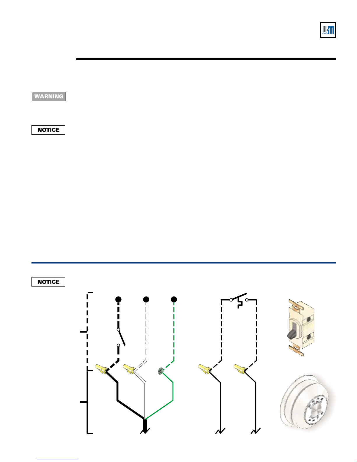
Boiler Manual
Field wiring6
For your safety, turn off electrical power supply at
service entrance panel before making any electrical
connections
to avoid possible electric shock hazard.
Failure to do so can cause severe personal injury or
death.
Wiring must be N.E.C. Class 1.
If original rollout thermal fuse element wire as supplied
with boiler must be replaced, use only type 200 °C wire
or equivalent. If other original wiring as supplied with
boiler must be replaced, type 105 °C wire or equivalent
must be used.
Boiler must be
electrically grounded as required by
National Electrical Code ANSI/NFPA 70–latest edition.
Electrical installation must
comply with:
1. National Electrical Code and any other national,
state, provincial or local codes or regulations.
2. In Canada, CSA C22.1 Canadian Electrical Code
Part 1, and any local codes.
Wiring connections
Boiler is shipped with controls completely wired.
Thermostat
1. Connect thermostat as shown on wiring diagram
on boiler.
2.
Install on inside wall away from influences of
drafts, hot or cold water pipes, lighting fixtures,
television, sunrays, or fireplaces.
3. If thermostat has a heat anticipator, set heat
anticipator in thermostat to match power
requirements of equipment connected to it. If
connected directly to boiler, set for 0.1 amps plus
gas valve current. See information on wiring
diagram as shown in
Figure 32, page 39. For other
devices, refer to manufacturer’s specifications.
Wiring diagram on boiler gives setting for control
module and gas valve. Also see instructions with
thermostat.
Junction Box (furnished)
1. Connect 120 VAC power wiring as shown in
Figure 27.
2. Fused disconnect or service switch (15 amp.
recommended) may be mounted on this box. For
those installations with local codes which prohibit
installation of fused disconnect or service switch
on boiler, install a 2 x 4 cover plate on the boiler
junction box and mount the service switch
remotely as required by the code.
Figure 27 Field wiring connections — service switch and thermostat (or end switch) provided by installer
The CGi control module is polarity-sensitive. The hot and neutral wires must be connected to the correct leads.
A flashing POWER light usually indicates reversed polarity of 120 VAC lead wires.
Service
switch
(not provided)
Field wiring
Factory wiring
120 VAC
Hot Neutral
Black White Green
Junction box,
boiler left side
Ground
Thermostat
or end switch
(not provided)
Ground screw Wire nuts
Black Black
Thermostat
leads, through
jacket left side
71029
or end switch
Service
switch
(not provided)
Thermostat
(not provided)
Part Number 550-110-710/0200
31
Page 32
GOLD CGi Series 2 Gas-Fired Water Boiler
Start-up — preparation7a
Check for gas leaks
Propane boilers only — Your propane supplier mixes an odorant with the propane to make
its presence detectable. In some instances, the odorant can fade and the gas may no longer
have an odor.
• Propane gas can accumulate at floor level. Smell near the floor for the gas odorant or any
unusual odor. If you suspect a leak, do not attempt to light the pilot.
• Use caution when attempting to light the propane pilot. This should be done by a qualified
service technician, particularly if pilot outages are common.
• Periodically check the odorant level of your gas.
• Inspect boiler and system at least yearly to make sure all gas piping is leak-tight.
• Consult your propane supplier regarding installation of a gas leak detector. There are
some products on the market intended for this purpose. Your supplier may be able to
suggest an appropriate device.
Before starting the boiler, and during initial operation, smell near the floor and around the
boiler for gas odorant or any unusual odor. Do not proceed with start-up if there is any
indication of a gas leak. Repair any leak at once.
Determine if water treatment is needed
Do not use petroleum-based
cleaning or sealing compounds
boiler system. Severe damage to
boiler will occur, resulting in
substantial property damage.
Verify water chemistry
Consult local water treatment companies for unusually
hard water areas (above 7 grains hardness) or low pH
water conditions (below 7.0). Boiler water pH of 7.0
to 8.5 is recommended.
Freeze protection (when used)
Use antifreeze made especially for hydronic systems.
Inhibited propylene glycol is recommended.
in
water content. Boiler water content is listed on
page 63. Remember to include expansion tank
water content.
2. Follow antifreeze manufacturer's instructions.
3. A 50% solution of propylene glycol/water provides
maximum protection to about -30 °F.
4. Local codes may require back flow preventer or
actual disconnect from city water supply.
Eliminate all system leaks.
Continual fresh makeup water will
reduce boiler life. Minerals can
build up in sections, reducing heat
transfer, overheating cast iron, and
causing section failure.
Do not use ethylene glycol,
automotive or undiluted
antifreeze
or death can result.
1. Determine antifreeze quantity according to system
32
. Severe personal injury
5. When using antifreeze in a system with automatic
fill, install a water meter to monitor water makeup.
Glycol will leak before the water begins to leak,
causing glycol level to drop. Added water will dilute
the antifreeze, reducing the freeze protection level.
Part Number 550-110-710/0200
Page 33
Boiler Manual
Fill the system with water
1. Close manual and automatic air vents and boiler
drain cock.
2. Fill to correct system pressure. Correct pressure
will vary with each application. Typical cold water
fill pressure for a residential system is 12 psi.
3. Purge air from system:
a. Connect a hose to the purge valve (see drain
valves, item
on pages 21 through 27, Figure 16 through
Figure 23). Route hose to an area where water
can drain and be seen.
b. Close the boiler or system isolation valve
between the purge valve and fill connection to
the system.
c. Close zone isolation valves.
d. Open quick-fill valve on cold water makeup
line.
e. Open purge valve.
f. One zone at a time, open the isolation valves.
Allow water to run through the zone, pushing
out the air. Run until no noticeable air flow is
present. Close the zone isolation valves and
proceed with the next zone. Follow this
6, in suggested piping diagrams
procedure until all zones are purged.
g. Close the quick-fill water valve and purge valve
and remove the hose. Open all isolation valves.
Watch that system pressure rises to correct
cold-fill pressure.
h. After the system has operated for a while,
eliminate any residual air by using the manual
air vents located throughout the system.
i. If purge valves are not installed in system, open
manual air vents in system one at a time,
beginning with lowest floor. Close vent when
water squirts out. Repeat with remaining vents.
4. Open
5. Open other vents:
6. Refill to correct pressure.
automatic air vent (diaphragm-type or
bladder-type expansion tank systems only) one
turn.
a. Starting on the lowest floor, open air vents one
at a time until water squirts out.
b. Repeat with remaining vents.
Inspect system water piping
After filling the boiler and system with water, inspect all piping throughout the system for leaks. If found, repair
immediately. Repeat this inspection after the boiler has been started and the system has heated up.
Leaks must be repaired at once. Failure to do so can damage the boiler, resulting in substantial
property damage.
Do not use petroleum-based cleaning or sealing compounds in boiler system. Severe damage
to boiler will occur, resulting in substantial property damage.
Inspect base insulation
Check to make sure insulation is secure against all four sides of the base. If insulation is damaged or displaced,
do not operate boiler. Replace or reposition insulation.
Failure to replace damaged insulation or reposition insulation can result in a fire hazard,
causing severe personal injury, death or substantial property damage.
The boiler contains ceramic fiber and fiberglass materials. Use care when handling these
materials per instructions on page 64 of this manual. Failure to comply could result in severe
personal injury.
Part Number 550-110-710/0200
33
Page 34
GOLD CGi Series 2 Gas-Fired Water Boiler
Start-up — operate boiler7b
Final check before starting boiler
• Read manual section 9, page 37, including the Operating instructions
procedure (Figure 33, page 40).
• Verify the boiler and system are full of water.
• Verify the
completed.
Start-up preparation procedures of section 7a have been
Start the boiler
• Follow the Operating instructions from section 9c to start the boiler.
• See section
7c if boiler fails to start.
Check system and boiler
Do not use petroleum-based cleaning or sealing
compounds
will occur, resulting in substantial property damage.
Eliminate all system leaks. Continual fresh makeup
water will reduce boiler life. Minerals can build up in
sections, reducing heat transfer, overheating cast iron,
and causing section failure.
Glycol or antifreeze leaks around the boiler may result
in fire, causing severe personal injury, death or
substantial property damage.
Check system piping for leaks. If found, shut down boiler and repair
1.
immediately.
2.
Vent air from system using manual vents. Air in the system will
interfere with circulation and cause heat distribution problems and
noise.
3. Inspect vent system thoroughly for signs of deterioration from
corrosion, physical damage or sagging. In addition — Check for gastight seal at every connection and seam.
Venting system must be sealed gas-tight to prevent
flue gas spillage and carbon monoxide emissions which
will result in severe personal injury or death.
4. Check around the boiler for gas odor following the procedure of
section
7a, page 32 of this manual.
If you discover evidence of any gas leak, shut down
the boiler at once. Find the leak source with bubble
test and repair immediately. Do not start boiler again
until corrected. Failure to comply could result in severe
personal injury, death or substantial property damage.
in boiler system. Severe damage to boiler
34
Part Number 550-110-710/0200
Page 35
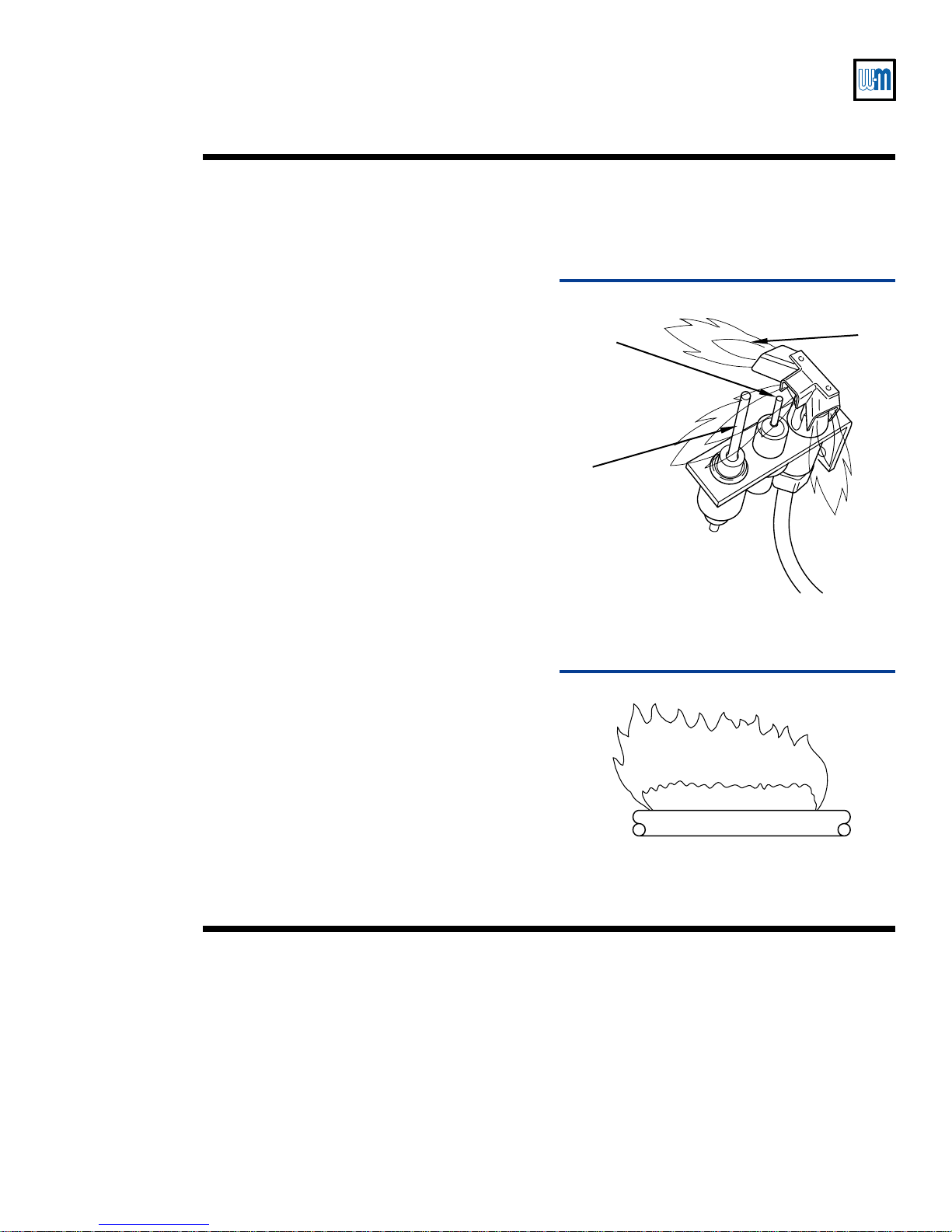
Boiler Manual
Check burner flames
View pilot and main flames through the inspection port
in the base burner shield.
Pilot burner flame
Proper pilot flame characteristics (see Figure 28):
1. Blue flame.
2. Inner cone engulfing pilot flame sensor.
3. Pilot flame sensor glowing cherry red.
Improper pilot flame characteristics:
1. Overfired — Large flame lifting or blowing
past pilot flame sensor.
2. Underfired — Small flame. Inner cone not
engulfing pilot flame sensor.
3. Lack of primary air — Yellow flame tip.
4. Incorrectly heated pilot flame sensor.
Main burner flame
Proper main burner flame characteristics
Figure 29):
(see
1. Yellow-orange streaks may appear (caused by
dust).
Figure 28 Typical pilot burner flame
Spark
electrode
Pilot
flame
sensor
Figure 29 Typical main burner flame
Inner
cone
71030
Improper main burner flame characteristics:
1. Overfired — Large flames.
2. Underfired — Small flames.
3. Lack of primary air — Yellow tipping on
flames (sooting will occur).
Start-up — if boiler doesn’t start . . .7c
Check for:
1. Loose connections, blown fuse or service switch
off?
2. High limit switch set below boiler water
temperature?
3. Thermostat set below room temperature?
4. Gas not turned on at meter or boiler?
Part Number 550-110-710/0200
Transparent
blue flame
Inner flame
71031
5. Incoming gas pressure less than:
5" w.c. for natural gas?
11" w.c. for propane gas?
If none of the above corrects the problem, refer to
Troubleshooting, section 11, pages 46-55 of this
manual.
35
Page 36

GOLD CGi Series 2 Gas-Fired Water Boiler
Check-out procedure — checklist8
❏ Boiler and heat distribution units filled with water?
❏ Automatic air vent, if used, open one full turn?
❏ Air purged from system?
❏ Air purged from gas piping? Piping checked for leaks?
❏ Correctly sized manifold orifices installed? Refer to Table 2,
page 12, to check size and fuel type.
Correctly sized manifold orifices must be
used. Failure to do so will cause severe
personal injury, death or substantial property
damage.
❏ Followed operating instructions on boiler or in manual
section
❏ Proper burner flame observed? Refer to Check burner
flame
❏ Test limit control — While burners are operating, move
indicator on limit control below actual boiler water
temperature. Burners should go off while circulator
continues to operate. Raise setting on limit control above
boiler water temperature and burners should reignite.
❏ Test additional field-installed controls — If boiler has a
low water cutoff, additional high limit or other controls,
test for operation as outlined by manufacturer. Burners
should be operating and should go off when controls are
tested. When controls are restored, burners should reignite.
❏ Test ignition system safety device:
a. Connect manometer to outlet side of gas valve.
b. Start boiler, allowing for normal start-up cycle to occur
c. With main burners on, manually shut off gas supply
d. Open manual main shutoff gas valve. Manometer
9, pages 37-40 for proper start-up?
, manual section 7b, page 35.
and main burners to ignite.
at manual main shutoff gas valve. Burners should go
off.
should confirm there is no gas flow.
e. Pilot will relight, flame sensing element will sense pilot
flame and main burners will reignite.
❏ Set limit control(s) to system temperature requirements.
Adjust balancing valves and controls to provide design
temperature to system.
❏ For multiple zones, adjust flow so it is about the same in
each zone.
❏ Verify thermostat heat anticipator (if available) set properly?
Refer to
Thermostat(s).
❏ Cycle boiler with thermostat — Raise to highest setting
and verify boiler goes through normal start-up cycle. Lower
to lowest setting and verify boiler goes off.
❏ Measure natural gas input:
a. Operate boiler 10 minutes.
b. Turn off other appliances.
c. At natural gas meter, measure time (in seconds)
d. Calculate gas input:
e. Btuh calculated should approximate input rating on
❏ Check manifold gas pressure by connecting manometer to
downstream test tapping on main gas valve. Manifold
pressure for natural gas should be 3.5" w.c. and for propane
gas should be 10" w.c.
❏ Observe several operating cycles for proper operation.
❏ Set room thermostat to desired room temperature.
❏ Fill in Installation and service certificate below?
❏ Review all instructions shipped with this boiler with owner
or maintenance person. Return instructions to envelope
and give to owner or place in pocket inside front panel in
boiler.
Field wiring, manual section 6, page 31,
required to use one cubic foot of gas.
3600 x 1000
number of seconds from step c
boiler rating label.
= Btuh
Installation and service certificate
Boiler model __________________ Series __________ CP number ___________ Date installed _______________
❏ Installation instructions have been followed.
Measured Btuh input ____________
Installer ________________________ ________________________________ ______________________________
(company) (address) (phone)
36
❏ Check out sequence has been performed.
❏ Above information is certified to be correct.
❏ Information received and left with owner/maintenance person
_____________________________________
(installer’s signature)
Part Number 550-110-710/0200
Page 37
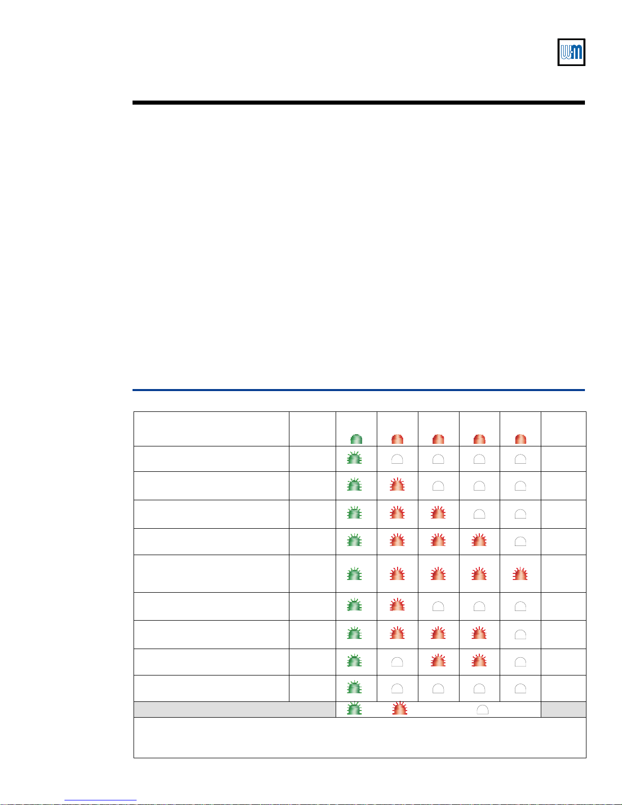
Boiler Manual
Operation — sequence9a
1. Read Operating instructions on page 40. This
information is also located on a label on the inside
of the boiler jacket door panel.
2. Raise room thermostat to call for heat.
3. Inducer and circulator energize. After pressure
switch proves proper airflow, control module
initiates 30-second prepurge.
4. Control module sparks the pilot and opens pilot
valve in main gas valve.
a. If pilot does not light within 15 seconds, pilot
valve is closed and spark generator is turned
off. Control module initiates a 15-second
postpurge, then starts a new cycle.
b. If pilot
does light and control module senses
flame current, spark generator is turned off and
main valve opens.
5. During main burner operation:
a. Control module monitors pilot flame current.
If signal is lost, main valve closes, spark
6. In the event the limit control shuts down the
7. Lower room thermostat setting to stop call for heat.
8. Boiler is now in the
9. Repeat steps 1 through 6 several times to verify
10. Return the thermostat to normal setting.
11. Set thermostat heat anticipator setting as instructed
generator activates and sequence returns to
step
4.
If power is interrupted, control system shuts
b.
off
pilot and main gas valves and restarts at step
1 when power is restored.
boiler — The control module closes the pilot and
main gas valves, but keeps the inducer operating
for 15-second postpurge.
— The circulator continues to operate.
Thermostat is satisfied — Pilot and main gas valves
are closed — Inducer operates for 15-second
postpurge — Circulator is shut off.
off cycle.
operation.
in Figure 32, page 39.
Figure 30 Control module sequence of operation — status light indications
Steps
(Following step 8, cycle goes back to step 1.)
1. Standby
Waiting for call for heat·
2. Call for heat
· Circulator on
· Blower on
3. Limit circuit
· Limit controls closed
· Rollout TFE contacts closed
4. Pressure circuit
· Pressure switch contacts closed
· Prepurge for 30 seconds
5. Pilot flame proven *
· Gas valve open
· Pilot remains on
· Boiler producing heat
6. Limit cycle
· Limit circuit open
· Gas valve closed
7. Flame outage *
· Flame out
· Boiler recycles
8. Thermostat satisfied
· Circulator off
· Blower postpurge
9. Circulator exercise routine
· Circulator turns on for 30 seconds
if boiler not operated for 30 days
Call for
heat?
NO
YES
YES
YES
YES
YES
YES
NO
NO
POWER TSTAT
CIRC
or
* If pilot flame is not proven in 15 seconds, control module will flash the FLAME light, but will continue indefinitely with attempts to light the pilot burner.
The control module will not lockout on a failure to establish flame. It will lockout if line voltage polarity is reversed, stray voltage is sensed on thermostat
line, pressure switch sticks closed or fails to make within 5 minutes or if flame is sensed when it shouldn’t be there. The boiler will reset after these lockouts
if any of the following occurs:
• 1 hour waiting period • Opening and closing of thermostat circuit • Removal of 120 VAC power for at least 45 seconds.
LIMIT
= "ON"
PRESS
SWITCH
FLAME
= "OFF"
Timing
—
—
—
35 sec
15 sec
—
—
15 sec
30 sec
71032
Part Number 550-110-710/0200
37
Page 38
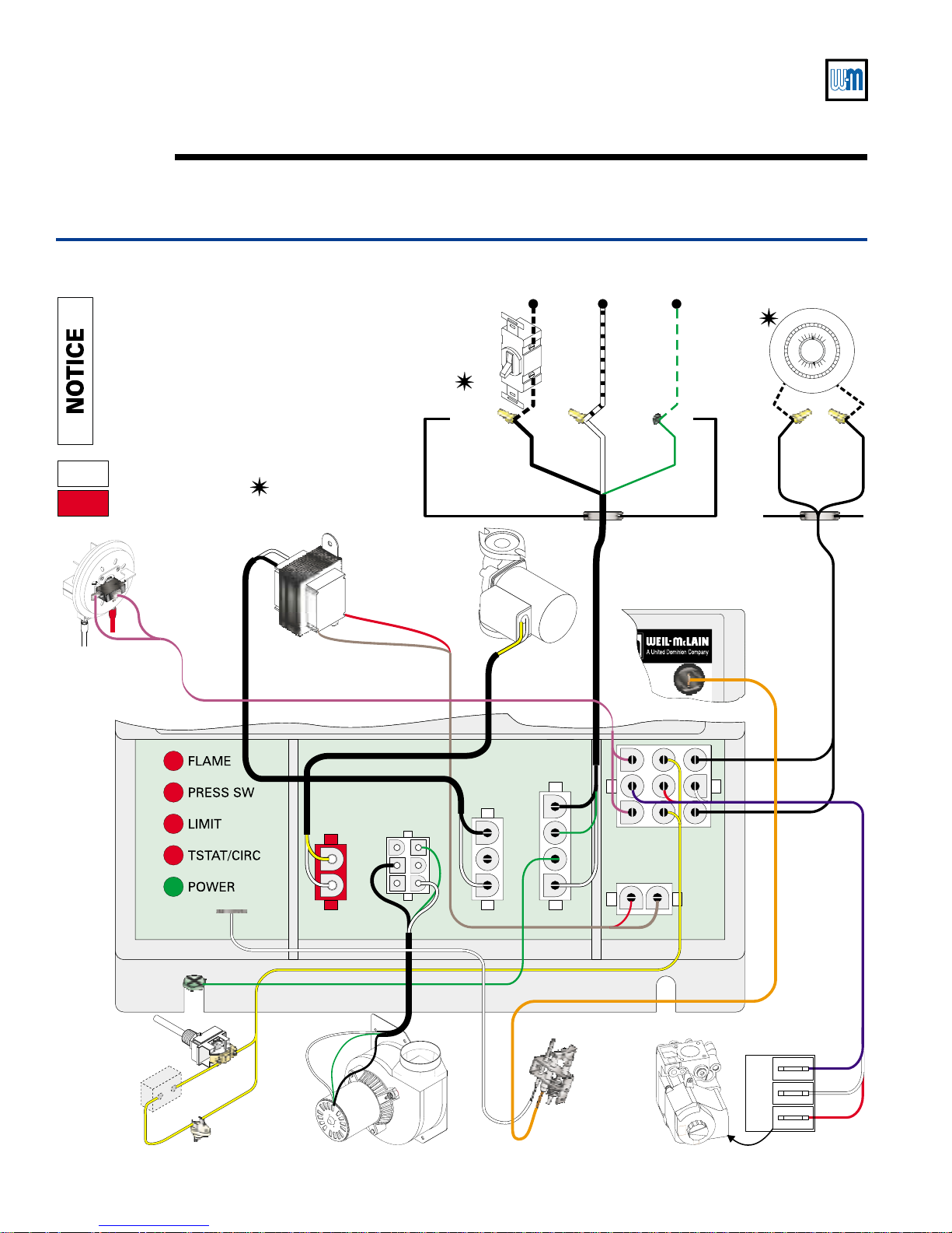
GOLD CGi Series 2 Gas-Fired Water Boiler
THERMOSTAT
Operation — wiring diagrams9b
Figure 31 Schematic wiring diagram
• The control module is polarity-sensitive to the
incoming 120 VAC power. If polarity is reversed,
control will flash the light when powered
POWER
and will not cycle boiler.
• All contacts shown without power applied.
• Connector and status light locations/orientations
may vary.
White
Red
White
hose
Plug-in
connectors
Red
hose
R
AIR PRESSURE
SWITCH
R
Items not provided
W
B
TRANSFORMER
R
BR
120 VAC —
SERVICE
SWITCH
Wire nuts
Black
Junction box,
boiler left side
CIRCULATOR
NeutralHot
Gnd
FIELD
WIRING
THERMOSTAT
70
80
60
60
80
70
Ground
screw
White
Green
Black Black
Jacket opening,
boiler left side
WY
R
B
Y
Y
W
W
WATER
TEMPERATURE
Y
LIMIT SWITCH
Additional
limits,
if used
(note 7)
71034
Y
Y
ROLLOUT
TFE
Y
W
38
B
B
G
BLOWER MOTOR
W
R
B
G
B
G
W
W
G
O
W
PILOT
BURNER
BL
R
R
(Honeywell VR8204 shown)
W
Y
B
BR
"C"
"A"
O
FF
O
N
GAS VALVE
Part Number 550-110-710/0200
"B"
Terminal block
(See Table G)
BL
W
R
Page 39
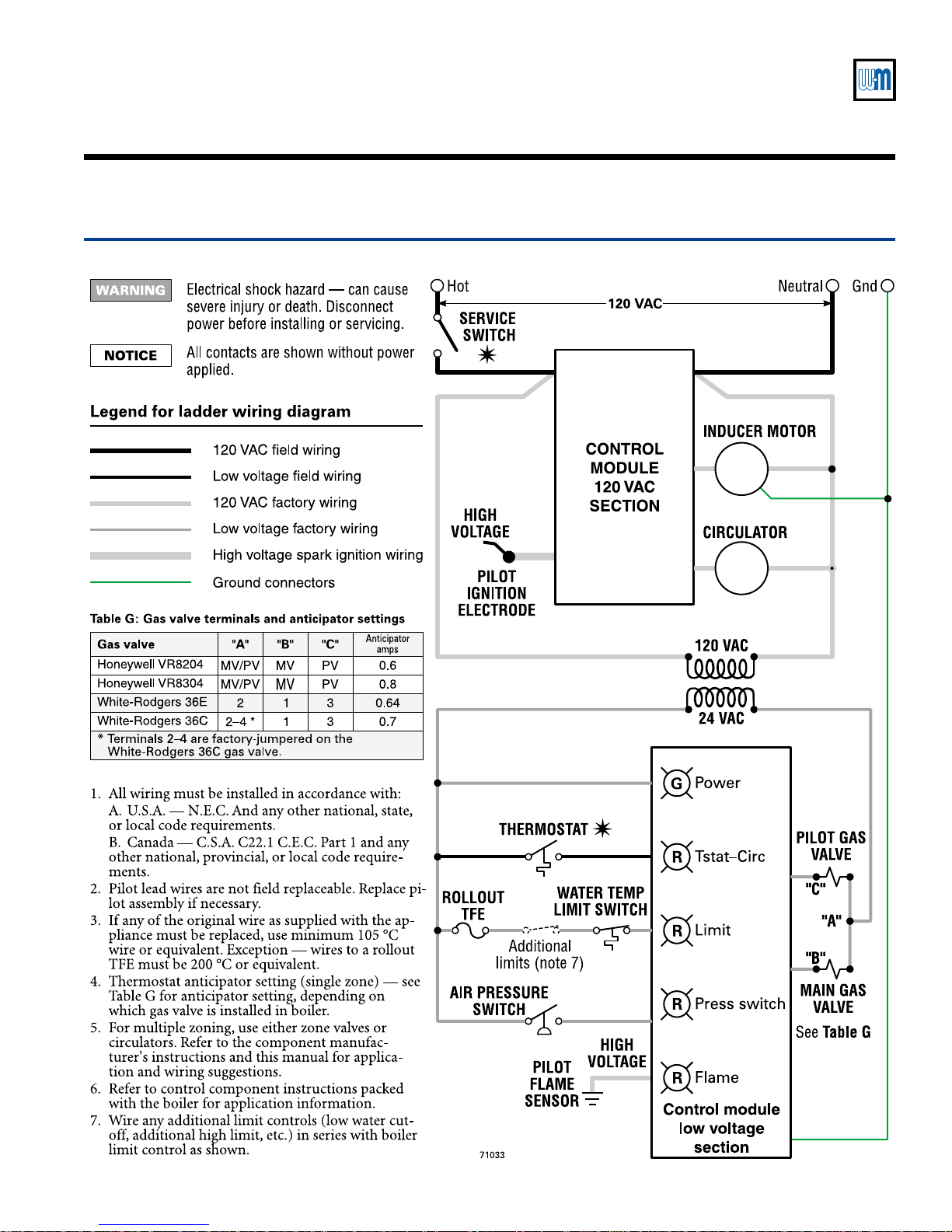
Boiler Manual
Figure 32 Ladder wiring diagram
Part Number 550-110-710/0200
39
Page 40
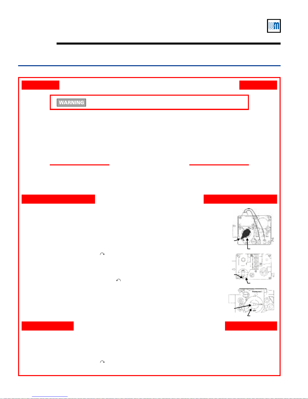
GOLD CGi Series 2 Gas-Fired Water Boiler
Operation — operating instructions9c
Figure 33 Operating instructions
FOR YOUR SAFETY READ BEFORE OPERATING
If you do not follow these instructions exactly, a fire or explosion may
result causing property damage, personal injury or loss of life.
A. This appliance is equipped with an ignition
device which automatically lights the pilot.
try to light the pilot by hand.
not
B. Before
OPERATING, smell all around the
Do
appliance area for gas. Be sure to smell next to
the floor because some gas is heavier than air
and will settle on the floor. See below.
C. Use only your hand to turn the gas control knob. Never use
tools. If the knob will not turn by hand, don't try to repair it,
call a qualified service technician. Force or attempted repair
may result in a fire or explosion.
D. Do not use this appliance if any part has been under water.
Immediately call a qualified service technician to inspect the
appliance and to replace any part of the control system and
any gas control, which has been under water.
WHAT TO DO IF YOU SMELL GAS
• Do not try to light any appliance.
• Do not touch any electric switch; do not use
any phone in your building.
• Immediately call your gas supplier from a neighbor's phone.
Follow the gas supplier's instructions.
• If you cannot reach your gas supplier, call the fire department.
OPERATING INSTRUCTIONS
1. Stop! Read the safety information above on this label.
2. Set the thermostat to lowest setting.
3. Turn off all electrical power to the appliance.
4. Remove jacket front panel.
5. This appliance is equipped with an ignition device which automatically lights the burner.
Do not try to light the burner by hand.
6. Turn Gas control knob clockwise to OFF.
7. Wait five (5) minutes to clear out any gas. Then smell for gas, including near the floor. If
you smell gas, STOP! Follow "B" in the safety information above. If you don't smell gas,
go to the next step.
8. Turn Gas control knob counterclockwise to ON.
9. Turn on all electric power to the appliance.
10. Set thermostat to desired setting.
11. If the appliance will not operate, follow the instructions "To Turn Off Gas To Appliance"
below and call your service technician or gas supplier.
12. Replace jacket front panel.
71035
White-Rodgers
36C Gas valve
Position indicator
(shown in "ON" position)
White-Rodgers
36E Gas valve
Position indicator
(shown in "ON" position)
Honeywell
VR8204 or
VR8304
Gas valve
Position indicator
(shown in "ON" position)
Gas control knob
Gas control knob
Gas control knob
TO TURN OFF GAS TO THE APPLIANCE
1. Set the thermostat to lowest setting.
2. Turn off all electric power to the appliance if service is to be performed.
3. Remove jacket front panel.
4. Turn Gas control knob clockwise to OFF. Do not force.
5. Replace jacket front panel.
40
Part Number 550-110-710/0200
Page 41
Boiler Manual
Service and maintenance — schedule10a
Table 8 Service and maintenance schedules
Service technician
(see following pages for instructions)
Inspect:
• Reported problems
• Boiler area
• Air openings
• Flue gas vent system
• Pilot and main burner flames
• Water piping
• Boiler heating surfaces
• Burners and burner shield
• Condensate drain system
UP
-
Service:
• Inducer motor
• Oiled-bearing circulators
Start-up:
• Perform start-up per manual
NNNUAL START
A
Check/test:
Owner maintenance
(see CGi User’s Information Manual for instructions)
• Check boiler area
Daily
Monthly
Periodically • Test low water cutoff (if used)
Every 6 months
• Check air openings
• Check boiler pressure/
temperature gauge
• Check boiler interior piping
• Check venting system
• Check air vents
• Check boiler relief valve
• Check condensate drain system
• Check automatic air vents (if
used)
• Oil inducer motor
• Operate relief valve
• Gas piping
• Cold fill and operating pressures
• Air vents and air elimination
• Limit controls and cutoffs
• Expansion tank
• Boiler relief valve
Review:
• Review with owner
Part Number 550-110-710/0200
End of season • Shut down procedure
Follow the Service and maintenance procedures given throughout this manual and in
component literature shipped with the boiler. Failure to perform the service and maintenance
could result in damage to the boiler or system. Failure to follow the directions in this manual
and component literature could result in severe personal injury, death or substantial property
damage.
41
Page 42
GOLD CGi Series 2 Gas-Fired Water Boiler
10b
❏ Inspect . . . . . . . . . .
Service and maintenance — annual start-up
The boiler should be inspected and started annually, at the beginning of the heating season, only by a qualified
service technician
the following pages must be performed to assure maximum boiler efficiency and reliability. Failure to service
and maintain the boiler and system could result in equipment failure.
Reported problems
Inspect any problems reported by owner and correct
before proceeding.
Boiler area
1. Verify that boiler area is free of any combustible
materials, gasoline and other flammable vapors and
liquids.
2. Verify that boiler area (and air intake) is free of any
of the
contaminants listed in Table 1 on page 9 of
this manual. If any of these are present in the boiler
intake air vicinity, they must be removed. If they
cannot be removed, isolate the boiler and provide
outside combustion air. See national, provincial or
local codes for further information.
Air openings
1. Verify that combustion and ventilation air openings
to the boiler room and/or building are open and
unobstructed.
2. Verify that boiler vent discharge is
of obstructions
. In addition, the maintenance and care of the boiler designated in Table 8 and explained on
Flue gas vent system
1. Visually inspect entire flue gas venting system
for blockage, deterioration or leakage. Repair any
joints that show signs of leakage in accordance with
vent manufacturer’s instructions. When air is
ducted to boiler, verify that air inlet hose is
connected and properly sealed.
Failure to inspect for the above
conditions and have them repaired
can result in severe personal injury
or death.
Pilot and main burner flames
1. Visually inspect pilot burner and main burner
flames as directed under Start-up, section 7 of this
manual.
Water piping
1. Check the boiler interior piping and all system
piping for signs of leaks.
clean and free
.
Eliminate all system or boiler leaks. Continual fresh makeup water will reduce boiler life.
Minerals can build up in sections, reducing heat transfer, overheating cast iron, and causing
section failure. Leaking water may also cause severe property damage.
Do not use petroleum-based cleaning or sealing compounds in boiler system. Severe damage
to boiler will occur, resulting in substantial property damage.
Electrical shock hazard — Turn off power to the boiler before any service operation on the
boiler except as noted otherwise in this instruction manual. Failure to turn off electrical
power could result in electrical shock, causing severe personal injury or death.
2. Repair any leaks before proceeding.
Boiler heating surfaces
1. Disconnect the vent pipe at the boiler inducer outlet
connection after turning off power to the boiler.
2. Use a bright light to inspect the flue pipe interior
and inducer interior.
3. Inspect the boiler vent outlet area and heating
surfaces by looking through the opening.
4. If the vent pipe or inducer interior show evidence
of soot, follow Cleaning boiler heating surfaces in
this manual section to remove the flue collector and
clean the boiler if necessary after close inspection
The boiler contains ceramic fiber and fiberglass materials. Use care when handling these
materials per instructions on page 64 of this manual. Failure to comply could result in severe
personal injury.
42
of boiler heating surfaces. If there is evidence of
rusty scale deposits, check the water piping and
control system to make sure the boiler return water
temperature is properly maintained (per this
manual).
5. Reconnect vent to inducer outlet and replace all
boiler components before returning to service.
6. Check inside and around boiler for evidence of any
leaks from the boiler. If found, locate source of leaks
and repair.
Part Number 550-110-710/0200
Page 43
Boiler Manual
❏ Inspect . . . . . . . . . .
Burners and base
If insulation is damaged or displaced, do not operate the boiler. Replace or reposition insulation as necessary.
Failure to replace damaged insulation can result in a fire hazard, causing severe personal injury, death or substantial
property damage.
1. After turning off power to the boiler, remove the base burner shield (Figure 40, item 4, page 58).
2. Inspect burners and all other components in the boiler base.
3. If burners must be cleaned, access the burner assembly removing the screws securing the burner tray to the
manifold. Slide the burner tray out. Then brush and vacuum the burners thoroughly, making sure all ports
are free of debris.
4. Inspect the slotted jacket cooling openings in the bottom left and right of the base pan (
page 58).
5. Inspect the base insulation. Pay attention to the
materials. Verify that the insulation is intact and secure against all four sides of the base.
WARNING on page 64 regarding working with insulation
Figure 40, item 7,
Condensate drain system
1. Inspect condensate drain fittings and tubing. Verify that condensate can flow freely to drain.
❏ Service annually. . . . . . . . . .
Inducer motor
1. With boiler power off, place a few drops of S.A.E.
20 motor oil in each of the two oil cups.
Use only S.A.E. 20 motor oil to
lubricate the inducer motor. Do not
use universal household oils. Motor
could be damaged, resulting in
possible severe property damage.
❏ Start-up . . . . . . . . .
1. Perform start-up procedures in section 7, pages 3235 of this manual.
Oiled-bearing circulators
1. The circulator shipped with the CGi boiler is
water-lubricated. No oiling is required.
2. Check other circulators in the system. Oil any
circulators requiring oil, following circulator
manufacturer’s instructions. Over-oiling will
damage the circulator.
4.
Check gas piping, per manual section 5, page 30
and section 7a, page 32, verifying no indications
of leakage and all piping and connections are in
good condition.
2. Verify cold fill pressure is correct and that fill
system is working properly.
3. Verify
Part Number 550-110-710/0200
antifreeze level (if used) is at the right
concentration and that inhibitor level is correct.
5. Read the Operating instructions (Figure 33, page
40
of this manual or on boiler label) applying to
the boiler.
6. Start the boiler following the
instructions
, page 40 of this manual.
Operating
43
Page 44

GOLD CGi Series 2 Gas-Fired Water Boiler
Service and maintenance — annual start-up10b
(continued)
❏ Check/test . . . . . . .
Gas piping
1. Sniff near floor and around boiler area for any indication
2.
gas leak.
of a
Test gas piping using bubble test, per section 5 of this
manual, if there is any indication of a leak.
Cold fill and operating pressures
1. While the system is cold, note the pressure reading on
the boiler pressure/temperature gauge. Verify that cold
fill pressure is correct.
Watch the pressure as the boiler and system heat up to
2.
ensure pressure rise is normal. Too high a rise would
indicate a waterlogged or undersized expansion tank.
Air vents and air elimination
1. Inspect automatic air vents (if used).
Also inspect air separators to ensure
they are operational.
2. The cap must be unscrewed one
turn to allow air to escape.
3. See
4. Replace cap
Figure 34. If the air vent is
leaking, remove cap
push valve
clean the valve seat.
onto valve
one turn.
B and then release to
A by twisting all the way
B and then unscrewing
A and briefly
Figure 34
Automatic air
vent, typical
A
B
71036
Limit controls and cutoffs
1. Inspect and test the boiler limit control. Verify operation
by turning control set point below boiler temperature.
Boiler should cycle off. Return dial to original setting.
2. Inspect and test additional limit controls or low water
cutoffs installed on system.
Expansion tank
1. Expansion tanks provide space for water to move in and
out as the heating system water expands due to
temperature increase or contracts as the water cools.
Tanks may be open, closed or diaphragm or bladder type.
See section
best location of expansion tanks and air eliminators.
Open-type — located above highest radiator or
baseboard unit, usually in the attic or closet. Has a gauge
glass and overflow pipe to a drain.
Closed-type — welded gas tight and located above boiler.
Tank is partially filled with water, leaving an air cushion
for expansion.
• Make sure this type of tank is fitted with a
•
Diaphragm- or bladder-type — welded gas tight with a
rubber membrane to separate the tank pressurizing air
and the water. May be located at any point in the system,
but most often found near the boiler.
• Systems with this type of expansion tank require at
2. If relief valve has tended to weep frequently, the expansion
tank may be waterlogged or undersized.
Closed-type tank — tank is most likely waterlogged.
Install a tank fitting if not already installed. Then check
fill level per fitting manufacturer’s instructions. If fill level
is correct, check tank size against manufacturer’s
instructions. Replace with a larger tank if necessary.
Diaphragm- or bladder-type — first, check tank size to be
sure it is large enough for the system. If size is too small,
add additional tank(s) as necessary to provide sufficient
expansion. If tank size is large enough, remove tank from
system and check charge pressure (usually 12 psig for
residential applications). If tank won’t hold pressure,
membrane has been damaged. Replace tank.
3, pages 14-19 of this manual, for suggested
such as the B & G Tank-Trol or Taco Taco-Trol. This
fitting reduces gravity circulation of air-saturated
tank water back to the system and prevents the air
from bubbling up through the water as it returns
from the system.
Do not use automatic air vents in systems with
closed-type tanks.
system instead of returning to the tank. Eventually,
the tank will waterlog and no longer control
pressurization. The boiler relief valve will weep
frequently.
least one
top of an air eliminator, as shown in examples in
manual section
automatic air vent, preferably located on
The air will escape from the
3, pages 14-19.
tank fitting,
44
Part Number 550-110-710/0200
Page 45
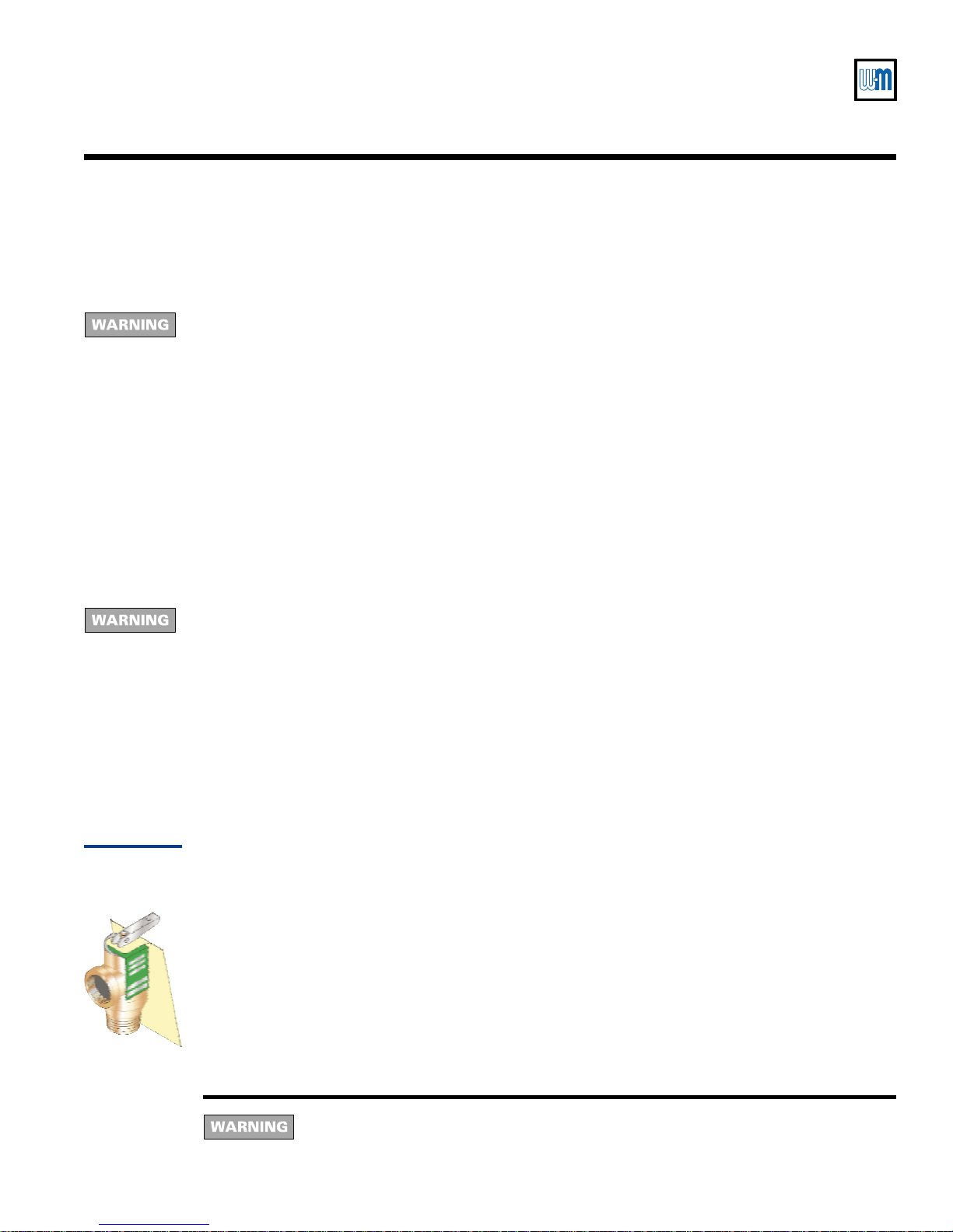
Boiler Manual
❏ Check/test . . . . . . .
Boiler relief valve
Safety relief valves should be reinspected AT LEAST
ONCE EVERY THREE YEARS
contractor or authorized inspection agency, to ensure
that the product has not been affected by corrosive
water conditions and to ensure that the valve and
discharge line have not been altered or tampered with
illegally. Certain naturally occurring conditions may
corrode the valve or its components over time,
rendering the valve inoperative. Such conditions are
not detectable unless the valve and its components are
physically removed and inspected. This inspection must
only be conducted by a plumbing contractor or
authorized inspection agency — not by the owner.
Failure to reinspect the boiler relief valve as directed
could result in unsafe pressure buildup, which can
result in severe personal injury, death or substantial
property damage.
Following installation, the valve lever must be
operated AT LEAST ONCE A YEAR to ensure that
waterways are clear. Certain naturally occurring mineral
deposits may adhere to the valve, rendering it
inoperative. When manually operating the lever, water
will discharge and precautions must be taken to avoid
contact with hot water and to avoid water damage.
Before operating lever, check to see that a discharge
line is connected to this valve directing the flow of hot
water from the valve to a proper place of disposal
otherwise severe personal injury may result. If no water
flows, valve is inoperative. Shut down boiler until a
new relief valve has been installed.
Figure 35
Relief valve,
typical
71037
1. Inspect the relief valve and lift the lever to verify flow as in
the following warnings, excerpted from a relief valve
manufacturer’s warning label. Before operating any relief
valve, ensure that it is piped with its discharge in a safe
area to avoid severe scald potential. Read manual section
3a, page 14, before proceeding further.
2. After following the above warning directions, if the relief
valve weeps or will not seat properly, replace the relief
valve. Ensure that the reason for relief valve weeping is
the valve and not over-pressurization of the system due
to expansion tank waterlogging or undersizing.
, by a licensed plumbing
❏ Review with owner
1. Review the User’s Information Manual with the
owner.
2. Emphasize the need to perform the maintenance
schedule specified in the User’s Information
Manual (and in this manual as well).
3. Remind the owner of the need to call in a licensed
contractor should the boiler or system exhibit any
unusual behavior.
4. Remind the owner to follow the proper shutdown
procedure and to schedule an annual start-up at the
beginning of the next heating season.
❏ Cleaning boiler
heating surfaces
1. Shut down boiler:
• Follow “
• Do not drain boiler unless it will be exposed to freezing
2. Follow shutdown procedure.
3. Remove venting system connection to boiler.
4. Remove top jacket panel. Turn back insulation.
5. Remove collector box/transition assembly. Clean sealant
from assembly and sections.
6. Remove radiation plates hanging between sections.
7. Remove burners from base. Brush and vacuum burners
to remove all dust and lint. Verify that all burner ports
are free of debris.
8. Place newspapers in base of boiler to collect soot.
9. Clean between sections with wire flue brush.
10. Remove newspaper and soot. Vacuum or brush base and
surrounding area.
11. Reinstall radiation plates.
12. Replace collector box/transition assembly. Seal with
sealant. Obtain gas-tight seal to prevent flue gas spillage
and carbon monoxide emissions, resulting in severe
personal injury or death.
13. Replace insulation and jacket top panel.
14. Start up boiler following section
manual and the boiler
sooting indicates improper gas combustion. If found check
for proper combustion and make any necessary
adjustments.
To Turn Off Gas to Appliance” instructions
on boiler and
temperatures. If using antifreeze in system, do not
drain.
Operating instructions.
7, pages 32-35 of this
Operating instructions. Excessive
Part Number 550-110-710/0200
The boiler contains ceramic fiber and fiberglass materials. Use care when handling these
materials per instructions on page 64 of this manual. Failure to comply could result in severe
personal injury.
45
Page 46
GOLD CGi Series 2 Gas-Fired Water Boiler
Boiler model number Inches W.C.
CGi-25 and CGi-3 1.79
CGi-4 1.40
CGi-5 1.12
CGi-6 and CGi-8 0.80
CGi-7 0.75
Troubleshooting — procedure11a
Label all wires prior to disconnection when servicing
controls. Wiring errors can cause improper and
dangerous operation.
Never jumper (bypass) rollout thermal fuse element
or any other device except for momentary testing as
outlined in Troubleshooting Charts. Severe personal
injury, death or substantial property damage can result.
Before troubleshooting:
1. Have the following items:
a. Voltmeter that can check 120 VAC and 24 VAC.
b. Microammeter with a minimum scale range of 0-25.
c. Continuity checker.
d. Inclined manometer with 0 – 2.5" w.c. range.
2. Check for 120 VAC (minimum 102 VAC to maximum 132
VAC) to boiler.
3. Make sure thermostat is calling for heat and contacts
Troubleshooting — components11b
Air pressure switch
Make sure boiler water temperature is 100 °F or cooler
before starting procedure to obtain appropriate
readings.
Check pressure switch setting
1. See Figure 36,page 47 and Table 9.
2. Remove both air pressure switch hoses from air pressure
switch.
3. Install tees and tubing as shown in
inclined manometer.
4. Turn off gas valve and set thermostat to call for heat.
Inducer will run but burners will not ignite.
5. Check for 24 VAC between both air pressure switch
terminals.
6. If manometer reading is above the setpoint of the switch
Troubleshooting air pressure reading
1. If manometer reading is lower than the setpoint of the
46
Table 9), but there is not 24 VAC between both air
(see
pressure switch terminals — replace air pressure switch.
switch (see
• blockage in hoses
• obstruction in inducer housing outlet
• loose inducer wheel on motor shaft
• inducer motor not in proper rpm
• inducer back plate not sealed properly
• blockage in block assembly
• blockage in flue pipe or termination
• incorrect pressure switch
Table 9) — check for possible causes:
Figure 36, page 47 to
(including appropriate zone controls) are closed. Check
for 24 VAC between thermostat wire nuts and ground.
Check the following:
1. Wire connectors to control module are securely plugged
in at module and originating control.
2. Air pressure switch hoses are properly and securely
plugged in and are not damaged.
3. Gas pressures:
a. With boiler off — 13" w.c. maximum natural or
propane gas pressure upstream of gas valve.
b. With boiler on:
• 5" w.c. minimum natural gas pressure or 11" w.c.
propane gas pressure upstream of gas valve.
• 3 ½" w.c. minimum natural gas pressure or 10"
w.c. propane gas pressure downstream tapping
on gas valve — Can be adjusted by regulator on
gas valve.
Return to normal operation
When pressure reading is correct and air pressure switch is
operating properly — remove tees and reinstall hoses to air
pressure switch.
The boiler will not operate correctly
unless pressure switch hoses are
correctly located. The red hose
connects from the right side
(negative) hose barb to the flue
collector. The white hose connects
from the left side (positive) hose
barb of the switch to the connector
box (between flue collector and
inducer) as shown in
page 47.
Table 9
Pressure switch setpoint (for elevations above 2,000
ft, contact your local Weil-McLain sales office for details.)
Part Number 550-110-710/0200
Figure 36,
Page 47
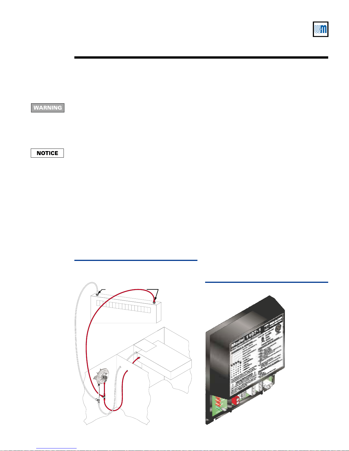
Boiler Manual
Troubleshooting — components (continued)11b
Control module
Solder or water splatter between plugs and circuit
board can cause improper operation of control
module. Place a shield over the boiler internal controls
and components during installation. Failure to comply
could result in severe personal injury, death or
substantial property damage.
Make sure ground wiring is installed per wiring
diagram. Good grounding is extremely important for
proper operation.
Control indicator lights —
lockout modes
See Charts 1 through 7 in this section for detailed
troubleshooting procedures.
To reset control after a lockout, turn off power at the 120 VAC
service switch or turn down all thermostats. Wait 45 seconds.
Then restore power or call for heat.
POWER light flashing alone
Usually indicates reversed polarity of 120 VAC power wires.
Figure 36 Manometer connections
POWER and TSTAT CIRC lights flashing
Usually indicates stray voltage on external thermostat circuit
wires (usually due to miswired 3-wire zone valve).
POWER and PRESS SWITCH lights flashing
Usually indicates pressure switch is closed when it should not
be, or pressure switch failed to close within 5 minutes of
inducer starting.
POWER and FLAME lights flashing
Usually indicates false flame sense or flame sensed when it
shouldn’t be there.
Control indicator lights —
non-lockout modes
FLAME light flashing alone
Usually indicates pilot flame was not established within 15
seconds from application of spark. Control will flash light,
but will continue to cycle indefinitely until flame is established
or problem is corrected.
PRESS SWITCH light flashing alone
Usually indicates pressure switch opened during the run cycle.
Troubleshooting the control module
See Figure 38 for location of harness plug receptacles and plugs
on the control module.
Suction
Inclined tube
manometer
Red
White
Side
panel
Part Number 550-110-710/0200
White
White
Red
Interior panel
Pressure
Red
Flue collector
Rear
panel
71038
Figure 37 Control module
71039
47
Page 48
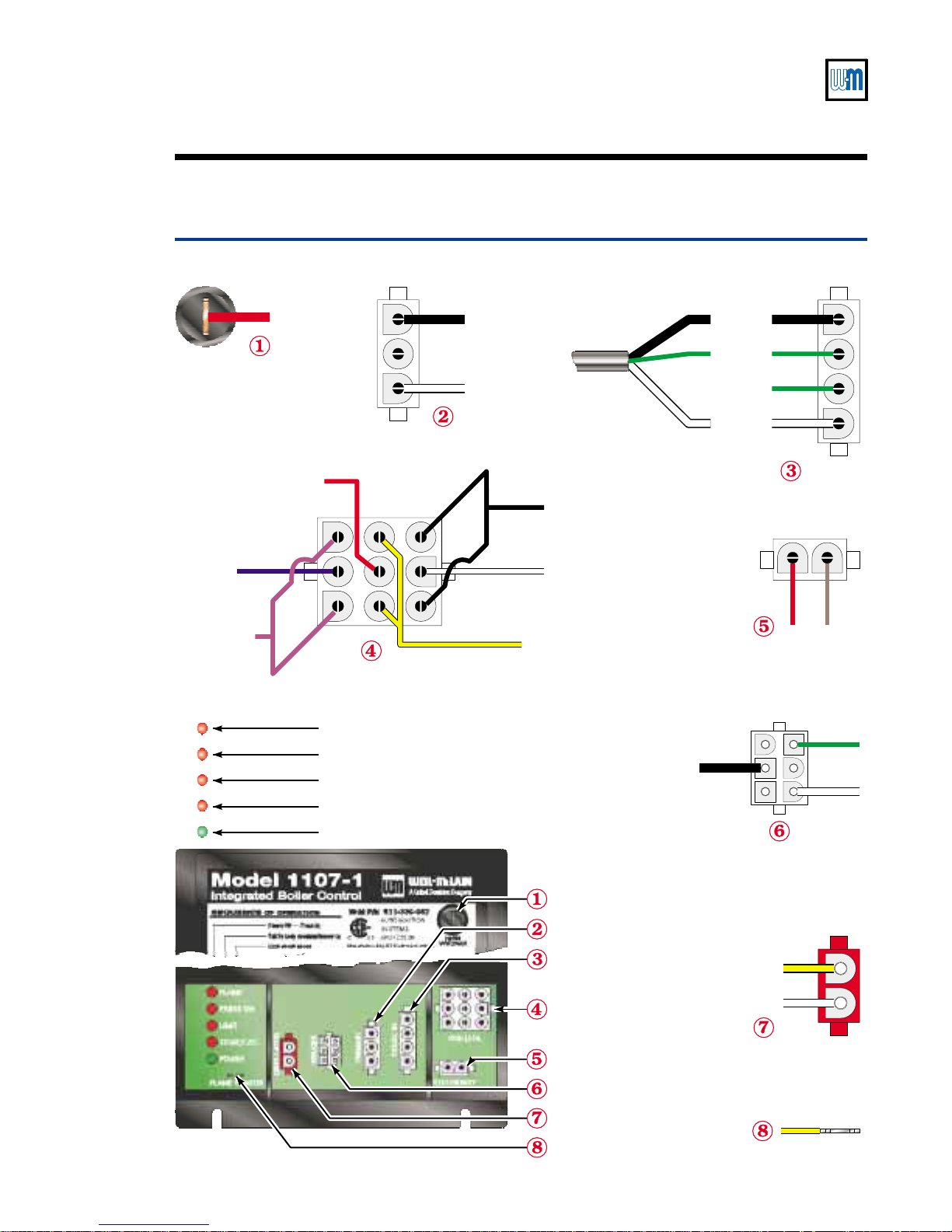
GOLD CGi Series 2 Gas-Fired Water Boiler
Troubleshooting — components continued11b
Figure 38 Control module connections
High voltage to
pilot spark electrode
Blue wire to
gas valve PV
Red wires to
pressure switch
Indicator lights
Red wire to
gas valve MV
24 VAC control
circuits
FLAME
PRESS SWITCH
LIMIT
TSTAT CIRC
POWER
Black
White
120 VAC H
120 VAC N
120 VAC to
transformer
Black wires to
thermostat circuit
White wire to
gas valve MV/PV
Yellow wires to limit control
and rollout switch
SJO cable
to J-box
120 VAC H
120 VAC H
Entrance
ground
Chassis
ground
120 VAC N
24 VAC from transformer
Black
Black
Green
Green
White
120 VAC IN
Red
24 VAC
120 VAC to
inducer motor
Brown
Ground
Green
120 VAC N
White
71040
48
High voltage to spark electrode
120 VAC to transformer
120 VAC IN
24 VAC control circuits
24 VAC from transformer
120 VAC to inducer motor
120 VAC to circulator
Sense wire to flame sensor
Part Number 550-110-710/0200
120 VAC H
120 VAC N
Flame sense wire to pilot
Yellow
White
120 VAC to circulator
Page 49
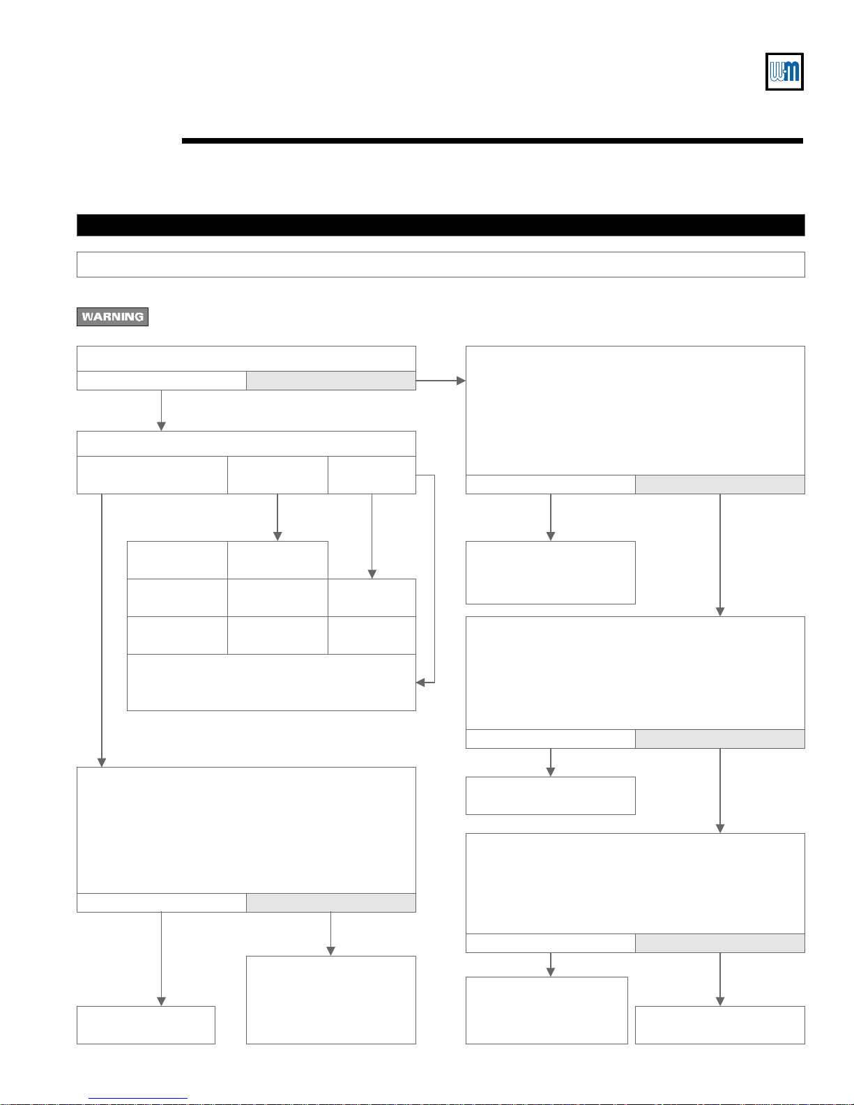
Boiler Manual
Troubleshooting — control module lights11c
CHART 1— Troubleshooting POWER light status
— Usually indicates reversed 120 VAC polarity if POWER light flashes by itself —
Electrical shock hazard — Wherever you see ▲TURN OFF POWER▲, follow the instructions. Failure to follow
instructions could result in severe personal injury, death or substantial property damage.
Is
POWER
No Yes
POWER
Is
Flashing
alone
light off?
light ...
Flashing with
another light
On steady
(not flashing)
• Make sure service switch or circuit breaker is on or
fuses are good.
• Remove 120 VAC IN plug (Figure 38, Item 3, page
48) on control module.
• Using voltmeter, check across top and bottom pins of
120 VAC IN plug.
Does voltmeter indicate
No Yes
120 VAC
?
TSTAT CIRC
light flashing
PRESS SWITCH
light flashing
FLAME
light flashing
For insufficient heat or no heat problem, go to
Chart 7 if POWER light is on steady, with no other
light flashing.
• Usually indicates polarity on incoming 120 VAC power
line is wrong.
• ▲TURN OFF POWER▲ at service switch or breaker,
then reverse the HOT and NEUTRAL wires entering the
boiler in the J-box.
• Restore POWER at service switch or breaker.
Is
POWER
No Yes
Chart
2
Chart
3
Chart
4
light flashing now?
Chart
5
Chart
6
Problem is with incoming
electricity. Have licensed
electrician repair circuit.
• Reconnect 120 VAC IN plug.
• Remove 120 VAC IN transformer PRIMARY plug
(Figure 38, Item 2, page 48) on control module.
• Using voltmeter, check across top and bottom pins of
PRIMARY receptacle.
Does voltmeter indicate
No Yes
Replace control module.
Retest.
• Reinstall 120 VAC transformer PRIMARY plug.
• Remove 24 VAC transformer plug (Figure 38, Item 5,
page 48) on control module.
• Using voltmeter, check pins of plug.
Does voltmeter indicate
No Yes
120 VAC
24 VAC
?
?
Have system checked by a
licensed electrician. If
problem persists, call your
Boiler should now
operate normally.
Part Number 550-110-710/0200
local Weil-McLain sales
representative.
Replace transformer.
Retest and check for back
feed of voltage from
system wiring.
Replace control module.
Retest.
49
Page 50
GOLD CGi Series 2 Gas-Fired Water Boiler
Troubleshooting — control module lights11c
CHART 2 — TSTAT CIRC & POWER lights flashing
— Usually indicates 48 VAC on thermostat circuit (stray voltage) —
Electrical shock hazard — Wherever you see ▲TURN OFF POWER▲, follow the instructions. Failure to follow
instructions could result in severe personal injury, death or substantial property damage.
• Disconnect the two external wires connected to the boiler
thermostat leads (two black low voltage leads in J-box).
• Connect a voltmeter across these two incoming wires.
Close each thermostat, zone valve and relay in the
external circuit one at a time and check the voltmeter
reading across the wires.
• There should NEVER be a voltage reading.
Did you find a voltage across the two external thermostat circuit wires?
• Leave external boiler thermostat connection wires
disconnected from boiler.
• Troubleshoot the external thermostat circuit until you find
the source of the stray voltage. (Pay close attention to
the wiring connections to 3-wire zone valves.)
• Correct the problem and repeat the voltmeter test above,
verifying there is no longer a voltage reading under any
condition in the external thermostat circuit.
• An isolating relay may be required.
• If a voltage does occur under any condition, check and
correct the external wiring. (This is a common problem
when using 3-wire zone valves.)
• Once the external thermostat circuit wiring is checked and
corrected if necessary, reconnect the external thermostat
circuit wires to the boiler thermostat wires and allow the
boiler to cycle.
NoYes
• If no voltage is found under any condition of the external
thermostat circuit, connect the two boiler thermostat
connection leads together (or jumper the boiler aquastat
T-T terminals).
• Turn off power to the boiler for 1 minute.
• Turn on power and allow boiler to cycle.
Do the
TSTAT
No Yes
and
POWER
lights still flash?
• Boiler should now operate per the normal sequence of
operation shown in Figure 30, page 37.
50
• Replace control module.
• Retest.
Part Number 550-110-710/0200
Page 51
Boiler Manual
continued
CHART 3 — PRESS SWITCH & POWER lights flashing
— Usually indicates pressure switch stuck closed or failed to make within 5 minutes —
Electrical shock hazard — Wherever you see ▲TURN OFF POWER▲, follow the instructions. Failure to follow
instructions could result in severe personal injury, death or substantial property damage.
• Reset boiler control by turning off power at service switch or turning down thermostat for at least 45 seconds.
• Thermostat should call for heat and appropriate zone valves open.
Does inducer motor operate?
No Yes
• Wait 45 seconds.
Does inducer motor operate?
No Yes
• Remove INDUCER plug (Figure 38, Item 6
from plug receptacle of control module.
• Place voltmeter leads across the 120 VAC N and
120 VAC H pins of the INDUCER receptacle (left
column center and right column bottom pins).
Does the voltmeter indicate
No Yes
• Try reseating plug in
• If inducer still does not
• Retest.
• Remove one of the wires connected to the pressure
switch.
• Check continuity across the switch terminals.
120 VAC
module receptacle and
restart.
work, replace inducer
assembly.
, page 48
?
Does the ohmmeter indicate the switch is closed?
No Yes
)
• Wait 5 minutes.
Is
PRESS SWITCH
No Yes
• Boiler should be in
normal operating
sequence.
• Observe operation until
thermostat is satisfied
and inducer has
completed its post-purge
cycle.
light flashing?
Are vent or combustion air
passages blocked?
No Yes
• Replace control
module.
• Retest.
Part Number 550-110-710/0200
• Check air pressure switch
per manual Section 11.
• Replace if necessary.
• Retest.
• Clear passages and
recycle boiler.
• Recheck boiler operation.
51
Page 52
GOLD CGi Series 2 Gas-Fired Water Boiler
Troubleshooting — control module lights11c
CHART 4 — FLAME & POWER lights flashing
— Usually indicates flame sensed when it shouldn't be there —
Electrical shock hazard — Wherever you see ▲TURN OFF POWER▲, follow the instructions. Failure to follow
instructions could result in severe personal injury, death or substantial property damage.
Are manual main shutoff valve and gas valve open?
No Yes
• Leave main manual gas valve closed.
• Turn off power to boiler at service switch or breaker.
• Wait at least 45 seconds.
• Turn on power to boiler.
• Restart boiler, following Operating instructions in this
manual (Figure 33, page 40).
Do
FLAME
• ▲TURN OFF POWER▲
to boiler at service switch
or breaker.
• Open main manual gas
valve.
• Turn on power to boiler
at service switch or
breaker.
• Restart boiler per lighting
instructions.
• Perform start-up
procedures in boiler
manual to verify proper
operation.
and
POWER
lights still flash?
YesNo
• Replace control module.
• Retest.
• Allow boiler to continue cycling.
Are
FLAME&POWER
No
• Boiler may now be
operating
normally.
• Perform start-up
procedures in
boiler manual to
verify proper
operation.
• Replace control
• Retest.
• Turn off power to the boiler at service switch or breaker.
• Wait at least 45 seconds.
• Turn on power to boiler.
• Restart boiler, following Operating instructions in this
manual (Figure 33, page 40).
• Look through the pilot inspection port to see if the pilot is
burning during the prepurge period (first 30 seconds of
operation).
lights flashing?
Yes
module.
Is pilot burning during prepurge period?
No
• Replace gas valve.
• Retest boiler.
Are
FLAME
• Boiler should now
operate normally.
• Original flashing
FLAME light
caused by gas
valve not
operating
properly.
• See normal
sequence of
operation,
Figure 30,
page 37.
and
No
POWER
Yes
lights flashing?
Yes
• Replace control
module.
• Retest.
52
Part Number 550-110-710/0200
Page 53
Boiler Manual
continued
CHART 5 — PRESS SWITCH light flashing and POWER light on steady
— Usually indicates pressure switch opened during run cycle —
— May also be caused by wind gusts in excess of 31 mph for non-direct vent sidewall-vented boilers —
Electrical shock hazard — Wherever you see ▲TURN OFF POWER▲, follow the instructions. Failure to follow
instructions could result in severe personal injury, death or substantial property damage.
• Reset boiler control by turning off power at service switch or turning down thermostat for at least 45 seconds.
• Thermostat should call for heat and appropriate zone valves open.
Does blower motor operate?
No Yes
• Remove INDUCER plug (Figure 38, Item 6
from plug receptacle of control module.
• Place voltmeter leads across the 120 VAC N and
120 VAC H pins of the INDUCER receptacle (left
column center and right column bottom pins).
Does the voltmeter indicate
No Yes
• Remove one of the wires connected to the pressure
switch.
• Check continuity across the switch terminals.
120 VAC
• Replace inducer
assembly.
• Retest.
, page 48
?
Does the ohmmeter indicate the switch is closed?
No Yes
• Inspect and check wire
harness from control
module to pressure switch.
• Reseat connector in control
module receptacle.
• If harness is intact and
properly seated, but
problem persists, replace
control module.
• Retest.
• Check air pressure switch per manual Section
11b.
• Replace if necessary. Retest.
)
• Wait 5 minutes.
Is
PRESS SWITCH
No Yes
• Boiler should be in
normal operating
sequence.
• Observe operation
until thermostat is
satisfied and inducer
has completed its
post-purge cycle.
light flashing?
Is vent blocked?
No Yes
• Clear vent and recycle boiler.
• Recheck boiler operation.
Part Number 550-110-710/0200
53
Page 54
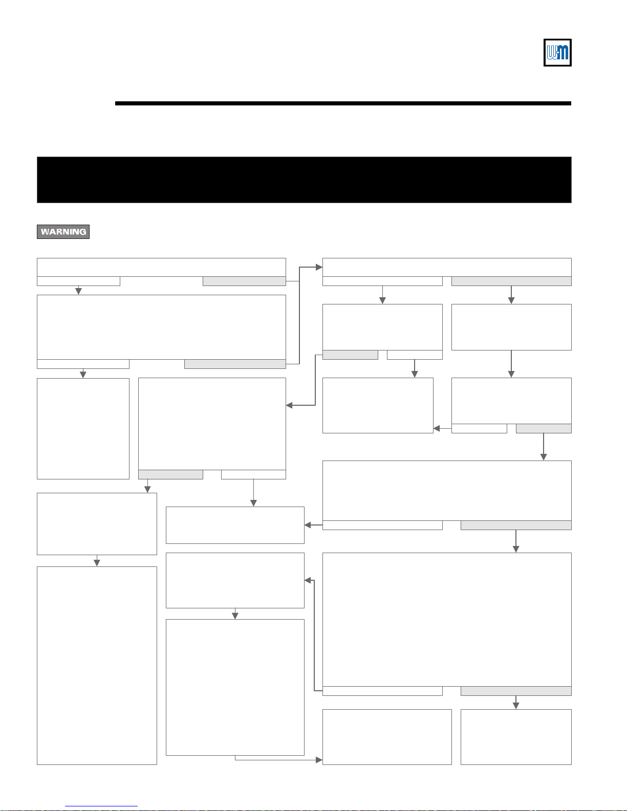
GOLD CGi Series 2 Gas-Fired Water Boiler
Troubleshooting — control module lights11c
CHART 6 — FLAME light flashing and POWER light on steady
ALSO — Troubleshooting failure to establish main flame
Electrical shock hazard — Wherever you see ▲TURN OFF POWER▲, follow the instructions. Failure to follow
instructions could result in severe personal injury, death or substantial property damage.
No Yes
• ▲TURN OFF POWER▲ to boiler at service switch or breaker.
• Open main manual shutoff valve and boiler gas valve (per
Operating instructions in this manual).
seconds.
• Turn on power at service switch or breaker. A
Does
FLAME
No Yes
light flash now?
Wait at least 45
llow boiler to cycle.
(continued)
• Is pilot flame visible through inspection port?• Are main manual shutoff valve and boiler gas valve open?
No Yes
• Check the voltage across
terminals PV and PV/MV of
the gas valve.
Is
24 VAC
present there?
NoYes
• Make sure ground wire
terminal is securely fastened
to control module mounting
screw.
• Boiler should be in
• Verify inlet gas pressure at gas
normal operating
sequence.
• Observe operation
until thermostat is
satisfied and blower
has completed its
post-purge cycle.
• ▲TURN OFF POWER▲ to
boiler at service switch or
breaker.
• Remove burner shield (see
Figure 40, page 58 for
location).
• Verify pilot gas line is not
kinked, obstructed or damaged
and is correctly attached to
pilot and gas valve.
• Verify pilot ignition electrode,
electrode ceramic and spark
lead wire from control are in
good condition. Spark gap
should be approximately 1/8".
• Correct any above problems,
replacing pilot if burner or
wiring is damaged.
• Reinstall burner shield to
operate boiler for retest after
any changes or corrections.
• If none of the above corrects
problem, then replace the
control module and retest.
valve:
Natural gas — 5.0" w.c. min/14.0"
w.c. max
Propane — 11.0" w.c. min/14.0"
w.c. max
Is gas present at gas valve inlet and
within above range?
Yes
• Contact gas supplier to correct
pressure or gas supply.
• ▲TURN OFF POWER▲ to boiler
at service switch or breaker.
• Remove burner shield (see
Figure 40, page 58 for location).
• Verify pilot burner is securely
attached to pilot bracket, bracket is
securely attached to cross tie, and
there is no corrosion on the parts
which would affect the ground path
for flame sense.
• Verify that pilot flame rod, flame rod
ceramic and lead wire from control
module to flame rod are in good
condition.
• Correct any above problems,
replacing pilot if burner or wiring is
damaged.
No
• If the wiring from the
control module to gas
valve is intact, replace the
control module.
• Retest.
• Verify inlet gas pressure at gas valve:
Natural gas — 5.0" w.c. min/14.0" w.c. max
Propane — 11.0" w.c. min/14.0" w.c. max
Is gas present at gas valve inlet and within above range?
No
• ▲TURN OFF POWER▲ to boiler at service switch or breaker.
• Check flame signal — Detach sense lead from ignition control
(Figure 38, item 8,
• Connect negative lead of MICROAMMETER to control sense
terminal (Figure 38, item 8
of MICROAMMETER to sense wire.
• DISCONNECT red wire connected to terminal MV of the gas
valve.
• Turn on power to boiler and allow to cycle. As soon as pilot is
burning, the MICROAMMETER should read at least 1.0
microamp.
Is flame signal at least 1.0 microamp?
No Yes
• If none of the previous steps
(including replacing pilot)
corrects problem, then replace
the control module, reinstall
burner shield and retest.
page 48
• Check the voltage across
terminals MV and PV/MV of
the gas valve.
Is
24 VAC
).
, page 48
• If the wiring from the
present there?
No Yes
Yes
). Connect positive lead
control module to gas
valve is intact, replace the
control module and retest.
54
Part Number 550-110-710/0200
Page 55
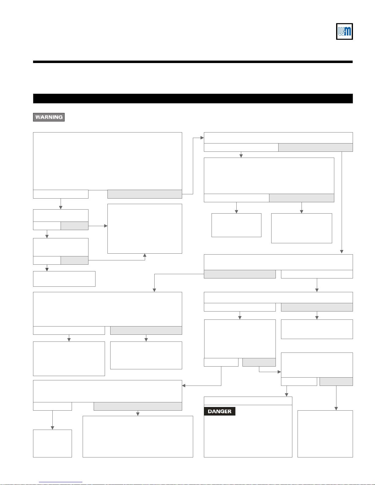
Boiler Manual
CHART 7 — Insufficient heat or no heat to system (POWER light on steady)
Electrical shock hazard — Wherever you see ▲TURN OFF POWER▲, follow the instructions. Failure to follow
instructions could result in severe personal injury, death or substantial property damage.
• Has it been at least 5 minutes since setting thermostat to
call for heat? If not, wait 5 minutes. Is system heating?
• Is thermostat set to call for heat? Remove thermostat
wires at boiler and check continuity across the two wires.
If circuit isn't closed, check external thermostat (zone
valve, relay, etc.) wiring. Correct problems and retry.
• Reconnect external thermostat wiring at boiler.
Is thermostat circuit closed (continuity across wires)?
No Yes
• Boiler is in standby.
Are all red lights off?
No Yes
Wait 30 seconds.
Are all red lights off?
No Yes
Replace control
module. Retest.
• If you have sufficient heat — boiler should be in normal
operating sequence. (See normal sequence of
operation, Figure 30.)
• If you have less than sufficient heat —
• Set thermostat to call for
heat and recheck
operation.
• Verify Sequence of
operation, Figure 30,
page 37.
Is vent piping free of blockage?
No Yes
• Correct conditions and
recheck operation.
• See Figure 30, page 37
for normal sequence of
operation.
• Wait for boiler water to cool to temperature 20 to 30 ˚F
lower than temperature set on limit switch.
• Check heat loss
calculation versus boiler
size.
• Clock gas input.
Are limit switch contacts closed?
No Yes
•
Boiler water temperature exceeded
setting on limit switch with thermostat
• Replace
limit switch.
• Retest.
calling for heat. Boiler is OK. (See normal
sequence of operation,
• Also check setting on limit switch (should
be above 140˚F.).
Figure 30
, p. 37.)
Is boiler System circulator operating?
No Yes
• Remove CIRCULATOR harness plug from
CIRCULATOR plug receptacle (Figure 38, Item
, page 48
7
control module receptacle.
). Check with voltmeter across pins of
Does voltmeter show 120 VAC across pins?
No Yes
• Replace control
module.
• Retest.
• Wait 5 minutes.
No Yes
• Check limit switch
contacts with continuity
checker.
• Repair/replace
• Repair/replace
Is
FLAME
Is
LIMIT
circulator. Retest.
wiring. Retest.
light on?
NoYes
light on?
• Replace control module.
• Retest.
Are limit switch contacts
closed?
No Yes
Check rollout switch
continuity — is switch
closed?
No Yes
• Replace rollout switch.
If rollout thermal fuse element has
opened, determine cause and
correct condition. Failure to do so
will cause severe personal injury,
death or substantial property
damage.
• Check any other
limit controls wired
into the limit
circuit. If all are
OK, then replace
control module.
• Retest.
Part Number 550-110-710/0200
55
Page 56
GOLD CGi Series 2 Gas-Fired Water Boiler
Replacement parts12a
Section assembly................................................ 57
Base assembly .................................................... 58
Jacket assembly ................................................. 59
Trim assembly ..................................................... 60
Gas control assembly ......................................... 61
Replacement parts must be purchased through a local Weil-McLain
distributor. When ordering, specify boiler model and size and include
description and part number of replacement part. Results from using
modified or other manufactured parts will not be covered by warranty
and may damage boiler or impair operation.
Weil-McLain part numbers are found in Weil-McLain Boilers and Controls
Repair Parts Lists
.
56
The boiler contains ceramic fiber and fiberglass materials. Use care when
handling these materials per instructions on page 64 of this manual. Failure
to comply could result in severe personal injury.
Part Number 550-110-710/0200
Page 57
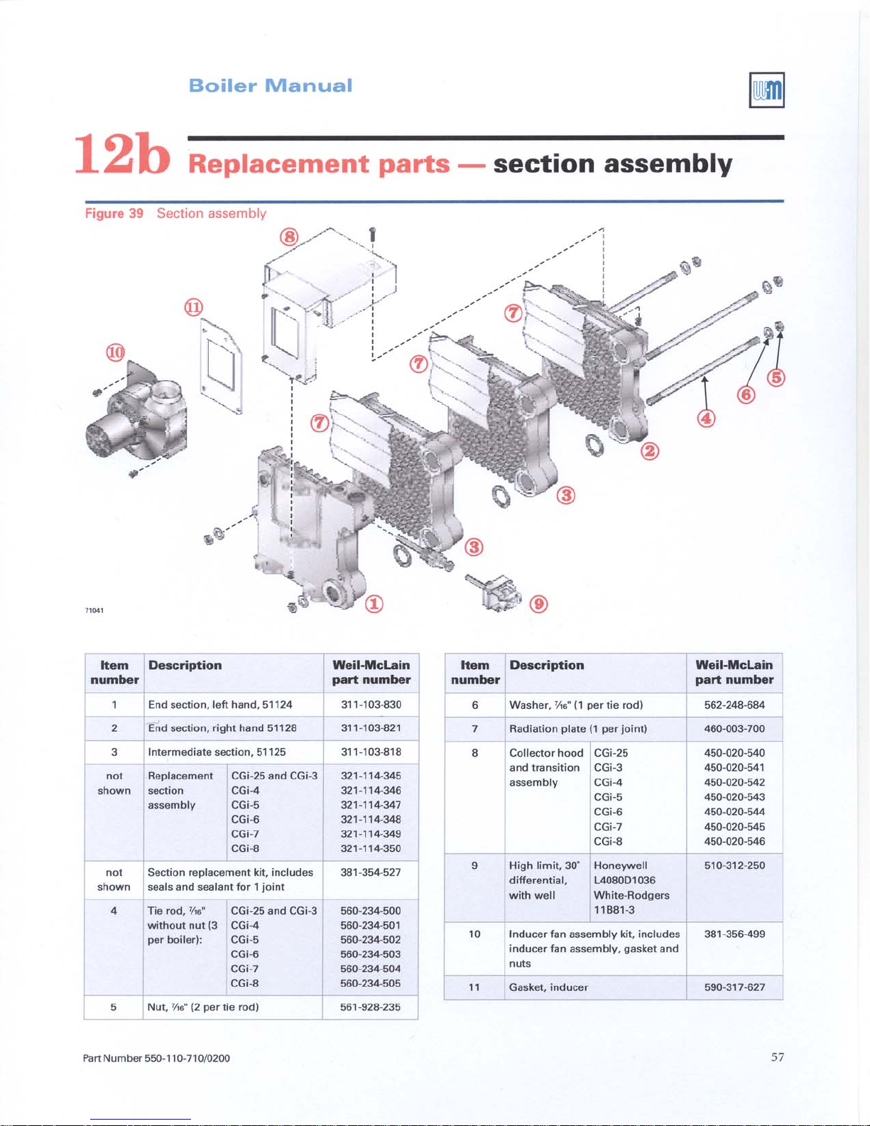
Page 58
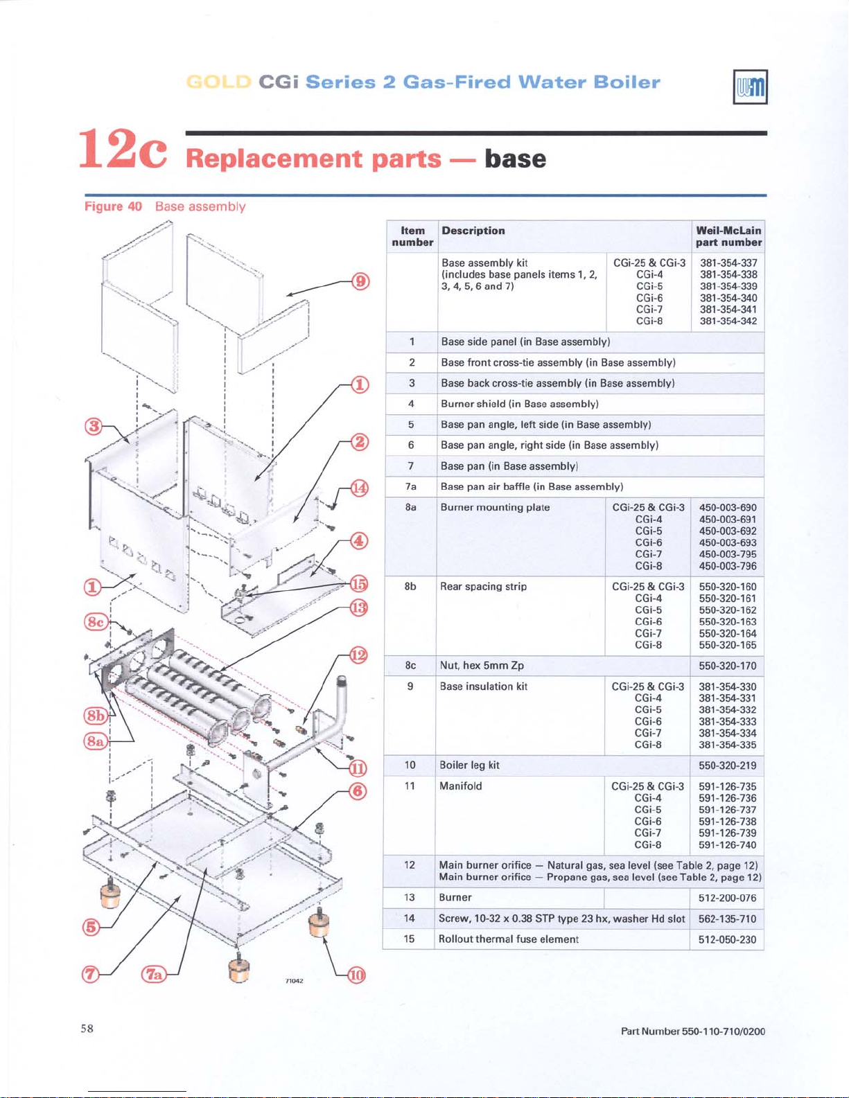
Page 59
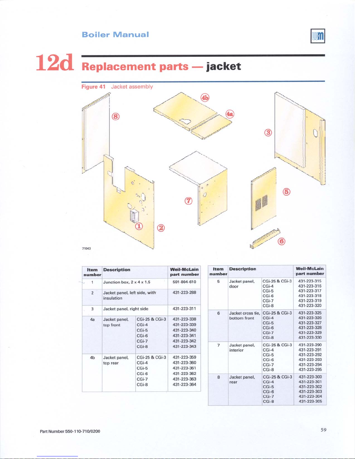
Page 60
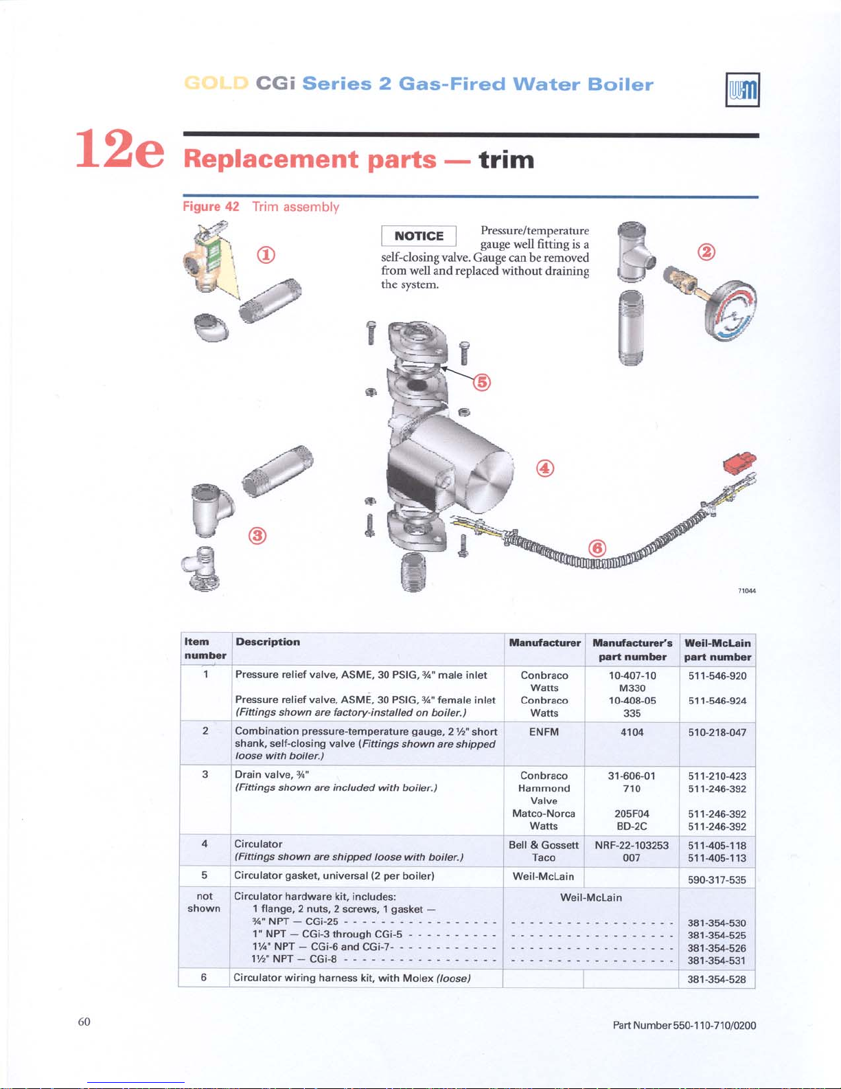
Page 61
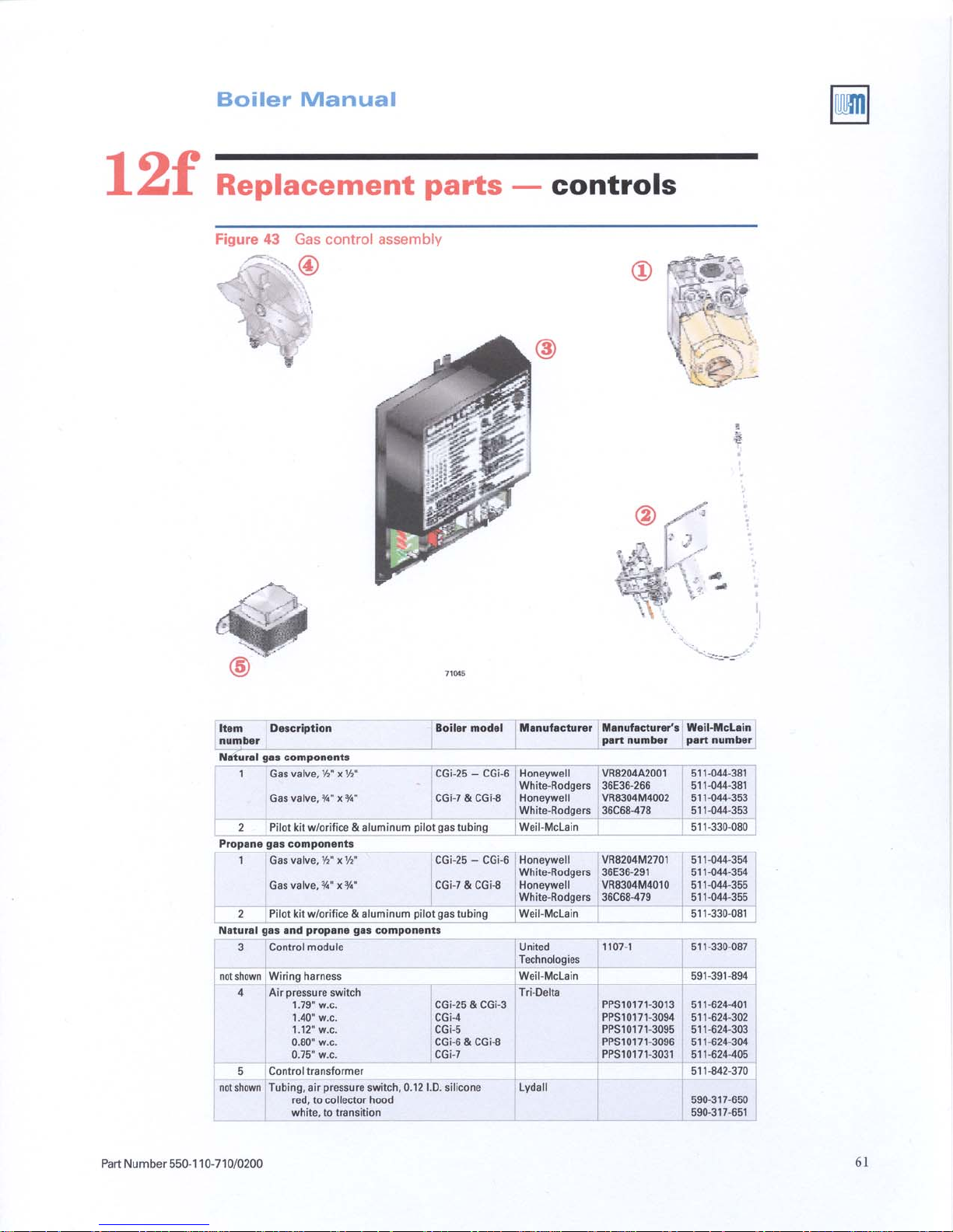
Page 62
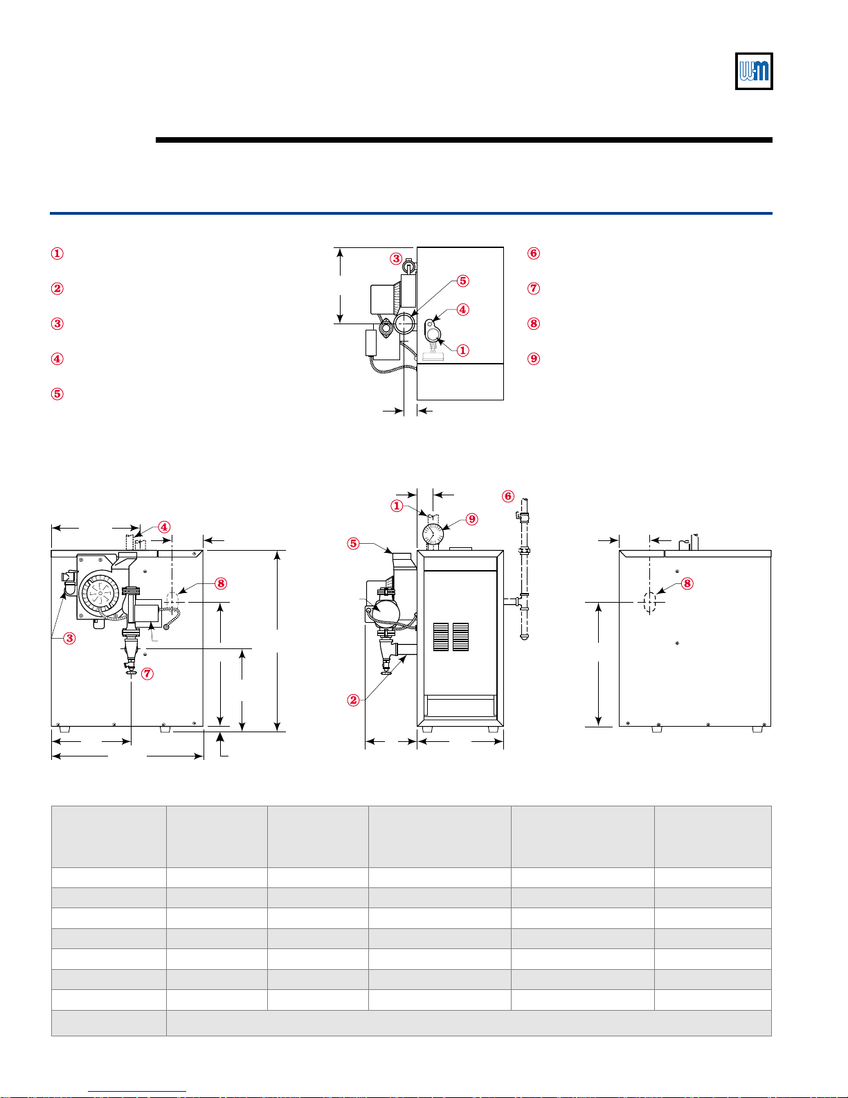
GOLD CGi Series 2 Gas-Fired Water Boiler
Dimensions13a
Figure 44 Dimensional drawing
Supply piping ( )
Return piping ( )
note 1
note 1
Relief valve, ¾" NPT
½" NPT to expansion tank/air vent
3" Diameter vent
A LL DIMENSIONS IN INCHES
13¹⁄₄
4³⁄₄
NOTE 2
19 19
28³⁄₈
11¹⁄₈
NOTE 2
2¹⁄₄
T OP VIEW
2³⁄₈
MODEL
CGi
Gas supply piping
Drain valve
Gas supply entrance (right or left side)
Pressure/temperature gauge
Boiler supply and return tappings are both 1¼" NPT.
Note 1:
See , page 20 for recommended system sup-
Table 6
ply and returnpiping sizes.
Boiler circulator is shipped loose. Circulator may be
Note 2:
mounted on either boiler supply or return piping.
Circulator flange provided with boiler is same size as
recommended pipe sizein , page 20.Table6
4³⁄₄
13¹¹₁₆
12
71046
Boiler
model
number
23¹⁄₄
(inches NPT)
1⁵⁄₈
Supply
tapping
(inches NPT)
CGi-25 1¼ 1¼ ½ ½ 10
CGi-3 1¼ 1¼ ½ ½ 10
CGi-4 1¼ 1¼ ½ ½ 13
CGi-5 1¼ 1¼ ½ ½ 16
CGi-6 1¼ 1¼ ½ ½ 19
CGi-7 1¼ 1¼ ¾ ¾ 22
CGi-8 1¼ 1¼ ¾ ¾ 25
Note 3: Gas piping from meter to boiler to be sized per local utility requirements.
62
Return
tapping
9
W
F RONT
Gas
connection size
Note 3
(inches NPT)
Gas
manifold size
Note 3
(inches NPT)
R IGHT SIDEL EFT SIDE
“W”
Jacket
width
(inches)
Part Number 550-110-710/0200
Page 63
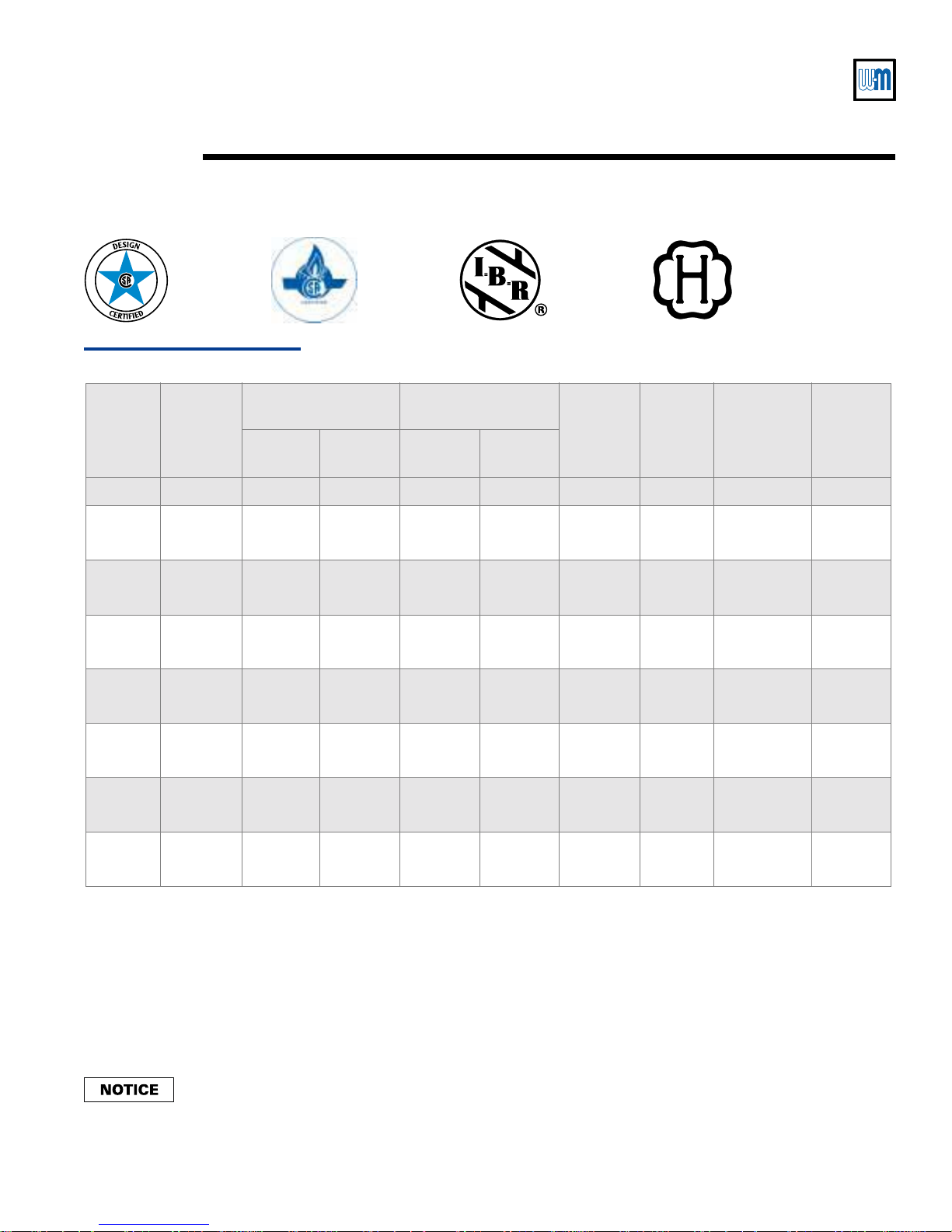
Boiler Manual
13b
Ratings
Table 10 Boiler ratings
Boiler
model
number
(Note 1) (Note 2) (Note 3)
CGi-25 42,000 50,000 42,000 45,000 38,000 37,000 1.5 84.0 3"
CGi-3 57,000 67,000 57,000 60,000 51,000 50,000 1.5 84.3 3"
CGi-4 85,000 100,000 85,000 90,000 76,000 74,000 2.1 84.0 3"
DOE
Heating
capacity
(Btuh)
0–2,000 feet
altitude
Input
(Btuh)
Output
(Btuh)
2,000–4,500 feet
altitude
Input
(Btuh)
Output
(Btuh)
Net
I=B=R
ratings
(Btuh)
Boiler
water
content
(gallons)
DOE
Seasonal
efficiency
(% A.F.U.E)
DOE
Vent
size
(Note 4)
CGi-5 112,000 133,000 112,000 120,000 101,000 97,000 2.7 83.7 3"
CGi-6 140,000 167,000 140,000 150,000 126,000 122,000 3.3 83.3 3"
CGi-7 167,000 200,000 167,000 180,000 150,000 145,000 3.8 83.0 3"
CGi-8 194,000 233,000 194,000 210,000 175,000 169,000 4.4 82.7 3"
Notes
1. Add “PIN” for natural gas boiler - “PIL” for propane gas
boiler.
2. Based on standard test procedures prescribed by the
United States Department of Energy.
3. Net I=B=R ratings are based on net installed radiation of
sufficient quantity for the requirements of the building
and nothing need be added for normal piping and
pickup. Ratings are based on a piping and pickup
allowance of 1.15. An additional allowance should be
made for unusual piping and pickup loads.
4. CGi boilers require special venting, consistent with
Category I or III boiler. Use only the vent materials and
methods specified in this manual. Vent diameter shown
above is for direct exhaust venting. See
for vent diameter when chimney draft venting.
Table 3, page 14,
CGi boilers for residential radiant panel systems, converted gravity heating systems or other low water temperature
applications should be installed with balancing valves and bypass piping equal to the supply and return size to
avoid excessive flue gas condensation due to lower operating water temperatures. For alternate piping, contact
your Weil-McLain sales office. CSA design certified for installation on combustible flooring. Tested for 50 psi
working pressure.
Part Number 550-110-710/0200
63
Page 64
GOLD
CGi Series 2 Gas-Fired Water Boiler — Boiler Manual
Handling fiberglass and ceramic fiber materials
REMOVAL OF COMBUSTION CHAMBER LINING OR BASE PANELS
The combustion chamber lining or base insulation panels in this product contain ceramic fiber materials. Ceramic
fibers can be converted to cristobalite in very high temperature applications. The International Agency for
Research on Cancer (IARC) has concluded, "Crystalline silica inhaled in the form of quartz or cristobalite from
occupational sources is carcinogenic to humans (Group 1).":
■ Avoid breathing dust and contact with skin and eyes.
• Use NIOSH certified dust respirator (N95). This type of respirator is based on the OSHA requirements
for cristobalite at the time this document was written. Other types of respirators may be needed depending
on the job site conditions. Current NIOSH recommendations can be found on the NIOSH web site at
http://www.cdc.gov/niosh/homepage.html. NIOSH approved respirators, manufacturers, and phone
numbers are also listed on this web site.
• Wear long-sleeved, loose fitting clothing, gloves, and eye protection.
■ Apply enough water to the combustion chamber lining or base insulation to prevent airborne dust.
■ Remove combustion chamber lining or base insulation from the boiler and place it in a plastic bag for
disposal.
■ Wash potentially contaminated clothes separately from other clothing. Rinse clothes washer thoroughly.
NIOSH stated First Aid.
■ Eye: Irrigate immediately
■ Breathing: Fresh air.
REMOVAL OF FIBERGLASS WOOL — OR —
INSTALLATION OF FIBERGLASS WOOL, COMBUSTION CHAMBER LINING OR BASE
PANELS:
This product contains fiberglass jacket insulation and ceramic fiber materials in combustion chamber lining or
base panels in gas fired products. Airborne fibers from these materials have been listed by the State of California
as a possible cause of cancer through inhalation.
■ Avoid breathing dust and contact with skin and eyes.
• Use NIOSH certified dust respirator (N95). This type of respirator is based on the OSHA requirements
for fiberglass wool at the time this document was written. Other types of respirators may be needed
depending on the job site conditions. Current NIOSH recommendations can be found on the NIOSH
web site at http://www.cdc.gov/niosh/homepage.html. NIOSH approved respirators, manufacturers,
and phone numbers are also listed on this web site.
• Wear long-sleeved, loose fitting clothing, gloves, and eye protection.
■ Operations such as sawing, blowing, tear out, and spraying may generate airborne fiber concentration requiring
additional protection.
■ Wash potentially contaminated clothes separately from other clothing. Rinse clothes washer thoroughly.
NIOSH stated First Aid.
■ Eye: Irrigate immediately
■ Breathing: Fresh air.
64
Part Number 550-110-710/0200
 Loading...