

Page 1
88
Water & Steam Boilers – Series 2
For Gas, Light Oil, & Gas/Light Oil – Fired Burners
Burner Specification
& Data Sheet
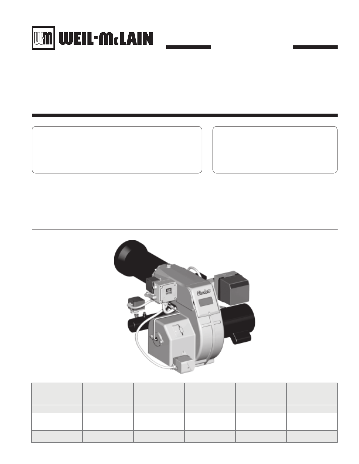
Model CG Figure 1
Beckett
Gas Burners
Models CG10, CG25, CG50
Burner
Model
Number
CG10 1/3 120/60/1 240/60/1 22.0 11.7
CG25 3/4 120/60/1
CG50 2 230/60/1
Motor
Size H.P.
Standard Motor
Electrical
Characteristics
Optional Motor
Electrical
Characteristics
240/60/1,
460/60/3,
575/60/3
460/60/3,
575/60/3
Length
(From Mounting
Flange To Label Area
On Burner Front)
29.2 20.9
29.6 24.4
Part No. 550-142-027/0508
Overall
Width
Page 2
Weil-McLain 88 Water and Steam Boilers — Series 2 — For Gas, Light Oil, & Gas/Light Oil-Fired Burners
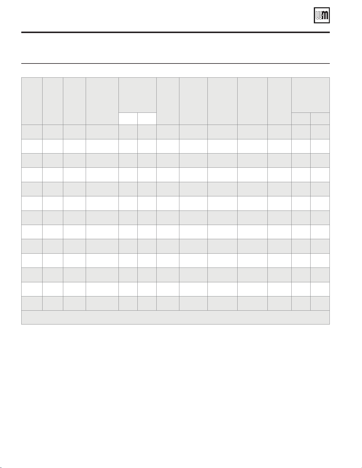
Burner specifications and settings
Burner dataTable 1
Boiler
Model
Number
488R 996 CG10 CG106152 N/A 10/3.5 6 0.50 1/3 2.46 4.30 6.71 14.00
488 1010 CG10 CG106152 N/A 10/3.5 6 0.50 1/3 2.53 4.50 6.71 14.00
588 1357 CG25 CG251258 23 39 1 0.60 3/4 1.90 3.55 5.50 14.00
688 1703 CG25 CG252259 25 48 2 0.70 3/4 2.45 3.70 6.57 14.00
788 2049 CG50 CG501289 14 28 1 0.60 2 2.14 3.10 5.11 14.00
888 2396 CG50 CG502290 14 31 2 0.65 2 2.57 3.05 5.62 14.00
988R 2482 CG50 CG502291 14 34 2 0.60 2 2.44 3.10 5.50 14.00
988 2713 CG50 CG502291 14 34 2 0.60 2 2.92 3.75 5.50 14.00
1088R 2887 CG50 CG503292 17 38 3 0.65 2 1.94 3.00 6.00 14.00
Burner
Input
Gas
Mbh
Burner
Model
Number
Beckett
Burner
Part Number
For Ordering
Approximate
Starting
Air Settings
Low
Fire
High
Fire
Starting
Head
Setting
Positive
Pressure In
Firebox
Inches W.C.
Burner
Motor
3450 Rpm
H.P.
Pressure
Drop
Through
Gas Train
Inches W.C.
Gas
Manifold
Pressure
(High
Fire)
Inches
W.C.
Gas Pressure
Required At
Gas Controls
Inlet
Inches W.C.*
Min Max
1088 3103 CG50 CG503292 17 38 3 0.65 2 2.25 3.65 6.00 14.00
1188 3392 CG50 CG504293 20 50 4 0.70 2 2.65 3.60 6.45 14.00
1288 3753 CG50 CG504294 19 68 4 0.65 2 3.25 4.15 6.36 14.00
1388 4113 CG50 CG505295 24 93 5 0.70 2 2.53 4.00 6.68 14.00
*Gas pressures shown are for standard gas train arrangement. Contact Weil-McLain for alternate gas trains to support other gas pressures.
2 Part No. 550-142-027/0508
Page 3

Burner Specification & Data sheet — Beckett Gas Burners
Burner specifications and settings
Gas train components and flame safeguardsTable 2
Standard Gas Control Components and Sizes in Inches
Boiler
Model
Number
488R-488 1 1 1 1
588 & 688 1-1/4 1-1/4 1-1/4 1-1/4
788-988 1-1/2 1-1/2 1-1/2 1-1/2
1088R-1288 2 2 2 2
1388 2-1/2 2-1/2 2-1/2 2-1/2
Boiler
Model
Number
488R-488 RM7897A -- -- RM7897A -- -- RM7897A -- -588-1388 -- RM7897C RM7840L -- RM7897C RM7840L -- RM7897C RM7840L
OO or LFS LHL MOD OO or LFS LHL MOD OO or LFS LHL MOD
Manual
Hand Valve
(Field Gas Train
Connection)
Flame Safeguard Provided with Listed Control Systems by Code
UL/ CSD1 FM IRI
Additional control suppliers are available
Combination
Diaphragm
Operating Gas Valve
And Regulator
(continued)
Safety
Gas Valve
Manual Checking
Gas Valve
Notes for Table 1 and Table 2
Standard motor voltage is 120/60/1 for CG10, CG25 , and 1.
230/60/1 for CG50.
Direct Spark Ignition is standard on all models.2.
CG10 models are available only as OO (On-Off operation) or 3.
LFS (Low fire start, high fire run. Single position air, adjustable opening gas valve).
CG25 and CG50 are available as: LHL Low-high-low-off 4.
operation. Two position air controlled by linkageless damper
actuator, fixed damper pre-purge.
Must be wired with boiler temperature or pressure control •
switch or operation will be low-high-off.
MOD – On-off operation with proven low fire start and •
full modulating firing conditions with combustion air
control.
Modulation control drives combustion air damper and •
fuel metering valve in response to boiler demand. Fixed
damper pre-purge for RM 7897C.
Open damper pre-purge for RM7840L.•
Burner capacities listed for elevations up to 2,000 feet. For 5.
higher elevations, consult local Weil-McLain distributor/
agent or sales office.
Gas ratings based on natural gas with heating value of 1,000 6.
btu per cubic foot and specific gravity of 0.60.
Boiler-burner unit to be adjusted to achieve +0.10 inches 7.
W.C. pressure at flue collar, resulting in positive pressure in
firebox as listed.
Minimum gas pressures listed are subject to variations due 8.
to job conditions. Gas burners for other gas pressures are
available. Consult local Weil-McLain distributor/agent or
sales office.
Gas manifold pressures shown are for initial start-up. Final 9.
pressure should be determined after checking actual gas flow
and combustion readings.
Combustion Controls:10.
RM7897 flame safeguard control uses ultraviolet elec-a.
tronic flame detector to monitor gas burner flame, and
provides pre-purge programming. “C” models provide
10 second main flame establishing period.
RM7840L flame safeguard control monitors the gas b.
burner flame, provides pre-purge and post-purge programming, provides switching necessary to allow firing
rate motor to be driven to both low fire start and high fire
positions, prevents start-up if preignition interlock circuit
or running interlock circuit does not “prove”, system will
lock out on safety. Ultraviolet sensitive electronic flame
detector is standard.
Burners listed by Underwriters Laboratories, Inc., Canadian 11.
Gas Association, state of Connecticut, Fire Marshal state of
Massachusetts, city of New York MEA, and others.
Special controls can be provided to meet other code require-12.
ments not listed. Consult your local Weil-McLain distributor/
agent or sales office.
3Part No. 550-142-027/0508
Page 4

Weil-McLain 88 Water and Steam Boilers — Series 2 — For Gas, Light Oil, & Gas/Light Oil-Fired Burners
Burner dimensions
Beckett model CG10Figure 2
Burner
Model
Number
Beckett models CG25 and CG50Figure 3
Dimensions, In Inches
A B C D E F G H I J K L
Overall
Width
Square
Flange
Width &
Height
Bolt
Circle
Maximum
Tube O.D.
Centerline
To End Of
Manifold
Tube
Centerline
To Manifold
Centerline
Overall
Length
(Max.)
Burner
Length
Centerline
To Top Of
Burner
Centerline
To Bottom
Of Burner
Centerline
Of Manifold
To End Of
Tube
Insertion
Depth
(Max.)
Pipe
Thread
CG10 11.70 10.0 10.25 4.9 8.1 6.0 26.0 22.0 6.8 8.2 11.0 4.0 1-1/4 NPT
CG25 20.90 12.00 10.25 6.9 9.3 6.8 33.2 29.2 4.1 12.8 17.8 4.0 2 NPT
CG50 24.4 12.00 10.25 7.7 10.5 7.5 33.6 29.6 4.1 14.6 17.4 4.0 2-1/2 NPT
4 Part No. 550-142-027/0508
 Loading...