

Page 1
®
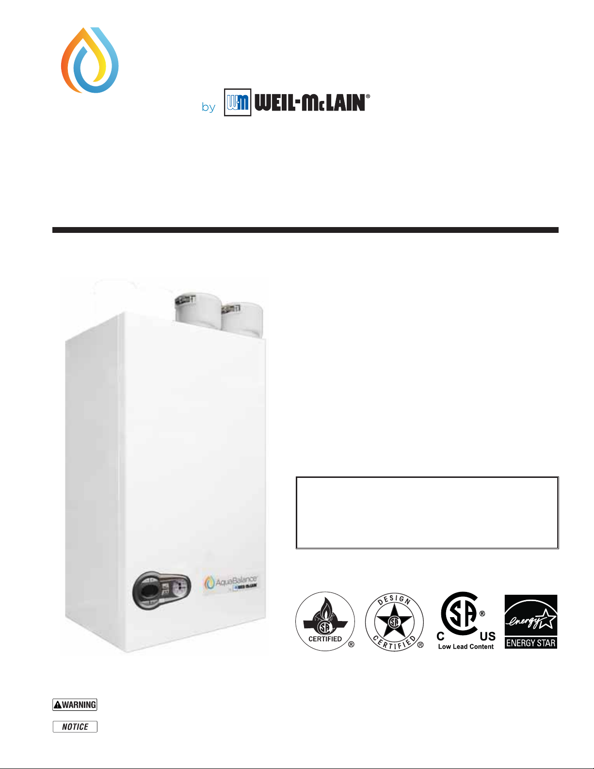
Aqua Balance
80/120/155
Series 2
Wall Mount Gas-Fired
Condensing Boilers – Combi and Heating Only Models
Boiler Manual
• Installation
• Startup
Quick Start Guide
Pages 69 & 70
• Maintenance
• Parts
*
* CSA - Low Lead Content only applies to the Combi model
This manual must only be used by a qualified heating installer/service technician. Failure to comply could result in
severe personal injury, death or substantial property damage.
When calling or writing about the boiler— Please have boiler model number from the boiler rating label.
Part number 550-100-325/0718
Page 2
AquaBalance® SERIES 2 WALL MOUNT GAS-FIRED WATER BOILER — Boiler Manual
Contents Page
1 Please read before proceeding . . . . . . . . . . . . . 3
2 Prepare boiler location . . . . . . . . . . . . . . . . . . 4
3 Prepare boiler . . . . . . . . . . . . . . . . . . . . . . . 6
4 Converting boiler to propane . . . . . . . . . . . . . 10
5 Gas piping — sizing gas lines . . . . . . . . . . . . . 14
6 Venting/air piping — general. . . . . . . . . . . . . . 15
7 Commonwealth of Massachusetts installations . . . 18
8 Vent termination requirements. . . . . . . . . . . . . 19
9 Boiler room air openings. . . . . . . . . . . . . . . . 20
10 DIRECT VENT — Sidewall with separate pipes . . . 21
11 DIRECT VENT — Sidewall concentric . . . . . . . . 23
12 DIRECT VENT — Vertical with separate pipes. . . . 25
13 DIRECT VENT — Vertical concentric. . . . . . . . . 27
14 Concentric termination, typical (sidewall or vertical) . . 29
15 Vent and air piping and boiler connections . . . . . 30
16 Install water piping . . . . . . . . . . . . . . . . . . 33
Domestic Water Piping – Combi Boiler . . . . . . . . . 33
17 Primary/Secondary System Piping . . . . . . . . . . . . 35
System water piping methods . . . . . . . . . . . . . . 35
Expansion Tank Location . . . . . . . . . . . . . . . . 35
Diaphragm- or bladder-type tank: . . . . . . . . . . . . 35
Closed-type expansion tank: . . . . . . . . . . . . . . 37
Install relief valve . . . . . . . . . . . . . . . . . . . . . 38
Zone Valve zoning – primary/secondary . . . . . . . . 39
Circulator zoning – primary/secondary . . . . . . . . . 40
Circulator zoning – Multiple temperature zones with
primary/secondary . . . . . . . . . . . . . . . . . . . . 41
18 Multiple boiler installations . . . . . . . . . . . . . . 42
19 Install condensate line . . . . . . . . . . . . . . . . 45
20 Gas piping . . . . . . . . . . . . . . . . . . . . . . . 46
21 Field wiring. . . . . . . . . . . . . . . . . . . . . . . 48
22 Wiring diagram — AB-80/120C Co mbi Lad der . . . . 50
22 Wiring diagram — AB-80/120C Combi Schematic . . . 51
23 Wiring diagram — AB-80/120H Heating Only Ladder . 52
23 Wiring diagram — AB-80/120H Heating Only Schematic . 53
24 Wiring diagram — AB-155C Combi Ladder . . . . . . . . . 54
24 Wiring diagram — AB-155C Combi Schematic . . . . . . . 55
25 Wiring diagram — AB-155H Heating Only Ladder . . . . . 56
25 Wiring diagram — AB-155H Heating Only Schematic . . . 57
26 Controls and operation . . . . . . . . . . . . . . . . 58
27 DHW Settings (Combi Only) . . . . . . . . . . . . . 63
28 Standard Altitude . . . . . . . . . . . . . . . . . . . 65
28 High Altitude . . . . . . . . . . . . . . . . . . . . . . 66
29 Startup — Quick Start Guide using default settings 69
6WDUWXS²¿QDOFKHFNV . . . . . . . . . . . . . . . . 74
6WDUWXSYHUL¿FDWLRQ . . . . . . . . . . . . . . . . . . 80
32 Annual startup and general maintenance . . . . . . 81
33 Annual startup . . . . . . . . . . . . . . . . . . . . . 82
34 Troubleshooting . . . . . . . . . . . . . . . . . . . . 85
35 Maintenance . . . . . . . . . . . . . . . . . . . . . 107
36 Replacement parts . . . . . . . . . . . . . . . . . 116
37 Connections, Dimensions and Engineering Data . 128
38 Ratings . . . . . . . . . . . . . . . . . . . . . . . . 131
,QVWDOODWLRQDQG6HUYLFH&HUWL¿FDWH. . . . . . . . . 132
2
Hazard definitions
Hazards that will cause severe personal injury, death
or substantial property damage.
Hazards that can cause severe personal injury, death
or substantial property damage.
INSTALLER — Read all instructions before
installing. Read page 3 first. Follow all instructions in proper order to prevent personal injury
or death.
• Consider piping and installation when determining
boiler location.
• Any claims for damage or shortage in shipment
must be filed immediately against the transportation company by the consignee.
Hazards that will or can cause minor personal
injury or property damage.
Special instructions on installation, operation or
maintenance that are important but not related to
personal injury or property damage.
USER — Please read the following. Failure to
comply could result in severe personal injury,
death or substantial property damage.
• This manual is for use only by your qualified
heating installer/service technician.
• Please see the User’s Information Manual for your
reference.
• Have the boiler serviced by a qualified service
technician, at least annually.
Part number 550-100-325/0718
Page 3
AquaBalance® SERIES 2 WALL MOUNT GAS-FIRED WATER BOILER — Boiler Manual
1 Please read before proceeding
Installer— Read all instructions, including this
manual and all other information shipped with the
boiler, before installing. Perform steps in the order
given.
User — This manual is for use only by a qualified
heating installer/service technician. Refer to User’s
Information Manual for your reference.
User — Have this boiler serviced/inspected by a
qualified service technician, at least annually.
Failure to comply with the above could result in severe
personal injury, death or substantial property damage.
If any part of a boiler, burner or its controls has
been sprayed with or submerged under water,
either partially or fully, DO NOT attempt to operate the boiler until the boiler has been either
replaced or completely repaired, inspected, and
you are sure that the boiler and all components
are in good condition and fully reliable.
Otherwise, by operating this boiler, you will cause
a fire or explosion hazard, and an electrical shock
hazard, leading to serious injury, death, or substantial property damage. See the instructions at right.
Failure to adhere to the guidelines below can result in severe personal injury, death or substantial property damage.
When servicing boiler —
• To avoid electric shock, disconnect all
electrical supplies to the boiler before
performing maintenance.
• To avoid severe burns, allow boiler to
cool before performing maintenance.
• This boiler contains ceramic fiber and
fiberglass materials. Refer to the WARN-
ING and instructions on page 82.
Boiler operation —
• Do not block flow of combustion or
ventilation air to boiler.
• Should overheating occur or gas supply
fail to shut off, do not turn off or disconnect electrical supply to pump. Instead,
shut off the gas supply at a location
external to the appliance.
Combustion air —
• DO NOT install combustion air intake
where there is a risk of combustion air
contamination.
Carbon monoxide detector —
• A carbon monoxide detector that is
wired on the same electrical circuit as
the boiler is strongly recommended.
SURGE PROTECTOR —
• Provide surge protection in the boiler
power supply. This will reduce the pos-
sibility of damage to the boiler control.
*
In some locations, a carbon monoxide
detector is required by the law.
Boiler water —
• The heat exchanger is made of stainless
steel, and requires that system water
chemistry be within the limits in this
manual. Use Sentinel X100 inhibitor
in the boiler.
TREATMENT MAY BE NECESSARY
page 71 for details.
• Thoroughly flush the system (
connecting boiler) to remove sediment.
The high-efficiency heat exchanger can
be damaged by build-up or corrosion
due to sediment.
• Do not use petroleum-based cleaning
or sealing compounds in boiler system.
Gaskets and seals in the system may be
damaged. This can result in substantial
property damage.
• Continual fresh make-up water will
reduce boiler life. Mineral buildup in
heat exchanger reduces heat transfer,
overheats the aluminum heat exchanger,
and causes failure. Addition of oxygen
carried in by make-up water can cause
internal corrosion. Leaks in boiler or
piping must be repaired at once to
ADDITIONAL CHEMICAL
Write in the CP number in the space provided on
the Installation certificate on page 132 if not already
shown.
When calling or writing about the boiler— Please
have the boiler model number from the boiler rating
label and the CP number from the boiler jacket.
Consider piping and installation when determining
boiler location.
Any claims for damage or shortage in shipment
must be filed immediately against the transportation
company by the consignee.
Saltwater Damage — The exposure of boiler components to
saltwater can have both immediate and long-term effects. While
the immediate effects of saltwater damage are similar to those of
freshwater (shorting out of electrical components, washing out of
critical lubricants, etc.), The salt and other contaminants left behind
can lead to longer term issues after the water is gone due to the
conductive and corrosive nature of the salt residue. Therefore, WeilMcLain equipment contaminated with saltwater or polluted water
will no longer be covered under warranty and should be replaced.
Electrical Damage — If any electrical component or wiring
came into contact with water, or was suspected to have come into
contact with water, replace the boiler with a new Weil-McLain boiler.
prevent make-up water. Use this boiler
ONLY in a closed-loop system.
• Do not add cold water to a hot boiler.
Thermal shock can cause heat exchanger
to crack.
Freeze protection fluids —
• NEVER use automotive or standard
glycol antifreeze. Use only freeze-protec-
. See
BEFORE
tion fluids made for hydronic systems.
Follow all guidelines given by the antifreeze manufacturer. Thoroughly clean
and flush any replacement boiler system
that has used glycol before installing the
new boiler Use only the products listed
by Weil-McLain for use with this boiler.
See page 117 for details.
Frozen Water Damage
Hazard
Residences or buildings that are unattended in severely cold weather, boiler
system components failures, power outages, or other electrical system failures
could result in frozen plumbing and water
damage in a matter of hours. For your
protection, take preventative actions such
as having a security system installed that
operates during power outages, senses low
temperature, and initiates an effective action. Consult with your boiler contractor
or a home security agency.
Commonwealth of
Massachusetts
Part number 550-100-325/0718
When the boiler is installed within the Commonwealth of Massachusetts:
• This product must be installed by a licensed plumber or gas fitter.
• If antifreeze is used, a reduced pressure back-flow preventer device shall be used.
• Sidewall vent air installations — see instruction on page 18.
3
Page 4

AquaBalance® SERIES 2 WALL MOUNT GAS-FIRED WATER BOILER — Boiler Manual
2 Prepare boiler location
Codes and Checklists:
Installations must comply with:
• Local, state, provincial, and national codes, laws, regulations and
ordinances.
• National Fuel Gas Code, ANSI Z223.1/NFPA 54 - latest edition.
• National Electrical Code ANSI/NFPA 70 – latest edition. Electrical
installation and grounding must be in accordance with CSA C22.1,
Part 1, Canadian Electrical Code, and/or local codes.
• For Canada only: CAN/CSA B149.1, Natural Gas and Propane
Installation Code, and any local codes.
• Where required by the authority having jurisdiction, the installation must conform to the Standard for Controls and Safety Devices
for Automatically Fired Boilers, ANSI/ASME CSD-1.
Certification
The boiler gas manifold and controls met safe lighting
and other performance criteria when boiler underwent
tests specified in ANSI Z21.13 — latest edition.
Flooring
1. The boiler must not be installed on carpeting.
Do not install boiler on carpeting even if foundation
is used. Fire can result, causing severe personal injury,
death or substantial property damage.
Before locating the boiler:
1. Wall construction — Make sure the wall construction is
suitable to carry the weight of the boiler and components.
See page 7 for instructions.
2. The boiler is suitable for INDOOR installation
3. Check for nearby connection to:
• System water piping • Venting connections
• Gas supply piping • Electrical power
• Condensate drain
4. Check area around boiler. Remove any combustible materials,
gasoline and other flammable liquids.
Failure to keep boiler area clear and free of combustible
materials, gasoline and other flammable liquids and
vapors can result in severe personal injury, death or
substantial property damage.
5. The boiler must be installed so that gas control system components
are protected from dripping or spraying water or rain during
operation or service.
6. If new boiler will replace existing boiler, check for and correct
system problems, such as:
• Sediment or corrosion in system piping — clean and flush piping
BEFORE connecting the new boiler. See page 71.
• System leaks causing oxygen corrosion or heat exchanger cracks
from hard water deposits.
• Incorrectly-sized expansion tank.
• Lack of freeze protection in boiler water causing system and
boiler to freeze and leak.
only.
Residential garage installation
Precautions
1. Take the following special precautions when installing the boiler in
a residential garage. If the boiler is located in a residential garage:
• Mount the boiler with its burner and igniter are at least
18 inches above the floor. Follow the National Fuel Gas Code,
ANSI Z223.1 for U. S. installations, or Natural Gas and Pro-
pane Installation Code, CSA B149.1 and B149.2 for
Canadian installations.
• Locate or protect the boiler so it cannot be damaged
by a moving vehicle.
• Ensure that the installation complies with all applicable
codes.
• Prevent boiler water and condensate from freezing.
Provide air openings to room
Boiler alone in boiler room
1. No air ventilation openings into boiler room are needed if
clearances around boiler are at least equal to the SERVICE
clearances shown in Figure 1, page 5.
2. For spaces that DO NOT supply the minimum service clearances, provide two openings as shown in Figure 1, page 5.
Each opening must provide 1 square inch free area per
1,000 Btuh of boiler input.
Boiler in same space with other gas or
oil-fired appliances
1. Follow the sizing requirements shown in Figure 23, page 20.
The space must be provided with combustion/
ventilation air openings correctly sized for all
appliances located in the same space as the
boiler.
Reinstall boiler jacket door after servicing. The
boiler jacket door must be securely fastened
to the boiler to prevent boiler from drawing
air from inside the boiler room. This is particularly important if the boiler is located in
the same room as other appliances.
Failure to comply with the above warnings
could result in severe personal injury, death
or substantial property damage.
Vent and air piping
1. The boiler requires a special vent system, designed for
pressurized venting. Boilers are rated ANSI Z21.13
Direct Vent (pressurized vent, likely to condense in the
vent). See instructions beginning on page 15.
2. You must also install air piping from outside to the
boiler air intake adapter. The resultant installation is
categorized as direct vent (sealed combustion). Note
prevention of combustion air contamination on page 6
when considering vent/air termination.
3. Vent and air must terminate near one another unless
otherwise specified in this manual. Vent and air piping
may be routed vertically through the roof or out a side
wall, following the options give in this manual. You may
use any of the vent/air piping methods covered in this
manual. Do not attempt to install the boiler using any
other means.
4. Be sure to locate the boiler such that the vent and air
piping can be routed through the building and properly
terminated. The vent/air piping lengths, routing and
termination method must all comply with the methods
and limits in instructions beginning on page 15.
4
Part number 550-100-325/0718
Page 5
AquaBalance® SERIES 2 WALL MOUNT GAS-FIRED WATER BOILER — Boiler Manual
2 Prepare boiler location continued
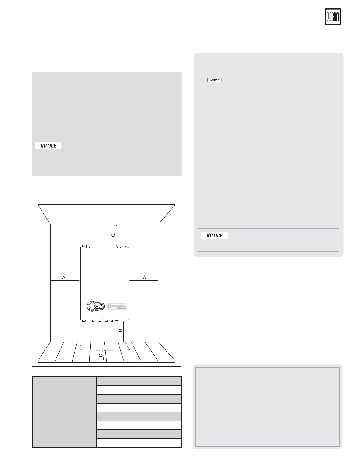
Clearances
Provide clearances from
combustible materials — REQUIRED
1. See Figure 1 for REQUIRED minimum clearances. ALL
installation must provide at least these minimums.
2. Hot water pipes — at least
3. Vent pipe — at least 3/16” from combustible materials.
4. See Figure 1 for service clearance minimums.
If the unit is enclosed in a cabinet or mounted
alongside, a space must be provided for removing the casing and for normal maintenance
operations. The minimum measurements to be
respected are given in Figure 1.
Figure 1 REQUIRED minimum clearances
all dimensions are in inches)
(
1/2” from combustible materials.
A Provide combustion air/ventilation openings per Figure 23, page 20
or as otherwise directed in this manual or by applicable codes.
If the installation does not provide the minimum clearances,
then the enclosure MUST HAVE air openings located per Figure 2,
above. Each of these air openings must have free area of at least
1 square inch per 1,000 MBH of boiler input.
B Left side clearance to combustibles = 1.0 inches minimum
C Top of boiler clearance to combustibles = 12.0 inches minimum
D Right side clearance to combustibles = 1.0 inches minimum
E Bottom of boiler clearance to combustibles = 12 inches minimum
(must be 18 inches above floor for garage installations)
F Clearance in front of the boiler = 12.0 inches, but 36 inches mini-
mum required for service
H Vent pipe must be minimum 3/16 inch from combustibles. Opening
in combustible wall, floor, ceiling or roof must be 3/8” larger than
flue pipe diameter, fitted with galvanized steel thimble, or larger if
required by codes or as specified by vent pipe manufacturer.
ADDITIONAL service clearance may be
needed, depending on how piping is routed
to the boiler.
Minimum
required
for
Combustion
Recommended
for
Service
A Minimum 1.00”
B Minimum 12.00”
C Minimum 12.00”
D Minimum 12.00”
A Minimum 36.00”
B Minimum 36.00”
C Minimum 24.00”
D Minimum 36.00”
Provide clearances for service
access — RECOMMENDED
1. See Figure 1, for recommended service clearances.
2. If you do not provide minimum service clearances shown, it
might not be possible to service the boiler without removing
it from the space.
3. Clearance D, Figure 1 allows for the installation of piping as
shown in Figure 5, page 9, plus a union, close nipple and
elbow.
A Provide combustion air/ventilation openings per Figure 23, page 20 or
as otherwise directed in this manual or by applicable codes. NOTE: If
the installation does not provide the minimum clearances in this illustration, then the enclosure must have air openings located and sized
per Figure 1.
B Left side service clearance = 36 inches minimum
C Service clearance above top of boiler = 24 inches minimum
D Right side service clearance = 24 inches minimum
E Service clearance below the boiler = 36 inches minimum
F Service clearance in front of the boiler = 36 inches minimum
Part number 550-100-325/0718
5
Page 6
AquaBalance® SERIES 2 WALL MOUNT GAS-FIRED WATER BOILER — Boiler Manual
2 Prepare boiler location
Air contamination
Please review the following information on potential combustion
air contamination problems.
See Table 1 for products and areas which may cause contaminated
combustion air.
To prevent potential of severe personal injury or
death, check for products or areas listed below before installing boiler. If any of these contaminants
are found:
• remove contaminants permanently.
— OR —
• isolate boiler and provide outside combustion air.
See national, provincial or local codes for further
information.
Table 1
Products to avoid
Spray cans containing chloro/fluorocarbons
Permanent wave solutions
Chlorinated waxes/cleaners
Chlorine-based swimming pool chemicals
Calcium chloride used for thawing
Sodium chloride used for water softening
Refrigerant leaks
Paint or varnish removers
Hydrochloric acid/muriatic acid
Cements and glues
Antistatic fabric softeners used in clothes dryers
Chlorine-type bleaches, detergents, and cleaning solvents found in
household laundry rooms
Adhesives used to fasten building products and other similar
products
Excessive dust and dirt
Areas likely to have contaminants
Dry cleaning/laundry areas and establishments
Swimming pools
Metal fabrication plants
Beauty shops
Refrigeration repair shops
Photo processing plants
Auto body shops
Plastic manufacturing plants
Furniture refinishing areas and establishments
New building construction
Remodeling areas
Garages with workshops
Corrosive contaminants and likely locations
continued
You must pipe combustion air to the boiler
air intake
.
Install air inlet piping for the boiler as described in
this manual.
The air termination fitting must be installed with
the clearances and geometry relative to the vent
outlet depicted in this manual to ensure that flue
products do not enter the air intake.
Ensure that the combustion air will not contain
any of the contaminants in Table 1. Do not pipe
combustion air near a swimming pool, for example.
Avoid areas subject to exhaust fumes from laundry
facilities. These areas will always contain contaminants.
Contaminated combustion air will damage the
boiler, resulting in possible severe personal injury,
death or substantial property damage.
3 Prepare boiler
Remove boiler from carton
The boiler is heavy. Use caution not to drop the
boiler or cause bodily injury while lifting and handling. Verify that the boiler is securely attached to
prevent possibility of boiler falling after installation.
Do not drop boiler or bump jacket on floor or pallet.
Damage to boiler can result.
Cold weather handling — If boiler has been stored
in a very cold location (below 0°F) before installation, handle with care until the plastic components
come to room temperature.
1. The boiler is generally easier to handle and maneuver after
removing the shipping container.
Leave the boiler resting on the styrofoam protective base
2.
and bottom cardboard cap, until ready to place on the wall.
The boiler is arranged and designed for wall
mounting and comes standard with a hanging
bracket. The wall fixture must ensure stable and
effective support for the boiler.
6
Part number 550-100-325/0718
Page 7
AquaBalance® SERIES 2 WALL MOUNT GAS-FIRED WATER BOILER — Boiler Manual
3 Prepare boiler continued
Wall-mounting requirements
DO NOT attempt to attach the wall mount bracket
using anchors or any means other than directly
securing to the wall studs (or equivalent wood
structure if studs are not on 16-inch centers).
The wall must be vertically plumb and capable
of carrying the weight of the boiler and any attached piping components
The operating weight for wall-mountable boiler is:
1. Stud spacing: Bracket holes are spaced for studs on 16-inch
centers. For other stud spacing, provide secure, solid mounting
surface on which to attach the boiler wall-mounting bracket.
2. Wood stud wall: Install bracket with lag screws (3/8” x 3”)
included in kit, only into the studs.
3. Metal stud wall: Secure bracket and spacer board to studs
with 3/16-inch toggle bolts and 3/16-inch flat washers (not
included with kit).
4. Concrete or block wall: Secure wall bracket with approved
bolts for that application.
5. If the mounting wall has exposed studs, installer must provide
a backer board to mount boiler. Boiler cannot be leveled
without a backing surface.
6. Mount the boiler on the wall following these instructions.
The boiler mounting studs must engage with the wall-mount
bracket. Make sure the bracket is not just resting on the edge
of the mounting stud or washer. Perform all procedures given
in the Boiler Manual on previous pages before mounting
the boiler.
AB-80: 70 pounds
AB-120: 80 pounds
AB-155
Failure to comply with above and the procedure
given below could result in severe personal injury,
death or substantial property damage.
Verify that the studs are suitable for carrying a wallmounted load. Some metal studs are not designed
for this purpose.
: 87 pounds
.
Install the wall-mount bracket
1. Locate the studs — must be on 16-inch centers. See previous instructions if studs are not on 16-inch centers.
2. Place the wall-mount bracket Figure 3, below on the wall,
using a level to align correctly.
3. Place the wall-mount bracket so the mounting slots are
centered over the studs.
4. Level the bracket and trace the outline of the screw slots
with a pencil.
Figure 3 Wall mount bracket
Lag bolt mounting locations
5. Remove the mounting bracket and drill holes 1/4” diameter
by 3 inches deep, centered on the screw slot outlines. (For
metal stud walls, using 3/16” toggle bolts, drill required
clearance holes.)
6. Position the wall-mount bracket on the wall. Insert and
loosely tighten the two (2) lag screws (or toggle bolts for
metal studs).
Figure 4 Wall mount bracket tabs bend over boiler to
secure boiler in place
Bend tabs after installation
Install rubber bumpers to back of boiler
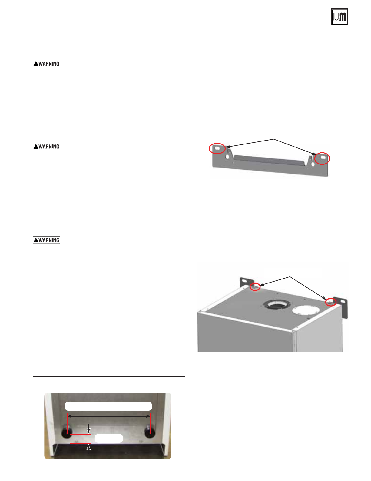
1. Remove supplied rubber bumpers from plastic bag and measure across 14 inches, and up 2 inches from the back of the
boiler bottom edge. Mark these two locations, and peel off
adhesive protection from the rubber bumpers, and mount
the two according to the directions in Figure 2.
2. DO NOT drill holes to mount the rubber bumpers
Figure 2 Addition of rubber bumper for wall mounting
14 inches-center to center of rubber
2 inches
Part number 550-100-325/0718
7. Level the wall-mounting bracket. Then tighten lag screws
securely. For drywall or plaster lathe installations, avoid
tightening so much that the bracket digs into the wall
surface.
Place boiler on bracket
1. The wall-mount bracket must be installed before mounting
the boiler.
2. After installing the boiler on the mounting bracket, bend
down the two (2) tabs in order to secure boiler in place,
see Figure 4.
7
Page 8

AquaBalance® SERIES 2 WALL MOUNT GAS-FIRED WATER BOILER — Boiler Manual
3 Prepare boiler continued
Hydrostatic pressure test
DO NOT install a relief valve with a pres-
sure higher than 30 PSIG. This is the maximum allowable relief valve setting for the
boiler.
Failure to comply could prevent the relief
valve from operating as needed, resulting
in possibility of severe personal injury,
death or substantial property damage.
Use two wrenches when tightening any pipe
connection to the boiler
boiler pipes from turning could damage pipes
or heat exchanger, resulting in possible severe
personal injury, death or substantial property
damage.
Pressure test the boiler before permanently attaching water or
gas piping or electrical supply.
. Failure to prevent the
Install pipe fittings for relief valve
and P/T gauge
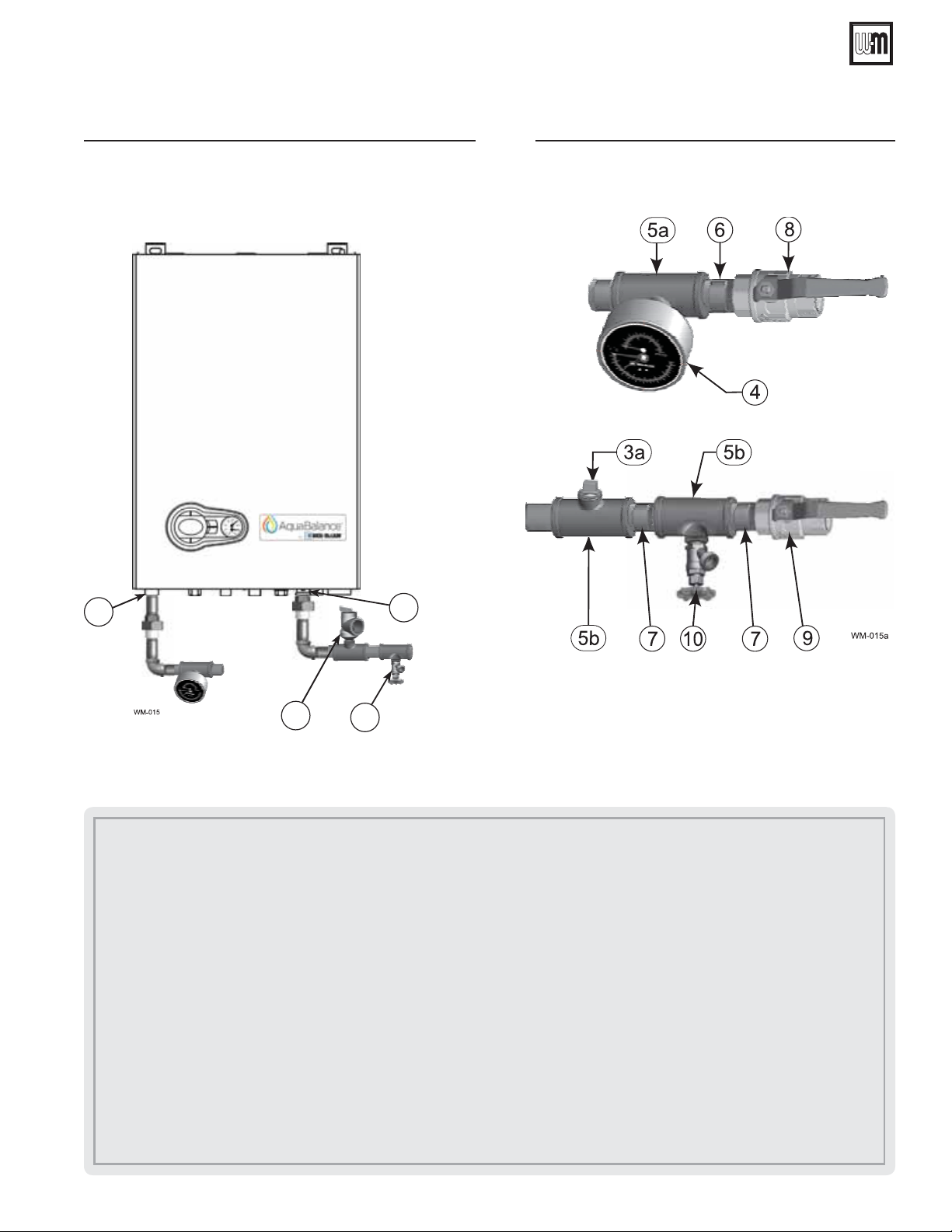
1. Install the reducing tees, and close nipples, field supplied,
located and oriented as shown in Figure 5, page 9. Apply
pipe dope to all fittings sparingly.
DO NOT install the relief valve until after the
hydrostatic test
plug in the relief valve location as directed in these
instructions. The plug must be removed after the
test.
Connect the relief valve ONLY on the BOILER
RETURN OUTLET, NOT
nect the relief valve only as shown in this manual.
Ensure relief valve is located above heat exchanger.
Failure to comply with the above could prevent
the relief valve from operating as needed, resulting
in possibility of severe personal injury, death or
substantial property damage.
. Temporarily install a ¾” pipe
the boiler supply. Con-
Fill and pressure test
1. See Figure 5, page 9, for use with the following instructions.
2. CLOSE the boiler drain valve (item 10). Connect a hose to
fresh water supply and to the drain valve.
3. Place a bucket under the ends of the isolation valves
(item 8 and 9) to catch water drippings.
4. CLOSE isolation valve item 9, then crack open the valve
slightly. Leave top isolation valve item 8 open.
5. Slowly open the boiler drain valve (item 10) and fresh water
supply to fill boiler with water. The boiler and piping will
fill quickly because of the low water content.
6. When water begins to flow from bottom isolation valve
(item 9), close the valve.
7. Continue filling until water flows from top isolation valve
(item 8), then close the valve.
8. When pressure on the pressure/temperature gauge (item
4) reaches at least 45 PSIG, but no higher than 55 PSIG,
CLOSE the boiler drain valve (item 10).
9. Hold at test pressure for 10 minutes.
Do not leave boiler unattended. A cold water fill
could expand and cause excessive pressure, resulting in severe personal injury, death or substantial
property damage.
10. Make sure constant gauge pressure has been maintained
throughout test. Check for leaks. Repair if found.
Leaks must be repaired at once. Failure to
do so can damage boiler, resulting in substantial
property damage.
Do not use petroleum-based cleaning or sealing
compounds in boiler system. Gaskets and seals
in the system may be damaged. This can result in
substantial property damage.
2. Install the test pressure/temperature gauge (field supplied)
to the reducing tee as shown in Figure 6, page 9.
Install fittings and valves required for
hydrostatic testing (supplied by installer)
1. The following piping components (supplied by installer)
are required for the test configuration:
a. Two shut-off valves - (1”NPT on the 80/120 boilers,
1
-1/4”NPT on the 155 boiler).
b. Two close nipples - (1”NPT on the 80/120 boilers,
1
-1/4”NPT on the 155 boiler).
c. ¾” NPT pipe plug.
d. Pressure/temperature gauge.
e. ¾” NPT boiler drain valve.
2.
TEMPORARILY insert a ¾” NPT pipe plug in the relief valve
tapping. After the hydrostatic test, this plug must be removed
and the relief valve must be installed.
8
Drain and remove fittings
1. Disconnect fill water hose from water source.
2. Drain boiler through drain valve
Use caution when releasing pressure from the boiler.
Rapid water flow could cause injury.
3. Remove hose after draining.
4. Remove nipples and valves unless they will remain for use in
the system piping.
5. Remove plug and install relief valve as specified in the following WARNING.
Remove plug from relief valve street elbow. Install
the relief valve in the ¾” street. See page 38 to install
relief valve discharge piping. Failure to install the
boiler relief valve could result in severe personal
injury, death or substantial property damage.
(item 10).
Part number 550-100-325/0718
Page 9
AquaBalance® SERIES 2 WALL MOUNT GAS-FIRED WATER BOILER — Boiler Manual
3 Prepare boiler continued
Figure 5 Install pipe fittings for relief valve and pressure/
temperature gauge —
valve until AFTER hydrostatic testing
legend below) (Combi boiler shown)
DO NOT mount relief
(see
Figure 6 Install piping components required for
hydrostatic test (
see legend below)
1
2
Boiler Return
3
10
(inlet)
Boiler Supply
(outlet)
1. Boiler Supply (outlet) connection, (male, 1” NPT on the 80/120 boilers, 1” NPT on the 155 boiler).
2. Boiler Return (inlet) connection, (male, 1” NPT on the 80/120 boilers, 1” NPT on the 155 boiler).
Recommend Near Boiler Piping to be 1-1/4” NPT or larger for the 155 boiler. Bushing 1” x 1-1/4” NPT at Supply (outlet) and Re-
turn (inlet) not shown.
3. Boiler relief valve, shipped loose with boiler — DO NOT mount relief valve until AFTER hydrostatic testing.
3a. TEMPORARILY ONLY — Insert a ¾” NPT plug in the relief valve tapping of the reducing tee. This MUST BE REMOVED
after the test and the relief valve mounted here.
4. Pressure/temperature gauge,
5a. Reducing tee, 1” x 1” x ¼” on
5b. Tee, NPT, 1” x 1” x ¾” on
6. Nipple, NPT, 1” x close on
7. Nipple, NPT, 1” x close on
8. Isolation valve on supply connection,
9. Isolation valve on return connection, (field supplied) by installer (1” NPT on the 80/120 boilers, 1-1/4” NPT on the 155 boiler).
10. ¾” NPT boiler drain valve, (field supplied) by installer — after hydrostatic testing, move drain valve to lowest point on the return piping
if not already there.
(field supplied by installer)
(field supplied) by installer, (Optional – can use boiler gauge).
the 80/120 boilers, NPT, 1-1/4” x 1-1/4” x ¼” on the 155 boiler (field supplied) by installer .
the 80/120 boilers, 1-1/4” x 1-1/4” x ¾” on the 155 boiler (field supplied) by installer.
the 80/120 boilers, NPT, 1-1/4” x close on the 155 boiler (field supplied) by installer.
the 80/120 boilers, NPT, 1-1/4” x close on the 155 boiler (field supplied) by installer.
(field supplied) by installer (1” NPT on the 80/120 boilers, 1-1/4” NPT on the 155 boiler).
Part number 550-100-325/0718
9
Page 10
AquaBalance® SERIES 2 WALL MOUNT GAS-FIRED WATER BOILER — Boiler Manual
4 Converting boiler to propane
Prepare boiler for propane (if required)
AquaBalance®
80/120/155
Propane operation
ALL boilers must be converted for pro-
pane operation.
Converting an existing natural gas-fired
boiler for propane —
For a boiler already
installed, you must turn off gas supply, turn off
power and allow boiler to cool before proceeding. You must also completely test the boiler after
conversion to verify performance and start up the
boiler following instructions beginning on page 75
of this manual.
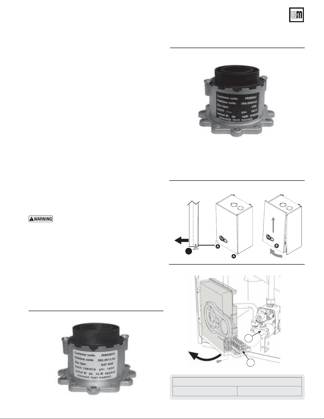
Verify Conversion kit—See Figure 7.
LP gas venturi will have a black label and will be
clearly labeled “LPG”.
Natural gas venturi will have a white label and
will be clearly labeled “NAT GAS”.
Failure to comply could result in severe personal
injury, death or substantial property damage.
This conversion kit shall be installed by a qualified
service agency in accordance with the
manufacturer’s instructions and all applicable codes
and requirements of the authority having jurisdiction.
If the information in these instructions is not followed
exactly, a fire, an explosion or production of carbon
monoxide may result causing property damage,
personal injury or loss of life. The qualified service
agency is responsible for the proper installation of this
kit. The installation is not proper and complete until
the operation of the converted appliance is checked as
specified in the manufacturer’s instructions supplied
with the kit.
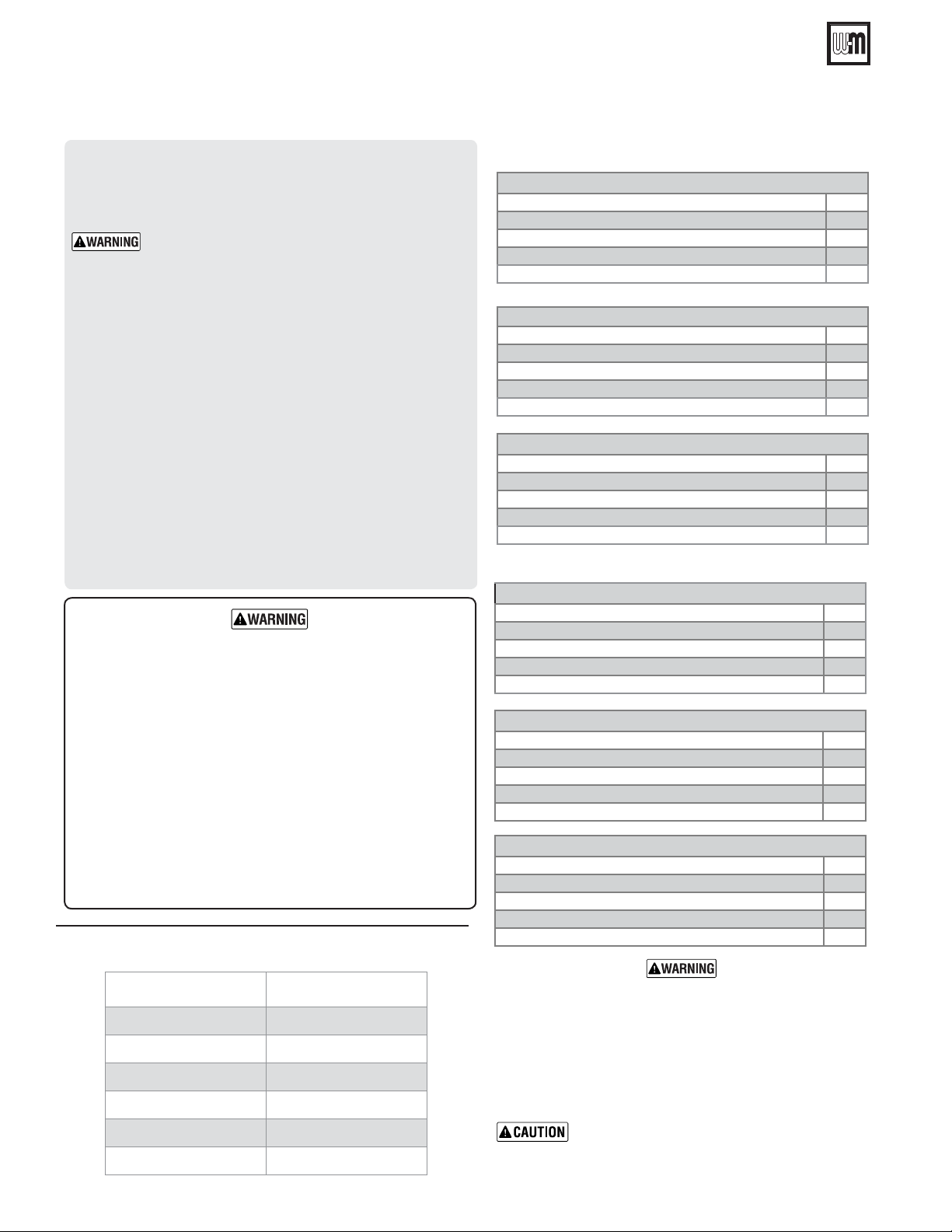
Figure 7 Natural and Liquefied Petroleum (Propane) gas
conversion kits
Natural to LP Conversion Kit Part Numbers
AB-80 LP P/N 640-000-024 NG to Propane Gas Conv. Kit contents:
Venturi - 10.6 GPL
Gasket Nitrile Rubber 167 x 63.5X3.53 NBR
Label Gas Conversion
Label AB-80 Rating Plate Conversion LP
Instructions Conversion Nat to LP Gas
AB-120 LP P/N 640-000-025 NG to Propane Gas Conv. Kit contents:
Venturi - 12.6 GPL
Gasket Nitrile Rubber 167 x 63.5X3.53 NBR
Label Gas Conversion
Label AB-120 Rating Plate Conversion LP
Instructions Conversion Nat to LP Gas
AB-155 LP P/N 640-000-133 NG to Propane Gas Conv. Kit contents:
Venturi Gasket Nitrile Rubber 167 x 63.5X3.53 NBR
Label Gas Conversion
Label AB-155 Rating Plate Conversion LP
Instructions Conversion Nat to LP Gas
1
1
1
1
1
1
1
1
1
1
1
1
1
1
1
LP to Natural Conversion Kit Part Numbers
AB-80 NG P/N 640-000-022 LP to Natural Gas Conv. Kit contents:
Venturi - Natural Gas 10.6m
Gasket Nitrile Rubber 167 x 63.5X3.53 NBR
Label Gas Conversion
Label AB-80 Rating Plate Conversion NG
Instructions Conversion LP to Natural Gas
AB-120 NG P/N 640-000-023 LP to Natural Gas Conv. Kit contents:
Venturi - Natural Gas 12.6m
Gasket Nitrile Rubber 167 x 63.5X3.53 NBR
Label Gas Conversion
Label AB-120 Rating Plate Conversion NG 1
Instructions Conversion LP to Natural Gas 1
AB-155 NG P/N 640-000-082 LP to Natural Gas Conv. Kit contents:
Venturi - Natural Gas 16.6m
Gasket Nitrile Rubber 167 x 63.5X3.53 NBR
Label Gas Conversion
Label AB-155 Rating Plate Conversion NG 1
Instructions Conversion LP to Natural Gas 1
1
1
1
1
1
1
1
1
1
1
1
10
Boiler Model Kit Part Number
AB-80 NG
AB-80 LP
AB-120 NG
AB-120 LP
AB-155 NG
AB-155 LP
640-000-022
640-000-024
640-000-023
640-000-025
640-000-082
640-000-133
• Follow all instructions in proper order.
• Do not tamper with venturi. DO NOT change or modify
venturi in any way.
• Do not leave an uninstalled venturi in the building.
• Caution the gas supply shall be shut off prior to disconnecting the electrical power, before proceeding with the
conversion.
Label all wires prior to disconnection when
servicing controls. Wiring errors can cause
improper and dangerous operation.
Part number 550-100-325/0718
Page 11
AquaBalance® SERIES 2 WALL MOUNT GAS-FIRED WATER BOILER — Boiler Manual
4 Converting boiler to propane continued
Pipe sizing for propane gas
1. Contact propane gas supplier to size piping, tank and install
a 100% lockup gas pressure regulator, or to verify size and
condition of existing piping and equipment.
Natural and Propane supply pressure
requirements
Adjust propane supply regulator provided by gas supplier for 13”
w.c. maximum pressure.
For natural gas or propane, the pressure required at gas valve
inlet pressure port (verify minimum gas pressure when all gas
appliances are in operation):
a. Maximum: 13” w.c. with no flow (lockup) or with boiler on.
b. Minimum: 3.5” w.c. gas pressure, with gas flowing (verify
during boiler startup, while boiler is at high fire).
c. Nominal gas pressure: 11.0” w.c.
2. Install 100% lockup gas pressure regulator in supply
line if inlet pressure can exceed 13” w.c. at any time.
Adjust lockup regulator for 13” w.c. maximum.
3. After connecting propane gas line to boiler, and BEFORE
operating, check gas pressure. If gas pressure is not in the
range above, close manual gas valve and contact gas supplier
to correct the problem before attempting to start or operate
the boiler.
Figure 9 Liquefied Petroleum (propane) gas venturi label
information
Front panel removal
1. Remove two (2) A screws on the bottom flange of front panel,
out and lift up to remove the front panel.
2. Remove the one (1) screw holding control module in place
Figure 11, rotate the control module.
Figure 10 Removing front panel
Installing venturi —
If boiler is already installed — You must turn off
electrical supply to the boiler and close the external
manual gas shut-off valve to isolate the boiler during
conversion. Allow the boiler to cool if it has been
operating.
Following conversion of an installed boiler, follow
all instructions in this manual to start up the boiler
and verify operation of the boiler and all system
components.
Verify proper venturi for gas type
The venturi(s) provided with the kit(s) are permanently marked
on labels to indicate gas type “NAT GAS” Natural gas or “LPG”
for Liquefied petroleum (propane) gas and supplier part number.
See Figure 7, page 10 for kit contents.
Figure 8 Natural gas venturi label information
A
Figure 11
Moving control module for access to gas valve
2
Part number 550-100-325/0718
1
LEGEND for Figure 12
1 Control module 2 Gas valve
11
Page 12
AquaBalance® SERIES 2 WALL MOUNT GAS-FIRED WATER BOILER — Boiler Manual
4 Converting boiler to propane continued
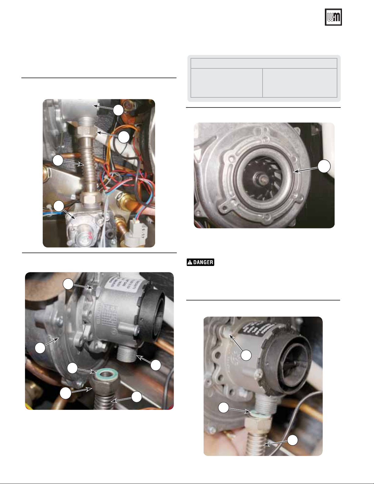
3. Loosen the bottom swivel nut of gas pipe and unscrew the
top swivel nut “A” Figure 12, Item 3 from the gas valve venturi
Figure 12, Item 6.
Figure 12 Loosen fittings of gas pipe (Control module
removed for clarity)
6
A
3
2
LEGEND for Figures 13, 14, 15. 16 and 17
1 Control panel (page 13)
2 Gas valve (page 14)
3 Gas pipe
4 Washer
Figure 14
Insure “O” ring is in place
5 Hex head screws
6 Gas valve venturi
7 “O” Ring
8 Blower
7
Figure 13 Gas valve venturi replacement for propane
conversion
5
8
4
A
4. Remove three (3) Hex head screws holding the venturi,
Item 5 in place, remove venturi, replace with new propane
venturi from kit. Verify the venturi label information
matches the boiler size AB-80/120/155. (Propane venturi
has black label), ensure Item 7, venturi “O” ring is in place
(see Figure 14), re-insert three (3) Hex head screws to
hold new venturi, tighten to hold securely in place.
3
6
5. Reassemble gas pipe and new washer to the venturi fitting,
re-connect nut “A” and gas pipe “Item 3” to venturi and
check the seal of the connection.
Inspect the gas pipe fitting connections on
the gas valve and new venturi (Item 3, Figure 12, page 12) check the seal of the connections. Failure to comply will cause a gas leak,
resulting in severe personal injury or death.
Figure 15
New
LP venturi installed to blower
5
4
3
12
Part number 550-100-325/0718
Page 13
AquaBalance® SERIES 2 WALL MOUNT GAS-FIRED WATER BOILER — Boiler Manual
4 Converting boiler to propane continued
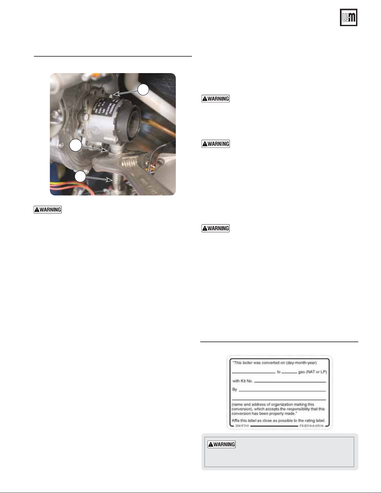
Figure 16 Gas pipe re-assembled to LP venturi fitting
5
A
3
Do not check for gas leaks with an open flame —
use bubble test. Failure to use bubble test or check
for gas leaks can cause severe personal injury,
death or substantial property damage.
6. Reinstall control module, reinstall screw to hold control
module securely in place
7. Reinstall jacket door, and secure with two (2) screws.
Mandatory control changes for fuel
conversion - Perform at start-up final checks
8. Adjust parameter for the type of gas:
a. Put the boiler in standby mode.
b. Press the DHW buttons details 1 and 2 - Figure 76, page 58
for 10 seconds: the display shows “b01“ flashing.
c. Press the DHW buttons Figure 76, page 58 details 1 and 2
- to set parameter 00 (for use with natural gas) or 01
(for use with LP).
d. Press the Heating (+) button to scroll to Parameter “b04”.
e. Press DHW (-) to reduce the Maximum Blower
see Figure 124, page 97.
f. Press the (+) button to scroll to Parameter “b05”.
g. Repeat Step “e” above according to your boiler size.
h. Press the Heating (+) button to scroll to Parameter
“b06”.
i. Press DHW (-) to reduce the Minimum Fan Speed,
see Figure 124, page 97:
j. Press the DHW buttons details 1 and 2 -
Figure 76, page 58 for 10 seconds.
k. The boiler will return to standby mode.
9. Turn on gas by opening gas valve, check for leaks and con-
tinue boiler start up and adjustments, staring on page 78.
10. Test ignition system safety shutoff, see page 79.
11. In USA Input rates are derated 4% for each 1000 ft. above
sea level, beyond 2000 ft. in accordance with National Fuel
Gas Code, ANSI Z223.1/NFPA 54 - latest edition, and/or
the Natural Gas and Propane Installation Code, CAN/CSA
B149.1.
Part number 550-100-325/0718
12. Using a combustion analyzer insert probe into the flue
test point, check that the CO
the boiler operating at max. and min. firing rate, matches
that given in the technical data Figure 103, page 78 or Fig-
ure 106, page 79, for the corresponding type of gas.
DO NOT ATTEMPT TO MEASURE VALVE
OUTLET PRESSURE. The valve could be
damaged by manometer fluid contamination.
Failure to comply could result in severe personal
injury, death or substantial property damage.
content in the exhaust, with
2
Perform Boiler Manual start-up
Follow all instructions in Boiler Manual to start-up
the boiler after converting for propane. Because the
boiler has been changed, you must verify correct
operation, including checking combustion with
test instruments both at high fire and low fire as
described in the Boiler Manual, pages 77, 78 & 79.
Check the correct ignition sequence of the boiler
after the conversion, as in page 86.
Failure to comply could result in severe personal
injury, death or substantial property damage.
Reinstall boiler jacket front door
Replace boiler jacket front door after servicing. The
boiler front door must be securely fastened to the
boiler frame to prevent boiler from drawing air
from inside the boiler room. This is particularly
important if the boiler is located in the same
room as other appliances. Failure to keep the door
securely fastened could result in severe personal
injury or death.
Apply installer conversion label
1. Converting to propane firing: After installation is complete,
attach the propane conversion label (from kit) next to the
boiler rating label.
2. Contractor/installer is responsible for completing the information required on label (provided in kit) and attaching
installer conversion label next to the boiler rating label.
Figure 17 Installer conversion label
The jacket door must be in place during
operation.
the jacket door removed except for inspection
and testing as directed in this manual.
DO NOT operate the boiler with
13
Page 14
AquaBalance® SERIES 2 WALL MOUNT GAS-FIRED WATER BOILER — Boiler Manual
5 Gas piping — sizing gas lines
Boiler gas connection is ½” NPT for 80/120 boil-
ers and ¾” NPT for 155 boilers. Size gas lines large
enough to provide gas to all connected appliances.
Natural Gas:
Pipe sizing for natural gas
1. Size gas piping from meter outlet to entrance of boiler in
accordance with Figure 18 and Figure 19.
2. Use total input of all connected appliances. Divide total input
in Btuh by 1,000 to obtain cubic feet per hour of natural gas.
a. Pipe lengths in Figure 18 are equivalent length of straight
pipe. Convert pipe fittings to equivalent lengths using
data from Figure 19.
b. Figure 18 is only for natural gas with specific gravity 0.60,
with a pressure drop through the gas piping as listed in
the table.
c. For additional gas pipe sizing information, refer to ANSI
Z223.1 (
B149.1 and B149.2 for Canadian installations).
Natural gas supply pressure
1. Pressure required at gas valve inlet pressure port:
a. Maximum: 13” w.c. with no flow (lockup).
b. Minimum: 3.5” w.c. gas pressure, with gas flowing
(verify during boiler startup, while boiler is at high fire).
Nominal gas pressure: 7.0” w.c.
2. Install 100% lockup gas pressure regulator in supply line if
inlet pressure can exceed 13” w.c. at any time. Adjust lockup
regulator for 13” w.c. maximum.
Natural Gas and Propane Installation Code, CSA
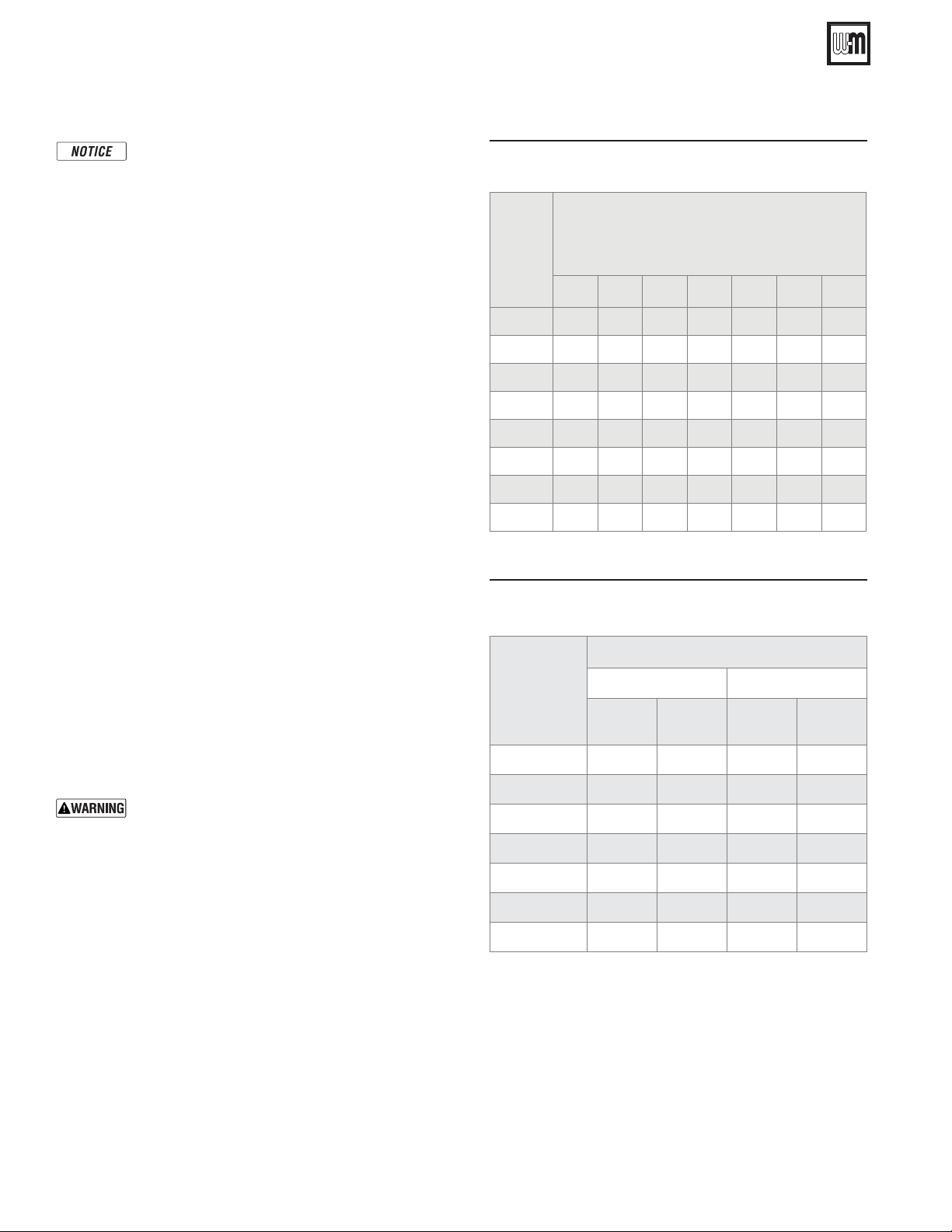
Figure 18 Pipe capacity for 0.60 specific gravity natural
gas; pipe length is in equivalent feet
Gas
pipe
total
length,
feet
10
20
30
40
50
75
100
150
Capacity
Cubic feet per hour, natural gas, 0.60 specific gravity
Gas pressure 13” w.c. or less
Pressure drop 0.3 inches w.c.
½” ¾” 1” 1¼” 1½” 2” 2½”
132 278 520 1050 1600 3050 4800
92 190 350 730 1100 2100 3300
73 152 285 590 890 1650 2700
NA 130 245 500 760 1450 2300
NA 115 215 440 670 1270 2000
NA 105 175 360 545 1020 1650
NA 96 150 305 460 870 1400
NA 90 120 250 380 710 1130
Figure 19 Equivalent lengths of straight pipe for typical
gas line fittings
Equivalent length, feet
Pipe size
(inches)
90° Elbow Tee
short
radius
long
radius
line
ÀRZ
branch
ÀRZ
Propane Gas:
You must follow the instructions, beginning on
page 10, to operate the boiler on propane. Failure
to comply could result in severe personal injury,
death or substantial property damage.
Pipe sizing for propane gas
1. Contact gas supplier to size pipes, tanks and 100% lockup
gas pressure regulator.
Propane supply pressure
1. Adjust propane supply regulator provided by gas supplier for
13” w.c. maximum pressure.
2. Pressure required at gas valve inlet pressure port:
a. Maximum: 13” w.c. with no flow (lockup).
b. Minimum: 3.5” w.c. gas pressure, with gas flowing
(verify during boiler startup, while boiler is at high fire).
Nominal gas pressure: 11.0” w.c.
14
½ 3.62.21.74.2
¾ 4.42.32.45.3
1 5.22.73.26.6
1¼ 6.63.24.68.7
1½ 7.43.45.69.9
2 8.5 3.6 7.7 12.0
2½ 9.3 4.0 9.3 13.0
Part number 550-100-325/0718
Page 15
AquaBalance® SERIES 2 WALL MOUNT GAS-FIRED WATER BOILER — Boiler Manual
6 Venting/air piping — general
mon venting system. Turn on any exhaust fans, such as
Any improper operation of the common venting system should
be corrected so the installation conforms with the National Fuel
Gas Code, ANSI Z223.1/NFPA 54, and/or the Natural Gas and
Propane Installation Code, CAN/CSA B149.1. When resizing
any portion of the common venting system, the common venting system should be resized to approach the minimum size as
determined using the appropriate tables in Chapter 13 of the
National Fuel Gas Code, ANSI Z223.1/NFPA 54, and/or the
Natural Gas and Propane Installation Code, CAN/CSA B149.1.
Do not install the boiler into a common vent
with any other appliance. This will cause flue
gas spillage or appliance malfunction, resulting
in possible severe personal injury, death or substantial property damage.
Existing common vent systems may be too large
for the appliances remaining connected after the
existing boiler is removed.
range hoods and bathroom exhausts, so they will operate
at maximum speed. Do not operate a summer exhaust fan.
Close fireplace dampers.
4. Place in operation the appliance being inspected. Follow
the operating instructions. Adjust thermostat so appliance
will operate continuously.
5. Test for spillage at draft hood relief opening after 5 minutes
of main burner operation. Use the flame of a match or
candle, or smoke from a cigarette, cigar, or pipe.
6. After it has been determined that each appliance remaining
connected to the common venting system properly vents
when tested as outlined herein, return doors, windows,
exhaust fans, fireplace dampers, and any other gas-burning
appliance to their previous conditions of use.
Failure to follow all instructions can result in
flue gas spillage and carbon monoxide emissions,
causing severe personal injury or death.
When removing a boiler from an
existing common vent system
The boiler cannot be common vented with any other appliance
. When an existing boiler is replaced with a boiler, the boiler
CANNOT use the existing common vent. The boiler requires its
own vent and air piping, as specified in this manual. This may cause
a problem for the appliances that remain on the old common vent,
because the vent may be too large. The following test is intended
to check for proper operation of the appliances remaining on the
old common vent system.
Vent system verification
Perform the test sequence below for each appliance remaining on
the original common vent system. Operate each appliance individually, with other appliances turned off. This procedure will test
whether the common vent system can properly vent each appliance.
Existing vent test procedure
(The following is intended to test whether the appliances
remaining on an existing vent system will operate
satisfactorily.)
1. Seal any unused openings in the common venting system.
2. Visually inspect the venting system for proper size and hori-
zontal pitch and determine there is no blockage or restriction,
leakage, corrosion or other deficiencies which could cause an
unsafe condition.
3. Test vent system — Insofar as is practical, close all building
doors and windows and all doors between the space in which
the appliances remaining connected to the common venting
system are located and other spaces of the building. Turn on
clothes dryers and any appliance not connected to the com-
Part number 550-100-325/0718
15
Page 16
AquaBalance® SERIES 2 WALL MOUNT GAS-FIRED WATER BOILER — Boiler Manual
6 Venting/air piping — general continued
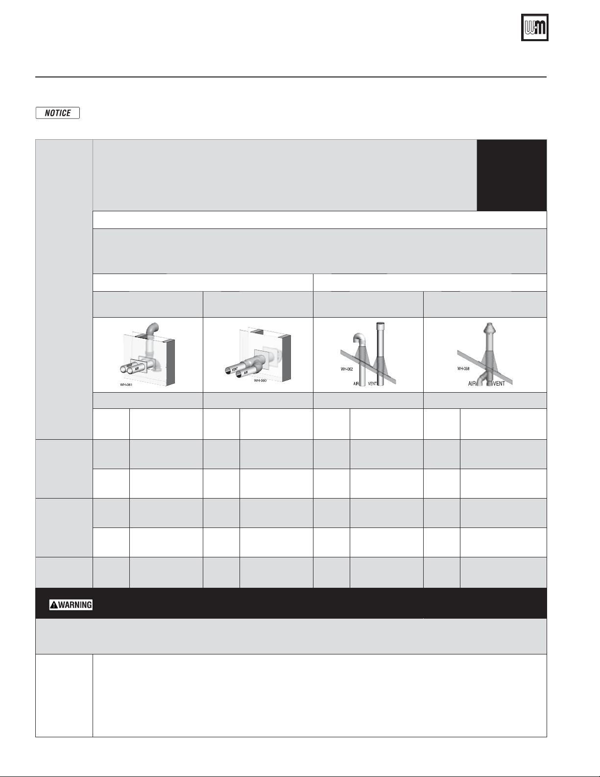
Figure 20 Venting and air piping — DIRECT VENT ONLY — OPTIONS and PIPING LIMITS
The table below lists the acceptable vent/air pipe terminations described in this manual. Follow all instructions provided to install the
vent/air system. NOT SHOWN below, but also approved, are the polypropylene piping and terminations listed in
For these applications, use ONLY the manufacturers’ parts listed and follow all instructions provided by the pipe manufacturer.
Figure 21, page 17
.
Maximum vent and air pipe length =
100 feet for all applications
(Minimum length for all applications is 2 feet equivalent plus termination)
(All applications include allowance for the termination fittings plus one elbow in air piping and one elbow in vent piping)
See Figure 21, page 17 for material specifications | See Figure 160, page 117 for part/kit numbers
Vent and air pipe sizes:
Maximum vent lengths apply for 3” vent and air pipe.
Boilers will derate as vent/air pipe length increases —
SIDEWALL termination VERTICAL termination
Separate pipes
[Note 1]
PVC or PP Concentric
[Note 1]
see rating data on Figure 174, page 131 for derate amounts.
*
Separate pipes
[Note 1]
AquaBalance® Model
See page 21 See page 23 See page 25 See page 27
Size,
inches
Materials
Fig. 21, page 19
Size,
inches
Materials
Fig. 21, page 19
Size,
inches
Materials
Fig. 21, page 19
PVC or PP Concentric
[Note 1]
Size,
inches
Fig. 21, page 19
USE
SWEEP
ELBOWS
ONLY
Materials
2
PVC/PVC-DWV
CPVC, PP, SS
2
PVC/PVC-DWV
80
3
2
PVC/PVC-DWV
CPVC, PP, SS
PVC/PVC-DWV
CPVC, PP, SS
3
2
PVC/PVC-DWV
PVC/PVC-DWV
120
3
155 3
All elbows in vent and air piping must be sweep elbows ONLY. DO NOT use short-radius elbows.
Equivalent feet for elbows (USE SWEEP ELBOWS ONLY) —
• 7 feet per for each additional 90° sweep elbow or 45° elbow —
ABS may be used for intake air.
Material abbreviations: PP = polypropylene, SS = AL29-4C stainless steel.
Note 1:
If using stainless pipe, provide adapters for terminations, if required.
IPEX 3” PVC concentric vent kits can be used with standard PVC pipe, fittings and cement (ANSI/ASTM D1785) except if ULC S636
compliance is required. For ULC S636 compliance, all pipe, fittings and cement must be IPEX System 636. If using IPEX kits, use only
IPEX product code 196006 for 3” venting.
Contact Weil-McLain for ordering information and availability of Weil-McLain venting kits.
PVC/PVC-DWV
CPVC, PP, SS
PVC/PVC-DWV
CPVC, PP, SS
3
3
PVC/PVC-DWV
PVC/PVC-DWV
CPVC, PP, SS
CPVC, PP, SS
CPVC, PP, SS
CPVC, PP, SS
CPVC, PP, SS
deduct from max equivalent length of piping (does not apply to termination fittings).
If piping contains more than 1 elbow in air or vent piping, other than termination fittings.
2
3
2
3
3
PVC/PVC-DWV
CPVC, PP, SS
PVC/PVC-DWV
CPVC, PP, SS
PVC/PVC-DWV
CPVC, PP, SS
PVC/PVC-DWV
CPVC, PP, SS
PVC/PVC-DWV
CPVC, PP, SS
2
3
2
3
3
PVC/PVC-DWV
CPVC, PP, SS
PVC/PVC-DWV
CPVC, PP, SS
PVC/PVC-DWV
CPVC, PP, SS
PVC/PVC-DWV
CPVC, PP, SS
PVC/PVC-DWV CPVC,
PP, SS
16
Part number 550-100-325/0718
Page 17

AquaBalance® SERIES 2 WALL MOUNT GAS-FIRED WATER BOILER — Boiler Manual
6 Venting/air piping — general continued
Figure 21 Vent and air piping materials — Use only the materials listed below, ensuring that all materials meet local
codes (see Figure 160, page 117 for part/kit numbers).
Item Material
Plastic piping materials Vent or air piping Vent piping Air piping
Vent or air pipe
&
¿WWLQJV
PVC & ABS pipe
cement & primer
Polypropylene
YHQWSLSH¿WWLQJV
terminations and
cement
Vent pipe
PVC-DWV schedule 40 (Note 1) ANSI/ASTM D2665 NA
CPVC schedule 40
Simpson-Duravent — Obtain all materials from
M&G Simpson-Duravent
Centrotherm Eco Systems InnoFlue® Singlewall — Obtain all materials from Centrotherm
Heat Fab, Inc. — Saf-T-Vent
AL29-4C
stainless
steel
Metal-Fab, Inc. — CORR/GUARD
Standards for installations in:
United States Canada (Note 2)
PVC schedule 40 ANSI/ASTM D1785 ULC S636
(Note 1) ANSI/ASTM F441 ULC S636
PVC ANSI/ASTM D2564/F656 ULC S636
CPVC (Note 1) ANSI/ASTM F493 ULC S636
See manufacturer’s literature
for detailed information
MUST USE LOCKING
COLLAR ON EVERY JOINT
AL29-4C stainless steel piping materials
®
Z-Flex, Inc. — Z-Vent II
Dura-Vent — FasNSeal®
Certified for direct vent
appliance venting
Certified for direct vent appliance
venting
ULC S636
PVC, PVC-DWV,
CPVC or
polypropylene
Use only cement
and primer suitable
for piping material
used
PVC, PVC-DWV,
CPVC or
polypropylene
Stainless steel bird screens, 2” or 3” (purchase separately) — see Figure 160, page 117 for part numbers
Note 1: Weil-McLain concentric vent kits are made from PVC
Note 2: System 636 PVC concentric terminations utilize PVC
pipe and fittings.
pipe/fittings certified to ULC S636.
If ULC S636 compliance is required, use only System
636 pipe, fittings and cement.
DO NOT mix piping from different pipe manufactur-
ers unless using adapters specifically designed for
the purpose by the manufacturer.
Every joint on polypropylene vent piping must
include a locking collar.
DO NOT use cellular core PVC (ASTM F891), cellular
core CPVC, or Radel® (polyphenolsulfone) in venting
systems.
DO NOT cover non-metallic vent pipe and fittings
with thermal insulation.
USE SWEEP ELBOWS FOR ALL VENT AND AIR PIPING — DO NOT use short
radius elbows for vent or air piping. Boiler performance could be affected.
ALL vent and air pipes require a BIRD SCREEN at each termination. Most kits do not include
the bird screens. Purchase bird screens separately from Weil-McLain or vent kit supplier if
not included. [Note — bird screening is integral to the 3" PVC Weil-McLain sidewall vent
cap,
available for purchase from Weil-McLain
ADAPTERS – The boiler comes with a 3”,
3-in-1 adapter as standard. This adapter allows the
installation of 3” PVC schedule 40, CPVC schedule 40,
PVC-DWV schedule 40, AL29-4C stainless steel and
Polypropylene (from Simpson-Duravent only) piping
without the need for extra adapters.
It may require an adapter at terminations.
If your venting system uses Centrotherm Eco
systems InnoFlue single wall material, then an approved adapter is required.
If using 2” piping (AB-80/120 only), where ap-
proved for the application, provide adapters for a
3” pipe material (mentioned above) connections
and at the terminations, if required.
. No additional screening is required.]
Part number 550-100-325/0718
17
Page 18

AquaBalance® SERIES 2 WALL MOUNT GAS-FIRED WATER BOILER — Boiler Manual
7 Commonwealth of Massachusetts installations
Commonwealth of Massachusetts — When the boiler is installed within the Commonwealth of Massachusetts,
the boiler must be installed by a licensed plumber or gas fitter. Read and comply with the instructions below.
(a) For all sidewall horizontally-vented gas-fueled equipment
installed in every dwelling, building or structure used in
whole or in part for residential purposes, including those
owned or operated by the Commonwealth and where the
side wall exhaust vent termination is less than seven (7) feet
above finished grade in the area of the venting, including but
not limited to decks and porches, the following requirements
shall be satisfied:
INSTALLATION OF CARBON MONOXIDE DETEC-
1.
TORS
. At the time of installation of the side wall horizontal vented gas fueled equipment, the installing plumber or
gas fitter shall observe that a hard wired carbon monoxide
detector with an alarm and battery back-up is installed on
the floor level where the gas equipment is to be installed.
In addition, the installing plumber or gas fitter shall
observe that a battery operated or hard wired carbon
monoxide detector with an alarm is installed on each additional level of the dwelling, building or structure served
by the side wall horizontal vented gas fueled equipment.
It shall be the responsibility of the property owner to
secure the services of qualified licensed professionals for
the installation of hard wired carbon monoxide detectors
a. In the event that the side wall horizontally vented gas
fueled equipment is installed in a crawl space or an
attic, the hard wired carbon monoxide detector with
alarm and battery back-up may be installed on the
next adjacent floor level.
b. In the event that the requirements of this subdivision
can not be met at the time of completion of installation, the owner shall have a period of thirty (30) days
to comply with the above requirements; provided,
however, that during said thirty (30) day period, a
battery operated carbon monoxide detector with an
alarm shall be installed.
APPROVED CARBON MONOXIDE DETECTORS. Each
2.
carbon monoxide detector as required in accordance with
the above provisions shall comply with NFPA 720 and be
ANSI/UL 2034 listed and IAS certified.
SIGNAGE. A metal or plastic identification plate shall
3.
be permanently mounted to the exterior of the building at a minimum height of eight (8) feet above grade
directly in line with the exhaust vent terminal for the
horizontally vented gas fueled heating appliance or
equipment. The sign shall read, in print size no less than
one-half (1/2) inch in size, “GAS VENT DIRECTLY BELOW. KEEP CLEAR OF ALL OBSTRUCTIONS.”
INSPECTION. The state or local gas inspector of the
4.
side wall horizontally vented gas fueled equipment shall
not approve the installation unless, upon inspection,
the inspector observes carbon monoxide detectors and
signage installed in accordance with the provisions of
248 CMR 5.08(2)(a) 1 through 4.
(b)
EXEMPTIONS: The following equipment is exempt from
248 CMR 5.08(2)(a)1 through 4:
1. The equipment listed in Chapter 10 entitled “Equipment
Not Required To Be Vented” in the most current edition
of NFPA 54 as adopted by the Board; and
2. Product Approved side wall horizontally vented gas fueled
equipment installed in a room or structure separate from
the dwelling, building or structure used in whole or in
part for residential purposes.
(c)
MANUFACTURER REQUIREMENTS — GAS EQUIPMENT
VENTING SYSTEM PROVIDED
Product Approved side wall horizontally vented gas equipment provides a venting system design or venting system
components with the equipment, the instructions provided
by the manufacturer for installation of the equipment and
the venting system shall include:
1. Detailed instructions for the installation of the venting
system design or the venting system components; and
2. A complete parts list for the venting system design or
venting system.
(d)
MANUFACTURER REQUIREMENTS — GAS EQUIPMENT
VENTING SYSTEM NOT PROVIDED
turer of a Product Approved side wall horizontally vented gas
fueled equipment does not provide the parts for venting the
flue gases, but identifies “special venting systems”, the following requirements shall be satisfied by the manufacturer:
1. The referenced “special venting system” instructions shall
be included with the appliance or equipment installation
instructions; and
2. The “special venting systems” shall be Product Approved
by the Board, and the instructions for that system shall
include a parts list and detailed installation instructions.
(e) A copy of all installation instructions for all Product Approved
side wall horizontally vented gas fueled equipment, all venting
instructions, all parts lists for venting instructions, and/or all
venting design instructions shall remain with the appliance
or equipment at the completion of the installation.
. When the manufacturer of
. When the manufac-
18
Part number 550-100-325/0718
Page 19
AquaBalance® SERIES 2 WALL MOUNT GAS-FIRED WATER BOILER — Boiler Manual
8 Vent termination requirements
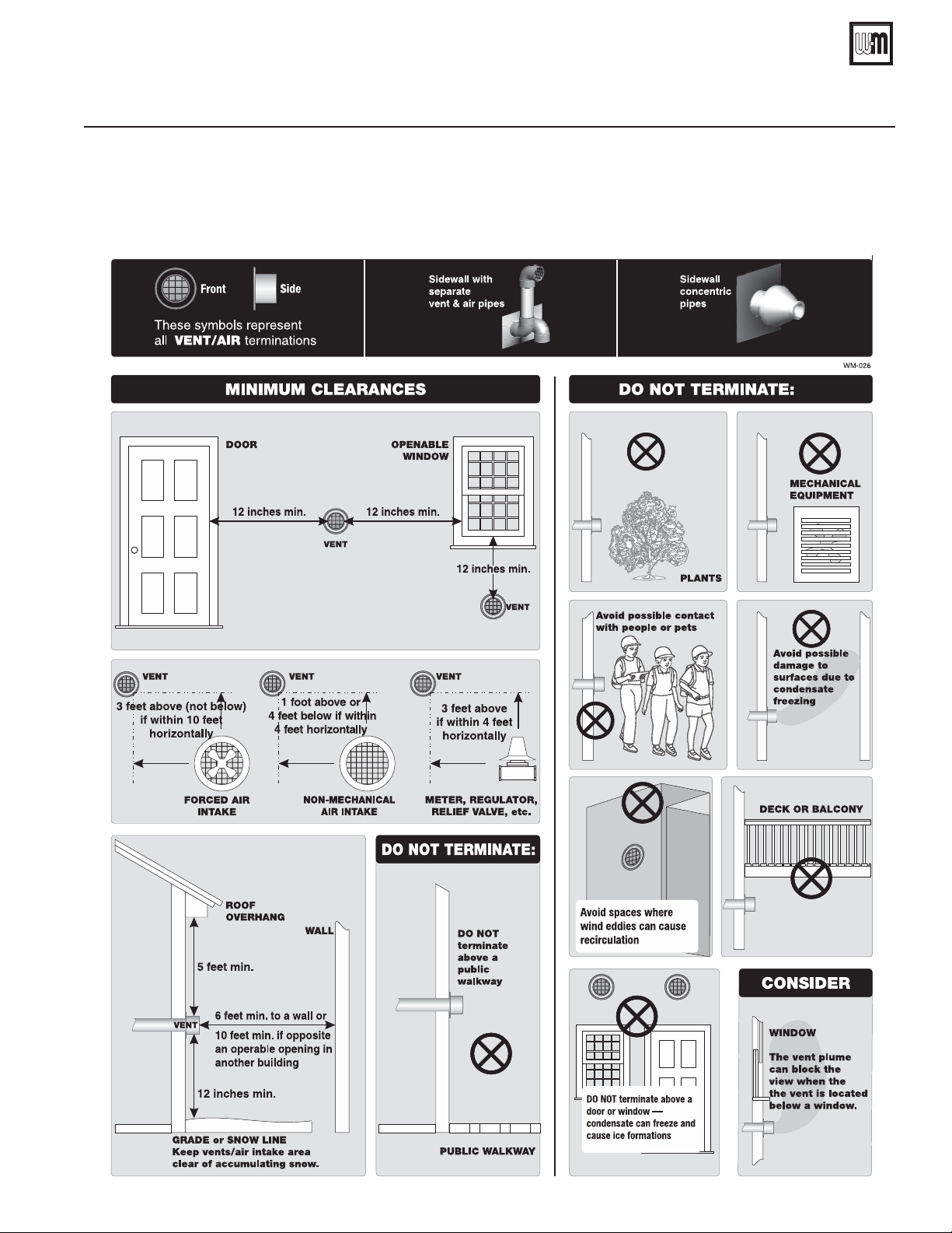
Figure 22
The vent termination must be located to meet all requirements below (also applies to vertical vent terminations). The minimum distance
from adjacent public walkways, adjacent buildings, openable windows and building in the National Fuel Gas Code, ANSI Z223.1/NFPA
54 - latest edition and/or the Natural Gas and Propane Installation Code, CAN/CSA B149.1. The vent termination clearances below are
for U.S.A., for Canadian vent termination clearances please refer to the requirements of CAN/CSA B149.1 Natural Gas and Propane
Installation Code. Consideration should be given to avoid possible damage caused by vent plumes and condensate when choosing a
YHQWLQJFRQ¿JXUDWLRQDQGORFDWLRQ0DLQWDLQDPLQLPXPFOHDUDQFHRIIWPKRUL]RQWDOO\IURPDQGLQQRFDVHDERYHRUEHORZXQOHVV
DIWPKRUL]RQWDOGLVWDQFHLVPDLQWDLQHGIURPHOHFWULFDOPHWHUVJDVPHWHUVUHJXODWRUVDQGUHOLHIHTXLSPHQW
Part number 550-100-325/0718
19
Page 20
AquaBalance® SERIES 2 WALL MOUNT GAS-FIRED WATER BOILER — Boiler Manual
9 Boiler room air openings
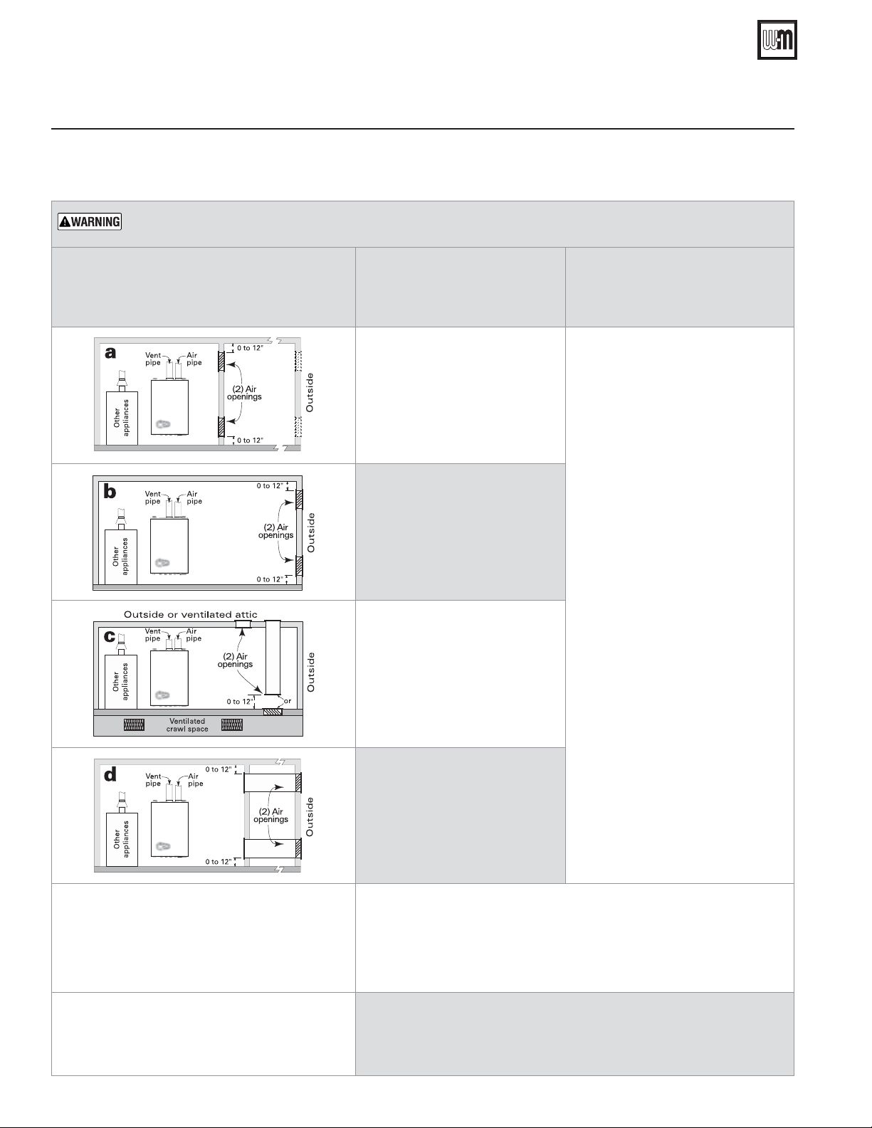
Figure 23 Combustion and ventilation air openings for Direct Vent installations, also follow the National Fuel Gas Code,
ANSI Z223.1/NFPA 54 - latest edition, and/or Natural Gas and Propane Installation Code, CAN/CSA B149.1 or
applicable provisions of the local building codes.
The boiler CANNOT be in the same space with other appliances if clearances around the are less than the recom-
mended service clearances shown in Figure 1, page 5.
Air openings
The required air opening sizes below are FREE AREA,
after reduction for louver obstruction. Note the exception below for large spaces.
Boiler
WITH other
appliances in room
TWO openings, each at least:
1 square inch per 1,000 Btuh
of all other appliances in the room
(Unless specified otherwise by
appliance manufacturer)
TWO openings, each at least:
1 square inch per 4,000 Btuh
of all other appliances in the room
— OR —
ONE opening **, each at least:
1 square inch per 3,000 Btuh
of all other appliances in the room
(Unless specified otherwise by
appliance manufacturer)
TWO openings, each at least:
1 square inch per 4,000 Btuh
of all other appliances in the room
— OR —
ONE opening **, each at least:
1 square inch per 3,000 Btuh
of all other appliances in the room
(Unless specified otherwise by
appliance manufacturer)
Boiler
WITHOUT other
appliances in room
NO openings are required if the
boiler installation provides at least the
recommended service clearances
shown in Figure 1, page 5.
Provide openings ONLY as shown
in Figure 1, page 5.
Each opening must have a free
area no less than 1 square inch per
1,000 Btuh input of the boiler.
** NOTICE:
Requirements for using the SINGLE air opening
option.
SPECIAL EXCEPTION FOR LARGE SPACES
(Boiler WITH other appliances in room only):
20
TWO openings, each at least:
1 square inch per 2,000 Btuh
of all other appliances in the room
ONE opening **, each at least:
1 square inch per 3,000 Btuh
of all other appliances in the room
(Unless specified otherwise by
appliance manufacturer)
A single combustion air opening can be used for cases b, c or d above (boiler with
other appliances in room only), sized as listed, provided that:
• The single opening must communicate directly to the outdoors or to a space that
communicates directly with outdoors (NOT to an interior space).
• The top of the opening must be within 12 inches of the ceiling.
• The free area of the opening must be at least equal to the sum of the areas of all
equipment vent connectors in the space.
NO combustion air openings are needed if the boiler (and other appliances) are
installed in a space with a volume NO LESS than 50 cubic feet per 1,000 Btuh of all
appliances in the space. That is, total the input of all appliances in MBH (1,000’s of
Btuh), then multiply this total times 50. The building MUST NOT be of tight construction.
Example: For a total input of 500 MBH (500,000 Btuh), the minimum volume would
be 50 x 500 = 25,000 cubic feet.
— OR —
Part number 550-100-325/0718
Page 21
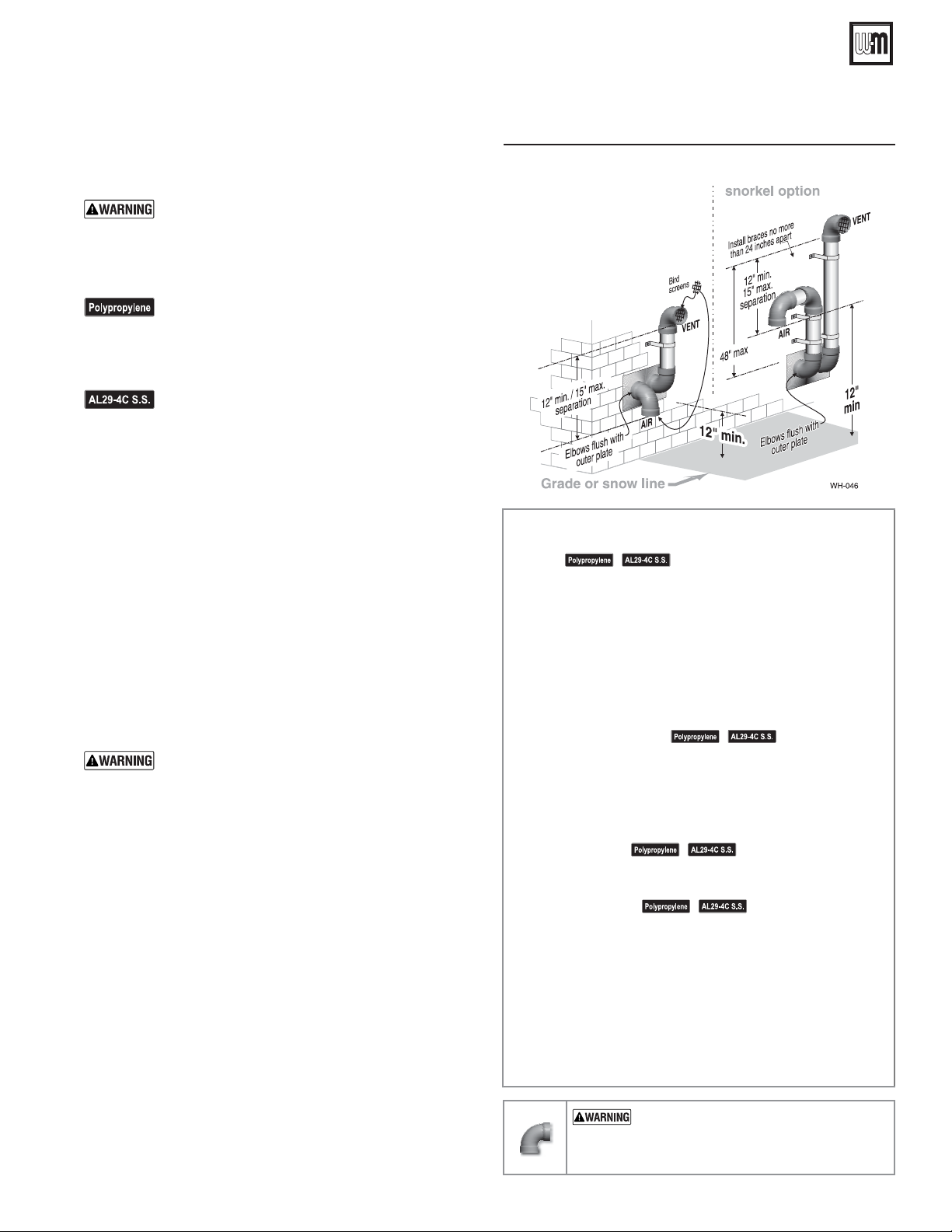
AquaBalance® SERIES 2 WALL MOUNT GAS-FIRED WATER BOILER — Boiler Manual
10 DIRECT VENT — Sidewall with separate pipes
Allowable vent/air pipe materials &
lengths
Use only the vent materials and kits listed in
Figure 21, page 17. Provide pipe adapters if specified.
1. Locate the termination such that the total air piping and vent
piping from the boiler to the termination will not exceed the
maximum length given in Figure 20, page 16.
For polypropylene applications, comply with any
additional requirements in the vent system manufacturer’s instructions. (Do Not use 3” PVC transition
pieces at the boiler vent and air connections). Install
a locking collar at every joint.
For AL29-4C vent pipe applications, comply with
any additional requirements in the vent system
manufacturer’s instructions. Provide a AL29-4C
starter piece from the AL29-4C manufacturer for the
transition piece at the boiler vent connection. The
air piping must be PVC or CPVC. Provide a 3” PVC
transition piece at the boiler air connection if using
2” air piping.
Determine termination location
1. Wall penetration thickness between 2” to 24”.
2. The air and vent terminations must be installed as shown in
Figure 24, page 21 and Figure 26, page 22.
3. The terminations must comply with clearances and limitations
shown in Figure 22, page 19.
4. Locate the terminations so they are not likely to be damaged
by foreign objects, such as stones or balls, or subject to buildup
of leaves or sediment.
5. Vent and air locations can be on different building walls.
Example: Vent/exhaust can be on North building wall and air
intake can be on South building wall. (Different pressure zone).
Do not exceed the maximum lengths of the outside
vent piping shown in Figure 24. Excessive length
exposed to the outside could cause freezing of
condensate in the vent pipe, resulting in potential
boiler shutdown. In extremely cold climates, install
an insulated chase around the vent piping, particularly if using longer lengths. The chase must allow
for inspection of the vent pipe, and insulation must
be protected from water.
Multiple vent/air terminations
1. When terminating multiple boilers, terminate each vent/air
connection as described in this manual.
2. Place wall penetrations to obtain minimum clearances shown
in Figure 24 for U. S. installations. For Canadian installations,
provide clearances required by CSA B149.1 or B149.2 Installation Code and a ULC S636 compliant vent kit.
3. The air inlet of a boiler is part of a direct vent connection. It
is not classified as a forced air intake with regard to spacing
from adjacent boiler vents.
Prepare wall penetrations
1. Air pipe penetration:
a. Cut a hole for the air pipe. Size the air pipe hole as close as
desired to the air pipe outside diameter.
2. Vent pipe penetration:
Part number 550-100-325/0718
Figure 24 INSTALLATION SEQUENCE — Separate pipes
sidewall
Step 1 Read and follow all instructions in this manual.
Step 2 Install the boiler in a location that allows proper routing
Step 3 Make sure the selected sidewall termination location com-
Step 4 Use only the vent materials listed in Figure 21, page 17.
Step 5 Prepare the sidewall penetrations and secure the sidewall
Step 6 The air piping must terminate in a down-turned elbow as
Step 7 Install vent and air piping between the boiler and the side-
Step 8 Install pipe supports every 5 feet on both the horizontal
Step 9 Attach the vent termination exterior piping: Use either of the
Step 10 The vent and air pipes may run up as high as 4 feet with
Step 11 External venting greater than 4 feet requires an insulated
DO NOT proceed with vent/air installation
until you have read page 17 through page 20.
of all vent and air piping to the selected sidewall location.
plies with Figure 22, page 19. (Multiple boiler sidewall plates
must also comply with Figure 25, page 22.)
Provide pipe adapters where required. Vent piping and
air piping lengths must not exceed the values shown in
Figure 20, page 16.
plates as instructed in this section. See “Prepare wall penetrations” on page 21.
shown above. The vent piping must terminate in an elbow
pointed outward or away from the air inlet as shown
above. See illustration above.
wall openings. Slope horizontal piping downward toward
the boiler at least 1/4 inch per foot. See page 30 for general
guidelines.
and vertical runs. Install a hanger support within 6 inches
of any upturn in the piping, or per vent pipe manufacturer’s
instructions.
configurations shown above, as needed to ensure clearance
above grade or snow line. Keep vents/air intake area clear
of accumulating snow.
no enclosure. The vent and air pipes must be secured with
braces, and all clearances and lengths must be maintained.
Space braces no further than 24 inches apart.
enclosure around the vent and air pipes. The vent and air
terminations must exit through the enclosure as shown in
the illustration above, maintaining all required clearances.
See notices at left.
See notices at left.
See notices at left.
See notices at left.
USE SWEEP ELBOWS FOR ALL VENT
AND AIR PIPING — DO NOT use short radius
elbows for vent or air piping. Boiler performance
could be affected.
21
Page 22
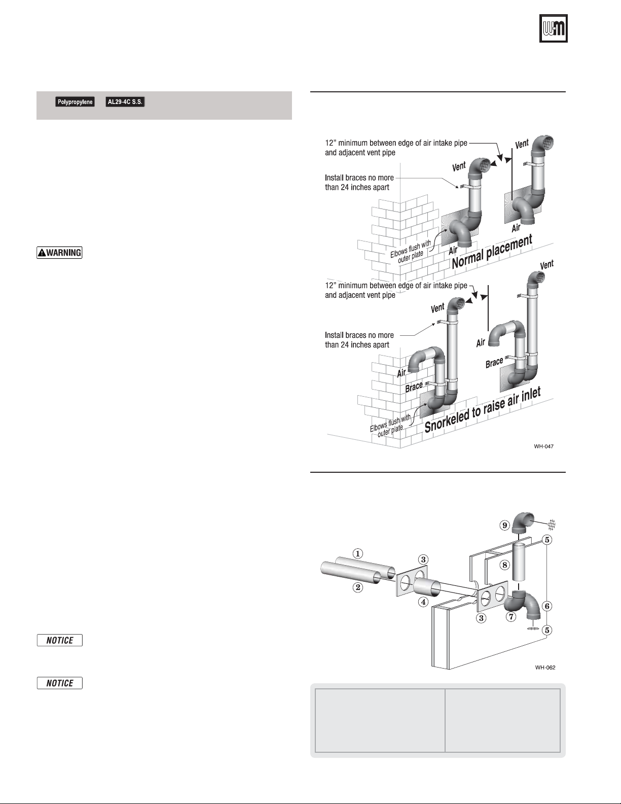
AquaBalance® SERIES 2 WALL MOUNT GAS-FIRED WATER BOILER — Boiler Manual
10 DIRECT VENT — Sidewall with separate pipes continued
See notices on previous page.
a. Cut a hole for the vent pipe. For either combustible or
noncombustible construction, size the vent pipe hole at
least 0.4” larger than the vent pipe diameter.
b. Insert a galvanized metal thimble in the vent pipe hole
as shown in Figure 26.
c. Plate may be field fabricated from corrosion resistant
material of sufficient strength. Plate must allow venting
to maintain minimum clearance to combustibles.
Ensure that the plate material is strong enough to
prevent the termination from being pushed inward
if struck or pushed from the outside.
1. Follow all local codes for isolation of vent pipe when passing
through floors or walls.
2. Seal exterior openings thoroughly with exterior caulk.
Termination and fittings
1. Prepare the vent termination elbow and the air termination elbow by inserting bird screens.
(See Figure 24, page 21.) Bird screens must be purchased
separately. See the parts list at the end of this manual for
part numbers.
2. Secure the elbows so they will butt against the sidewall termination plate.
3. When completed, the air termination coupling must be
oriented at least 12 inches below the vent termination and
at least 12 inches above grade or snow line as shown in Figure 24, page 21.
snow.
4. You can orient the vent termination elbow either directly
outward or 90 degrees away from the air inlet elbow as shown
in Figure 24, page 21.
5. Maintain the required dimensions of the finished termination
piping as shown in Figure 24, page 21.
6. For multiple boiler terminations, see Figure 25.
7. Do not extend exposed vent pipe outside of building more
than shown in this document. Condensate could freeze and
block vent pipe.
Keep vents/air intake area clear of accumulating
Figure 25
Multiple separate pipes sidewall terminations —
maintain vertical spacing between vent and air
fittings shown in Figure 24, page 21.
Figure 26 Sidewall termination assembly — using
separate pipes
22
If extending the vent and air pipes out from the wall,
install a coupling on each pipe. Mount the piping
with the coupling flush with the outer plate.
Wall penetration thickness between 2” to 24”.
1 Vent piping
2 Air piping
3 Sidewall termination plates: for 3” PVC
or 3” AL29-4C or 2” PVC, (field supplied)
4 Galvanized thimbles, by installer
5 Bird screen, by installer
6 Air inlet elbow
7 Elbow
8 Nipple
9 Vent termination elbow
Part number 550-100-325/0718
Page 23
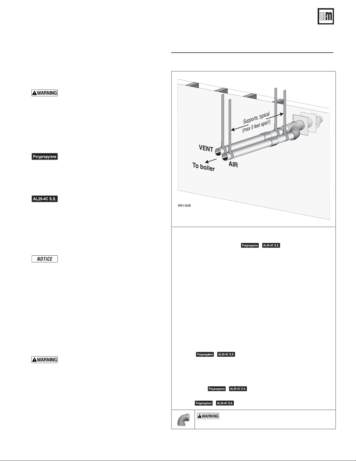
AquaBalance® SERIES 2 WALL MOUNT GAS-FIRED WATER BOILER — Boiler Manual
11 DIRECT VENT — Sidewall concentric
Allowable vent/air pipe materials
& lengths
1. The concentric termination kit must be purchased
separately.
Use only the vent materials and kits listed in
Figure 21, page 17
specified.
2. Locate the termination such that the total air pip
ing and vent piping from the boiler to the termination will not exceed the maximum length given in
Figure 20, page 16
.
3. This termination requires a 45-degree elbow that is
not supplied with the termination kit. The maximum
vent/air pipe lengths include allowance for this elbow.
For polypropylene applications, comply
with any additional requirements in the
vent system manufacturer’s instructions.
(Do Not use 3” PVC transition pieces at the
boiler vent and air connections)
termination if using a 3” PVC concentric
vent kit. Install a locking collar at every joint.
For AL29-4C vent pipe applications, comply
with any additional requirements in the vent
system manufacturer’s instructions.
a AL29-4C starter piece from the AL29-4C
manufacturer to the
vent connection. Air pipe must be PVC or
CPVC. Provide a 3” PVC transition at the
boiler air connection if using 2” air pipe.
Provide transition pieces to PVC at the vent
and air pipe termination connections.
Wall penetration thickness between 2” to
24”.
Determine termination location
1. The concentric termination kit must be installed as
shown in Figure 29, page 24.
2. The termination must comply with clearances and
limitations shown in
3. Locate the termination so it is not likely to be damaged
by foreign objects, such as stones or balls, or subject
to buildup of leaves or sediment.
Multiple vent/air terminations
1. When terminating multiple boilers, install each concentric termination as described in this manual.
All vent pipes and air inlets must terminate
at the same height to avoid possibility of
severe personal injury, death or substantial
property damage.
2. Place wall penetrations to obtain minimum clear
ance as shown in Figure 28, page 24 for U. S. installa-
For Canadian installations, provide clearances
tions.
required by CSA B149.1 or B149.2 Installation Code
and a ULC S636 compliant vent kit.
3. The air inlet of a boiler is part of a direct vent connection. It is not classified as a forced air intake with
regard to spacing from adjacent boiler vents.
. Provide pipe adapters if
transition at the boiler
Figure 22, page 19
.
and at the
Provide
Figure 27 INSTALLATION SEQUENCE — Concentric horizontal
-
Step 1 Read and follow all instructions in this manual. DO NOT proceed
Step 2 Install the boiler in a location that allows proper routing of all vent
Step 3 Make sure the selected sidewall termination location complies with
Step 4 Use only the vent materials listed in Figure 21, page 17. Provide pipe
Step 5 Vent piping and air piping lengths must not exceed the values shown
Step 6 The concentric termination must be assembled and installed before
Step 7 Prepare the sidewall penetration — assemble the concentric ter-
Step 8 Install vent and air piping between the boiler and the concentric
Step 9 Install pipe supports every 5 feet on both the horizontal and vertical
-
Step 10 Install a hanger support within 6 inches of any upturn in the piping.
with vent/air installation until you have read page 15
through page 20.
and air piping to the selected sidewall location.
Figure 22, page 19. (Multiple boiler concentric terminations must
also comply with
adapters where required.
in Figure 20, page 16.
piping from the boiler to the termination.
mination kit and secure the cover plates as instructed in this section. Provide the supports indicated and mount the termination
assembly. See “Install termination — concentric pipes” on page 24.
vent/air termination. Slope horizontal piping downward toward the
boiler at least 1/4 inch per foot. See page 30 for general guidelines.
runs.
See notices at left.
Figure 28, page 24
See notices at left.
See notices at left.
USE SWEEP ELBOWS FOR ALL VENT AND AIR
PIPING — DO NOT use short radius elbows for vent or
air piping. Boiler performance could be affected.
See notices at left.
.)
Part number 550-100-325/0718
23
Page 24
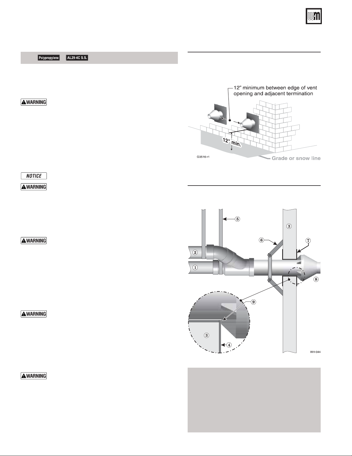
AquaBalance® SERIES 2 WALL MOUNT GAS-FIRED WATER BOILER — Boiler Manual
11 DIRECT VENT — Sidewall concentric (continued)
See notices on previous page.
Install termination — concentric pipes
1. Assemble the vent termination as described for concentric terminations, on page 29.
If necessary, you can shorten the lengths of the inner and
outer pipes for a shorter finished assembly. But you must
ensure the pipes butt correctly at both ends. Failure to
properly assemble the concentric termination can result
in flue gas recirculation, causing possible severe personal
injury or death.
2. Wall penetration:
a. Preferably, use a thimble with a 4½-inch hole. If not using a
thimble, carefully use a hole saw to cut a hole not larger than
4¾ inches in diameter through the wall. The finished hole
must provide a solid stop for the rain cap ribs, as shown in the
inset to Figure 29.
Wall penetration thickness between 2” to 24”.
Ensure that the wall material is strong enough to pre-
vent the rain cap from being pushed inward if struck or
pushed from the outside.
3. Secure the termination in place so the rain cap will butt against the
outside wall or outer thimble plate as shown in Figure 29.
4. Before beginning vent and air piping from the boiler to the concentric termination, mount and secure the concentric termination
as shown in Figure 29.
The vent and air piping must be securely supported, and
must not rest its weight on the boiler fittings. Failure to
properly support the vent and air piping could result in
vent piping damage, resulting in possible severe personal
injury, death or substantial property damage.
Figure 28 Termination location — concentric
termination — multiple boilers —
clearance from vent of one to air intake of
the next
Figure 29 Installing and supporting the concentric
sidewall vent assembly
The supports/bracing used must support the termination
assembly to prevent slippage or movement. See instructions provided with concentric kit for details.
The clamps used on the outside of the termination pipe
must not cut into the pipe or contain sharp edges that
could cause a crack to form.
When inserting the partially-assembled termination kit
through the wall penetration, wrap plastic or other protection over the end of the exposed assembly to prevent
debris from entering the pipes. If the air passages become
blocked, the boiler will not operate. Once the rain cap
has been cemented to the assembly, there is no way to
correct the problem. The assembly would have to be replaced if it were cut to be removed and cleaned. Altering
the assembly in any way could result in severe personal
injury or death due to toxic flue product emissions.
If using AL29-4C stainless vent pipe, use the vent pipe
manufacturer’s PVC adapter if connecting to a PVC
concentric vent attachment.
5. After the assembly has been positioned in the opening and all supports have been attached, install a bird screen (purchased separately
if not included with the kit) and rain cap as follows:
a. Place the bird screen on the end of the inner pipe as in
Figure 35, page 29, or per concentric kit instructions for polypropylene kits.
b. Cement the rain cap in place as shown.
LEGEND for Figure 29
1 Vent pipe
2 Air pipe
3 Wall
4 Outer thimble plate
5 Supports every 5 feet or
per vent pipe mfg’s instructions
6 Wall brace, by installer,
(or see vent pipe mfg’s
instructions)
7 Thimble, by installer
8 Rain cap
9 Rain cap ribs must butt
against outer thimble
plate or wall opening
24
Part number 550-100-325/0718
Page 25
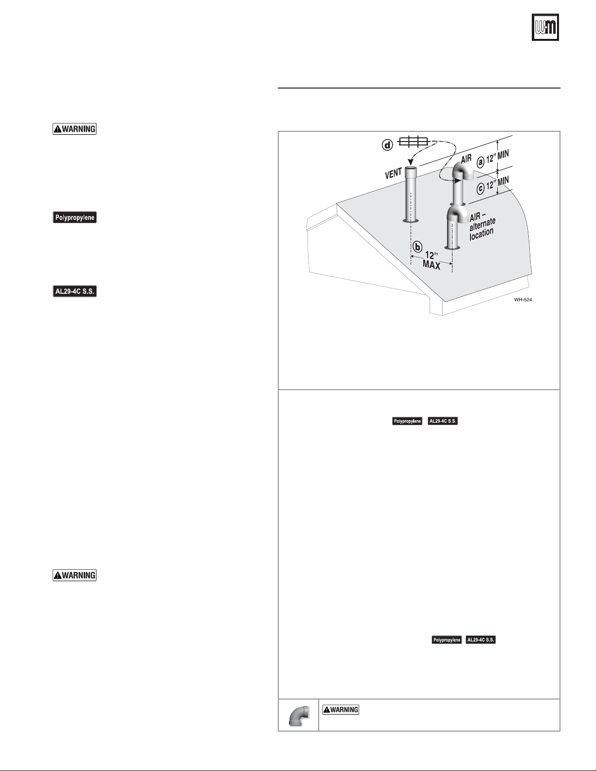
AquaBalance® SERIES 2 WALL MOUNT GAS-FIRED WATER BOILER — Boiler Manual
12 DIRECT VENT — Vertical with separate pipes
Allowable vent/air pipe materials
& lengths
Use only the vent materials and kits listed
in Figure 21, page 17. Provide pipe adapters if specified.
1. Locate the terminations such that the total air piping
and vent piping from the boiler to the termination
will not exceed the maximum length given in Figure 20, page 16.
For polypropylene applications, comply
with any additional requirements in the
vent system manufacturer’s instructions.
(Do Not use 3” PVC transition pieces
at the boiler vent and air connections).
Install a locking collar at every joint.
For AL29-4C vent pipe applications,
comply with any additional requirements
in the vent system manufacturer’s instructions. Provide a AL29-4C starter piece
from the AL29-4C manufacturer to the
transition piece at the boiler vent connection. The air piping must be PVC or
CPVC. Provide a 3” PVC transition piece
at the boiler air connection if using 2” air
piping.
Figure 30 Separate pipes vertical termination
Terminate vent and air pipes such that:
a. AIR INTAKE IS AT LEAST 12 inches below vent outlet
b. AIR INTAKE IS NO FURTHER than 12 inches away center to center
c. AIR INTAKE IS AT LEAST 12 inches above roof or snow line,
keep vents/air intake area clear of accumulating snow.
d. Vent and air terminations are fitted with bird screens
Determine termination location
1. The air and vent terminations must be installed as
shown in Figure 30.
2. The terminations must comply with clearances and
limitations shown in Figure 22, page 19.
3. Locate the terminations so they are not likely to be
damaged by foreign objects, such as stones or balls,
or subject to buildup of leaves or sediment.
Multiple vent/air terminations
1. When terminating multiple boilers, terminate each
vent/air connection as described in this manual.
Terminate all vent pipes at the same height
and all air pipes at the same height to
avoid possibility of severe personal injury,
death or substantial property damage.
2. Place roof penetrations to obtain minimum clearance of 12 inches between edge of air intake elbow
and adjacent vent pipe of another boiler for U. S.
installations (see Figure 33, page 28).
3. For Canadian installations, provide clearances required by CSA B149.1 or B149.2 Installation Code
and a ULC S636 compliant vent kit.
Step 1 Read and follow all instructions in this manual. DO NOT proceed
Step 2 Install the boiler in a location that allows proper routing of all vent
Step 3 Make sure the selected vertical termination location complies with
Step 4 Use only the vent materials listed in Figure 21, page 17. Provide pipe
Step 5 Prepare the vertical penetrations and secure penetration components as
Step 6 The air piping must terminate in a 180-degree return bend or down-
Step 7 Install vent and air piping between the boiler and the vertical termina-
Step 8 Insert the vent and air piping through the vertical penetrations and
Step 9 Maintain clearances shown above. Vent and air terminations must be
with vent/air installation until you have read page 17
through page 20.
and air piping to the selected sidewall location.
Figure 22, page 19. (Multiple boiler terminations must also comply
with Figure 31, page 26.)
adapters where required. Vent piping and air piping lengths must not
exceed the values shown in Figure 20, page 16.
instructed in this section. See “Prepare roof penetrations” on page 26
and “Termination and fittings” on page 26.
turned elbow as shown above. The vent piping must terminate in a
coupling pointed upward as shown above.
tions. Slope horizontal piping downward toward the boiler at least 1/4
inch per foot. Install pipe supports every 5 feet on both the horizontal
and vertical runs. Install a hanger support within 6 inches of any upturn
in the piping. See page 30 for general guidelines. Also comply with vent
pipe manufacturer’s instructions.
secure the termination fittings.
fitted with a bird screen as shown.
See notices at left.
See notices at left.
4. The air inlet of a boiler is part of a direct vent connection. It is not classified as a forced air intake with
regard to spacing from adjacent boiler vents.
Part number 550-100-325/0718
USE SWEEP ELBOWS FOR ALL VENT AND AIR
PIPING — DO NOT use short radius elbows for vent or
air piping. Boiler performance could be affected.
25
Page 26
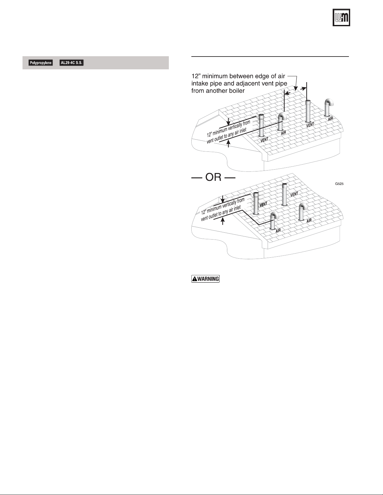
AquaBalance® SERIES 2 WALL MOUNT GAS-FIRED WATER BOILER — Boiler Manual
12 DIRECT VENT — Vertical with separate pipes (continued)
See notices on previous page.
Prepare roof penetrations
1. Air pipe penetration:
a. Cut a hole for the air pipe. Size the air pipe hole as
close as desired to the air pipe outside diameter.
2. Vent pipe penetration:
a. Cut a hole for the vent pipe. For either combustible
or noncombustible construction, size the vent pipe
hole at least 0.4” larger than the vent pipe diameter.
b. Insert a galvanized metal thimble in the vent pipe
hole.
3. Space the air and vent holes
spacings shown in Figure 25, page 22.
4. Follow all local codes and vent pipe manufacturer’s
instructions for isolation of vent pipe when passing
through floors, ceilings and roofs.
5. For Canadian installations, provide clearances required
by CSA B149.1 or B149.2 Installation Code and a
ULC S636 compliant vent kit.
6. Provide flashing and sealing boots sized for the vent
pipe and air pipe. Follow all vent pipe manufacturer’s
instructions.
no closer than the minimum
Figure 31 Terminations for multiple boilers
Termination and fittings
1. Prepare the vent termination elbow and the air termination elbow (Figure 30, page 25) by inserting bird screens.
Bird screens must be purchased separately. See the parts
list at the end of this manual for part numbers.
2. The air piping must terminate in a down-turned 180-degree return bend as shown in Figure 30, page 25. Locate
the air inlet pipe no further than 12 inches from the
center of the vent pipe. This placement avoids recirculation of flue products into the combustion air stream.
3. The vent piping must terminate in an up-turned coupling as shown in Figure 30, page 25. The top of the
coupling must be at least 12 inches above the air intake.
The air inlet pipe and vent pipe can be located in any
desired position on the roof, but must always be no further than 12 inches apart (center to center) and with the
vent termination at least 12 inches above the air intake.
4. Maintain the required dimensions of the finished termination piping as shown in Figure 30, page 25.
5. Do not extend exposed vent pipe outside of building
more than shown in this document. Condensate could
freeze and block vent pipe.
Also maintain maximum distances between the
vent and air pipes for each boiler as shown in
Figure 30, page 25.
26
Part number 550-100-325/0718
Page 27
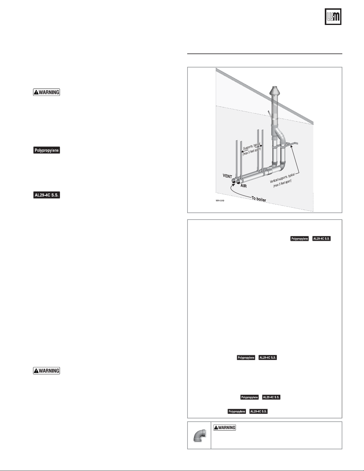
AquaBalance® SERIES 2 WALL MOUNT GAS-FIRED WATER BOILER — Boiler Manual
13 DIRECT VENT — Vertical concentric
Allowable vent/air pipe materials &
lengths
1. The concentric termination kit must be purchased separately.
Use only the vent materials and kits listed in Fig-
ure 21, page 17. Provide pipe adapters if specified.
2. Locate the termination such that the total air piping and
vent piping from the boiler to the termination will not
exceed the maximum length given in Figure 20, page 16.
3. This termination requires a 45-degree elbow that is not
supplied with the termination kit. The maximum vent/air
pipe lengths include allowance for this elbow.
For polypropylene applications, comply with
any additional requirements in the vent system
manufacturer’s instructions. (Do Not use 3” PVC
transition pieces at the boiler vent and air connections)and at the termination if using a 3” PVC
concentric vent kit. Install a locking collar at every
joint.
For AL29-4C vent pipe applications, comply with
any additional requirements in the vent system
manufacturer’s instructions. Provide a AL29-4C
starter piece from the AL29-4C manufacturer to
the transition at the boiler vent connection. Air
pipe must be PVC or CPVC. Provide a 3” PVC
transition at the boiler air connection if using 2”
air pipe. Provide transition pieces to PVC at the
vent and air pipe termination connections.
Determine termination location
Locate the concentric vent/air termination using the following
guidelines:
1. The concentric vent/air assembly must terminate as shown
in Figure 34, page 28.
2. The termination must comply with the clearances and
limitations shown in Figure 22, page 19.
3. Locate the termination so it is not likely to be damaged by
foreign objects, such as stones or balls, or subject to buildup
of leaves or sediment.
4. For Canadian installations, provide clearances required by
CSA B149.1 or B149.2 Installation Code and a ULC S636
compliant vent kit.
Multiple vent/air terminations
1. When terminating multiple boilers, install the concentric
vent/air termination assemblies as described in this manual.
All vent outlets must terminate at the same height
to avoid possibility of severe personal injury,
death or substantial property damage.
2. Place roof penetrations to obtain minimum clearance of
12 inches between the edges of adjacent vent pipes of other
boilers for U. S. installations (see Figure 33, page 28).
3. For Canadian installations, provide clearances required by
CSA B149.1 or B149.2 Installation Code and a ULC S636
compliant vent kit.
4. The air inlet of a boiler is part of a direct vent connection. It
is not classified as a forced air intake with regard to spacing
from adjacent boiler vents.
Figure 32 INSTALLATION SEQUENCE — Concentric vertical
Step 1 Read and follow all instructions in this manual. DO NOT
Step 2 Install the boiler in a location that allows proper routing of all
Step 3 Make sure the selected vertical termination location complies
Step 4 Use only the vent materials listed in Figure 21, page 17. Provide
Step 5 Vent piping and air piping lengths must not exceed the values
Step 6 The concentric termination must be assembled and installed
Step 7 Prepare the vertical penetration(s) — assemble the concen-
Step 8 Install vent and air piping between the boiler and the concen-
Step 9 Install pipe supports every 5 feet on both the horizontal and
Step 10 Install a hanger support within 6 inches of any upturn in the
proceed with vent/air installation until you have
read page 17 through page 20.
notices at left.
vent and air piping to the selected sidewall location.
with Figure 22, page 19. (Multiple boiler concentric terminations must also comply with Figure 33, page 28.)
pipe adapters where required.
shown in Figure 20, page 16.
before piping from the boiler to the termination.
tric termination kit and secure the penetration components
as instructed in this section. Provide the supports indicated
and mount the termination assembly. See “Prepare roof penetrations” on page 28 and “Mount concentric termination”
on page 28.
tric vent/air termination. Slope horizontal piping downward
toward the boiler at least 1/4 inch per foot. See page 30 for
general guidelines.
vertical runs.
piping.
USE SWEEP ELBOWS FOR ALL VENT AND
See notices at left.
See notices at left.
See notices at left.
AIR PIPING — DO NOT use short radius elbows
for vent or air piping. Boiler performance could be
affected.
See
Part number 550-100-325/0718
27
Page 28
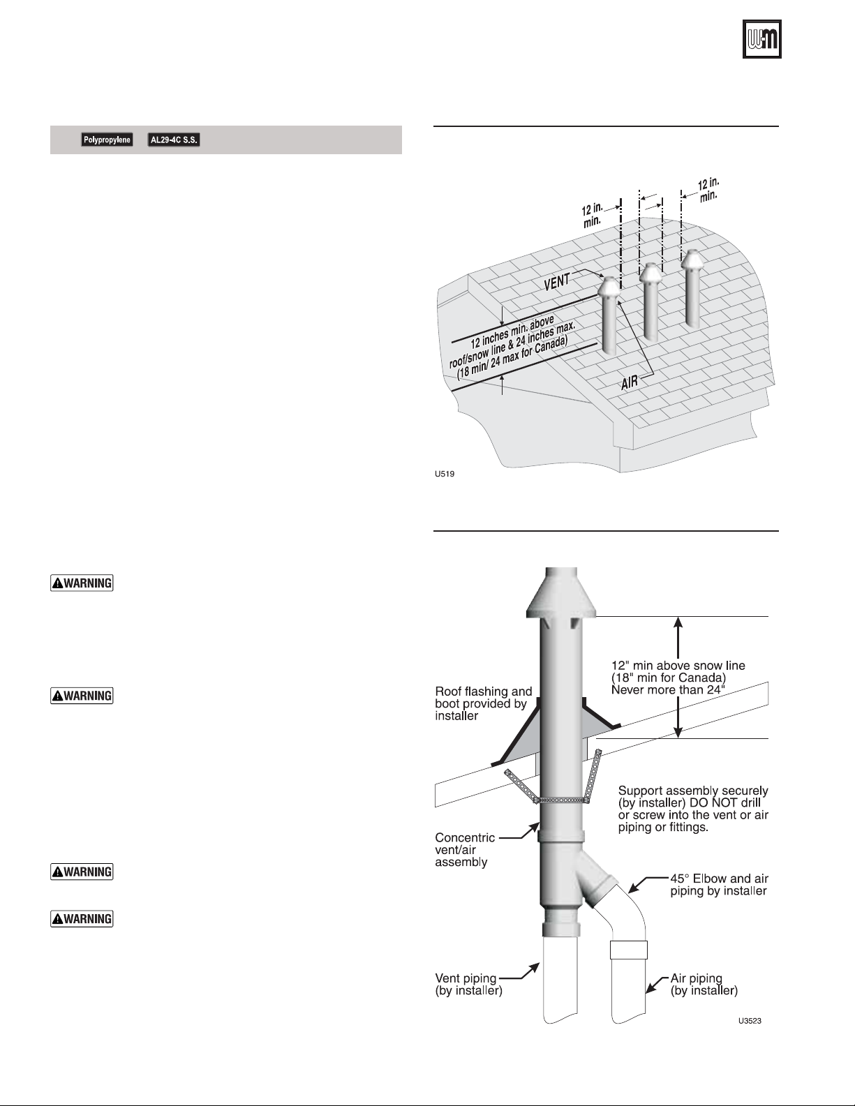
AquaBalance® SERIES 2 WALL MOUNT GAS-FIRED WATER BOILER — Boiler Manual
13 DIRECT VENT — Vertical concentric (continued)
See notices on previous page.
Prepare roof penetrations
1. Roof penetration hole:
a. Cut a clearance hole to clear the termination outside di-
ameter as prescribed in the kit instructions.
b. Insert a galvanized metal thimble in the vent pipe hole.
2. Follow all local codes for isolation of vent pipe when passing
through floors, ceilings and roofs.
3. For Canadian installations, provide clearances required by
CSA B149.1 or B149.2 Installation Code and a ULC S636
compliant vent kit.
4. Provide flashing and sealing boots sized for the concentric
termination outside diameter.
Mount concentric termination
1. Assemble the vent termination as described for concentric
terminations, on page 29.
2. Mount the termination as shown in Figure 34.
3. Support the concentric vent/air termination at the roof penetration as shown in Figure 34 or per concentric kit instructions.
• The supports/bracing used must support the termina-
tion assembly to prevent vertical slippage or sideways
movement.
• The clamps used on the outside of the termination pipe
must not cut into the pipe or contain sharp edges that
could cause a crack to form.
The vent and air piping must be securely supported,
and must not rest its weight on the boiler fittings.
DO NOT drill or screw into either the vent pipe or
air pipe. Failure to properly support the vent and air
piping could result in vent piping damage, resulting
in possible severe personal injury, death or substantial property damage.
When inserting the partially-assembled termina-
tion kit through the roof penetration, wrap plastic
or other protection over the end of the exposed
assembly to prevent debris from entering the pipes.
If the air passages become blocked, the boiler will
not operate. Once the rain cap has been cemented
to the assembly, there is no way to correct the problem. The assembly would have to be replaced if it
were cut to be removed and cleaned. Altering the
assembly in any way could result in severe personal
injury or death due to toxic flue product emissions.
Figure 33 Vertical termination — 3” PVC concentric —
single or multiple boilers
Figure 34 3” PVC concentric termination supports
If using AL29-4C stainless vent pipe, use the vent
pipe manufacturer’s PVC adapter if connecting to
a PVC concentric vent attachment.
Do not connect any other appliance to the vent pipe
or multiple boilers to a common vent pipe.
4. After the assembly has been positioned in the roof opening and
all supports have been attached, install a bird screen (purchased
separately if not included with the kit) and rain cap as follows:
a. Place the bird screen on the end of the inner pipe as in
Figure 35, page 29, or per kit instructions for polypropylene kits.
b. Cement the rain cap in place.
28
Part number 550-100-325/0718
Page 29
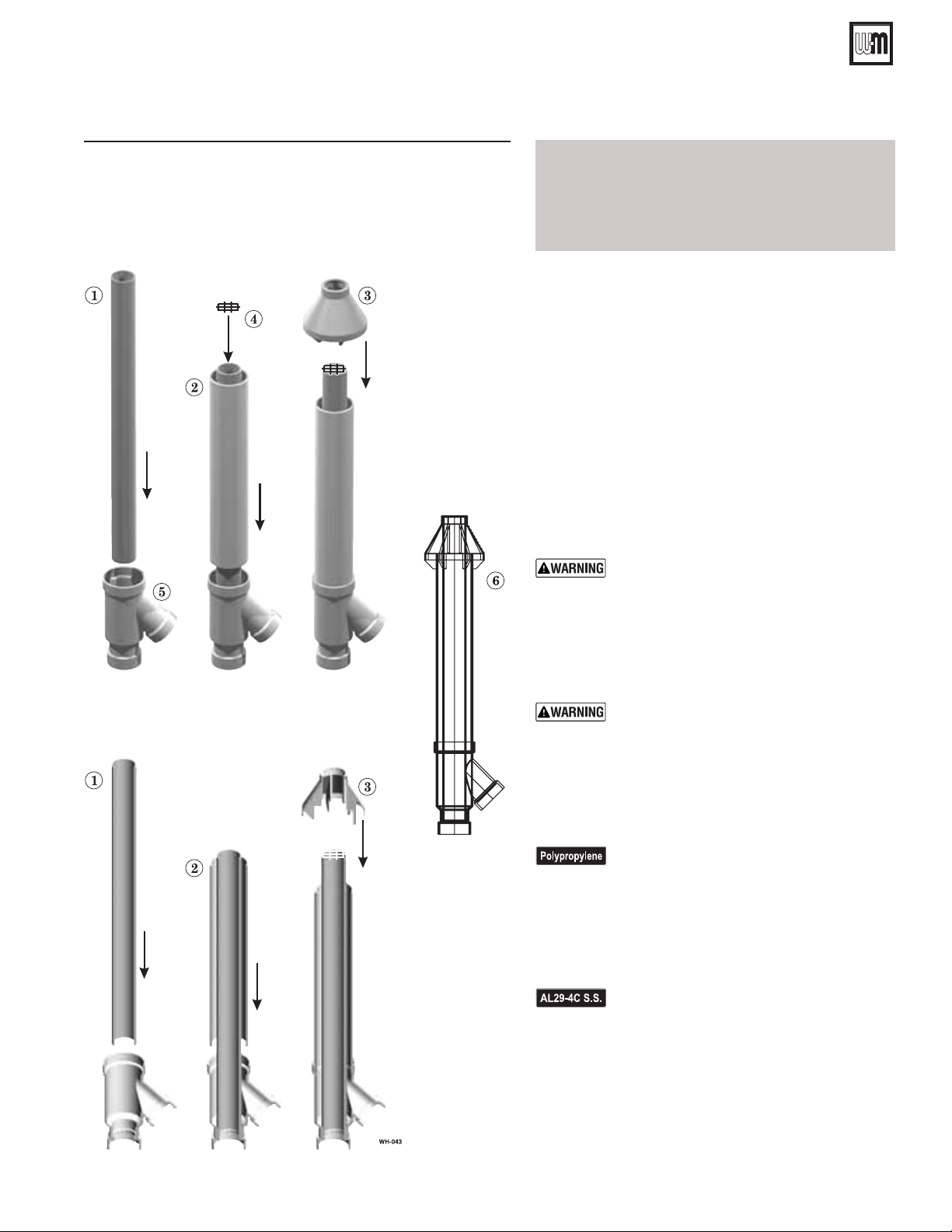
AquaBalance® SERIES 2 WALL MOUNT GAS-FIRED WATER BOILER — Boiler Manual
14 Concentric termination, typical (sidewall or vertical)
Figure 35 PVC concentric termination assembly — DO NOT
attach the rain cap until the termination has been
inserted through the roof or wall and all supports
have been installed. See LEGEND at right. See kit
instructions for details of polypropylene kits.
LEGEND for Figure 35
1 — Inner PVC pipe (vent)
2 — Outer PVC pipe (air)
3 — Rain cap
4 — Bird screen
5 — Y fitting
6 — Finished assembly
Assembling concentric termination
1. Follow all instructions provided with the concentric
termination kit. The following are general guidelines
for information only.
2. See Figure 35, for the typical assembly of a concentric
termination assembly.
3. Prepare the bird screen, item 4 (purchase separately if
not included with the kit). Cut the bird screen to size
if required. If the bird screen must be trimmed, cut the
bird screen to fit the outside diameter of the PVC inner
pipe supplied with the termination kit.
4. Partially assemble the vent termination kit in the sequence shown in Figure 35, or per the concentric kit
instructions.
DO NOT install the rain cap and bird screen
until the assembly has been inserted through
the roof (or sidewall) and all supports have
been installed. Follow instructions to cover
the end of the assembly with plastic before
inserting through the roof penetration to
prevent debris from blocking the air passages.
If necessary, you can shorten the lengths of the
inner and outer pipes for a shorter finished
assembly. But you must ensure the pipes butt
correctly at both ends. Failure to properly assemble the concentric termination can result
in flue gas recirculation, causing possible
severe personal injury or death.
For polypropylene applications, comply
with any additional requirements in the vent
system manufacturer’s instructions. (Do Not
use 3” PVC transition pieces at the boiler vent
and air connections) and at the termination
if using a PVC concentric vent kit.
locking collar at every joints.
For AL29-4C vent pipe applications, comply
with any additional requirements in the vent
system manufacturer’s instructions. Provide
a AL29-4C starter piece from the AL29-4C
manufacturer to the transition at the boiler
vent connection. Air pipe must be PVC or
CPVC. Provide a 3” PVC transition at the
boiler air connection if using 2” air pipe.
Provide transition pieces to PVC at the vent
and air pipe termination connections.
Install a
Part number 550-100-325/0718
29
Page 30
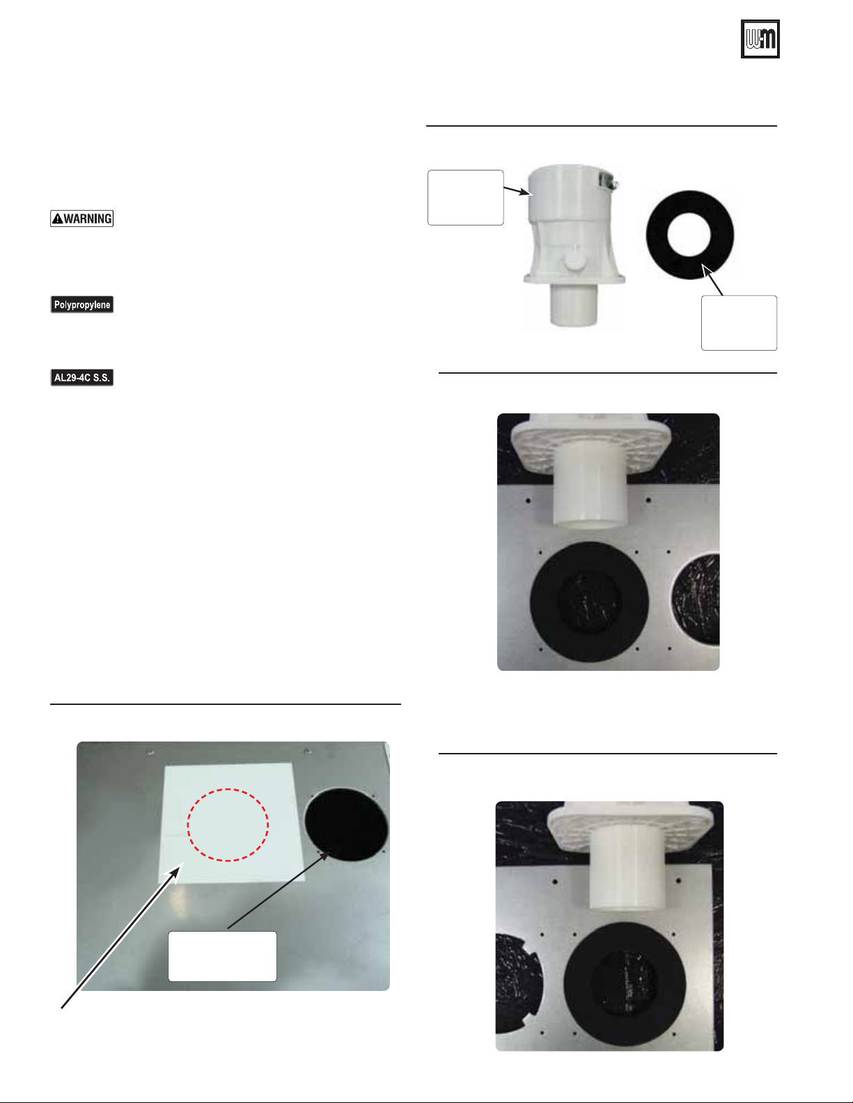
AquaBalance® SERIES 2 WALL MOUNT GAS-FIRED WATER BOILER — Boiler Manual
15 Vent and air piping and boiler connections
Follow termination instructions
1. Read and follow all instructions for the termination type
used before proceeding with this page. Follow all instructions
provided by vent pipe manufacturer.
Use only materials from the manufacturers listed
in Figure 21, page 17.
Installing vent and air piping
For polypropylene applications, comply with any
additional requirements in the vent system manufacturer’s instructions. (Do Not use 3” PVC transition pieces at the boiler vent and air connections).
For AL29-4C vent pipe applications, comply with
any additional requirements in the vent system
manufacturer’s instructions.
1. Work from the boiler to vent or air termination. Do not
exceed the lengths given in the previous pages for either the
air or vent piping.
2. See Figure 36, for locations for attaching vent and air inlet
adapters on to the boiler. Air inlet adapter connection is made
on right side of centered flue adapter.
3. Remove vent/exhaust protective paper prior to mounting
vent adapter.
4. Vent and air inlet adapters needed to be attached to top
securely with four (4) 10-32 large Phillips head screws, see
Figures 38, 39 and 40. Vent adapters (provided with boiler)
are for polypropylene, PVC, and AL29-4C venting.
5. See Figure 38, center flue gasket and insert the extruded flue
vent adapter into the center opening, secure with four (4)
10-32 Phillips head screws.
Figure 36 Boiler top opening (out of the carton)
Figure 37 Flue and vent adapter and gasket
Vent
adapter
Vent
gasket
Figure 38 Vent flue adapter into top flue center opening
6. See Figure 40, right air inlet, center gasket and air inlet vent
adapter over right opening, secure with four (4) 10-32 Phillips head screws.
vent/exhaust
location
Air pipe
connection
Remove protective paper.
30
Figure 39 Vent (air inlet) adapter inserted into top right
opening
Part number 550-100-325/0718
Page 31
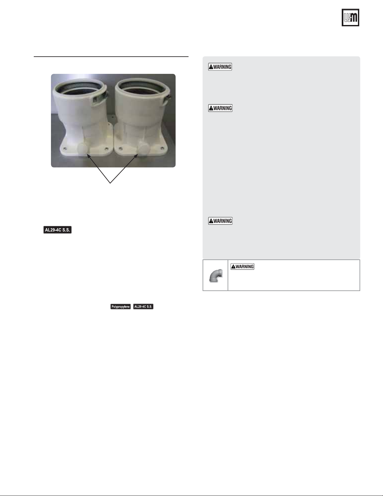
AquaBalance® SERIES 2 WALL MOUNT GAS-FIRED WATER BOILER — Boiler Manual
15 Vent and air piping and boiler connections (continued)
Figure 40 Vent (flue) and air adapters in place
Vent and Air adapters to be installed with test ports facing to
front of boiler. Must be locked closed.
7. The adapter accepts 3” PVC, CPVC, Polypropylene and
AL29-4C material. Use a 2” adapter (AB-80/120 only), if
needed.
with any additional requirements in the vent system manu facturer’s instructions. Provide a AL29-4C starter piece
from the AL29-4C manufacturer to the transition at the
boiler vent connection.
8. Cut pipe to required lengths.
9. Dry assemble entire vent or air piping to ensure proper fit
before assembling any joint.
10. Maintain minimum clearance of
pipe and any combustible wall or material.
11. Assembling PVC or CPVC: (
manufacturer’s instructions for preparation and assembly)
a. Deburr inside and outside of pipe ends.
b. Chamfer outside of each pipe end to ensure even cement
c. Clean all pipe ends and fittings. Dry thoroughly.
d. For each joint:
• Handle fittings and pipes carefully to prevent con
• Apply primer liberally to both joint surfaces — pipe
• While primer is still damp, lightly apply approved
• Apply a second coat to both surfaces. Avoid using
• With cement still wet, insert pipe into fitting, twist
• Wipe excess cement from joint. Check joint to be
12. Seal wall or floor penetration openings following local code
requirements.
For AL29-4C vent pipe applications, comply
3/16 inch between vent
— follow pipe
distribution when joining.
tamination of surfaces.
end and fitting socket.
cement to both surfaces in a uniform coating.
too much cement on sockets to prevent cement
buildup inside.
ing ¼ turn. Make sure pipe is fully inserted.
sure a smooth bead of cement shows around the
entire joint.
ADAPTERS — Use adapters if using 2-inch pipe,
(AB-80/120 only)
1. Clean and deburr inside and outside of both ends of air and vent
pipes. Chamfer boiler end of vent pipe for ease of insertion.
The vent pipe end must be smooth and chamfered to
prevent possible damage to sealing gasket in vent pipe
adapter.
2. Inspect vent or air adapter (above) — verify no obstructions or
foreign objects inside.
3. Loosen clamp screw (if used).
4. Measure 2¼-inches from end of pipe and make a mark with felttip pen.
5. Apply small amount of silicon grease to end of pipe to ease inser
tion.
6. Insert pipe into adapter.
7. Slide pipe down until the 2¼-inch mark is reached.
Do not apply excessive force or bend the adapter or
flue/air pipe when inserting. The adapter or seal could
be damaged. If any portion of the vent or air system is
damaged, it must be replaced.
8. The seal is accomplished with the internal gasket.
USE SWEEP ELBOWS FOR ALL VENT
AND AIR PIPING — DO NOT use short radius
elbows for vent or air piping. Boiler performance
could be affected.
-
-
-
Part number 550-100-325/0718
31
Page 32
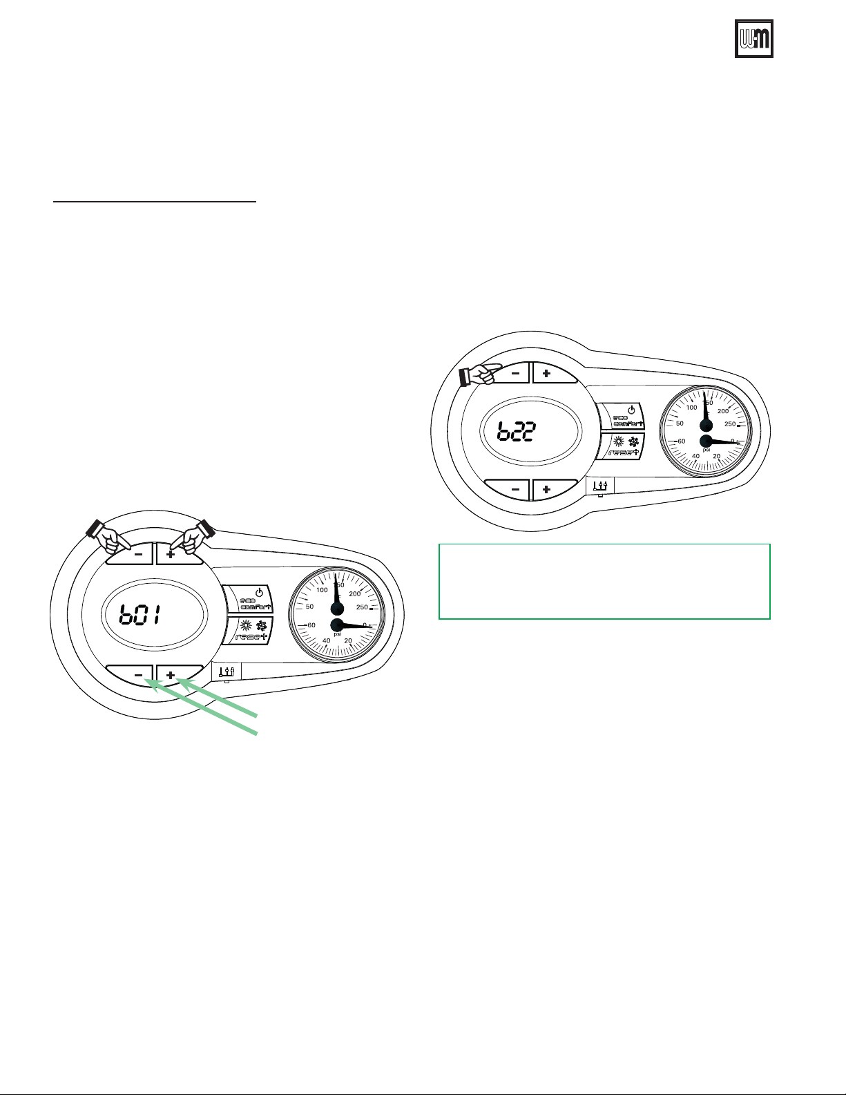
AquaBalance® SERIES 2 WALL MOUNT GAS-FIRED WATER BOILER — Boiler Manual
15 Vent and air piping and boiler connections (continued)
Control selection for vent material
Perform at start-up final checks
-
Venting Material Change “b22” parameter
See Figure 124, page 97 (boiler default is “1”for PVC vent
material)
If other vent material is used, you program that material via
the control board.
To insure proper boiler operation (Combi and Heating Only
boilers) the boiler control programmed default is for PVC
venting material. You MUST program the boiler control for
any other venting material that you installed other than PVC,
in order to improve operational efficiency.
Refer to “Quick Start Guide” page 69, to first power up the
boiler.
To access the configuration menu:
Push DHW buttons + & -
together for 10 seconds
For example: CPVC, Polypropylene, or AL29-4C stainless
steel.
“b22” parameter
PVC solid core, ....................................... Select: “1”
CPVC only, ............................................. Select: “2”
Polypropylene and AL29-4C, ................ Select: “0”
Use the DHW + or – buttons to
modify the parameter value
DHW
DHW
Press Heating
buttons + & - to
scroll up or down
the parameter
numbers
1. Press the DHW + and DHW – buttons together for 10
seconds.
2. At the end of the 10 seconds the display will show the message “b01”.
3. Press the heating buttons (+ or -) to scroll up or down
the list of parameters in increasing or decreasing order to
parameter “b22”.
4. Press the DHW buttons (+ or -) to view or modify the value
of a parameter: the modification will be automatically saved.
Exiting the “User interface setting” menu. Press the “DHW +”
and “DHW -” buttons together for 10 seconds; or switch the
power to the unit o and then on again; or wait for automatic
exiting which occurs aer two (2) minutes
32
Part number 550-100-325/0718
Page 33
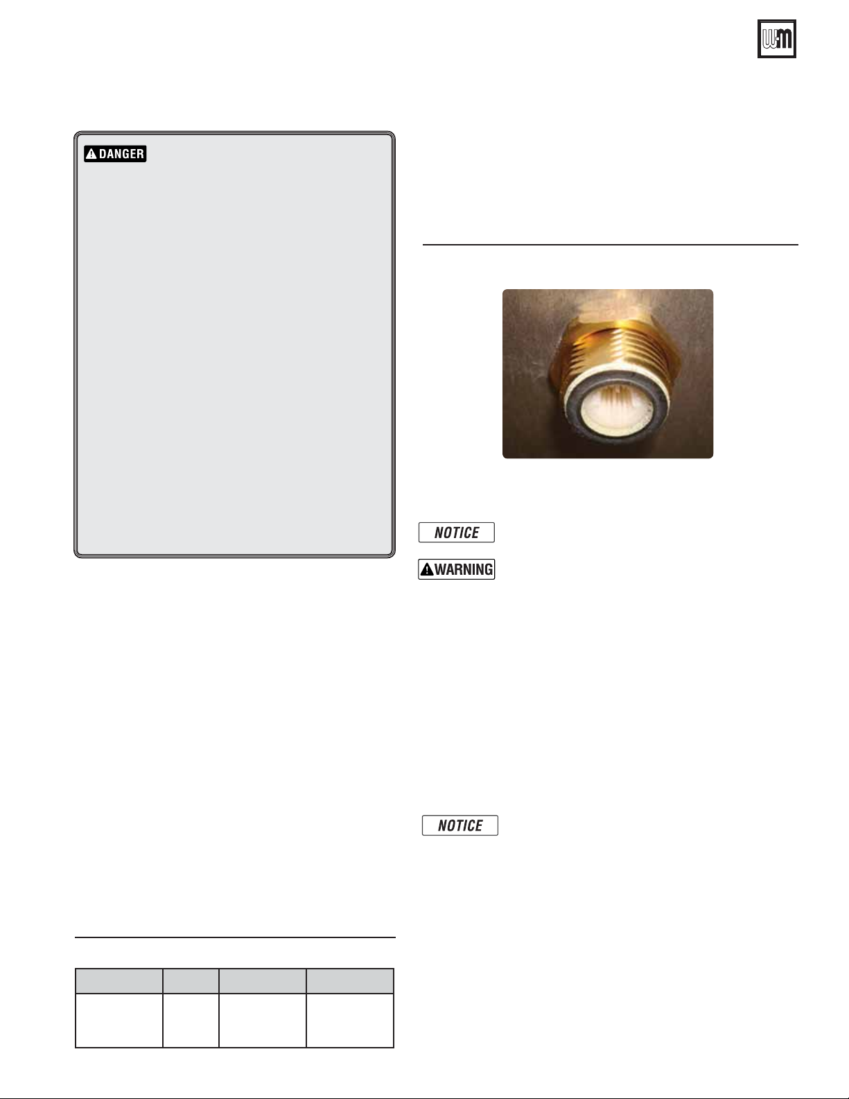
AquaBalance® SERIES 2 WALL MOUNT GAS-FIRED WATER BOILER — Boiler Manual
16 Install water piping
Domestic Water Piping – Combi Boiler
Hot Water Can Scald!
• Consumer Product Safety Commission and some
states recommend domestic hot water temperature of 130°F or less.
• When installing an
selection and installation must comply with valve
manufacturer’s recommendations and instructions.
• Water heated to a temperature suitable for clothes
washing, dish washing and other sanitizing needs
will scald and cause injury.
• Children, elderly, infirm or physically handicapped persons are more likely to be injured by
hot water. Never leave them unattended in or near
a bathtub, shower or sink. Never allow small children to use a hot water faucet or draw their own
bath. If anyone using hot water in the building
fits this description, or if state laws or local codes
require certain water temperatures at hot water
faucets, take special precautions:
• Install
• Use lowest practical temperature setting.
• Check water temperature immediately after first
If the boiler piping system is connected to heating coils
located in air handling units where there may be exposed
to refrigerated air circulation then it must be equipped
with flow control valves or other automatic means to
prevent gravity circulation of the boiler water during the
cooling cycle.
automatic mixing valve set according to
those standards.
heating cycle and after any adjustment.
To pipe DHW, see Figure 43, page 34
1. Size piping for DHW inlet and outlet - 1/2” NPT on
80/120 and 3/4” NPT on the 155 boilers.
2. Additional anti-scald devices may be installed at each
hot water faucet, bath and shower outlet.
3. In hard water areas, soften cold domestic supply water
to heaters to prevent scale build-up.
4. Refer to Figure 41, below for maximum and minimum
domestic water pressure rating for our units, on the
domestic pipes (Combi only).
5. A new approved pressure relief valve that complies with
the standard for relief valves and automatic gas shut-off
devices for Hot Water Supply Systems, ANSI Z21.221
CSA4.4 is required to be installed at the supply DHW
connection (field supplied). This pressure relief valve
Figure 41 Domestic water pressure rating
DHW
Pressure
Rating
automatic mixing valve,
Minimum Maximum
PSIG 4.5 130
should be capable of at least the Maximum input of the boiler
and Maximum pressure Not exceeding 130 PSIG. The pressure
relief valve’s discharge should be per instructions in the Warning
box, page 38. DO NOT place any other type valve or shut-off device
between the relief valve and the boiler. The pressure relief valve
must be manually checked once a year to verify correct operation.
*(80 KBTU/hr, 120 KBTU/hr, or 155 KBTU/hr, depending on the
boiler model).
Figure 42 DHW inlet has a filter screen - Port 4 - see
Figure 43, page 34
6. Combi Boiler: Domestic water inlet connection showing filter
screen to protect paddle flow switch from sand and other
debris.
Pipe in a “union” fitting below this adapter to service
this filter screen.
Use two wrenches when tightening water piping at
boiler, using one of the wrenches to prevent the boiler
interior piping from turning (wrench on both sides,
here and inside boiler). Failure to support the boiler
piping connections to prevent them from turning
could cause damage to boiler components.
• Thermostatic Mixing Valve - A mixing valve (for regulating
domestic heating water) must be used to regulate the water temperature leaving the plate heat exchanger. NOTE: the valve must be set to
supply a domestic water temperature of not more than 120 degrees F. It
is the responsibility of the installer to set the valve and remove the dial.
• DHW Filter- Installation of a 100 micron or lower water filter at
the entrance of the DHW connection to protect the DHW flow
switch. Failure to install the DHW water filter from dirt and debris
will cause it to malfunction.
Check Valve – A check valve must be field provided
and installed on the outlet of the mixing valve to
prevent expansion devices downstream from back
flowing when the water pressure drops during cold
water draws. Failure to prevent the backflow will cause
water to flow through the flow switch, activating it,
when the cold water draw has ended and the water
pressure increases.
• Drain and Isolation Valves- Install drain and isolation valves on the
inlet and outlet of the DHW connections so that the DHW heat
exchanger can be flushed and cleaned from possible build-up caused
by dirty or hard water, which is a maintenance requirement.
• Hard Water- To prevent the formation of scale on the inside of the
plate DHW heat exchanger and other components in the domestic
hot water system, water with hardness higher than 50 ppm Calcium
*
Part number 550-100-325/0718
33
Page 34
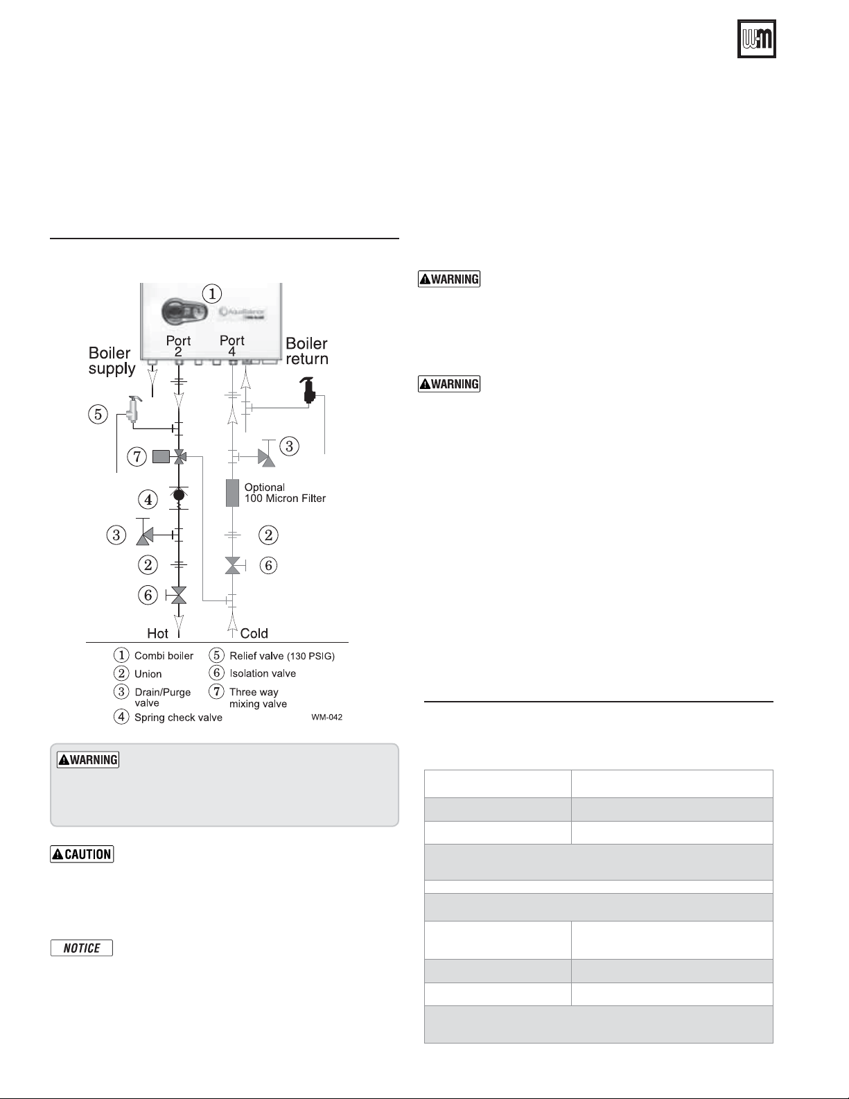
AquaBalance® SERIES 2 WALL MOUNT GAS-FIRED WATER BOILER — Boiler Manual
16 Install water piping (continued)
Carbonate must be treated with a “Water Softener” prior
to entering the boiler. Plugging of the domestic system by
scaling or accumulation of dirt is not the responsibility of
Weil-McLain, and suitable steps must be taken to avoid it.
• Cleaning- refer to the installation manual maintenance
section for the proper cleaning procedure for the plate
DHW heat exchanger, and the required cleaning frequency.
Figure 43 Domestic Piping - Brazed Plate Heat
Exchanger - Ports 2 and 4
Additional limit controls
Following standard industry practices, if installation is to comply
with ASME or Canadian requirements, an additional high temperature limit may be needed. Consult local requirements for other
codes/standards to determine if needed.
1. Install a manual reset high temperature limit to prevent a
temperature above 200°F in system supply piping between
boiler and isolation valve. (Note that the control operating
limit function shuts the boiler down at 195°F, or lower if set
to a lower value.)
Multi-temperature systems — If the heating sys-
tem includes circuits that require lower temperature
water (radiant slab circuits, for example) as well as
higher temperature circuits, it is recommended to
protect low temperature circuits with limit controls
that are wired to the control external limit circuit
terminals.
Low temperature systems — If using temper-
ature-limited materials (such as PEX tubing) in
system piping, it is recommended to protect the
system with limit controls that are wired to the
controls external limit circuit.
2. See instructions beginning on page 48, for wiring information.
3. If using a manual reset limit control or wiring in the manual
reset circuit, set boiler control limit at least 20°F less than the
external manual reset limit (i.e., set control no higher than
180°F for a 200°F external limit, for example).
Studies have indicated that dangerous bacteria
can form in potable water distribution systems
if certain minimum water temperatures are not
maintained. Contact local health department for
more information.
This boiler is NOT intended for connection with a
refrigeration system.
General piping information
Additional controls, if required
The control uses temperature sensors to provide
both high limit protection and modulating
temperature control.
function requires manual reset
jurisdictions may require additional external
controls for high limit and/or low water cutoff
protection.
The control’s high limit
. Some codes/
Backflow preventer
Use backflow preventer in the cold water supply piping if required by local codes.
System/zone pipe sizing
(Baseboard, convectors or cast iron radiators ONLY)
For residential space heating applications (other than radiant
heating or unit heaters) ONLY, you can use the sizing suggestions
in Figure 44.
Figure 44 Suggested pipe sizing for system headers
and zone piping — RESIDENTIAL with
baseboard, convectors or cast iron radiators
ONLY (20°F temperature rise)
Model
AB-80/120 1” or larger
AB-155 1-1/4” or larger
Recommendations are based on a 20°F temperature drop
through the system.
Suggested maximum load per zone
Copper pipe and
baseboard size
¾” 67
1” 104
Size zone circulators to handle the required flow and head
loss for each zone.
System header
Maximum recommended
feet of baseboard
34
Part number 550-100-325/0718
Page 35
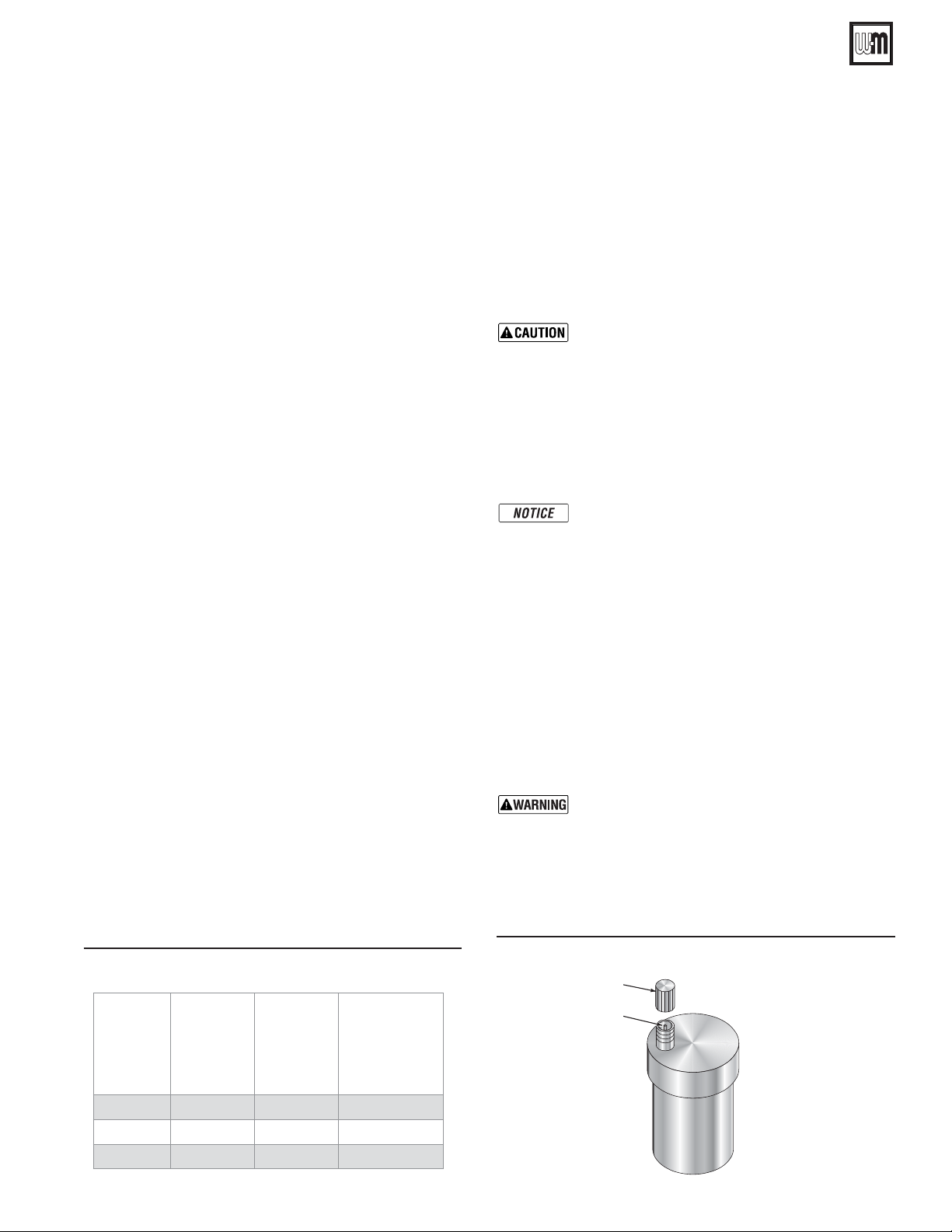
AquaBalance® SERIES 2 WALL MOUNT GAS-FIRED WATER BOILER — Boiler Manual
17 Primary/Secondary System Piping
System water piping methods
Primary/secondary piping to boiler
Using primary/secondary piping will provide the most efficient
and reliable operation of the boiler and the heating system.
1. Use information beginning on page 35 to size pump for
proper flow through the boiler.
2. Reference suggested piping layouts on pages 36-41.
System water piping methods
Near boiler piping
1. Connect boiler to system only as shown in Figure 47, page 36.
The primary/secondary piping shown ensures the boiler
loop will have sufficient flow.
2. Install a system circulator or zone circulators as shown in the
piping diagrams in the Primary/Secondary System Piping
section in this manual. These circulators must be supplied
by the installer.
System or zone circulators flow rates
1. Size circulators based on the flow rate required to achieve the
temperature drop required. You can closely estimate temperature rise (or drop) through a circuit by using the following
formula, where TD is temperature rise (or drop), FLOW is
flow rate (in gpm), and BTUH is the heat load for the circuit:
BTUH
FLOW =
Examples:
1. Consider a system loop for a system with total heating load
equal to 143,000 Btuh. The desired temperature drop through
the system piping is 20°F. Then the required flow rate is:
FLOW =
SIMPLIFIED:
For 20° temperature drop, FLOW = MBH / 10.
System or zone circulator head requirement
1. The circulator must be capable of delivering the required
flow against the head loss that will occur in the piping.
2. Determine the pipe size needed and the resultant head
loss using accepted engineering methods.
—–—–—–—–
TD x 500
143,000
—–—–—–—–
20 x 500
= 14 gpm
Expansion Tank Location
Figure 47, page 36 show typical installation of the system expansion
tank. It is highly recommended that you locate the air separator
and expansion tank as shown in the suggested piping drawings
on pages 35 - 37.
Ensure that the expansion tank size will handle boiler and system
water volume and temperature. See tank manufacturer’s instructions and ratings for details. Additional tanks may be added to the
system if needed to handle the expansion. These tanks may be
installed by connecting to tees in the system piping.
Undersized expansion tanks cause system water to
be lost from the relief valve and makeup water to be
added through the fill valve. Eventual boiler failure
can result due to excessive make-up water addition.
Always locate the cold-water fill connection at the
expansion tank. Never locate this elsewhere.
Diaphragm- or bladder-type tank:
Refer to Figure 49, page 37 for suggested piping when using a
diaphragm- or bladder-type expansion tank.
Diaphragm- or bladder-type expansion tank—
Always check pressure and charge tank with tank
removed from system to be sure reading is accurate.
Boiler relief valve is set for 30 PSIG. Operating pres-
sure of system, after temperature expansion above
cold fill pressure, should not exceed 24 PSIG to avoid
weeping of relief valve.
Install an automatic air vent on top of the air separator, per separator manufacturer’s instructions.
Automatic air vents (if used — automatic air
vents must be used with diaghragm-type expansion
tanks only)
1. Remove the cap from any automatic air vent in the system
and check operation by depressing valve “B” slightly with the
tip of a screwdriver.
Scald hazard — Water from air vent may be very
hot. Avoid contact to prevent possible severe personal injury.
2. If the air vent valve appears to be working freely and not leaking, replace cap “A”, twisting all the way on.
3. Loosen cap “A” one turn to allow vent to operate.
4. Have vent replaced if it does not operate correctly.
Figure 45 Maximum and minimum flow rates through
boiler heat exchanger
Boiler
Model
AB-80
AB-120
AB-155
Part number 550-100-325/0718
MAX
Flow Rate
20° F
temperature
rise
GPM
7.9 2.9 2.3
12.0 4.3 3.4
15.2 6.1 4.5
MIN
Flow Rate
50° F
temperature
rise
GPM
Flow Rate
Delta T1
protection
67° F
temperature
rise
GPM
Figure 46 Automatic air vent
A
B
85036
35
Page 36
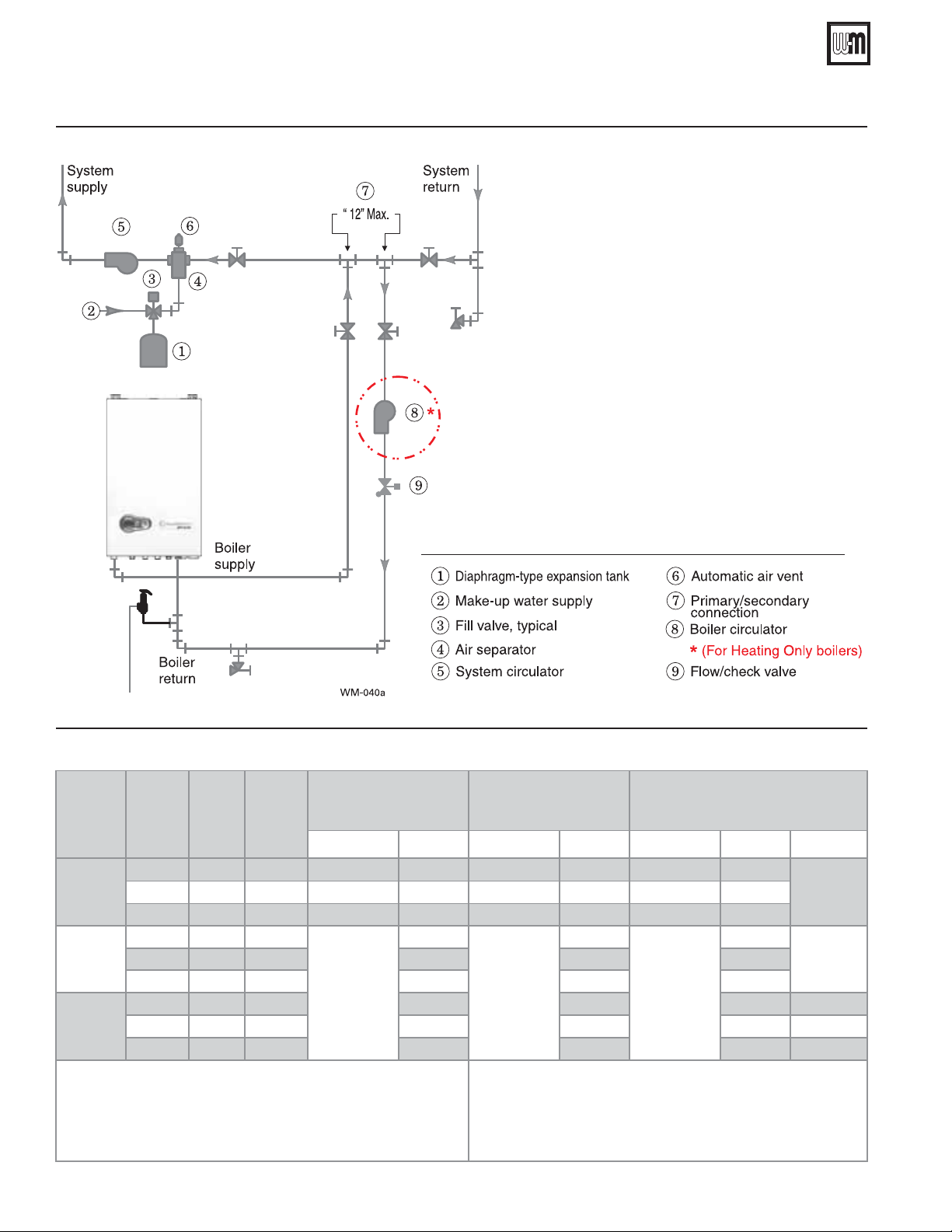
AquaBalance® SERIES 2 WALL MOUNT GAS-FIRED WATER BOILER — Boiler Manual
17 Primary/Secondary System Piping (continued)
Figure 47 Piping to diaphragm (or bladder) expansion tank
Figure 48 Pressure drop through AquaBalance
Boiler
Model
AB-80
HEAT
ONLY
AB-120
HEAT
ONLY
AB-155
HEAT
ONLY
BOILER
dT
(ºF)
(GPM)
92%
Eff.
20 7.4 7.8 12.5 3.0 20.3 10.8 A B,C,D
40 3.7 2.7 3.5 0.8 6.2 3.5 B,C,D,E B,C,D,E
20 11.0 14.4
40 5.5 4.6 1.8 6.4 B,C,D,E
20 14.3 35.6 9.6 45.8 --- ---
30 9.5 16.4 4.6 21.0 F F
40 7.1 9.2 2.8 12.0 A,B,D A,B,D
@
Boiler
Head
Loss
(ft. w.c.)
Piping Est. Head Loss Ft. (Typical Near Boiler)
3/4” Pipe 1” Pipe 3/4” Pipe 1” Pipe 3/4” Pipe 1” Pipe 1-1/4” Pipe
Not
Recommended
Notes:
1. Operating point with current Grundfos pump inside
the boiler.
2. Combi pump included in the boiler is sized properly
for boiler loop.
®
80/120/155 heat exchanger (graphs and table)
Total Loss - Ft.
(Boiler + Near Boiler
Piping)
6.0
Not
Recommended
Circulator Legend:
B - Taco 0015
C - Grundfos UPS 15-58
D - B&G NRF 25
E - Taco 007
F - Taco 0011
20.4
Not
Recommended
A - Taco 0014
Recommended
Circulators
___30 4.9 4.0 6.0 1.5 10.0 5.5 B,C,D,E B,C,D,E
A,F
___30 7.3 7.5 3.0 10.5 B,C,D
36
Part number 550-100-325/0718
Page 37
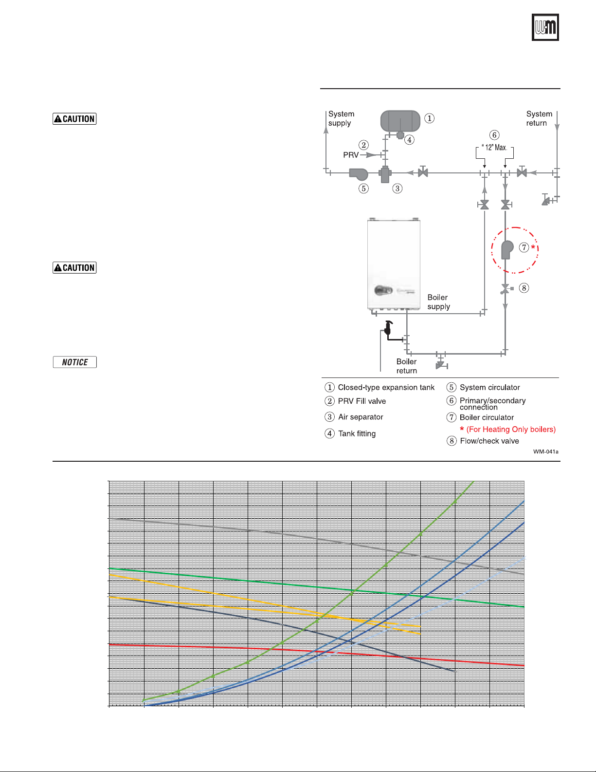
AquaBalance® SERIES 2 WALL MOUNT GAS-FIRED WATER BOILER — Boiler Manual
17 Primary/Secondary System Piping (continued)
Closed-type expansion tank:
DO NOT use a closed-type tank if connecting to a
water heater that is equipped with an automatic air
vent.
Figure 49, shows suggested piping when using a closed-type expansion tank, in which the air is directly in contact with tank water.
Connect piping (½” or ¾”) from the air separator outlet to the
tank fitting. Slope any horizontal piping a minimum of 1 inch per
5 feet of horizontal pipe.
Always use a tank fitting such as the B&G Tank-trol or Taco Tacotrol (shown). The fitting reduces gravity flow of water in the piping to the tank, avoids air bubbling through the tank water, and
provides the proper fill height in the tank.
Correct all leaks in the system or tank piping. Leaks
allow air to escape from the system and will cause
water-logging of the tank. This will result in water
loss through the boiler relief valve due to overpressurization. NEVER use an automatic air vent
in a system equipped with a closed-type expansion
tank. The air removed from the system will cause
water-logging of the expansion tank.
Closed-type expansion tank—Follow tank manufac-
turer’s instructions for filling the tank. Typical tank
sizing provides for approximately 12 PSIG when the
tank is filled to the normal level and system water is
cold. Note that boiler relief valve is set for 30 PSIG.
Operation pressure of system, after temperature
expansion above cold fill pressure, should not exceed
24 PSIG to avoid weeping of relieve valve.
Figure 49 Piping to closed-type expansion tank
Graph 1 Pressure drop through AquaBalance® 80/120/155 heat exchanger
36
1 = Boiler Pressure Drop with 3/4'' near boiler piping (80KBTU and120 KBTU)
34
2 = Boiler Pressure Drop with 1'' near boiler piping (80KBTU and120 KBTU)
32
3 = Boiler Pressure Drop with 1 '' near boiler piping (155 KBTU)
4 = Boiler Pressure Drop with 1 1/4'' near boiler piping (155 KBTU)
30
Total Head - feet water
28
26
24
Ta co 0 01 4
22
20
18
B&G NRF 25 (High)
16
14
12
Ta co 0 07
10
8
6
4
2
0
0123456789101112
Taco 0015 (High)
Grundfos UPS 15-58
(High)
Flow - gpm
Taco 0011
Part number 550-100-325/0718
1
3
4
2
37
Page 38

AquaBalance® SERIES 2 WALL MOUNT GAS-FIRED WATER BOILER — Boiler Manual
17 Primary/Secondary System Piping (continued)
Install relief valve
1. Install relief valve in 1 ” x 1” x ¾” (for AB-80/120) or 1-1/4 ” x 1-1/4” x
¾” (for AB-155) tee piped from boiler return (Figure 5, page 9).
2. Pipe the relief valve only as shown, in the location shown.
3. Connect discharge piping to safe disposal location, following guidelines
WARNING below.
in the
To avoid water damage or scalding due to relief
valve operation, as per local or state codes
Install relief valve ONLY with the spindle vertical, as
shown in illustrations in this manual.
Discharge line must be connected to relief valve out-
let and run to a safe place of disposal. Terminate the
discharge line in a manner that will prevent possibility
of severe burns or property damage should the valve
discharge. Locate away from the top of the boiler.
:
Discharge line must be as short as possible and be the
same size as the valve discharge connection throughout
its entire length.
Discharge line must pitch downward from the valve and
terminate at least 6” above the floor drain where any
discharge will be clearly visible.
The discharge line shall terminate plain, not threaded,
with a material serviceable for temperatures of 375 °F
or greater.
Do not pipe the discharge to any place where freezing
could occur.
No shutoff valve shall be installed between the relief valve
and boiler, or in the discharge line. Do not plug or place
any obstruction in the discharge line.
Test the operation of the valve after filling and pres-
surizing system by lifting the lever. Make sure the valve
discharges freely. If the valve fails to operate correctly,
replace it with a new relief valve.
Failure to comply with the above guidelines could result
in failure of the relief valve to operate, resulting in possibility of severe personal injury, death or substantial
property damage.
38
Part number 550-100-325/0718
Page 39
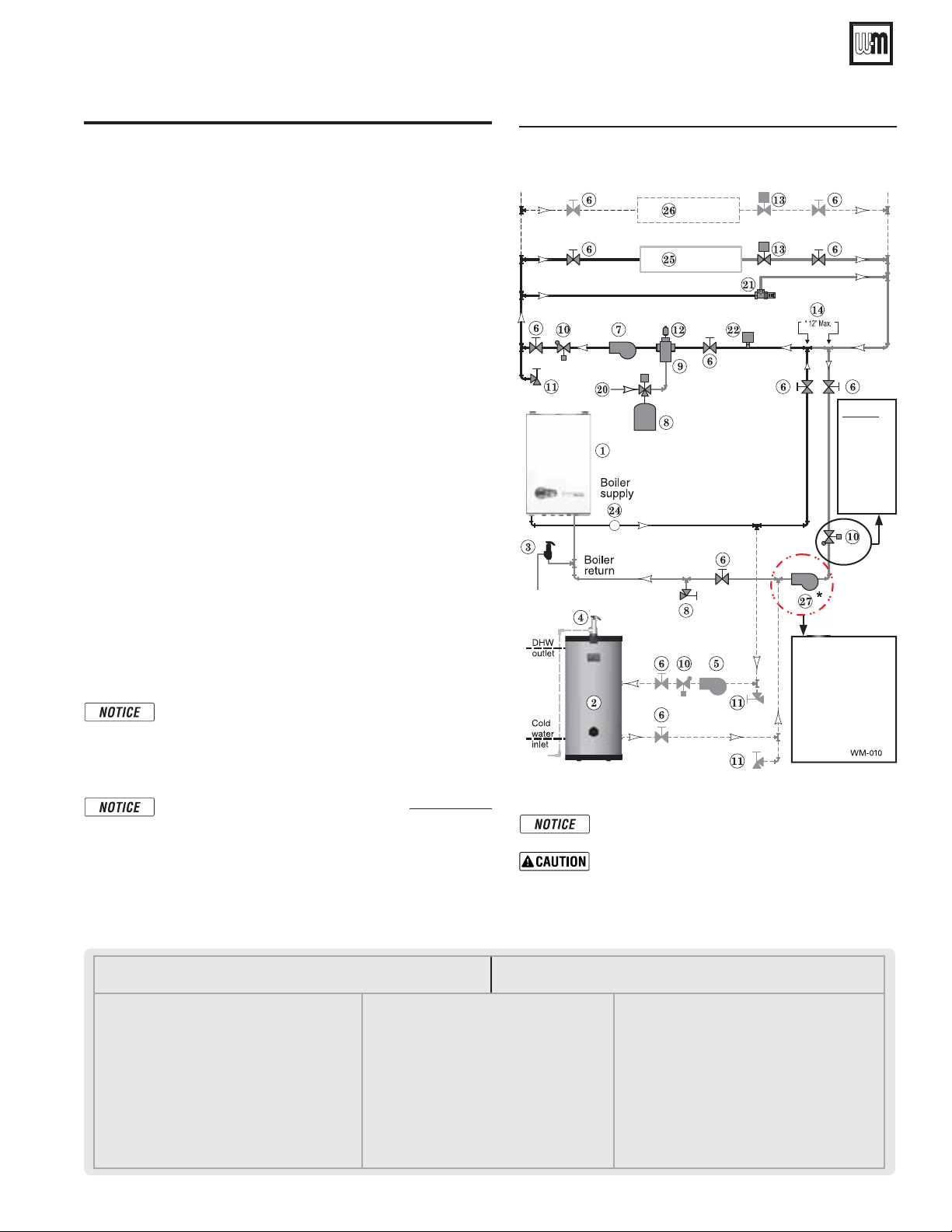
AquaBalance® SERIES 2 WALL MOUNT GAS-FIRED WATER BOILER — Boiler Manual
17 Primary/Secondary System Piping (continued)
Zone Valve zoning – primary/secondary
(Shown with optional DHW piping)
See Figure 50.
1. This configuration is for zone valve systems using a boiler
loop connected as a secondary circuit off of a primary system
loop. Systems whose flow characteristics do not comply with
those listed in Figure 47, page 36 must pipe the boiler loop as a
secondary circuit as show.
2. Systems zoned with zone valves MUST use a by-pass pressure
regulator.
3. Install a system circulator (supplied by installer) capable of
delivering the proper flow and head as shown.
Expansion Tank required
1. Provide a system expansion tank following the guidelines on
pages 35 or 37.
2. DO NOT use a closed-type tank if connecting to a boiler that
is equipped with an automatic vent.
Domestic Hot Water (DHW) tank, if used
1. DHW direct connection—Pipe from the near-boiler piping to
the DHW tank’s boiler connections as shown.
2. DHW as zone—A DHW tank can be connected as a zone if a
DHW tank is NOT already connected to the boiler. To provide
DHW priority operation, use a zone controller. See notices
on page 49 to ensure compliance with the 2007 Energy Act.
3. DHW Priority operation—The control turns off space heating
to the HEAT zones during domestic water heating calls on the
DHW input. The MAX ON TIME setting can be adjusted to
limit how long this occurs. Set the MAX ON TIME to “0” to
disable domestic priority. See page 63 for setting instructions.
4. If NOT connecting an indirect water heater, do not use the DHW
input or DHW Circulator output on the control.
Overriding the Outdoor Reset function by connecting
space heating zones to inputs and outputs intended
for DHW applications may violate Section 303 of
the 2007 Energy Act. See page 131 for compliance
information and exemptions.
Figure 50 Zone valve zoning — primary/secondary
connection — a system circulator is required
Note:
Do not
install
on
Combi
Boilers.
(See Note,
page 40)
Note: This
pump does
not run in
DHW mode
on Heating
Only Boilers.
Wiring the Indirect tank aquastat to the Heating Only
Boilers, refer to Section 21 - Field Wiring.
Controlling the Zones
1. The control can be used to control space heating only, domestic
water heating only, or both. Refer to field wiring, beginning
on page 48, for instructions on wiring to zone valves.
2. The boiler and zone valves can also be operated by a zone
controller.
LEGEND for Figure 50.
1 AquaBalance® wall mount boiler
2 Indirect Water Heater, if used
3 Relief valve, field piped — MUST be piped to boiler return
connection on Combi boilers, Heating Only boilers relief
valve field piped on supply.
4 Relief valve piping to drain — see page 38
5 DHW circulator
6 Isolation valves
7 System circulator
8 Expansion tank, diaphragm type, if used
9 Air separator
10 Flow/check valves
11 Purge/drain valves
(Installer supplied)
Part number 550-100-325/0718
12 Auto air vent
13 Zone valves
14 Primary/secondary connection (tees no more than
12 inches apart)
15 Expansion tank, closed type, if used (some chiller
systems may use a diaphragm-type expansion tank)
16 Water chiller
17 Check valve
18 Y-strainer
19 Balancing valve
20 Make-up water supply – Use applicable codes to deter
mine if backflow preventers, pressure reducing valves,
and fill valves may be required
Connect zone valve end switches to HEAT input.
Connect system circulator to HEAT Circ. output.
Use isolation relays if connecting 3-wire zone
valve end switches to the HEAT input.
Note: This is a common legend for all piping diagrams, Not all
items listed appear in every figure.
21 By-pass pressure regulator, REQUIRED for zone valve
systems unless other provision is made
22 High limit temperature control
23 Zone circulator
24 Pressure/temperature gauge,
25 Heating circuits
26 Additional heating circuits, if any
27 Boiler circulator,
Combi boiler the circulator is already inside the boiler
jacket).
28 Mixing valve, if any
*
(field supplied), field piped
(For Heating Only boilers, In the
39
Page 40
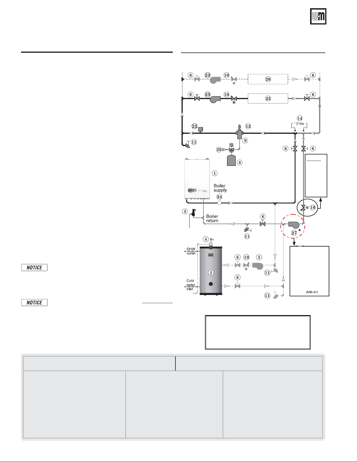
AquaBalance® SERIES 2 WALL MOUNT GAS-FIRED WATER BOILER — Boiler Manual
17 Primary/Secondary System Piping (continued)
Circulator zoning – primary/secondary
(Shown with optional DHW piping)
See Figure 51.
1. This configuration is for circulator-zoned systems using a boiler
loop connected as a secondary circuit off of a primary system
loop. Systems zoned with circulators must pipe the boiler loop
as a secondary circuit as show.
2. Install a separate circulator (supplied by installer) for each zone
capable of delivering the proper flow and head as shown.
Expansion Tank required
1. Provide a system expansion tank following the guidelines on
pages 35 or 37.
2. DO NOT use a closed-type tank if connecting to a boiler that
is equipped with an automatic vent.
Domestic Hot Water (DHW) tank, if used
1. DHW direct connection — Pipe from the near-boiler piping
to the DHW tank’s boiler connections as shown.
2. DHW as zone—A DHW tank can be connected as a zone if a
DHW tank is NOT already connected to the boiler. To provide
DHW priority operation, use a zone controller. See notices
on page 49 to ensure compliance with the 2007 Energy Act.
3. DHW Priority operation—The control turns off space heating
to the HEAT zones during domestic water heating calls on the
DHW input. The MAX ON TIME setting can be adjusted to
limit how long this occurs. Set the MAX ON TIME to “0” to
disable domestic priority. See page 63 for setting instructions.
4. If NOT connecting an indirect water heater, do not use the
DHW input or DHW Circulator output on the control.
Overriding the Outdoor Reset function by connecting
space heating zones to inputs and outputs intended
for DHW applications may violate Section 303 of
the 2007 Energy Act. See page 131 for compliance
information and exemptions.
Figure 51 Circulator zoning plus optional DHW piping
Note:
Do not
install
on
Combi
Boilers.
(See Note,
below)
Note: This
pump does
not run in
DHW mode
on Heating
Only Boilers.
Wiring the Indirect tank aquastat to the Heating Only
Boiler, refer to Section 21 - Field Wiring.
Controlling the Zones
1. The control can be used to control space heating only, domestic
water heating only, or both. Refer to field wiring, beginning
on page 48, for instructions on wiring to circulators.
2. The boiler and circulators can also be operated by a zone
controller.
LEGEND for Figure 51 and Figure 52
1 AquaBalance® wall mount boiler
2 Indirect Water Heater, if used
3
Relief valve, field piped — MUST be piped to boiler return
connection on Combi boilers, Heating Only boilers relief
valve field piped on supply.
4 Relief valve piping to drain — see page 38
5 DHW circulator
6 Isolation valves
7 System circulator
8 Expansion tank, diaphragm type, if used
9 Air separator
10 Flow/check valves
11 Purge/drain valves
(Installer supplied)
12 Auto air vent
13 Zone valves
14 Primary/secondary connection (tees no more than
12 inches apart)
15 Expansion tank, closed type, if used (some chiller
systems may use a diaphragm-type expansion tank)
16 Water chiller
17 Check valve
18 Y-strainer
19 Balancing valve
20 Make-up water supply – Use applicable codes to deter-
mine if backflow preventers, pressure reducing valves,
and fill valves may be required
40
NOTE: (Applies to Figures 50, 51 & 52)
Add boiler and tank head loss for pump
sizing.
Note: This is a common legend for all piping diagrams, not
all items listed appear in every figure.
21 By-pass pressure regulator, REQUIRED for zone valve
systems unless other provision is made
22 High limit temperature control
23 Zone circulator
24 Pressure/temperature gauge, (field supplied), field piped
25 Heating circuits
26 Additional heating circuits, if any
27 Boiler circulator,
Combi boiler the circulator is already inside the
boiler jacket).
28 Mixing valve, if any
(For Heating Only boilers, In the
*
Part number 550-100-325/0718
Page 41
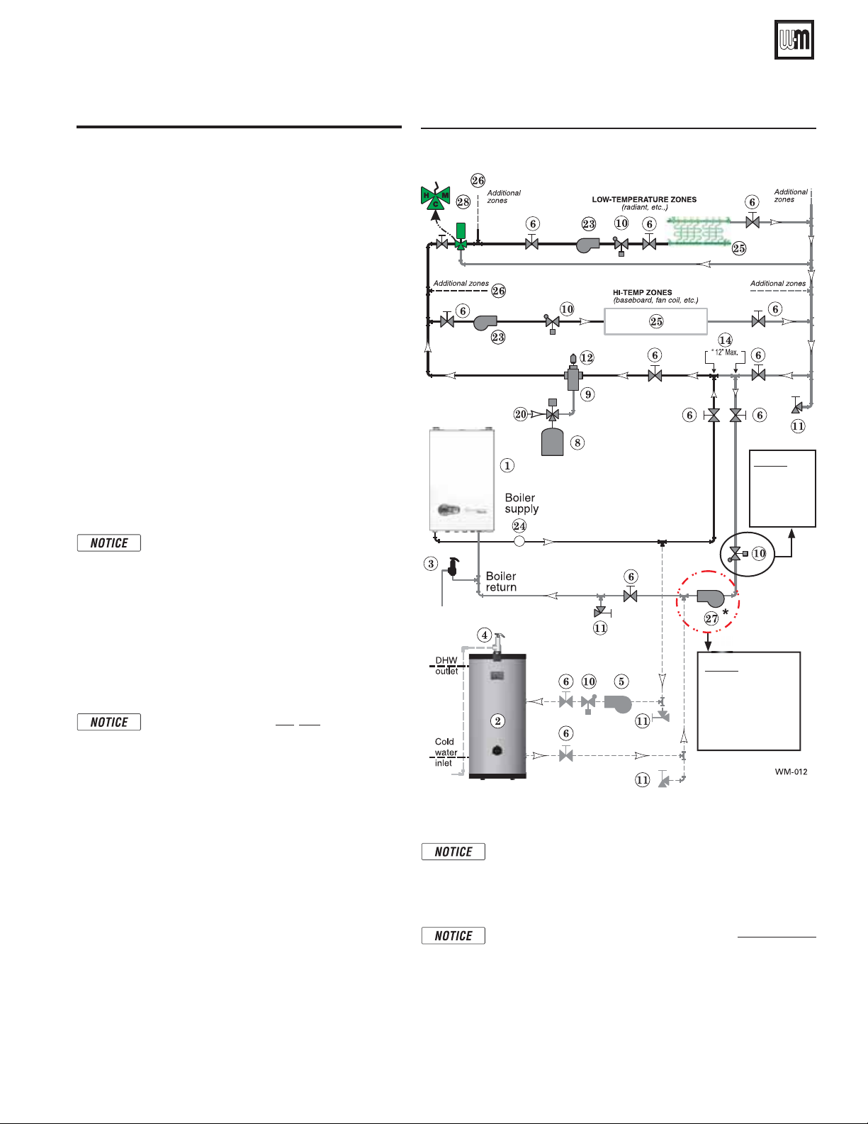
AquaBalance® SERIES 2 WALL MOUNT GAS-FIRED WATER BOILER — Boiler Manual
17 Primary/Secondary System Piping (continued)
Circulator zoning – Multiple
temperature zones with primary/
secondary
(Shown with optional DHW piping)
See Figure 52.
1. This configuration is for circulator-zoned systems with
high- and low- temperature heating zones using a
boiler loop connected as a secondary circuit off of a primary system loop. Systems zoned with circulators must
pipe the boiler loop as a secondary circuit as shown.
2. Install a separate circulator (supplied by installer) for
each zone capable of delivering the proper flow and
head as shown.
Expansion Tank required
1. Provide a system expansion tank following the guidelines on pages 35 or 37.
2. DO NOT use a closed-type tank if connecting to a boiler
that is equipped with an automatic vent.
System setup and settings
1. Hi-temp emitters may be baseboards, radiators, fan
coils, or heat exchangers.
For cast iron radiation and old black iron pip-
ing systems a “Dirt separator with a magnet”
must be installed on the return piping to
protect the boiler heat exchanger.
Figure 52 Circulator zoning with high- and low- temperature
heating zones
Note: Do
not install on
Combi
Boilers.
2. Add a mixing device (Figure 52, item 28) to help ensure
supply water temperature will not exceed the maximum
allowable for the radiant system.
3. Heating zone supply water temperature settings should
be selected for the hi-temp zones. The mixing device
regulates supply temperature to the lower-temp zones.
Boiler operation for fan coil only applica-
tions, parameter P02 ( page 95) may be set
to 20 for faster “ramp up” to boiler set point
temperature.
Domestic Hot Water (DHW) tank, if used
1. DHW direct connection—Pipe from the near-boiler
piping to the DHW tank’s boiler connections as shown.
2. DHW as zone—A DHW tank can be connected as a
zone if a DHW tank is NOT already connected to the
boiler.
To provide DHW priority operation, use a zone
controller. See notices on page 48 to ensure compliance
with the 2007 Energy Act.
3. DHW Priority operation—The control turns off space
heating to the HEAT zones during domestic water
heating calls on the DHW input. The MAX ON TIME
setting can be adjusted to limit how long this occurs. Set
the MAX ON TIME to “0” to disable domestic priority.
See page 63 for setting instructions.
4. If NOT connecting an indirect water heater, do not
use the DHW input or DHW Circulator output on the
control.
Part number 550-100-325/0718
(See Note,
page 40)
Overriding the Outdoor Reset function by connecting
Note: This
pump does
not run in
DHW mode
on Heating
Only Boilers.
space heating zones to inputs and outputs intended for
DHW applications may violate Section 303 of the 2007
Energy Act. See page 131 for compliance information and
exemptions.
Wiring the Indirect tank aquastat to the Heating Only
Boiler, refer to Section 21 - Field Wiring.
Controlling the Zones
1. The control can be used to control space heating only, domestic
water heating only, or both.
2. The boiler and circulators can also be operated by a zone controller and in some installations may be needed.
41
Page 42
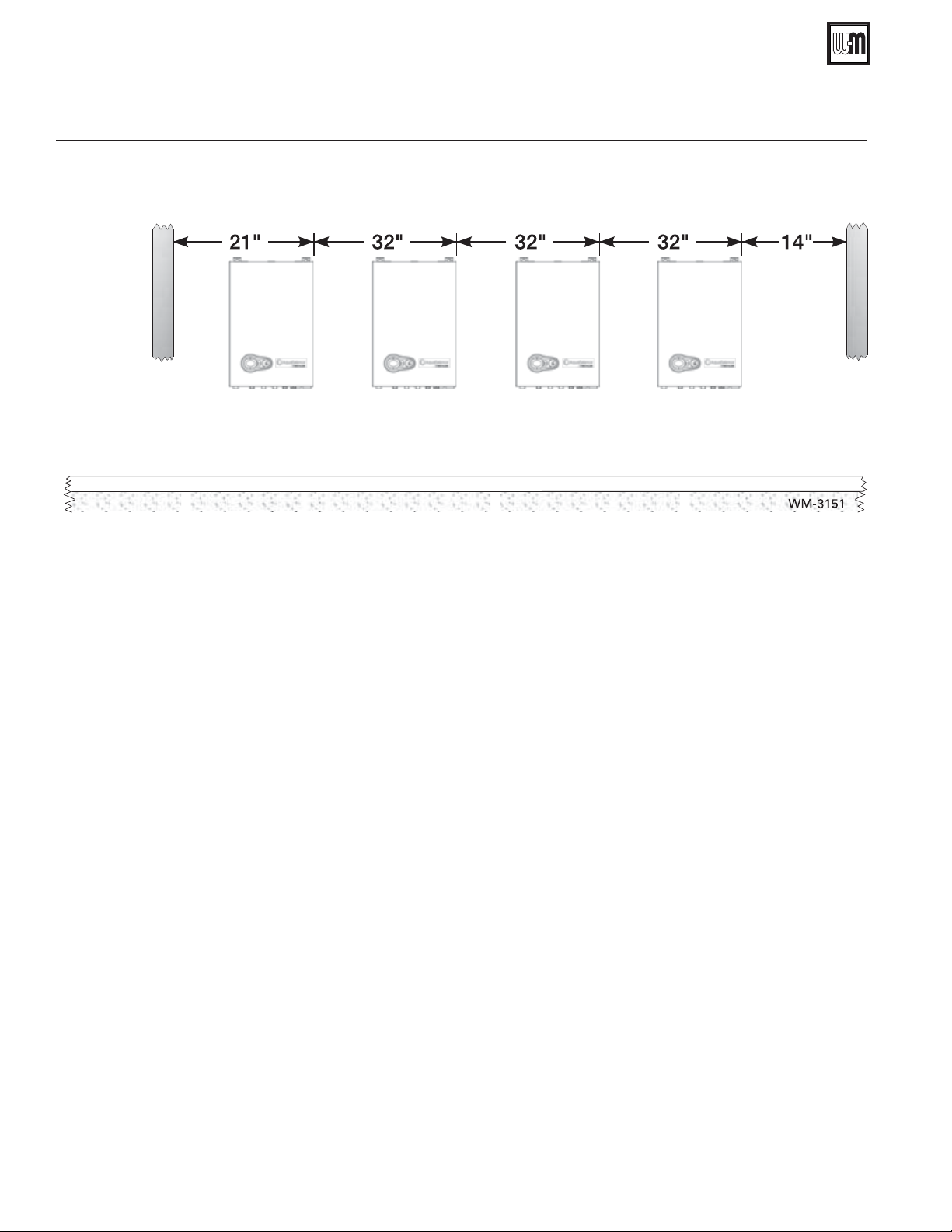
AquaBalance® SERIES 2 WALL MOUNT GAS-FIRED WATER BOILER — Boiler Manual
18 Multiple boiler installations
Figure 53 Side-to-side mounting of multiple boilers
Placing multiple boilers
1. Locate multiple boilers with spacings shown in Figure 53.
2. Provide indicated clearances around boilers for access and servicing. If recommended dimensions are not possible, provide
at least the minimum clearances given on page 5. Also follow
local codes.
3. Provide a minimum 36-inch walkway in front of the boilers to
ensure accessibility.
4. Unpack, assemble and mount boilers according to instructions
in this manual.
5. Provide clearance for installation of venting, air piping, gas piping, expansion tank, primary circulator and other accessories.
42
Part number 550-100-325/0718
Page 43
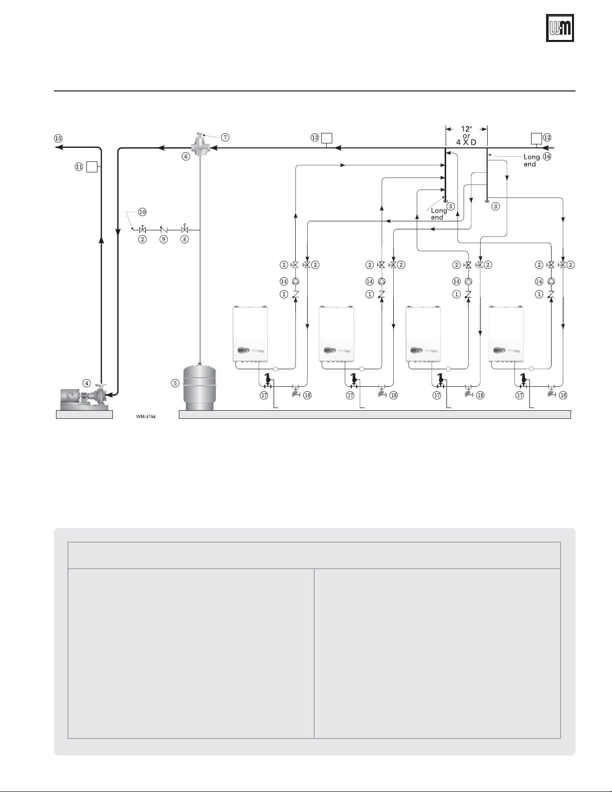
AquaBalance® SERIES 2 WALL MOUNT GAS-FIRED WATER BOILER — Boiler Manual
18 Multiple boiler installations (continued)
Figure 54 Piping schematic –– typical piping for multiple AquaBalance
®
Heating Only boilers
1 Flow/check valve
2 Isolation valves (when used)
3 Cap
4 Primary circulator
5 Expansion tank (diaphragm type)
6 System air eliminator
7 System automatic air vent
8 Pressure reducing valve
9 Check valve or backflow preventer, as required by appli-
cable codes
Part number 550-100-325/0718
Legend for Figure 54
10 Cold water supply
11 Supply water temperature control (when used)
12 Low water cutoff (when used) (place above primary
header)
13 Water flow switch (when used)
14 Boiler circulators
15 System supply
16 System return
17 Boiler P/T gauge (field supplied), relief valve and discharge
piping, installed per this manual.
18 Purge/drain valve
43
Page 44
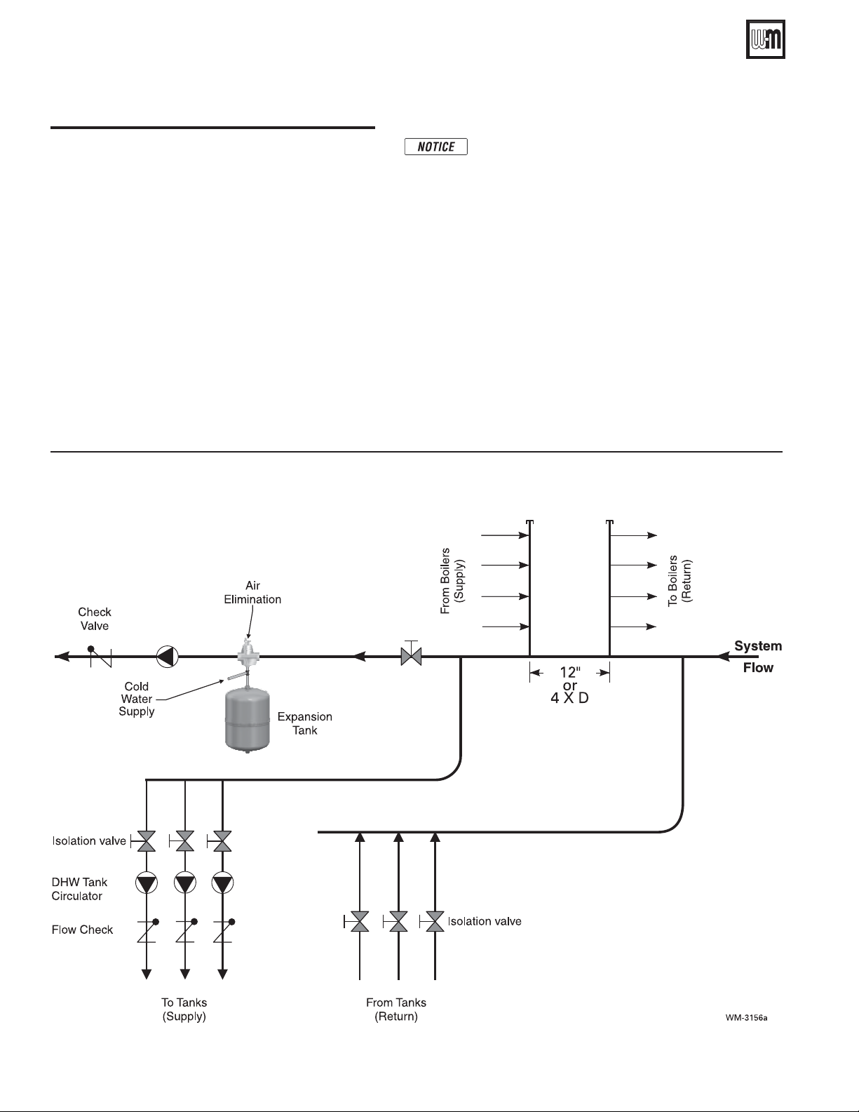
AquaBalance® SERIES 2 WALL MOUNT GAS-FIRED WATER BOILER — Boiler Manual
18 Multiple boiler installations (continued)
DHW tank piping with multiple
boilers
DHW direct connection—single tank
1. If BTUH output of a single boiler is sufficient for the
DHW tank/demand, pipe the indirect water heater to
the last boiler in the firing sequence. This will allow the
previous boilers to continue space heating while the last
boiler delivers DHW priority.
2. Pipe from the near-boiler piping to the DHW tank’s
boiler connections as shown in Figure 50, page 39.
3. Connect the DHW tank aquastat directly to the DHW
input on the last boiler in the sequence.
Figure 55 Piping layout—typical piping for multiple boilers (4-boiler system shown) with DHW storage heaters grouped as
zone in secondary loop off primary system loop. (Heating Only)
DHW tanks as zone—multiple tanks
1. If using multiple DHW tanks or multiple banks of tanks, pipe the
tanks to the primary system loop with a secondary connection as
shown in Figure 55.
2. DHW tanks are zoned with circulators as shown.
3. If DHW priority is required, use separate zone controllers for
DHW and space heating.
When using a multiple-boiler control with lead boiler
rotation, it is recommended that the boiler connected to
the DHW tank is always set as the last boiler to operate
in the sequence so that space heat can be maintained
during times of DHW demand.
44
Part number 550-100-325/0718
Page 45
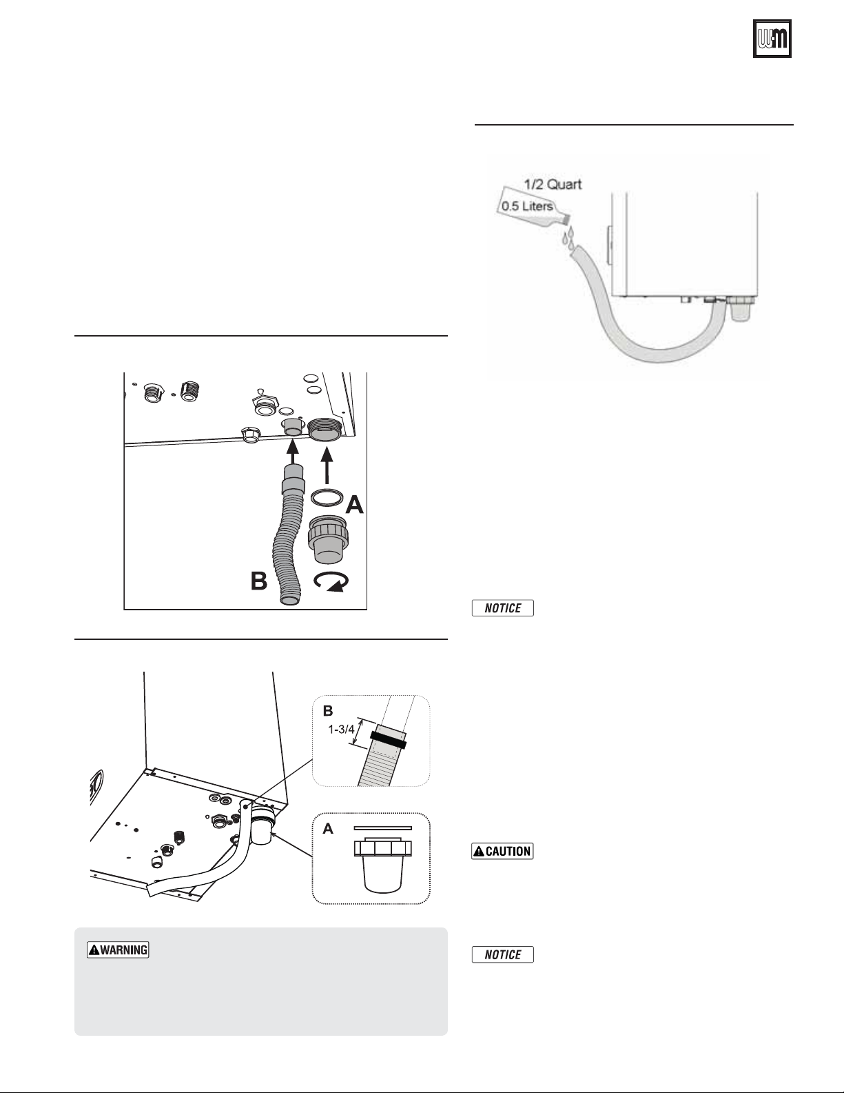
AquaBalance® SERIES 2 WALL MOUNT GAS-FIRED WATER BOILER — Boiler Manual
19 Install condensate line
Prepare condensate trap assembly
This boiler is equipped with an internal air-trap to drain off condensate.
1. Remove the condensate trap kit from the accessories bag.
2. See Figures 56, 57 and 58. The figures below shows the installation of the condensate trap connections.
3. Install the inspection coupling
tighten securely.
4. Slide the clamp (from the condensate trap kit) onto the flexible
drain tube (item
approximately 1-3/4” (Figure 57) onto the end of the tube (bottom
of boiler) as shown in Figure 56.
Figure 56 Condensate trap assembly
B), See Figure 57. Push the flexible tube (item B)
A and gasket as shown. Finger
Figure 58 Filling the condensate trap assembly
5. Fill the air-trap with approximately 1/2 quart (0.5
liters) of water and connect the condensate drain tube
to the condensate drain system
Condensate drain system
1. Install condensate drain by connecting tubing or PVC
pipe to the flexible drain line. Run the drain tubing
or piping to a floor drain or condensate pump
flexible drain line will fit in a ¾” PVC coupling. Run
minimum ½” PVC for the piping to drain or condensate
pump.
. The
Figure 57 Condensate trap connection
The condensate trap must be in place during all op-
eration. Make sure the trap is securely attached to the
condensate outlet and that the condensate discharge
line is in good condition and installed per this manual. Failure to comply could result in severe personal injury, death or substantial property damage.
Use materials approved by the authority having
jurisdiction. In the absence of other authority,
PVC and CPVC pipe must comply with ASTM
D1785, F441 or D2665. Cement and primer
must comply with ASTM D2564 or F493. For
Canada, use CSA or ULC certified PVC or
CPVC pipe, fittings and cement.
2. Select a condensate pump (if used) that is approved for
use with condensing boilers and furnaces. The pump
should have an overflow switch to prevent property
damage from condensate spillage. The pump should
have a minimum capacity of 2 GPH for the AB-80,
3 GPH for the AB-120 or 4 GPH for the AB- 155.
3. When sizing condensate pumps, make sure to include
the total load of all appliances connected to it.
The condensate line must remain unob-
structed, allowing free flow of condensate. If
condensate is allowed to freeze in the line or
if the line is obstructed in any other manor,
condensate can exit from the boiler tee, resulting in potential water damage to property.
Condensate from the boiler will be slightly
acidic (typically with a pH from 3.2 to 4.5).
Install a neutralizing filter when draining into
metal pipe and if required by local codes. See
Replacement parts section at the end of this
manual for the Weil-McLain kit.
Part number 550-100-325/0718
45
Page 46
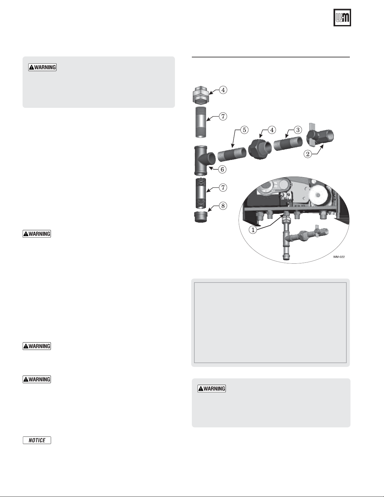
AquaBalance® SERIES 2 WALL MOUNT GAS-FIRED WATER BOILER — Boiler Manual
20 Gas piping
Boilers are shipped ready to fire natural gas
ONLY. You must install the propane venturi
if the boiler will be connected to propane.
See page 10. Failure to comply could result in
severe personal injury, death or substantial
property damage.
Connecting gas supply piping
1. Remove jacket door and refer to Figure 59 to pipe gas to
boiler.
a. Place a pipe wrench on the gas line inside the jacket
when tightening the gas line assembly to the boiler gas
connection (item 1).
b. Install steel pipe fittings as shown in Figure 59. All pipe
fittings and gas cock are supplied by the installer.
c. In Canada — The gas shut-off valve (item 2) must be
identified by the installer.
2. Use pipe dope compatible with propane gases. Apply sparingly only to male threads of pipe joints so that pipe dope
does not block gas flow.
Failure to apply pipe dope as detailed above can
result in severe personal injury, death or substantial property damage.
3. Connect gas supply piping to the ½” NPT gas cock for
80/120 boilers and ¾” NPT for 155 boilers (item 2).
4. Support gas piping with hangers, not by boiler or its accessories.
5. Purge all air from gas supply piping.
6. Before placing boiler in operation, check boiler and its gas
connection for leaks.
a. During any pressure testing at less than 13” w.c., close
the gas shutoff valve and disconnect system gas piping.
At higher test pressures, disconnect boiler and gas valve
from gas supply piping.
Do not check for gas leaks with an open flame
— use bubble test. Failure to use bubble test or
check for gas leaks can cause severe personal
injury, death or substantial property damage.
Figure 59 Connect gas supply piping
(Combi boiler shown).
1 Boiler gas supply connection, ½” NPT male for 80/120 boilers
and ¾” NPT for 155 boilers.
ALL OF THE FOLLOWING ARE SUPPLIED BY THE INSTALLER:
2 T-handle gas cock, ½” NPT for 80/120 boilers and ¾” NPT for 155 boilers.
3 Nipple, ½” NPT for 80/120 boilers and ¾” NPT for 155 boilers.
4 Unions, ½” NPT for 80/120 boilers and ¾” NPT for 155 boilers.
5 Nipple, ½” NPT for 80/120 boilers and ¾” NPT for 155 boilers.
6 Tee, ½” NPT for 80/120 boilers and ¾” NPT for 155 boilers.
7 Nippl e, ½” NPT x 6” for 80/120 boilers and ¾” NPT x 6 ” for 155 boilers,
for drip leg.
8 Cap, ½” NPT for 80/120 boilers and ¾” NPT for 155 boilers.
46
DO NOT adjust or attempt to measure gas valve
outlet pressure. The gas valve is factory-set for the
correct outlet pressure. This setting is suitable for
natural gas and propane. Attempting to alter or
measure the gas valve outlet pressure could result
in damage to the valve, causing potential severe
personal injury, death or substantial property
damage.
Flexible appliance gas connectors are NOT rec-
ommended.
Use two wrenches when tightening gas pip-
ing at boiler, using one wrench to prevent the
boiler gas line connection from turning. Failure
to support the boiler gas connection pipe to
prevent it from turning could damage gas line
components.
Part number 550-100-325/0718
Page 47
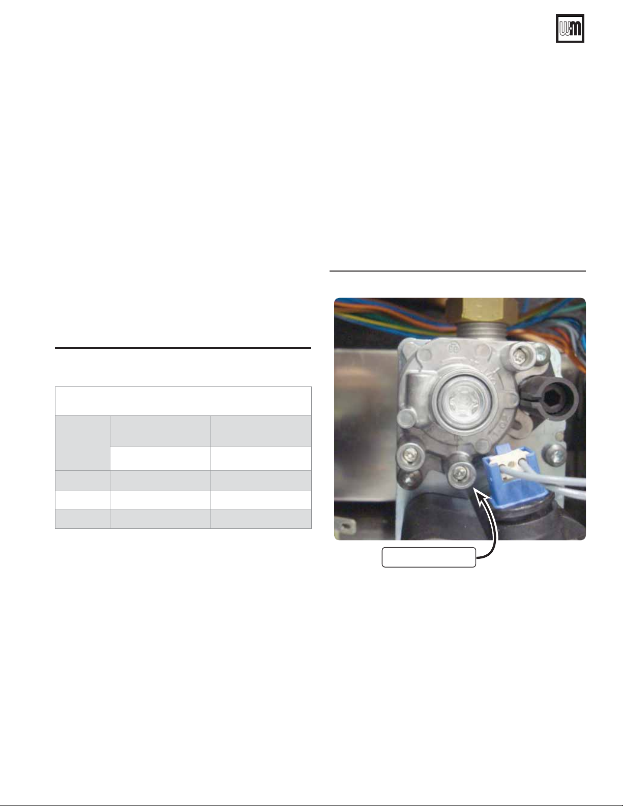
AquaBalance® SERIES 2 WALL MOUNT GAS-FIRED WATER BOILER — Boiler Manual
20 Gas piping (continued)
Gas pipe sizing
1. See page 14 for gas line sizing information.
Check gas pressure at inlet to boiler
1. See Figure 60 for location of the gas inlet pressure test port.
Check the operational (working) gas inlet
pressure
1. Set up the boiler to operate at maximum rate as described in
section “ Test mode” Figure 100, page 75.
2. With the boiler operating at maximum rate check that the operational (working) gas pressure at the inlet gas pressure test
port (see above) complies with the requirements of Table 2 .
3. Ensure that this inlet pressure can be obtained with all other
gas appliances in the property working.
Measure the gas rate
Measure the gas rate and check against following Table 2:
Table 2 Gas rate for Combi and Heating Only boilers
For natural gas or liquefied petroleum (propane) gas, the pressure required at gas valve inlet pressure port (verify minimum
gas pressure when all gas appliances are in operation):
a. Maximum: 13” w.c. with no flow (lockup) or with boiler
on.
b. Minimum: 3.5” w.c. gas pressure, with gas flowing (verify
during boiler startup, while boiler is at high fire)
c. Nominal gas pressure: 11.0” w.c.
4. Install 100% lockup gas pressure regulator in supply
line if inlet pressure can exceed 13” w.c. at any time.
Adjust lockup regulator for 13” w.c. maximum.
Figure 60 Inlet test port on gas valve
Combi
Boiler
model
AB-80
AB-120
AB-155
Gas Rate (Natural Gas)
After 10 minutes from cold
Maximum rate Minimum rate
3
/h ft3/h
ft
78.4 7.8
117.6 11.8
151.9 15.2
Inlet test port
Part number 550-100-325/0718
47
Page 48
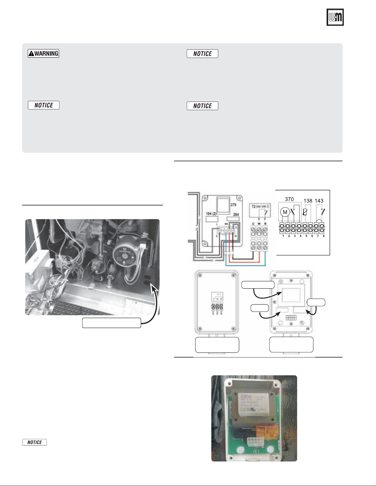
AquaBalance® SERIES 2 WALL MOUNT GAS-FIRED WATER BOILER — Boiler Manual
21 Field wiring
ELECTRICAL SHOCK HAZARD — For your
safety, turn off electrical power supply at service
entrance panel before making any electrical connections to avoid possible electric shock hazard.
Failure to do so can cause severe personal injury
or death.
The installation must comply with: National
Electrical Code and any other national, state,
provincial or local codes or regulations. In
Canada, CSA C22.1 Canadian Electrical Code
Part 1, and any local codes.
Combi and Heating Only boiler
wiring
The boiler is pre-wired and is ready to be plugged into your
electrical supply. Receptacle must be a grounded and polarized circuit. Recommend GFI outlet.
Figure 61 Thermostat or sensor wiring entrances
Wiring must be N.E.C. Class 1. If original wir-
ing as supplied with boiler must be replaced,
use only type 105 °C wire or equivalent. Boiler
must be electrically grounded as required by
National Electrical Code ANSI/NFPA 70 – latest edition
Part I, CSA C22.1, Electrical Code.
, and/or the Canadian Electrical Code
The boiler when installed, must be electri-
cally bonded to ground in accordance with the
requirements of the authority having jurisdiction
or, in the absence of such requirements, with the
National Electrical Code, ANSI/NFPA 70
– latest
edition, and/or the Canadian Electrical Code
Part I, CSA C22.1, Electrical Code.
Figure 62 Thermostat terminals Combi and Central Heating
and Outdoor sensor (Heating Only Boilers)
See illustrations in the following pages for notes and
numbers.
Wire grommets
Wire entrances
All field wiring is made through the bottom of the boiler
through two (2) black grommets shown in Figure 61.
Connecting terminals
The electrical connections terminal block can be accessed
after removing the front jacket panel. The layout of the terminals for the various connections are shown in the wiring
diagram in the following pages.
Room thermostat
When connecting a room thermostat, connect the thermostat across terminals R and W for a two (2) -wire thermostat
or optional R,W and C for a three (3) -wire thermostat, see
Figure 62, Item 72. The thermostat connector is located on
the right side of the boiler.
Either a voltage free thermostat or a 24VAC
thermostat can be connected to the boiler.
Transformer
Relay
Outside of
Thermostat-Relay
Box
Fuse
Inside of
Thermostat-Relay
Box
Figure 63 Thermostat-Relay box terminals Combi and Central
Heating boilers
48
Part number 550-100-325/0718
Page 49
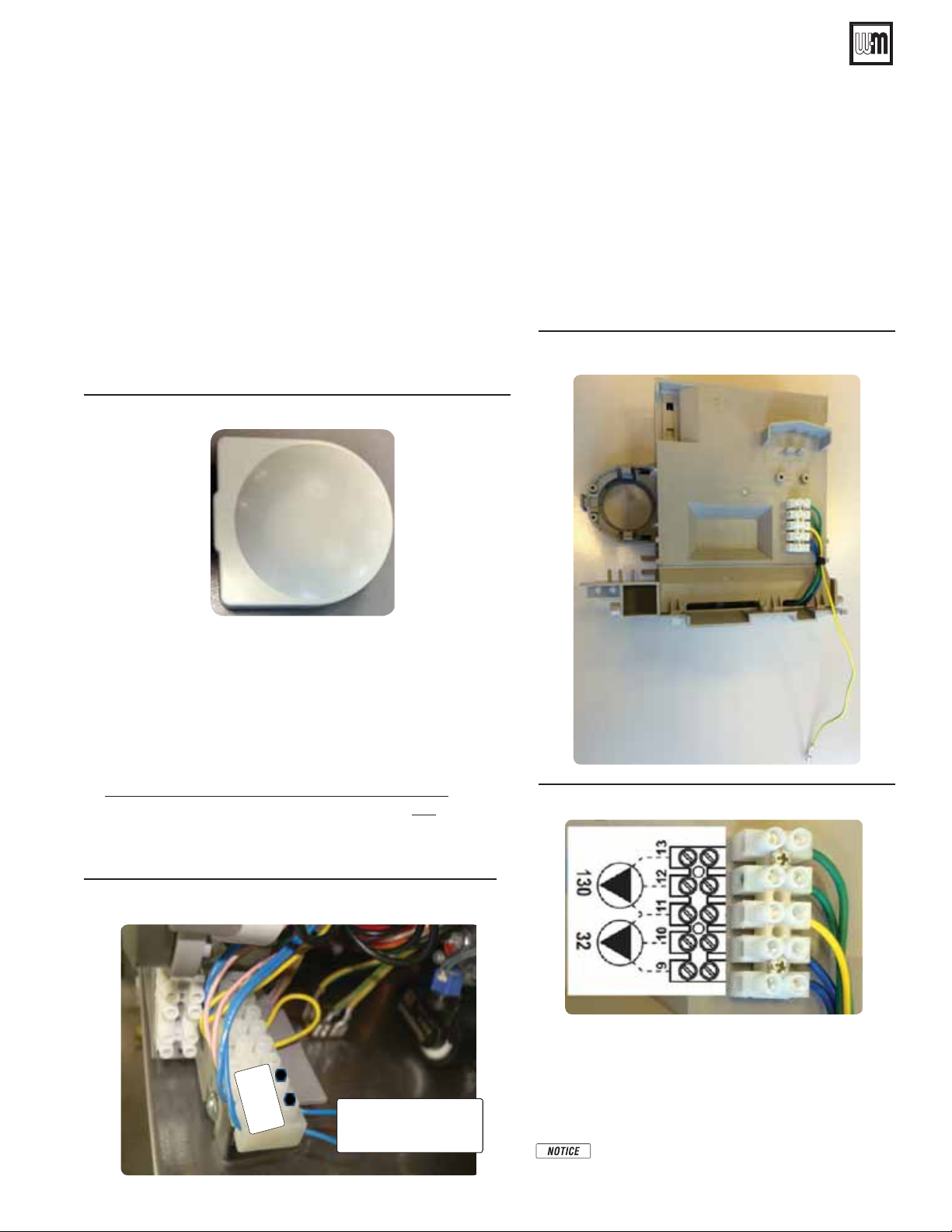
AquaBalance® SERIES 2 WALL MOUNT GAS-FIRED WATER BOILER — Boiler Manual
21 Field wiring (continued)
Outdoor temperature sensor Central Heating Boilers
(optional for Combi Boilers)
• Outdoor sensor uses the back connection block,
Item 138, (right side of block … terminals 5 and 6).
• Recommended wire size 22 AWG (2-conductor shielded thermostat wire 22 gauge).
• Mount on north exterior wall,
flow of heat or cooling from other sources, approximately 10 feet
above ground level.
• Do NOT run sensor wires with other electrical wires.
The Outdoor sensor must be installed unless specifically exempted in the Energy Act statement on page 131.
Figure 64 Outdoor sensor optional for Combi boiler.
shielded from direct sunlight or
see Figure 62,
Wiring the Circulators (Heating Only Boiler)
The control of the Heating Only model of the boiler is capable of managing two (2) separate circulators, one for the
Heating circuit and one for the Domestic Hot water circuit.
The connections are located on the rear part of the control case. In order to access the connector you will have to
unscrew the screw located on the lower right corner of the
control to enable you to rotate the control and access the
connectors. See Figure 66 and Figure 67.
Figure 66 Circulator connectors (Heating Only
boilers)
Wiring the Indirect Tank Aquastat
Wiring the indirect tank aquastat to the Heating Only Boiler, will fire the
boiler to provide heated boiler water to the indirect tanks heating coil.
• Field supplied; zone panel, with priority zone, indirect circulator,
zone valve for indirect tank.
• Connect indirect aquastat N/O contact wires to boiler connections
#7 and #8, see Figure 65 below.
• Boiler must be in the “comfort mode” (not “eco” mode) push eco/
comfort button to exit “eco” mode, display will Not show “eco”
on display when in correct mode, when using an Indirect Water
Heater Tank.
Figure 65 Indirect tank aquastat connections
7
8
Indirect tank aquastat
(N/O) wire connection
points, pins 7 and 8
Figure 67 Circulator connectors detail
In Figure 67, terminals 9, 10 and 11 (Item 32) are for connecting the Heating circuit circulator.
Terminals 11, 12, and 13 (Item 130) are for connecting the
Domestic Hot water circuit circulator.
The common terminal 11 is ground.
Only one circulator may be wired to each con-
nection point.
Part number 550-100-325/0718
49
Page 50
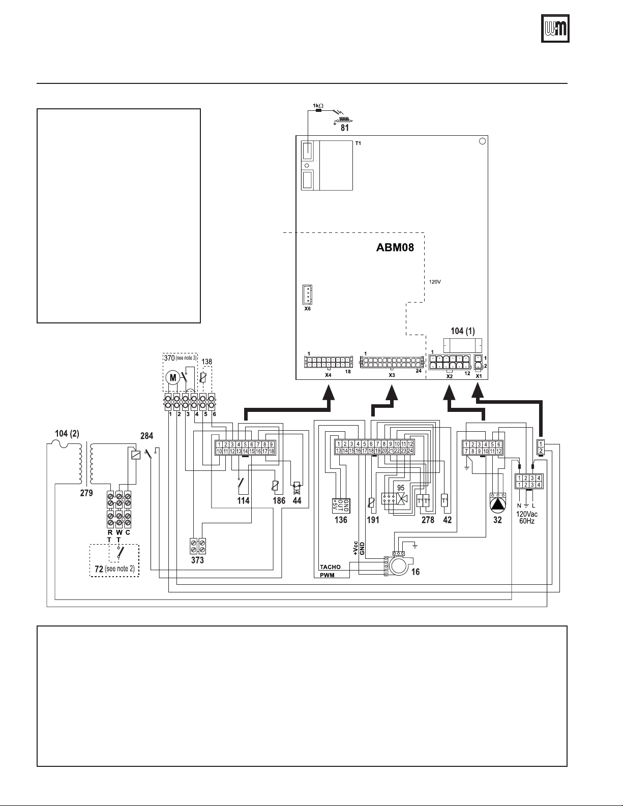
AquaBalance® SERIES 2 WALL MOUNT GAS-FIRED WATER BOILER — Boiler Manual
22 Wiring diagram — AquaBalance® 80/120C Combi Ladder
Figure 68 AquaBalance
NOTES:
1. All wiring must be installed in
accordance with N.E.C. and
any other national state or local
requirements.
2. Room thermostat should be a
dry contact type and should draw
power from the control board:
should not be greater than 24
VAC and 500 mA.
3. Terminals 1 & 2 are powered
with 120 VAC for LWCO, 3
Amps Max.
4. In case of questions during
installation please contact W-M
Tech Services.
®
80/120C –– Combi Ladder Wiring Diagram
Legend
32 Central heating pump
42 DHW temperature sensor
44 Gas valve
72 Room thermostat (not included)
81 Ignition electrode
95 Mixing (diverting) valve
104(1) Fuse 3.15A
104 (1) Fuse 630mA
50
16 Fan
cod. 3541M910
114 Water pressure switch
136 Flow meter
138 Outside temperature sensor (optional on Combi)
186 Return temperature sensor
191 Exhaust temperature sensor
278 Double sensor (heating + safety)
279 Transformer 115-24 VAC
284 Relay SPST-Coil 24 VAC
370 LWCO (not included)
373 “OPENTHERM” communication (Not used)
Part number 550-100-325/0718
Page 51
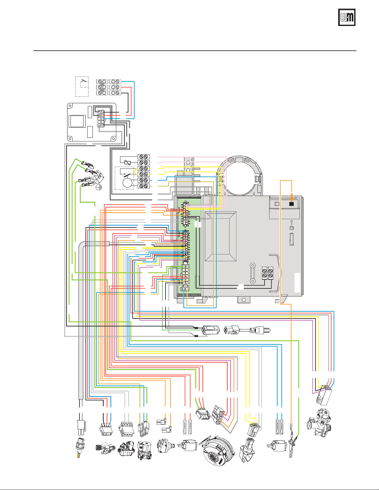
AquaBalance® SERIES 2 WALL MOUNT GAS-FIRED WATER BOILER — Boiler Manual
22 Wiring diagram — AquaBalance® 80/120C Combi Schematic
Figure 69 AquaBalance
RWC
TT
(see note 2)
72
5
284
279
X0
1
104 (2)
X0 - 1
GROUND
GROUND
GROUND
®
80/120C –– Combi Schematic Wiring Diagram
X0 - 10
X0 - 9
X0 - 8
610
X0 - 6
GROUND
X0 - 5
138
(see note 3)
370
X0 - 4
Fan
Central heating pump
D.H.W. temperature sensor
Combination gas valve
Room thermostat (not included)
Spark Electrode
.(<
X4 - 10
X4 - 2
X4 - 11
X4 - 3
X3 - 5
X3 - 1
X3 - 13
X3 - 2
X3 - 19
X3 - 7
X3 - 23
X3 - 8
X3 - 9
X3 - 24
X2 - 7
X4 - 12
X4 - 4
X4 - 13
X4 - 5
X4 - 17
X4 - 8
X3 - 18
X3 - 6
X3 - 10
X3 - 11
X1 - 2
X1 - 1
X4 - 1
X4 - 7
X3 - 12
19
1018
X4
X4 - 6
X4 - 15
1324
112
X3
M
123 456
X3 - 4
X3 - 17
X3 - 20
X3 - 21
X3 - 22
X2
X2 - 10
X2 - 4
X2 - 11
X2 - 5
104 (1)
61
12 7
X1
1
2
Diverting valve
Water pressure switch
Fuse 3.15A
Fuse 630 mA
Flowmeter
Outdoor sensor
Return temperature sensor
Exhaust temperature sensor
Double sensor (safety + heating)
Transformer 115-24 Vac
373
X4 - 6
X4 - 15
Relay SPST-Coil 24 Vac
Low Water Cutoff (not included)
“OPENTHERM” communication
ABM08
GROUND
X3 - 6
X3 - 18
191
Part number 550-100-325/0718
136
X3 - 13
X3 - 2
X3 - 1
X4 - 8
44
X4 - 17
X2 - 5
X2 - 11
GROUND
32
X2 - 1
114
X2 - 12
X4 - 13
X2 - 6
X4 - 5
186
X4 - 12
X4 - 4
GROUND
X2 - 10
16
X2 - 4
X3 - 16
X3 - 4
X3 - 5
X3 - 17
278
X3 - 7
X3 - 19
X3 - 20
X3 - 8
60Hz
120Vac
X3 - 12
X3 - 10
X3 - 11
X3 - 24
X3 - 22
X3 - 23
GROUND
X3 - 9
X3 - 21
95
42
81
FRG0
51
Page 52
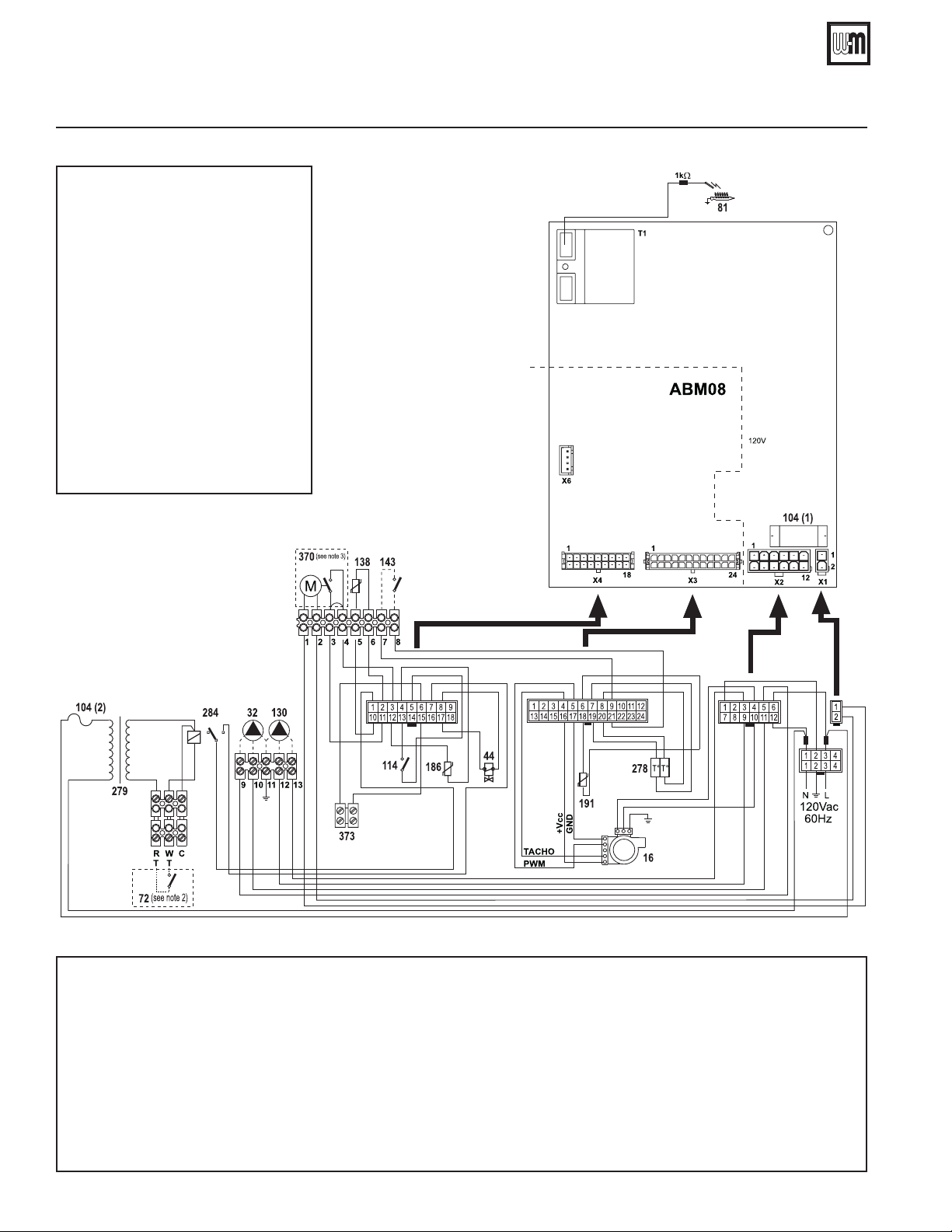
AquaBalance® SERIES 2 WALL MOUNT GAS-FIRED WATER BOILER — Boiler Manual
23 Wiring diagram — AquaBalance
Figure 70 AquaBalance
NOTES:
1. All wiring must be installed in
accordance with N.E.C. and
any other national state or local
requirements.
2. Room thermostat should be a
dry contact type and should draw
power from the control board:
should not be greater than 24
VAC and 500 mA.
3. Terminals 1 & 2 are powered with
120 VAC for LWCO. Combined
current draw for LWCO, Boiler
and DHW Pumps should not
exceed 3 Amps Max.
4. In case of questions during installation please contact W-M Tech
Services.
®
80/120H –– Heating Only Ladder Wiring Diagram
®
80/120H Heating Only Ladder
Legend
32 Central heating pump
42 DHW temperature sensor
44 Gas valve
72 Room thermostat (not included)
81 Ignition electrode
95 Mixing (diverting) valve
104(1) Fuse 3.15A
104 (1) Fuse 630mA
52
16 Fan
cod. 3541M870
114 Water pressure switch
136 Flow meter
138 Outside temperature sensor (optional on Combi)
186 Return temperature sensor
191 Exhaust temperature sensor
278 Double sensor (heating + safety)
279 Transformer 115-24 VAC
284 Relay SPST-Coil 24 VAC
370 LWCO (not included)
373 “OPENTHERM” communication (Not used)
Part number 550-100-325/0718
Page 53
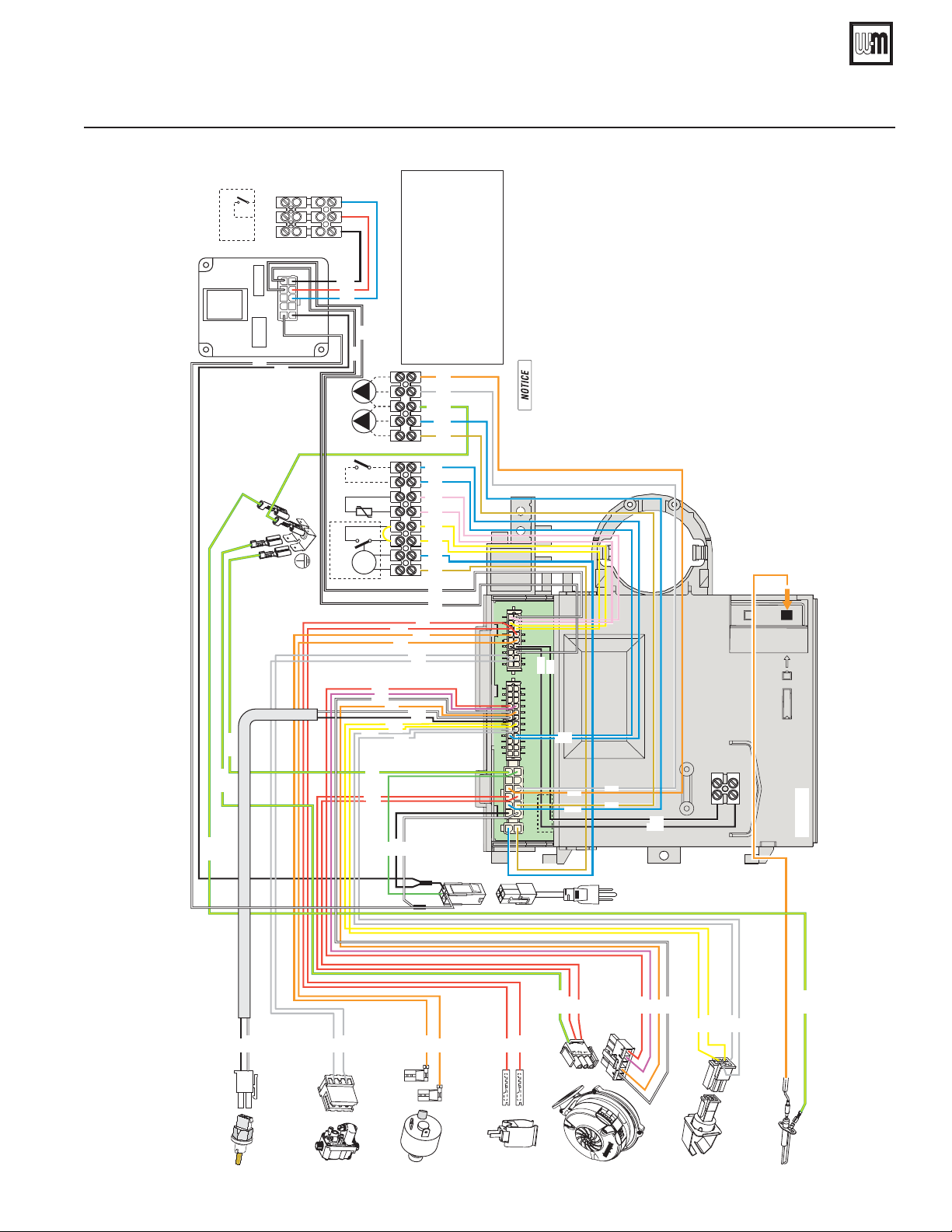
AquaBalance® SERIES 2 WALL MOUNT GAS-FIRED WATER BOILER — Boiler Manual
23 Wiring diagram — AquaBalance
(see note 2)
72
279
104 (2)
GROUND
GROUND
®
80/120H –– Heating Only Schematic Wiring Diagram
RWC
TT
5
284
X0
1M610
X0 - 1
X0 - 6
GROUND
X0 - 10
X0 - 9
X0 - 8
X0 - 4
X0 - 5
32 130
143
138
(see note 3)
370
7HUPLQDO /LQH
7HUPLQDO 1HXWUDO
7HUPLQDO /LQH
7HUPLQDO 1HXWUDO
3XPS:LULQJ&RQQHFWLRQV
X2 - 9
X2 - 3
GROUND
X2 - 11
X4 - 12
X4 - 5
X3 - 8
X2 - 6
X4 - 17
X4 - 8
X3 - 18
X3 - 6
X2 - 5
X3 - 21
X3 - 9
X4 - 10
X4 - 2
X4 - 11
X4 - 3
X1 - 2
X1 - 1
X4 - 1
X4 - 7
X4 - 4
X4 - 13
X3 - 20
X2 - 7
X2 - 10
X2 - 4
910111213123 456 78
X3 - 16
X3 - 4
X3 - 17
X2 - 1
X3 - 5
X3 - 19
X3 - 7
X2 - 12
Figure 71 AquaBalance
GROUND
®
80/120H Heating Only Schematic
each connection point. Maximum
amp load per pump 3.0 amps.
Only one circulator may be wired to
Fan
Central heating pump (not included)
Combination gas valve
Room thermostat (not included)
Spark Electrode
.(<
19
1018
X4
X4 - 6
X4 - 15
1324
112
X3
X3 - 9
X3 - 21
Water pressure switch
Fuse 3.15A
Fuse 630 mA
D.H.W. Pump (not included)
Outdoor sensor
D.H.W. tank thermostat (not included)
Return temperature sensor
Exhaust temperature sensor
Double sensor (safety + heating)
Transformer 115-24 Vac
Relay SPST-Coil 24 Vac
Low Water Cutoff (not included)
373
X2 - 3
X2 - 9
X2
61
12 7
2
104 (1)
X1
1
X2 - 5
X2 - 11
X4 - 6
X4 - 15
ABM08
“OPENTHERM” communication
X3 - 6
191
Part number 550-100-325/0718
X3 - 18
60Hz
120Vac
GROUND
X2 - 10
X2 - 4
X4 - 8
X4 - 17
44
X4 - 13
X4 - 5
114
186
X4 - 4
X4 - 12
16
X3 - 16
X3 - 4
X3 - 5
X3 - 17
278
X3 - 7
X3 - 19
X3 - 20
X3 - 8
GROUND
FRG0
81
53
Page 54
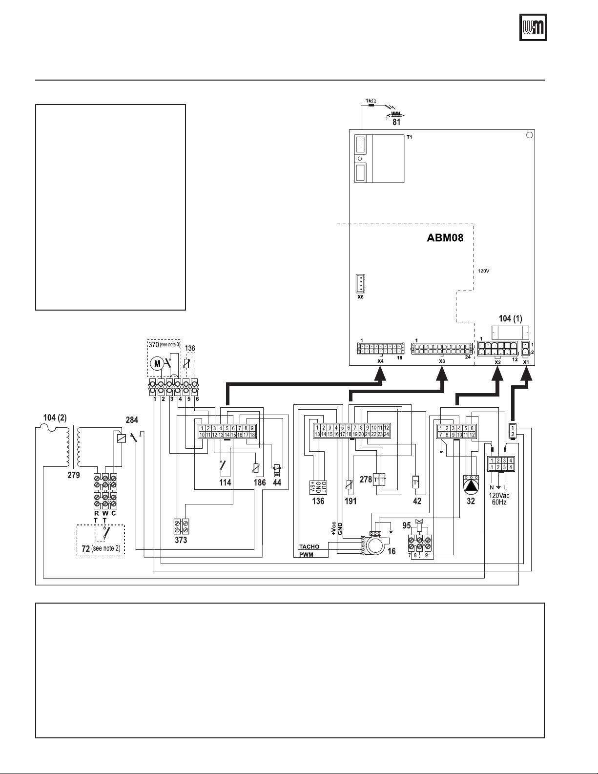
AquaBalance® SERIES 2 WALL MOUNT GAS-FIRED WATER BOILER — Boiler Manual
24 Wiring diagram — AquaBalance
Figure 72 AquaBalance
NOTES:
1. All wiring must be installed in
accordance with N.E.C. and
any other national state or local
requirements.
2. Room thermostat should be
a dry contact type and should
draw power from the control
board: should not be greater
than 24 VAC and 500 mA.
3. Terminals 1 & 2 are powered
with 120 VAC for LWCO, 3
Amps Max.
4. In case of questions during
installation please contact W-M
Tech Services.
®
155C –– Combi Ladder Wiring Diagram
®
-155C Combi Ladder
Legend
32 Central heating pump
42 DHW temperature sensor
44 Gas valve
72 Room thermostat (not included)
81 Ignition electrode
95 Mixing (diverting) valve
104(1) Fuse 3.15A
104 (2) Fuse 630mA
54
16 Blower
114 Water pressure switch
136 Flow meter
138 Outside temperature sensor (optional on Combi)
186 Return temperature sensor
191 Exhaust temperature sensor
278 Double sensor (heating + safety)
279 Transformer 115-24 VAC
284 Relay SPST-Coil 24 VAC
370 LWCO (not included)
373 “OPENTHERM” communication (Not used)
Part number 550-100-325/0718
Page 55
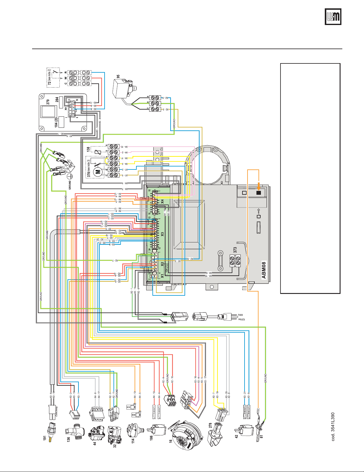
AquaBalance® SERIES 2 WALL MOUNT GAS-FIRED WATER BOILER — Boiler Manual
24 Wiring diagram — AquaBalance®-155C Combi Schematic
Figure 73 AquaBalance
®
155C –– Combi Schematic Wiring Diagram
136 Flow meter
138 Outside temperature sensor (optional on Combi)
186 Return temperature sensor
191 Exhaust temperature sensor
278 Double sensor (heating + safety)
373 “OPENTHERM” communication (Not used)
279 Transformer 115-24 Vac
284 Relay SPST-Coil 24 Vac
370 Low Water Cutoff (not included)
16 Blower
32 Central heating pump
42 DHW temperature sensor
44 Gas valve
72 Room thermostat (optional)
Legend
81 Ignition electrode
95 Mixing (diverting) valve
104 (1) Fuse 3.15A
104 (2) Fuse 630mA
114 Water pressure switch
Part number 550-100-325/0718
55
Page 56
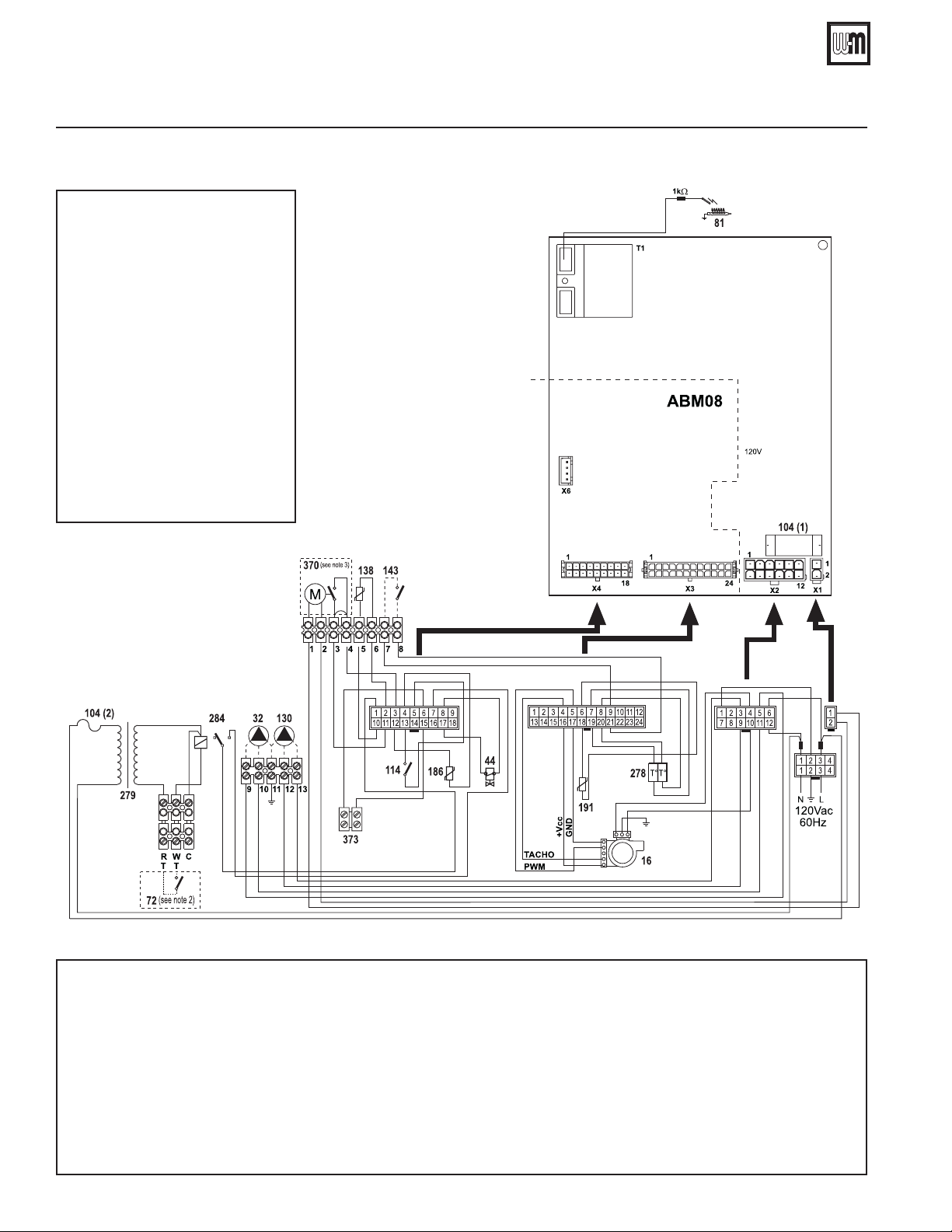
AquaBalance® SERIES 2 WALL MOUNT GAS-FIRED WATER BOILER — Boiler Manual
25 Wiring diagram — AquaBalance
Figure 74 AquaBalance
NOTES:
1. All wiring must be installed in
accordance with N.E.C. and
any other national state or local
requirements.
2. Room thermostat should be
a dry contact type and should
draw power from the control
board: should not be greater
than 24 VAC and 500 mA.
3. Terminals 1 & 2 are powered
with 120 VAC for LWCO. Combined current draw for LWCO,
Boiler and DHW Pumps should
not exceed 3 Amps Max.
4. In case of questions during
installation please contact W-M
Tech Services.
®
155H –– Heating Only Ladder Wiring Diagram
®
-155H Heating Only Ladder
Legend
32 Central heating pump (not included)
44 Combination gas valve
72 Room thermostat (not included)
81 Ignition electrode
104(1) Fuse 3.15A
104(1) Fuse 630mA
114 Water pressure switch
130 DHW pump (not included)
56
16 Fan
cod. 3541M950
138 Outdoor sensor
143 DHW tank thermostat (not included)
186 Return temperature sensor
191 Exhaust temperature sensor
278 Double sensor (heating + safety)
279 Transformer 115-24 VAC
284 Relay SPST-Coil 24 VAC
370 LWCO (not included)
373 “OPENTHERM” communication (Not used)
Part number 550-100-325/0718
Page 57
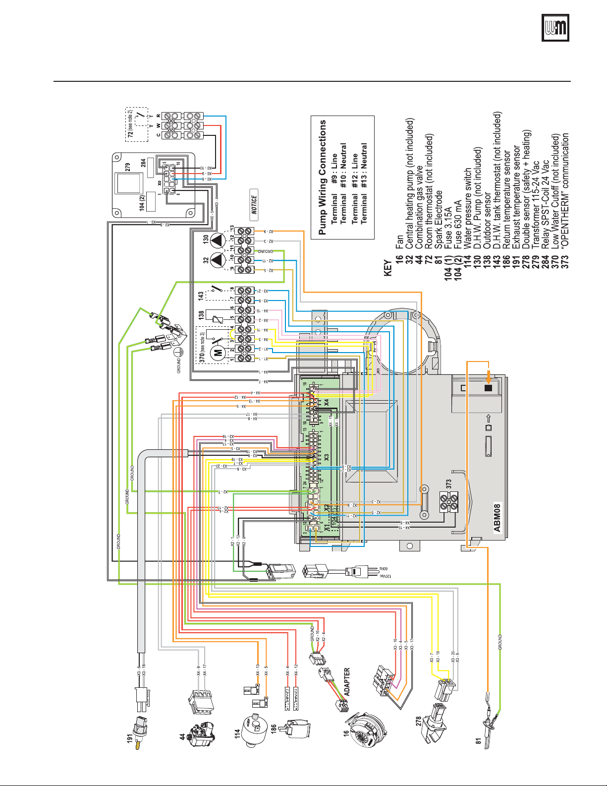
AquaBalance® SERIES 2 WALL MOUNT GAS-FIRED WATER BOILER — Boiler Manual
25 Wiring diagram — AquaBalance
Figure 75 AquaBalance
®
155H –– Heating Only Schematic Wiring Diagram
tor may be wired to
each connection point.
Maximum amp load
Only one circula-
per pump 3.0 amps.
®
-155H Heating Only Schematic
Part number 550-100-325/0718
cod. 3541M930
57
Page 58
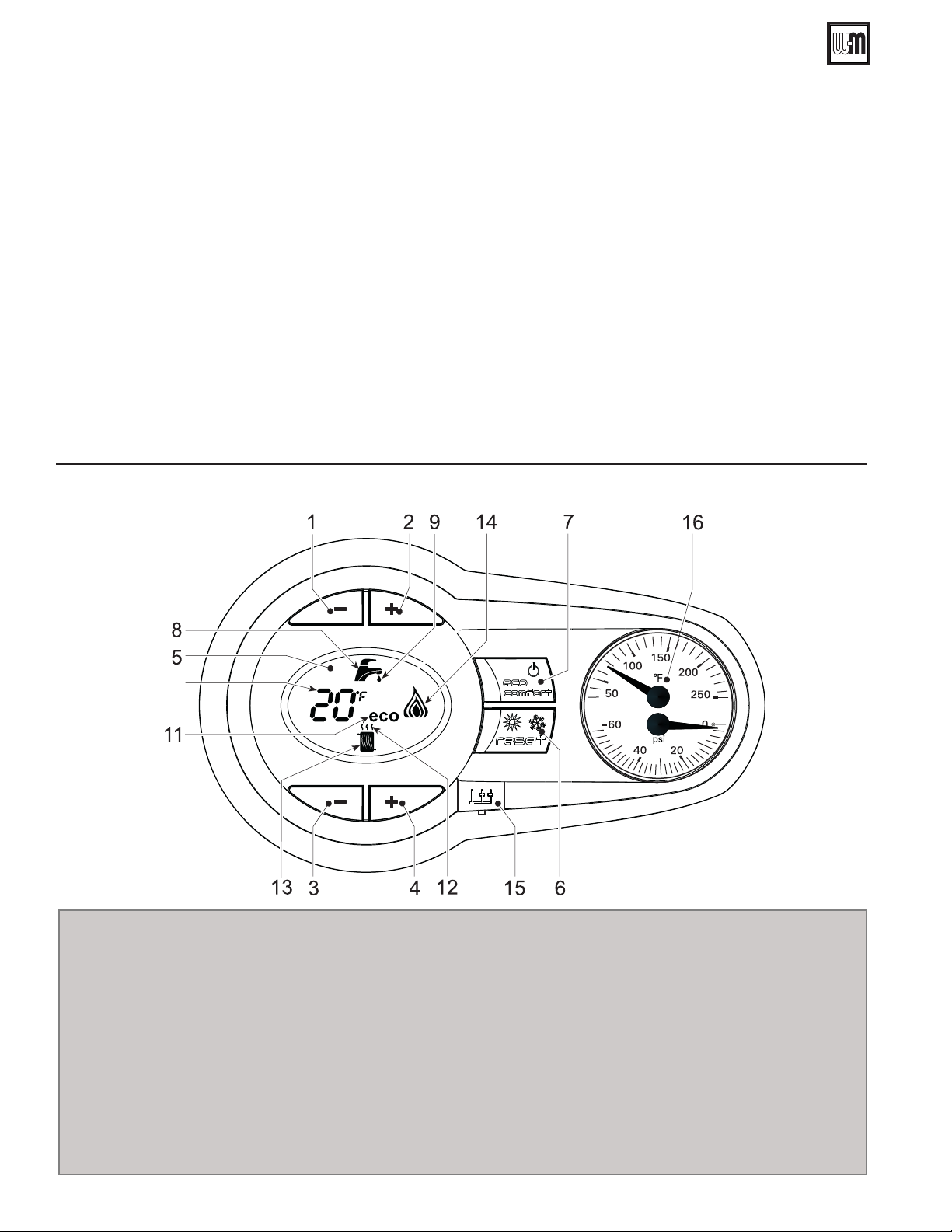
AquaBalance® SERIES 2 WALL MOUNT GAS-FIRED WATER BOILER — Boiler Manual
26 Controls and operation
Control Introduction
This boiler is a high-efficiency condensing pre-mix appliance
for central heating and hot water production, running on
Natural gas or Liquefied Petroleum (Propane) gas, generating
extremely low emissions.
The boiler is constructed with a stainless steel heat exchanger
providing effective condensation of the water vapor contained
in the flue gases, permitting extremely high efficiency.
Inside the boiler there is a premix burner with a large stainless
steel surface.
The boiler is sealed from the installation room: the air needed
for combustion is drawn from outside. The boiler also includes a
gas valve, pump, safety valve, flow sensor, dual safety and control
temperature sensor, a safety thermostat and a low water pressure
switch.
Figure 76 Control panel
Thanks to the microprocessor control and adjustment system
with advanced self-diagnosis, unit operation is for the most part
automatic. The system heating temperature is automatically
governed by the control system.
The display continuously provides information on the unit’s
operating status and it is easily possible to obtain and adjust
temperature set-points, etc. or configure them. Any operating
problems associated with the boiler are immediately signalled by
the display and, if possible, corrected automatically.
10
LEGEND for Figure 76
1 — Domestic Hot Water temperature setpoint decreasing
button
2 — Domestic Hot Water temperature setpoint increasing
button
3 — Central Heating Water temperature setpoint decreas-
ing button
4 — Central Heating Water temperature setpoint increasing
button
5 — LCD Display
6 — Reset / OTC button
7 — Economy-Comfort On-Off -Power button
8 — Domestic Hot Water symbol
9 — Domestic Hot Water mode operation
10 — Multi-function indication (Flashing during heat
exchanger protection)
11 — Economy symbol
12 — Central Heating mode operation
13 — Central Heating symbol
14 — Burner on and actual load indication
(Flashing during flame current supervision)
15 — Service tool connection
16 — Temperature-Pressure gauge
58
Part number 550-100-325/0718
Page 59
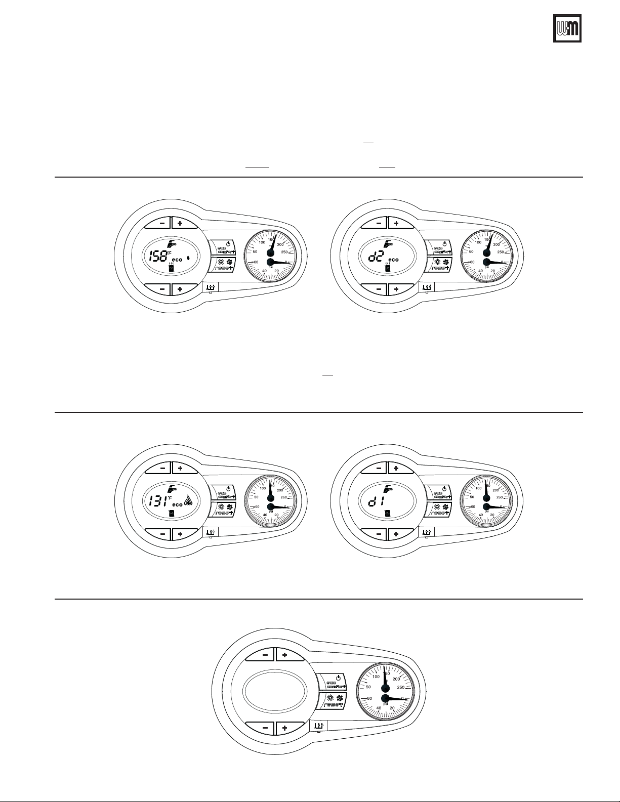
AquaBalance® SERIES 2 WALL MOUNT GAS-FIRED WATER BOILER — Boiler Manual
26 Controls and operation (continued)
Central heating operation
The Central Heating heat demand (generated by the Room Thermostat) is indicated by the flashing of the Hot Air symbol over
the radiator (Items 12 and 13 - Figure 76, page 58). The display indicates the actual Central Heating water temperature (Item 10 -
Figure 76, page 58) and when the required set point temperature is reached “d2” will be displayed.
NOTE: Heating Only boilers must be in “eco mode’. (with NO Indirect Water Heater Tank)
Figure 77 Central heating mode
Domestic hot water operation
The Domestic Hot Water heat demand (generated by the DHW flow sensor) is indicated by the flashing of the Hot Water symbol
under the tap (Items 8 and 9, Figure 76, page 58). The display indicates the actual Domestic Hot Water temperature (Item 10,
Figure 76, page 58 and after Hot set point temperature is reached “d1” will be displayed.
NOTE: Combi boilers recommended to be in “comfort” mode.
Figure 78 Domestic hot water (DHW) mode
Boiler without Power
Figure 79 Boiler without main power supply
Part number 550-100-325/0718
59
Page 60
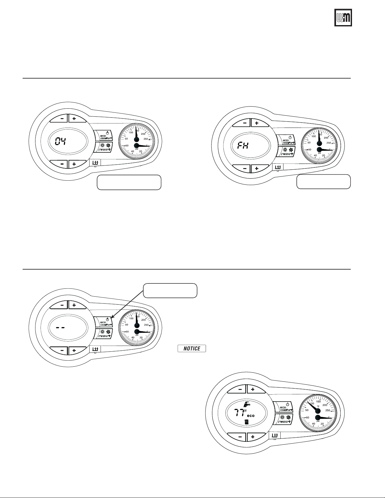
AquaBalance® SERIES 2 WALL MOUNT GAS-FIRED WATER BOILER — Boiler Manual
26 Controls and operation (continued)
Initial power up mode
Ensure the power is on to the boiler
Figure 80 Initial power up mode
Software version
During the first 5 seconds, the display shows the software version of the control module.
For the first 300 seconds, the display shows FH that identifies the Air purge function.
When the FH disappears, the boiler is ready to function automatically whenever the external controls are calling for heat.
Air purge
Power down mode
Press the on/off button (Item 7 - Figure 76, page 58) for 5 seconds.
Figure 81 Power down mode
On/Off button
When the boiler is turned off with “eco”/power button, the control
module is still powered, heating operation is disabled and the display
is off, however the frost protection will still be active.
To totally isolate, close the gas cock before the
boiler and disconnect electricity supply.
60
To turn boiler on again, press the on/off button
(Item 7 - Figure 76, page 58) hold for 5 seconds
The boiler is ready to function automatically whenever the external controls are calling for heat.
Part number 550-100-325/0718
Page 61
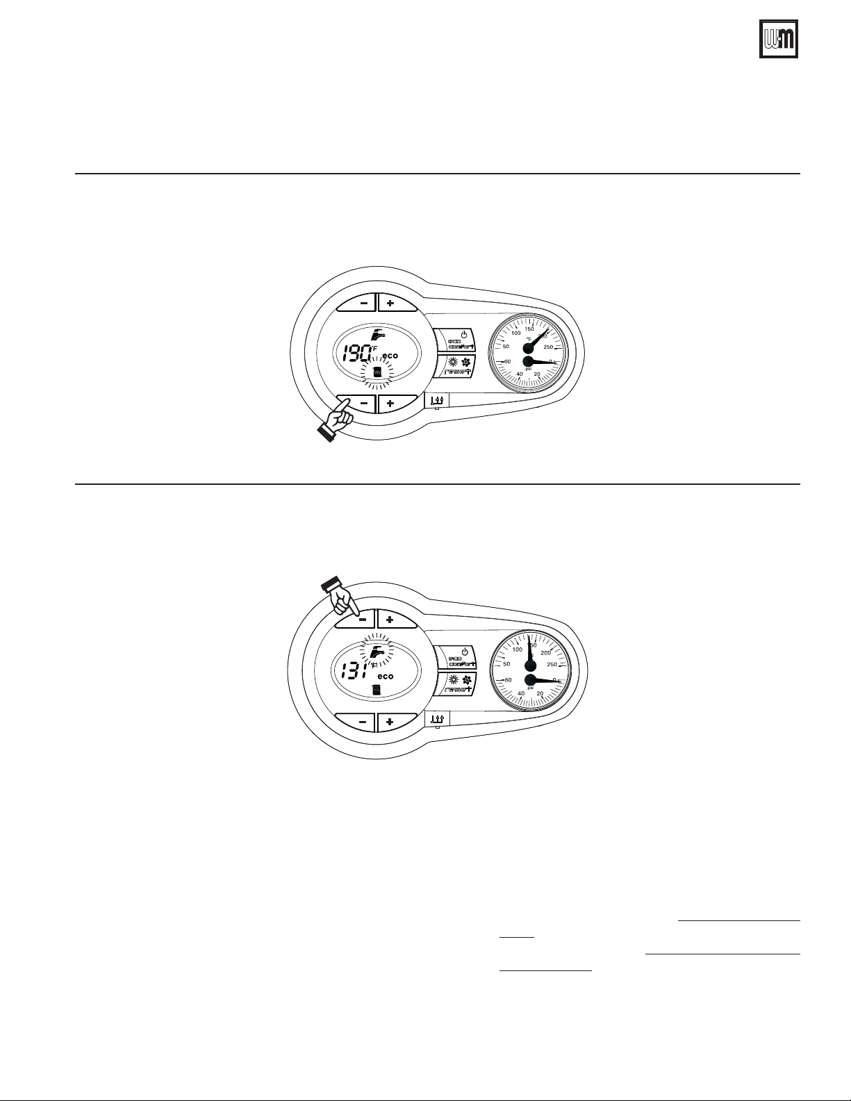
AquaBalance® SERIES 2 WALL MOUNT GAS-FIRED WATER BOILER — Boiler Manual
26 Controls and operation (continued)
Adjustments
Figure 82 Heating temperature settings
To set the system Heating temperature, use the CH buttons, “-” to reduce water setpoint “+” to increase water setpoint (Items 3
and 4 - Figure 76, page 58). It can be set from a minimum of 68° F to a maximum of 190° F.
Figure 83 Domestic hot water temperature settings
To set the Domestic hot water temperature, use the DHW buttons, “-” to reduce water setpoint “+” to increase water setpoint
(Items 1 and 2 - Figure 76, page 58). It can be set from a minimum of 104° F to a maximum of 131° F.
Room temperature adjustment (using a
room thermostat
1. Using the room thermostat, set the temperature desired.
Controlled by the room thermostat, the boiler heats the system
water to the system delivery setpoint temperature. The boiler
shuts down when the desired temperature in the room is reached.
Economy/Comfort selection
1. The unit is equipped with a special internal device that ensures a
high hot-water delivery speed and excellent user comfort. When
comfort mode is active the water in the boiler is maintained at
a pre-determined temperature, which means that hot water is
available at the boiler outlet as soon as a tap is opened, i.e. with
no waiting.
2. The user can turn the device off (“eco” mode, is a “cold
start” boiler) by pressing economy/comfort button
(Item 7 - Figure 76, page 58).
3. In “eco” mode the display shows the relevant symbol
(Item 12 - Figure 76, page 58). To turn on “comfort”
mode, press economy/comfort button (Item 7 -
Figure 76, page 58), again, the “eco” symbol will vanish
from the display.
4. Heating Only boilers must use “eco” mode.
5. Heating Only boilers with Indirect Water Heater Tank,
“eco” mode must be off.
Part number 550-100-325/0718
61
Page 62
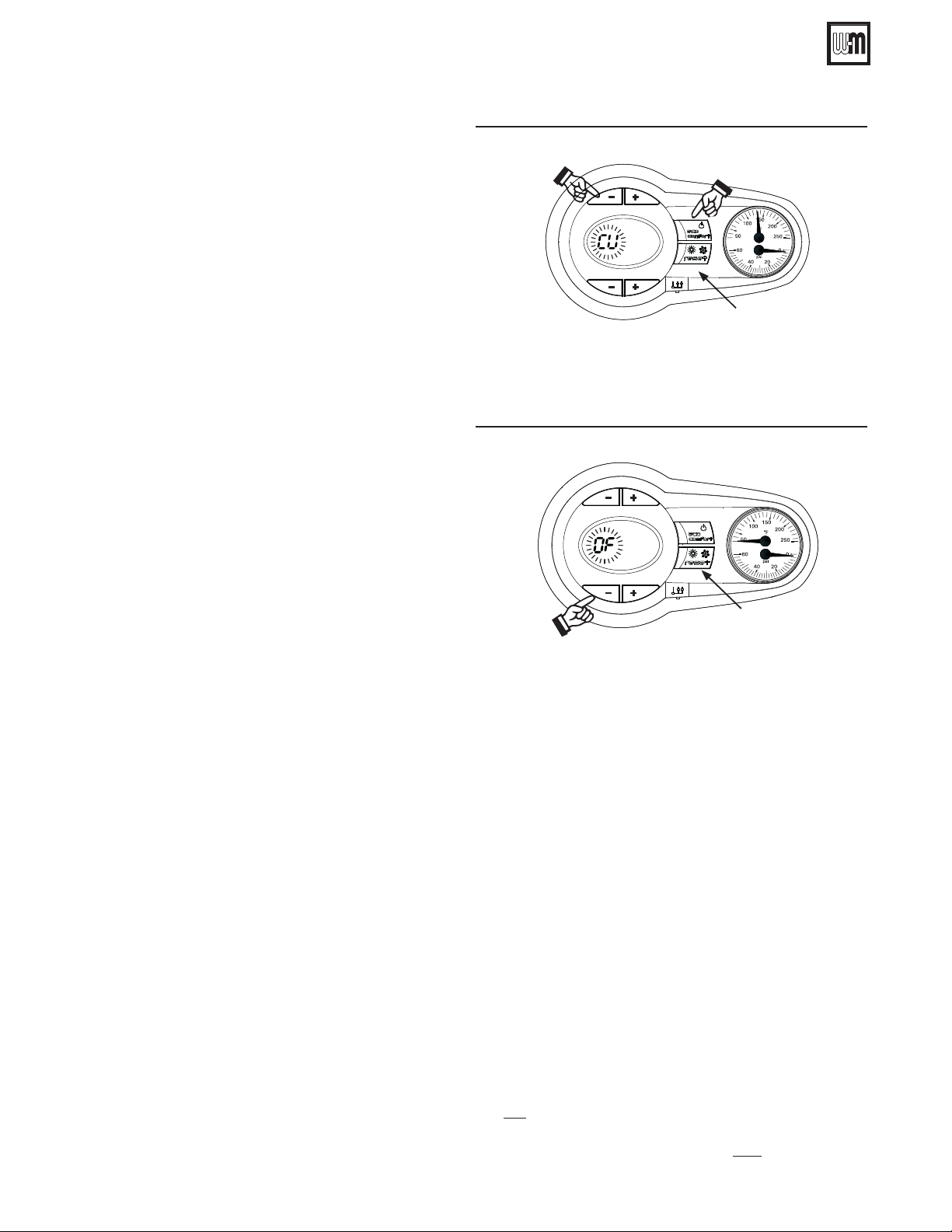
AquaBalance® SERIES 2 WALL MOUNT GAS-FIRED WATER BOILER — Boiler Manual
26 Controls and operation (continued)
Adjustments for - Heating Only Boilers
with Outdoor sensor
Optional for Combi with Outdoor sensor
Theory of Outdoor Reset Control
One of the key points to boiler efficiency, is to match the
heat generated by the boiler to the heat loss of the building
to be able to obtain a given comfort level in the living space.
• You can obtain this efficiency by selecting a scale within an
operating programmed range of the boiler water temperature. These scale ranges are related to the outdoor temperatures, and boiler water temperatures for the installed radiation.
• These “Outdoor Reset Control” curves are graphed (and programmed into the control board) by outside temperature from
68 degrees to -4 degrees F and boiler water target temperatures from 86 to 194 degrees F (see Figure 86, page 63), where
the heat loss of the home, will match the gradual increase in
boiler water temperature as the outside temperature drops.
• The average heat loss of a home may meet the needs (boiler water temperatures) of offset curve number 6 (Figure 88, page 63)
to meet the heat loss at given outdoor temperatures.
• Another example would be a high heat loss structure, where
curve number 10 would drive up the boiler water temperature
with a slight drop in outdoor temperature. (from 68 degrees
F outside temperature to just a drop to 50 degrees F outdoor
temperature, see Figure 88, page 63).
• An example of a structure with very little heat loss, (such as
a super insulated, high efficiency building) would be curve
number 1, where the outdoor temperatures continue to drop,
and the boiler water temperatures are in the low range from 86
degrees to 104 degrees F.
Outdoor Reset Control (optional on the Combi)
1. When the external outdoor sensor is attached to the boiler,
the system can work in Outside Temperature Compensation
mode. In OTC mode the temperature of the heating system
is controlled according to the external climate conditions,
this will insure a high degree of comfort and energy saving
all year round.
2. By using the CH buttons (Items 3 and 4 - Figure 84) it is pos-
sible to set the maximum system water flow temperature for
the installation.
OTC setting - with Outdoor sensor
1. To enter the OTC - reset mode, press “reset” button for 5
seconds, takes you to Curve menu.
2. The display shows “CU” flashing Figure 84; to set Curve, use
the DHW buttons (Items 1 and 2 - Figure 84) pushing CH +
or - buttons switches your screens between CU (Curves) or
OF (Offset). Display “CU” allows Curves value adjustment,
value can be varied from 1 to 10, in accordance with the
charts on page 63. “O” means no OTC mode.
3. By pressing the CH push buttons (Items 3 and 4 - Figure 84,
the display shows “0F” flashing Figure 85; to set Offset, use
the DHW push buttons (Items 1 and 2 - Figure 84).
Figure 84 OTC settings
DHW
4. It can be 68 to 104, in accordance with the chart Figure 87
or Figure 88, page 63.
5. To exit the OTC mode, press OTC button “reset” button for
5 seconds.
Figure 85 OTC “OFFSET” settings
1
2
3
4
CH
eco
OTC/reset
OTC/RESET
In the case of an outdoor sensor failure, the control
will continue to operate the boiler, but without the use of
the Compensation Curves, and an error message will flash
on the display (Fault 39 -please see Figure 118, page 93).
Upon replacement of the defective sensor the boiler will resume the use of Compensation Curves
.
OTC Exempt mode
By pressing the DHW+ and eco buttons together for 10 seconds, it is possible to enter the OTC Exempt menu. The display
starts showing the value of the parameter OTC Exempt (See
parameter Number 163, page 105) flashing. By means of the
CH - push button it is possible to change value.
(Selecting 0 - allows you to Select the Compensation curve for
your individual home heating needs). By pressing DHW+ and
eco buttons together for 10 seconds, it is possible to leave the
OTC Exempt Menu. If no action has been taken, the control
automatically leaves this mode after 2 minutes.
- 0 = installation non exempt from outside sensor connection;
- 1 = installation exempt for outside sensor connection;
Compensation curves
Curve numbers below refer to Figures 86, 87, & 88, page 63.
• Curve number 1 is for a high efficiency home with very
low heat losses. (Least aggressive curve).
• Curve number 6 is for an average home heat losses.
• Curve number 10 is for a home with high heat losses.
(Most aggressive curve).
62
Part number 550-100-325/0718
Page 63
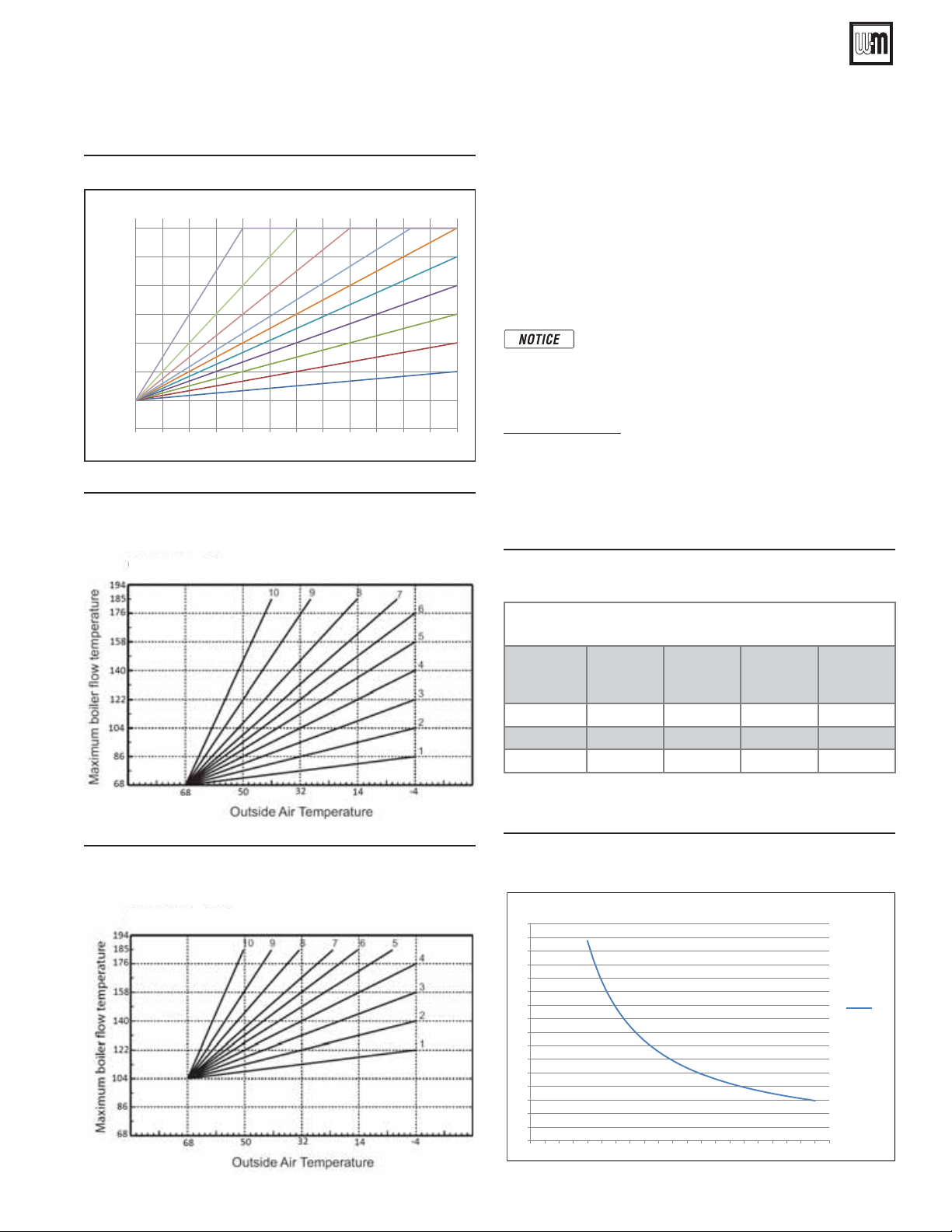
AquaBalance® SERIES 2 WALL MOUNT GAS-FIRED WATER BOILER — Boiler Manual
26 Controls and operation
Adjustments for Heating Only Boilers
with Outdoor sensor
Figure 86 Compensation curves
OTC CURVES
194
176
158
140
122
104
86
BOILER FLOW TEMPERATURE (°F)
68
OUTSIDE AIR TEMPERATURE (°F)
Figure 87 Compensation parallel offset curves
Typical low temperature radiant application
such as in-floor tubing.
2))6(7
78910
-42814202632384450566268
27 DHW Settings (Combi Only)
Boiler must be set on comfort mode
DHW SETTINGS
1. The DHW SETTINGS menus are for setting control operation during DHW operation. The settings apply ONLY to
6
5
4
3
2
1
DHW Zone.
2. If DHW is used, the settings for control operation during
DHW calls for heat are set under the DHW SETTINGS menus
(Figure 78, page 59).
DHW TEMPERATURES
DHW priority — The control gives priority to DHW
operation. During DHW call for heat, the central
heating zone output is disabled. This continues
until the DHW call ends or the DHW MAX ON
TIME has elapsed which is 30 minutes.
BOILER SUPPLY
1. The control will regulate boiler firing to provide outlet water
at this temperature.
2. For most DHW applications, set this to 190°F. A lower supply
temperature can be used, but will reduce the indirect water
heater heating capacity.
Figure 89 DHW SETTINGS menu (see below for setting
values and descriptions)
Starting temperature
Figure 88 Compensation parallel offset curves
Typical Copper fin tube /cast iron baseboard radiation.
2))6(7
DHW production rate
Boiler
Model
[GPM with
ǻ7 )@
[GPM with
ǻ7 )@
[GPM with
ǻ7 )@
AB-80 4.7 2.8 2.0 1.6
AB-120 7.2 4.4 3.2 2.4
AB-155 9.2 5.6 4.0 3.1
Figure 90 DHW curve - AquaBalance® 80
G.P.M.
8
7.5
7
6.5
6
5.5
5
4.5
4
3
2.5
2
1.5
1
0.5
0
0 5 10 15 20 25 30 35 40 45 50 55 60 65 70 75 80 85 90 95 100 105
AquaBalance 80 - DHW PRODUCTION
[GPM with
ǻ7 )@
AquaBalance 80
Delta T (ºF)
Part number 550-100-325/0718
63
Page 64
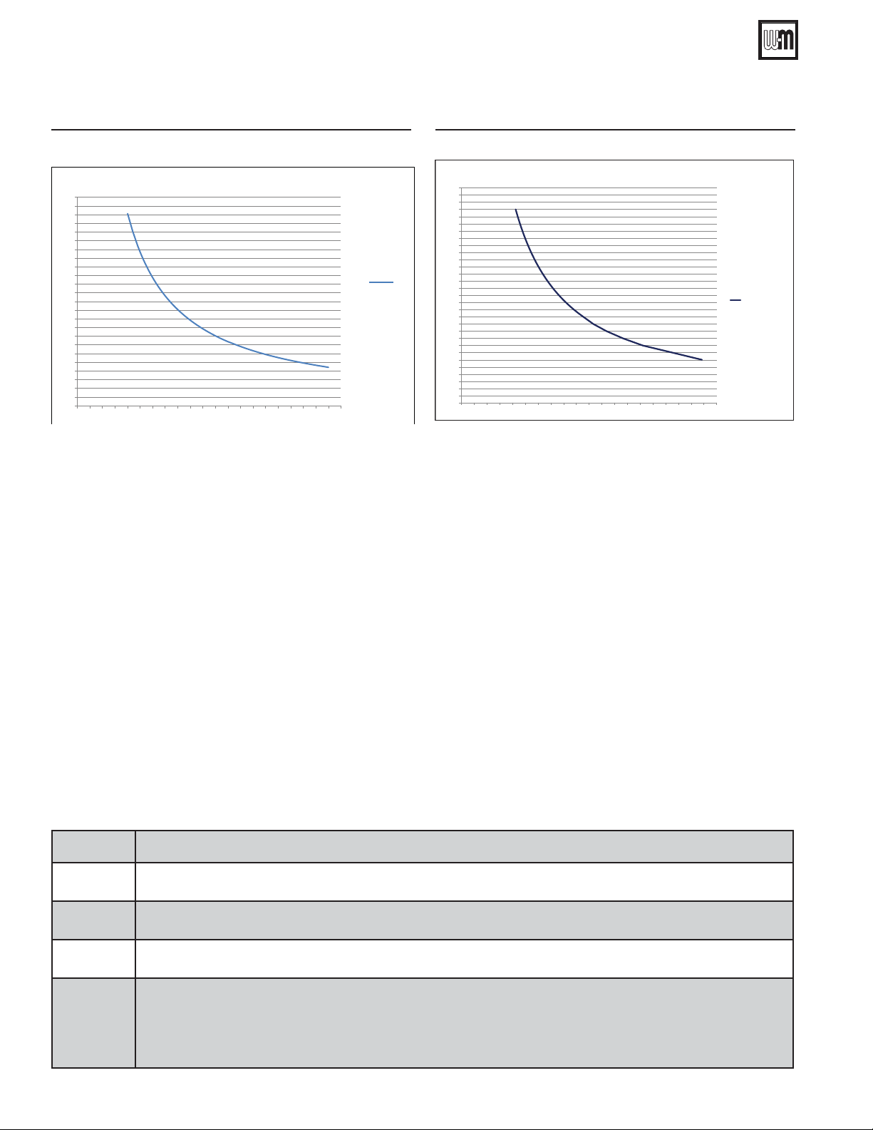
AquaBalance® SERIES 2 WALL MOUNT GAS-FIRED WATER BOILER — Boiler Manual
27 DHW Settings (Combi Only) (continued)
Figure 91 DHW curve - AquaBalance® 120 Figure 92 DHW curve - AquaBalance® 155
AquaBalance 155 -
G.P.M.
12
11.5
11
10.5
10
9.5
9
8.5
8
7.5
7
6.5
6
5.5
5
4.5
4
3.5
3
2.5
2
1.5
1
0.5
0
0 5 10 15 20 25 30 35 40 45 50 55 60 65 70 75 80 85 90 95 100 105
AquaBalance 120 - DHW PRODUCTION
AquaBalance 120
Delta T (ºF)
G.P.M.
15
14.5
14
13.5
13
12.5
12
11.5
11
10.5
10
9.5
9
8.5
8
7.5
7
6.5
6
5.5
5
4.5
4
3.5
3
2.5
2
1.5
1
0.5
0
0 5 10 15 20 25 30 35 40 45 50 55 60 65 70 75 80 85 90 95 100
Freestyle 155 - DHW PRODUCTION
Freestyle 155
AquaBalance 155
Delta T (ºF)
The “D” Parameter codes below are part of the normal Control Operation and typically appear during Start Up.
This a “Timed” or “Auto Recycle” event.
• D1….the boiler is / has finished the call for Domestic Water heating, and is in the transition to either
standby mode or central heating mode.
• D2….the boiler has reached the required water set point, and the firing has stopped / with a call for Central Heating still applied by the T-Stat to the boiler. Circulators will continue to operate and the boiler is
monitoring the two internal water sensors (return & discharge) waiting for a water “Delta-T” to return…at
that time the boiler will re-fire if need be.
• D3….the boiler has made 3 tries for ignition and has failed to ignite. A re-trial ignition cycle / delay is in
effect for 3 more tries to ignite/restart boiler operation.
Parameter Description
D1
D2
After cycle of Domestic water mode, D1 will be displayed.
When required boiler water set - point is reached D2 will be displayed.
64
D3
After an attempt for ignition, re-trial ignition delay is in effect (D3 is displayed).
* Check for proper fuel supply.
5HPRYHDQGFKHFNLJQLWRUIRUSURSHUJDS´UHSODFHLIGLV¿JXUHGFKHFNFRPEXVWLRQVHWWLQJ1DWXUDOJDVRU/3
* Insure condensate is draining properly.
* Insure venting size and length are correct and unobstructed.
Part number 550-100-325/0718
Page 65
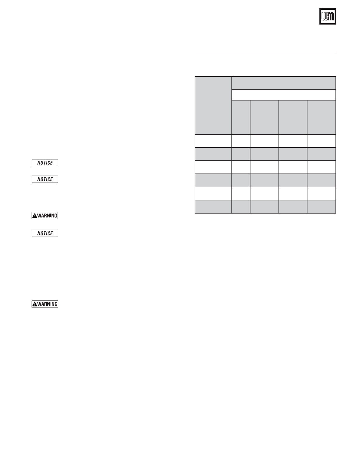
AquaBalance® SERIES 2 WALL MOUNT GAS-FIRED WATER BOILER — Boiler Manual
28 Standard Altitude
Standard Altitude Boiler Adjustment
(below 4,500’ installations)
1. Press DHW- and DHW+ buttons together for 10 seconds
to enter the parameter setup menu. The standard values
for parameter “b04”, “ b05” and “b06”, are shown in Table
above.
2. Roll down the menu by pressing the CH button until the
parameter “b04” is on the screen.
3. Set parameter “b04” to parameter in Table above.
4. Repeat steps 2 and 3 above to also adjust parameter “b05”
and “b06”, according to Table above.
5. Press DHW- and DHW+ buttons together for 10 seconds
to leave the menu. The values are automatically saved.
The Ignition speeds are the same for Standard
and High Altitude, there’s no need to change.
In USA Input rates are derated 4% for each 1000
ft. above sea level, beyond 2000 ft. in accordance
with National Fuel Gas Code, ANSI Z223.1/NFPA
54 -latest edition, and/or the Natural Gas and
Propane Installation Code, CAN/CSA B149.1.
For elevations above 10,000 feet, please contact
Weil-McLain Technical Support for details.
Figure 93 STANDARD Altitude Fan Speeds
(for below 4,500’ installations)
Model
AB-80-N
AB-80-LP
AB-120-N
AB-120-LP
AB-155-N
AB-155-LP
Low
Fire
(b06)
40 80% 155 155
40 80% 145 145
40 60% 200 200
40 60% 185 185
39 50% 205 205
40 50% 210 210
Standard Altitude
Fan Speed Hz
Ignition
(Can't
Change
- Needs
PC)
High Fire
In
CH Mode
(b05)
High Fire
In
DHW
Mode
(b04)
In Canada, Input rates are derated 10% for altitudes
of 2000 ft. to 4500 ft. above sea level. Please use
appropriate Fan Speed Settings for High Altitude
provided in this manual.
In Canada for elevation beyond 4500 feet. please
consult Provincial Authorities having jurisdiction
and/or local codes.
Perform Boiler Manual Start-up
Follow all instructions in the start-up section
for boiler start-up after converting for High
Altitude. Because the boiler has been changed,
you must verify correct operation, including
checking combustion with test instruments
both at high fire and low fire as described in
the this manual, pages 77, 78 & 79.
Check the correct ignition sequence of the
boiler after the conversion, as in page 86.
Failure to comply could result in severe per-
sonal injury, death or substantial property
damage.
Part number 550-100-325/0718
65
Page 66
AquaBalance® SERIES 2 WALL MOUNT GAS-FIRED WATER BOILER — Boiler Manual
28 High Altitude
HIGH ALTITUDE BOILER ADJUSTMENT
(above 4,500’ installations)
1. Press DHW- and DHW+ buttons together for 10 seconds
to enter the parameter setup menu. The standard values for
parameter “b04”, “ b05” and “b06”, are shown in Table below
and the following pages.
2. Roll down the menu by pressing the CH button until the
parameter “b04” is on the screen.
3. Set parameter “b04” to parameter in Table above.
4. Repeat steps 2 and 3 above to also adjust parameter “b05”
and “b06”, according to Table above.
5. Press DHW- and DHW+ buttons together for 10 seconds to
leave the menu. The values are automatically saved.
The Ignition speeds are the same for Standard and
High Altitude, there’s no need to change.
Figure 94 High Altitude Fan Speeds for AquaBalance® 80 boilers
80KBTU - Natural Gas
LOW FIRE HIGH FIRE (CH & DHW)
ALTITUDE
0 - 2,000' 40 8.0 - 9.0 <20 155 9.0 - 9.5 <110
Blower Speed
(b06)
CO2 (%) CO (PPM)
In USA Input rates are derated 4% for each 1000
ft. above sea level, beyond 2000 ft. in accordance
with National Fuel Gas Code, ANSI Z223.1/NFPA
54 - latest edition, and/or the Natural Gas and
Propane Installation Code, CAN/CSA B149.1.
For elevations above 10,000 feet, please contact
Weil-McLain Technical Support for details.
In Canada, Input rates are derated 10% for altitudes
of 2000 ft. to 4500 ft. above sea level. Please use
appropriate Fan Speed Settings for High Altitude
provided in this manual.
In Canada for elevation beyond 4500 feet. please
consult Provincial Authorities having jurisdiction
and/or local codes.
Blower Speed
(b04 & b05)
CO2 (%) CO (PPM)
2,000' - 4,000' 42 8.0 - 9.0 <20 155 9.0 - 9.5 <110
4,000'-5,000' 43 8.0 - 9.0 <20 155 9.0 - 9.5 <110
5,000'-6,000' 44 8.0 - 9.0 <20 155 9.0 - 9.5 <110
6,000' - 7,000' 45 8.0 - 9.0 <20 155 9.0 - 9.5 <110
7,000' - 8,000' 46 8.0 - 9.0 <20 155 9.0 - 9.5 <110
8,000' - 9,000' 47 8.0 - 9.0 <20 155 9.0 - 9.5 <110
9,000' - 10,000' 48 8.0 - 9.0 <20 155 9.0 - 9.5 <110
80KBTU - LP Gas
LOW FIRE HIGH FIRE (CH & DHW)
ALTITUDE
0 - 2,000' 40 9.0 - 9.8 <20 145 10.2 - 10.7 <110
2,000' - 4,000' 42 9.0 - 9.8 <20 145 10.2 - 10.7 <110
4,000'-5,000' 43 9.0 - 9.8 <20 145 10.2 - 10.7 <110
5,000'-6,000' 44 9.0 - 9.8 <20 145 10.2 - 10.7 <110
6,000' - 7,000' 45 9.0 - 9.8 <20 145 10.2 - 10.7 <110
Blower Speed
(b06)
CO2 (%) CO (PPM)
Blower Speed
(b04 & b05)
CO2 (%) CO (PPM)
7,000' - 8,000' 46 9.0 - 9.8 <20 145 10.2 - 10.7 <150
8,000' - 9,000' 47 9.0 - 9.8 <20 145 10.2 - 10.7 <150
9,000' - 10,000' 48 9.0 - 9.8 <20 145 10.2 - 10.7 <150
66
Part number 550-100-325/0718
Page 67
AquaBalance® SERIES 2 WALL MOUNT GAS-FIRED WATER BOILER — Boiler Manual
28 High Altitude Blower Speeds
Figure 95 HIGH Altitude Fan Speeds for AquaBalance® 120 boilers
120KBTU - Natural Gas
LOW FIRE HIGH FIRE (CH & DHW)
ALTITUDE
0 - 2,000' 40 8.0 - 9.0 <20 200 9.0 - 9.5 <110
2,000' - 4,000' 43 8.0 - 9.0 <20 200 9.0 - 9.5 <110
4,000'-5,000' 46 8.0 - 8.5 <20 200 8.7 - 9.0 <150
5,000'-6,000' 49 8.0 - 8.5 <20 200 8.7 - 9.0 <150
6,000' - 7,000' 51 8.0 - 8.5 <20 200 8.7 - 9.0 <150
7,000' - 8,000' 52 8.0 - 8.5 <20 200 8.7 - 9.0 <180
8,000' - 9,000' 53 8.0 - 8.5 <20 200 8.7 - 9.0 <180
9,000' - 10,000' 54 8.0 - 8.5 <20 200 8.7 - 9.0 <180
Blower Speed
(b06)
CO2 (%) CO (PPM)
Blower Speed
(b04 & b05)
CO2 (%) CO (PPM)
120KBTU - LP Gas
LOW FIRE HIGH FIRE (CH & DHW)
ALTITUDE
0 - 2,000' 40 9.0 - 9.8 <20 185 10.2 - 10.7 <110
2,000' - 4,000' 43 9.0 - 9.8 <20 185 10.2 - 10.7 <110
4,000'-5,000' 46 9.0 - 9.4 <20 185 10.0 - 10.2 <180
5,000'-6,000' 49 9.0 - 9.4 <20 185 10.0 - 10.2 <180
6,000' - 7,000' 51 9.0 - 9.4 <20 185 10.0 - 10.2 <180
7,000' - 8,000' 52 9.0 - 9.4 <20 185 10.0 - 10.2 <200
8,000' - 9,000' 53 9.0 - 9.4 <20 185 10.0 - 10.2 <200
9,000' - 10,000' 54 9.0 - 9.4 <20 185 10.0 - 10.2 <200
Blower Speed
(b06)
CO2 (%) CO (PPM)
Blower Speed
(b04 & b05)
CO2 (%) CO (PPM)
Part number 550-100-325/0718
67
Page 68
AquaBalance® SERIES 2 WALL MOUNT GAS-FIRED WATER BOILER — Boiler Manual
28 High Altitude Blower Speeds
Figure 96 HIGH Altitude Fan Speeds for AquaBalance® 155 boilers
155KBTU - Natural Gas
LOW FIRE HIGH FIRE (CH & DHW)
ALTITUDE
0 - 2,000' 39 8.0 - 9.0 <7 205 9.0 - 9.5 <120
2,000' - 4,000' 40 8.0 - 9.0 <7 205 9.0 - 9.5 <120
4,000'-5,000' 41 8.0 - 8.5 <10 205 8.7 - 9.0 <150
5,000'-6,000' 42 8.0 - 8.5 <10 205 8.7 - 9.0 <150
6,000' - 7,000' 43 8.0 - 8.5 <10 205 8.7 - 9.0 <150
7,000' - 8,000' 45 8.0 - 8.5 <10 205 8.7 - 9.0 <180
8,000' - 9,000' 46 8.0 - 8.5 <10 205 8.7 - 9.0 <180
9,000' - 10,000' 48 8.0 - 8.5 <10 205 8.7 - 9.0 <180
Blower Speed
(b06)
CO2 (%) CO (PPM)
Blower Speed
(b04 & b05)
CO2 (%) CO (PPM)
155KBTU - LP Gas
LOW FIRE HIGH FIRE (CH & DHW)
ALTITUDE
0 - 2,000' 40 9.0 - 9.8 <7 207 10.2 - 10.7 <120
2,000' - 4,000' 42 9.0 - 9.8 <7 207 10.2 - 10.7 <120
4,000'-5,000' 43 9.3 - 9.5 <10 207 9.7 - 9.9 <150
5,000'-6,000' 44 9.3 - 9.5 <10 207 9.7 - 9.9 <150
6,000' - 7,000' 45 9.3 - 9.5 <10 207 9.7 - 9.9 <150
7,000' - 8,000' 47 9.3 - 9.5 <10 207 9.7 - 9.9 <180
8,000' - 9,000' 48 9.3 - 9.5 <10 207 9.7 - 9.9 <180
9,000' - 10,000' 50 9.3 - 9.5 <10 207 9.7 - 9.9 <180
Blower Speed
(b06)
CO2 (%) CO (PPM)
Blower Speed
(b04 & b05)
CO2 (%) CO (PPM)
Perform Boiler Manual Start-up
Follow all instructions in the start-up section for boiler start-up after convert-
ing for High Altitude. Because the boiler has been changed, you must verify cor-
rect operation, including checking combustion with test instruments both
at high fire and low fire as described in the this manual, pages 77, 78 & 79.
Check the correct ignition sequence of the boiler after the conversion, as in page 86.
68
Failure to comply could result in severe personal injury, death or substantial property damage.
Part number 550-100-325/0718
Page 69
AquaBalance® SERIES 2 WALL MOUNT GAS-FIRED WATER BOILER — Boiler Manual
29 Startup — Quick Start Guide using default settings
Figure 97 Quick Start Guide - Default control settings (see instructions and figures on pages 58-68).
QUICK START GUIDE
After you have completed the installation of the Combi or Heating Only model by the instructions provided in
this manual, pages 5-71 insure the following first before you proceed:
All gas lines are connected and tested for leaks, and if the boiler is to operate on LP fuel, and the unit has been
converted properly from Natural gas to Liquefied Petroleum (Propane) gas and set up as directed in the boiler
manual.
All water piping is installed correctly and free of leaks with the proper accessories; proper sized expansion tank,
water feed valve adjusted, low water cut-off devices installed and tested, all operation control exterior to the boiler
installed such as thermostats, and zone control panels.
• Sentinel X100 Inhibitor has been added and the water has been checked with the test kit.
• Condensate trap has been filled with water.
• Electrical connection for the boiler is grounded and has correct polarity.
• Venting and Intake Air Piping is all secure, sealed and installed as instructed in this boiler manual.
• Central Heating only boilers, Outdoor sensor MUST be installed and connected to the boiler control.
(See page 49)
System start
1
Push eco / comfort / Power button; to start boiler
NOTE: if A-16 error code is displayed (Central Heating Only boiler) when unit is powered up,
the outdoor sensor is not installed. Install outdoor sensor and push the reset button to reset
2
error code. A faulty outdoor sensor will give an “F-39” error code.
The Outdoor sensor must be installed unless specifically exempted in the Energy Act statement on page 131.
3
04 “shows on the display” (control software version)
4
FH “shows on the display”
5
With no “call for heat”
To Change “Central Heating water temperature set-point” (from 68 F to 190 degrees F) use the bottom set
6
of “+” or “–” keys to raise or lower the set point temperature.
To change “Domestic water temperature set-point” (Combi Boiler set from 104 F to 131 degrees F )
7
NOTE: Insure that the operating temperature is at a safe set-point temperature. Use the top set of “+” or “–” keys to raise or lower the set point.
(Blower /inducer operating in purge mode of combustion chamber and venting for 5 minutes).
(current boiler water temperature will be shown in degrees F).
To Change “Control Selection for vent material” See instructions on page 32. This is necessary only if using a
8
venting material other than the default PVC.
Part number 550-100-325/0718
69
Page 70
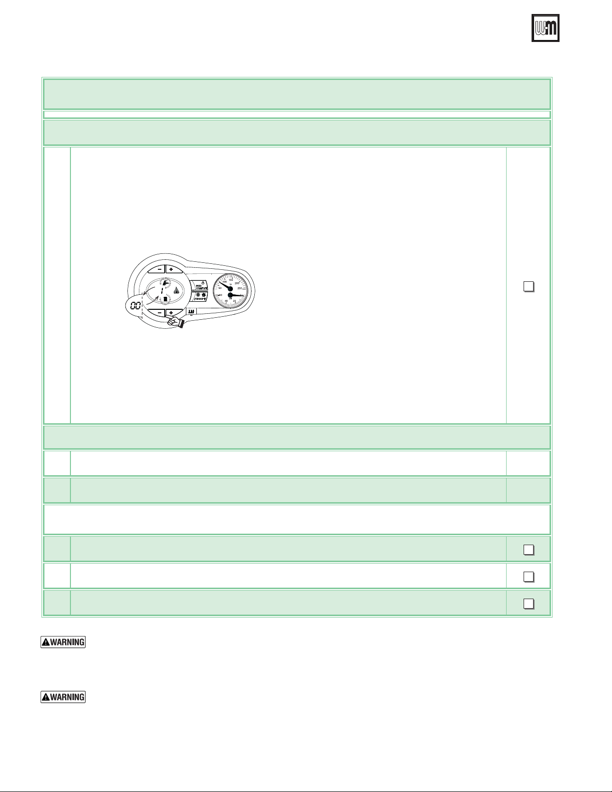
AquaBalance® SERIES 2 WALL MOUNT GAS-FIRED WATER BOILER — Boiler Manual
29 Startup — Quick Start Guide using default settings (continued)
QUICK START GUIDE
System start (continued)
“Test Mode Operation”
Proceed to put the boiler into operation as follows:
1. To start, create a demand for heat, open up a hot water faucet or turn up the thermostat.
2. To operate the boiler in test mode, press the CH “-” and “+” keys together for 5 seconds
(See below and Figure 100, page 75) to activate the TEST mode.
3. The boiler lights at the maximum heating 100% rate displayed on the LCD display.
8
4. The high fire (large) flame symbol will be displayed once the boiler has lit.
5. Use DHW “_” button to drop firing rate to low fire.
6. To exit the “Test mode”, press the CH keys (Items 3 and 4, Figure 76, page 58) together for 5 seconds, or
leave the boiler to automatically switch off after 15 minutes or stopping DHW flow.
7. This TEST procedure is used to check/adjust combustion CO and CO
and Figure 106, page 79.
Liquefied Petroleum (Propane) Gas — Propane conversion kit (optional - sold separately, see Figure 159, page 116 .
High altitude — High altitude (over 4,500 feet) requires only changing the altitude setting on the control. (See page 66).
Equipment that maybe required for installation
Digital or U-tube manometer for checking gas line pressure
per specifications, Figure 103, page 78
2
Volt-ohmmeter may be required for troubleshooting
Combustion Analyzer to verify and adjust combustion
This unit must only be used for its intended purpose. This unit is designed to heat water to a temperature below
boiling point and must be connected to a heating system and/or a water supply system for domestic use, compatible
with its performance, characteristics and heating capacity. Any other use is deemed improper.
Incorrect installation can cause damage or injury for which the manufacturer cannot be deemed responsible.
The boiler contains ceramic fiber and fiberglass materials. Use care when handling these materials per instructions
on page 82 of this manual. Failure to comply could result in severe personal injury.
Pay attention when handling the boiler insulation panels as they contain materials that could irritate the skin. No
part of the boiler contains asbestos, mercury or Chlorofluorocarbons (CFC’s).
70
Part number 550-100-325/0718
Page 71

AquaBalance® SERIES 2 WALL MOUNT GAS-FIRED WATER BOILER — Boiler Manual
29 Startup
CIRCULATOR EXERCISING and
FREEZE PROTECTION
CIRCULATOR EXERCISING
The control will automatically start the circulator output and run
for 10 seconds for each 72-hour period of inactivity.
FREEZE PROTECTION
This function automatically fires the boiler and starts the
HEAT circulator when the heat exchanger sensor detects a
temperature less than 40 °F. The circulator turns off when the
temperature rises above 45 °F.
Clean system to remove sediment
1. You must thoroughly flush the system (without boiler
connected) to remove sediment. The high-efficiency heat
exchanger can be damaged by buildup or corrosion due
to sediment.
If the system needs to be cleaned, use only Sen-
tinel X400 cleaner, available from Weil-McLain.
See Figure 160, page 117 for information. Follow
instructions supplied with the X400 cleaner and
cleaning instructions on page 111. For zoned
systems, flush each zone separately through a
purge valve. (If purge valves and isolation valves
are not already installed, install them to properly
clean the system).
2. Flush system until water runs clean and you are sure piping
is free of sediment.
Do not use petroleum-based clean-
ing or sealing compounds in boiler system. Damage to elastomer seals
and gaskets in system could occur, resulting in substantial property damage.
Before filling the boiler and system with water,
verify the following. Boiler corrosion can occur.
Failure to comply could result in boiler
failure or unreliable operation.
Water chemistry
Hardness less than 7 grains
1. Consult local water treatment companies for unusually hard
water areas (above 7 grains hardness).
Chloride concentration must be
LESS THAN 50 ppm
1. Filling with chlorinated fresh water should be acceptable since
drinking water chloride levels are typically less than 5 ppm.
2. Do not use the boiler to directly heat swimming pool or spa
water.
3. Do not fill boiler or operate with water containing chloride
in excess of 50 ppm.
Verify that the water chemistry meets the limita-
tions and requirements of all other equipment in
the system.
Antifreeze
1. Use only antifreeze listed by Weil-McLain as suitable for
use with Combi boilers. See Figure 160, page 117 for information.
2. See Replacement parts at the end of this manual for
part numbers to obtain antifreeze through a Weil-McLain
distributor.
Use the correct amount of antifreeze
1. Determine the freezing temperature needed (to protect
against lowest likely temperature the system water will encounter).
2. Find the antifreeze concentration by volume needed for this
temperature from the antifreeze manufacturer’s data on the
antifreeze container.
3. Add up the volume (gallons) of all system piping and components, including the expansion tank and boiler.
a. Boiler water content is listed in Figure 173, page 130.
b. Remember to include expansion tank water content.
4. Multiply this volume by the (percent) antifreeze needed to
find the number of gallons of antifreeze to add.
Fill and test water system
1. Fill system only after ensuring the water meets the requirements of this manual.
2. Close manual and automatic air vents and boiler drain valve.
3. Fill to correct system pressure. Correct pressure will vary
with each application.
a. Typical cold water for a residential system is 12 psi mini-
Water pH between 7.0 and 8.5
1. Maintain boiler water pH between 7.0 and 8.5. Check with
litmus paper or have chemically analyzed by water treatment company.
2. If pH differs from above, consult local water treatment
company for treatment needed.
Part number 550-100-325/0718
Boiler water pressure switch is set for 9 psi (±2)
minimum pressure. A low water pressure will give
“F37” fault code.
b. Pressure will rise when boiler is turned on and system
water temperature increases. Operating pressure must
never exceed 25 PSIG.
4. At initial fill and during boiler startup and testing, check
system thoroughly for any leaks. Repair all leaks before proceeding further.
71
Page 72

AquaBalance® SERIES 2 WALL MOUNT GAS-FIRED WATER BOILER — Boiler Manual
29 Startup (continued)
Eliminate all system leaks. Continual fresh make-
up water will reduce boiler life. Minerals can
build up in the heat exchanger, reducing heat
transfer, overheating heat exchanger, and causing
heat exchanger failure.
Purge air from water system
1. Connect a hose to the drain valve (see drain valves, item
10, in piping diagrams beginning on page 9). Route hose
to an area where water can drain and be seen.
2. Close the boiler or system isolation valve between the drain
valve and fill connection to the system.
3. Close zone isolation valves.
4. Open quick-fill valve on cold water make-up line.
5. Open drain valve.
6. One zone at a time, open the isolation valves. Allow
water to run through the zone, pushing out the air. Run
until no noticeable air flow is present. Close the zone isolation valves and proceed with the next zone. Follow this
procedure until all zones are purged. Follow the same
procedure to purge air from the boiler and its internal
piping.
7. Close the quick-fill water valve and drain valve and remove
the hose. Open all isolation valves. Watch that system pressure rises to correct cold-fill pressure.
8. Using the manual air vents located throughout the system.
9. If purge valves are not installed in system, open manual
air vents in system one at a time, beginning with lowest
floor. Close vent when water squirts out. Repeat with
remaining vents.
10. Open automatic air vent (diaphragm-type or bladder-type
expansion tank systems only) one turn.
11. Starting on the lowest floor, open air vents one at a time
until water squirts out.
12. Repeat with remaining vents.
13. Refill to correct pressure.
14. When the boiler is turned on it cycles the pump to eliminate
any air in system, per Figure 80, page 60.
Freeze protection (if used)
Follow these guidelines to prevent possibility of
severe personal injury, death or substantial property
damage:
Thoroughly flush any system that has used
In addition to antifreeze and inhibitor, use and
If using freeze protection fluid with automatic fill,
Use only the products listed by Weil-McLain for
use with this boiler. See page 117 for information.
glycol
before installing the new boiler.
Review the material safety data sheets (MSDS)
are available online. The MSDS contains information on potential hazards and first aid procedures
for exposure or ingestion.
Check antifreeze inhibitor level at least annually
. Glycol concentration and inhibitor levels
may change over time. Add antifreeze to increase
concentration if necessary. Add inhibitor as needed
to bring to acceptable level, using inhibitor test kit
to verify.
maintain minimum level of Sentinel X100 inhibitor
as directed on this page.
install a water meter to monitor water make-up.
Freeze protection fluid may leak before the water begins to leak, causing concentration to drop, reducing
the freeze protection level.
DO NOT exceed 50% antifreeze by volume.
Antifreeze moves more sluggishly than water and
can interfere with heat transfer. At antifreeze concentrations higher than 50%, sludge can develop in
the boiler, potentially causing damage to the heat
exchanger.
72
Use only antifreeze recommended by
Clean the system before filling. Always drain
and flush the system thoroughly before filling with
antifreeze. Sludge, iron oxide deposits and other
sediment in the system inhibit flow and can cause
rapid breakdown of inhibitors.
Weil-McLain.
Weil-McLain provides information for application
of the antifreeze products listed in this document
only for use in boilers. Do not apply these products
or instructions for other applications. Local codes
may require a backflow preventer or actual disconnection from city water supply.
Part number 550-100-325/0718
Page 73
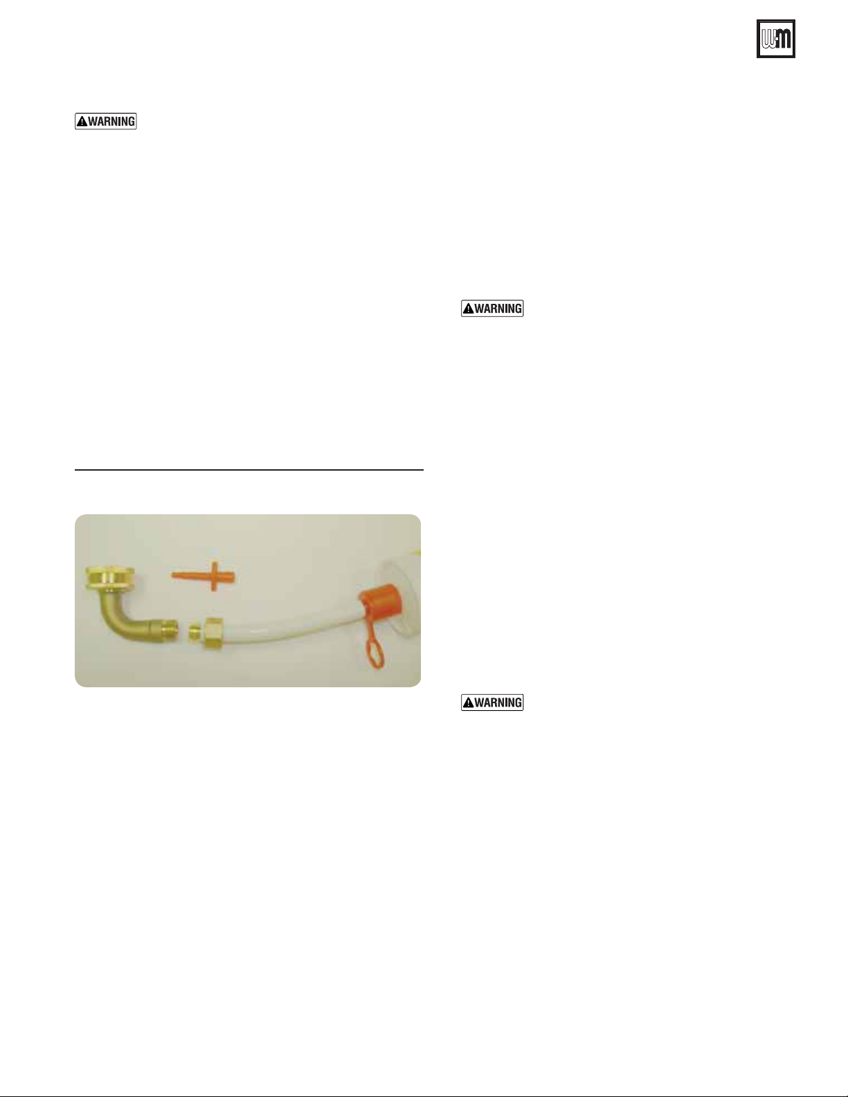
AquaBalance® SERIES 2 WALL MOUNT GAS-FIRED WATER BOILER — Boiler Manual
29 Startup (continued)
X100 inhibitor is required
1. It is required that the boiler have Sentinel X100 inhibitor added to the system to prevent damage to the boilers’
heat exchanger. Failure to comply may result in accelerated
corrosion of the heat exchanger and system components.
See Replacement Parts section at the end of this manual for
ordering information.
2. After filling the system as directed in this manual, and the air
purge has been completed, release the system water pressure
to 0 psi. Drain a small amount of water out of a convenient
boiler drain to insure the system water pressure is at 0 psi.
Use a (field supplied-if needed) Dishwasher elbow / hose
3/4 to 3/8 compression adapter (See Figure 98 below) to the
white Sentinel hose, and screw it to the tube of Sentinel X100.
Insert it into your caulk gun, and fit the washing machine
hose adapter to a boiler drain connection. Open the drain,
and inject the complete tube of X100 to the system. Close the
drain valve, and remove the injection fitting.
Figure 98 Hardware fittings to add Sentinel to boiler
Check inhibitor concentration
annually
1. Test the pH of a sample of system water at least annually.
The pH of the water mixture must be between 7.0 and 8.5.
(Or use the Sentinel inhibitor test kit to check concentration.)
2. If pH is outside this range (or inhibitor test kit indicates
low level), the inhibitor level may not be sufficient to prevent corrosion.
3. Test antifreeze concentration.
Test antifreeze concentration at least annually.
If concentration is low, add antifreeze or drain
system and refill with correct mixture.
4. Follow instructions on antifreeze container to determine
the amount of antifreeze needed.
volume concentration of antifreeze.
Check inhibitor level after adjustments are made.
DO NOT exceed 50% by
Check thermostat circuits
5. Disconnect wires connected to the thermostat terminals
(see Field wiring, beginning on page 48 for low voltage
terminal locations and application information). Mark
the wires before removing to avoid wiring errors when
re-connecting them.
6. Connect a voltmeter across each pair of incoming wires.
Close each thermostat, zone valve and relay in the external
circuits one at a time and check the voltmeter reading across
the incoming wires.
There should NEVER be a voltage reading.
7.
8. If a voltage does occur under any condition, check and
correct the external wiring.
3. Fill system water to required pressure, and start a heating
zone to circulate system water. Allow time for the water to
circulate and mix. Then check the inhibitor level with a test
kit. Add additional inhibitor if necessary.
Check/verify water chemistry
1. The system may have residual substances that could affect
water chemistry.
2. After the system has been filled and leak tested, verify water
pH and chloride concentrations are acceptable.
3. Verify antifreeze concentration, if used.
4. Follow the instructions on the Sentinel test kit to sample the
system water and verify inhibitor concentration.
Part number 550-100-325/0718
DO NOT connect the thermostat terminals
to 3-wire zone valves
trol damage.
9. Once the external thermostat circuit wiring is checked and
corrected if necessary, reconnect the external thermostat
circuit wires.
. This could cause con-
73
Page 74
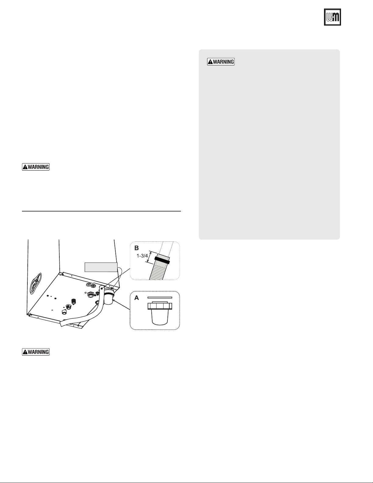
AquaBalance® SERIES 2 WALL MOUNT GAS-FIRED WATER BOILER — Boiler Manual
30 6WDUWXS²¿QDOFKHFNV
Inspect/fill condensate system
Inspect/check condensate lines and fittings
1. Inspect the condensate drain line, condensate PVC fittings and
condensate trap. (See page 45 for component locations).
Fill condensate trap with water
1. Loosen the nut that secures the condensate trap body to the
boiler condensate connection (see Figure 99). Pull the trap down
to disengage from heat exchanger. Pull the trap body forward
enough to allow pouring water into the top of the trap.
2. Fill the trap with fresh water until water begins to run into the
condensate drain tube.
3. Reattach the trap body by sliding onto the boiler condensate
outlet, then retightening the trap body nut.
The condensate trap must be filled with water during
all times of boiler operation to avoid flue gas emission
from the condensate drain line. Failure to fill the trap
could result in severe personal injury or death.
Figure 99 Disconnect condensate trap assembly to fill
trap body with water
Before starting the boiler, and during initial operation, use a leak detector or smell near the floor and
around the boiler for gas odorant or any unusual
odor. Remove boiler jacket door and smell the interior of the boiler jacket.
if there is any indication of a gas leak. Repair any
leak at once
DO NOT adjust or attempt to measure gas valve
outlet pressure.
correct outlet pressure. This setting is suitable for
natural gas and propane, requiring no field adjustment. Attempting to alter or measure the gas valve
outlet pressure could result in damage to the valve,
causing potential severe personal injury, death or
substantial property damage.
Propane boilers only — Your propane supplier
mixes an odorant with the propane to make its presence detectable. In some instances, the odorant can
fade, and the gas may no longer have an odor. Before startup (and periodically thereafter), have the
propane supplier verify the correct odorant level in
the gas.
Check for gas leaks
Do not proceed with startup
.
The gas valve is factory-set for the
Nut
If it is suspected that the condensate drain connection is or was blocked, then boiler components
like the gas valve, blower venturi, igniter and heat
exchanger need to be inspected. Check for damages
occurring from water accumulation in this cabinet.
Any damaged components need to be replaced.
Failure to replace water damaged components
could result in severe personal injury or death.
74
Part number 550-100-325/0718
Page 75
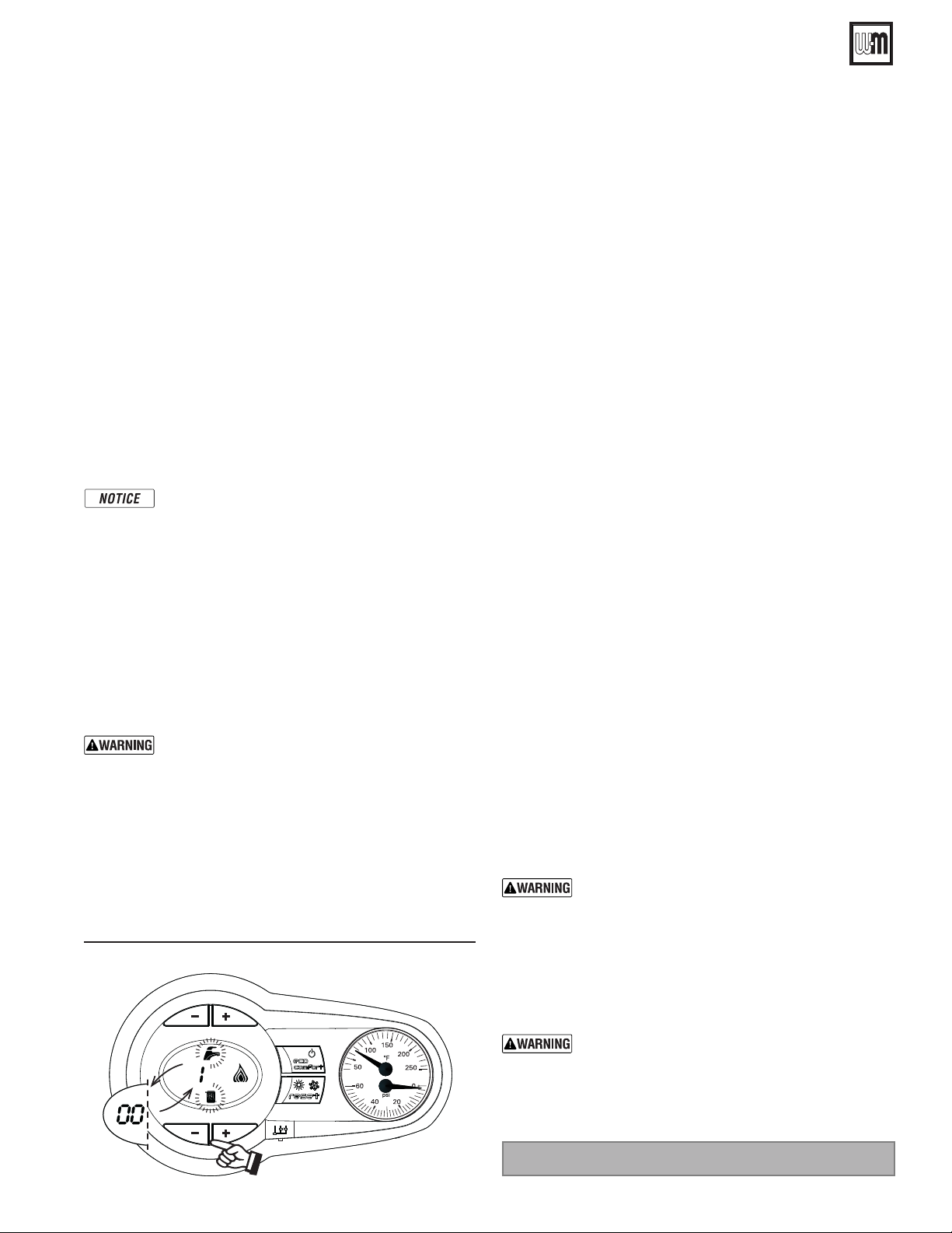
AquaBalance® SERIES 2 WALL MOUNT GAS-FIRED WATER BOILER — Boiler Manual
30 6WDUWXS²¿QDOFKHFNV (continued)
Final checks before lighting the boiler
• Open any on-off valves between boiler and the systems.
• Verify that there are no leaks of the gas system.
• Verify that the boiler and system are full of water and all
system components are correctly set for operation.
• Verify that condensate trap drain line is filled with water.
• Verify that there are no leaks in the system, DHW piping,
connections or boiler.
• Verify electrical connections are correct and securely
attached.
• Inspect vent piping and air piping for signs of deterioration from corrosion, physical damage or sagging. Verify air
piping and vent piping are intact and correctly installed
per this manual.
• Read the instructions to adjust and set up the boiler
control.
• Verify that the boiler model is set correctly in the boiler
control, and that it displays correctly.
To start the boiler
The combustion for this boiler has been
checked, adjusted and preset at the factory
for operation for Natural Gas.
Having checked:
• That the boiler has been installed in accordance with
these instructions.
• The integrity of the flue system and the flue seals.
• The integrity of the boiler combustion circuit and the
relevant seals.
1. Apply power to the boiler.
2. Follow the Operating Instructions, Figure 101, page 76.
Test Mode Operation
When entering Test mode operation the boiler will
fire without a call for heat.
Proceed to put the boiler into operation as follows:
1. To start create a demand for heat, open up a hot water faucet(s)
or turning up the thermostat. This way you will ensure that
during the “Test Mode” a heat load is created to “Dump” the
energy from the boiler.
2. To operate the boiler in test mode, press the CH “-” and
“+” keys together for 5 seconds (See below) to activate the
“TEST” mode.
Figure 100 Control in Test Mode
3. The boiler lights at the maximum heating 100% rate displayed
on the LCD display.
4. The high fire (large) flame symbol will be displayed once the
boiler has lit.
5. Use DHW “-” button to drop firing rate to low fire.
6. To exit the “TEST” mode, press the CH keys (Items 3 and
4 Figure 76, page 58) together for 5 seconds, or leave the
boiler to automatically switch off after 15 minutes or stopping DHW flow.
7. This TEST procedure is used to check/adjust combustion
CO and CO
Figure 106, page 79.
per specifications Figure 103, page 78 and
2
If boiler does not start correctly
1. Check for loose connections, blown fuse or is boiler Not
plugged in?
2. Are external limit controls (if used) open? Is boiler water
temperature above 200°F?
3. Are thermostats set below room temperature?
4. Is gas turned on at meter and boiler?
5. Is incoming gas pressure less than the minimum values given
on page 14?
6. Are boiler control settings correct for the application?
7. If none of the above corrects the problem, refer to Troubleshooting, beginning on page 85.
Check system and boiler
❏ Check water piping
1. Check system piping for leaks. If found, shut down boiler and
repair immediately. (See WARNING on page 72 regarding
failure to repair leaks.)
2. Vent any remaining air from system using manual vents. Air
in the system will interfere with circulation and cause heat
distribution problems and noise.
❏ Check vent piping and air piping
1. Check for gas-tight seal at every connection and seam of air
piping and vent piping.
Venting system must be sealed gas-tight to prevent
flue gas spillage and carbon monoxide emissions
which will result in severe personal injury or death.
❏ Check gas piping
1. Check around the boiler and inside the boiler jacket for gas
odor following the instructions in “Warning”on page 46 of
this manual.
Part number 550-100-325/0718
If you discover evidence of any gas leak, shut
down the boiler at once. Find the leak source
with bubble test and repair immediately. Do
not start boiler again until corrected. Failure
to comply could result in severe personal injury, death or substantial property damage.
CONTINUED AFTER NEXT PAGE
75
Page 76
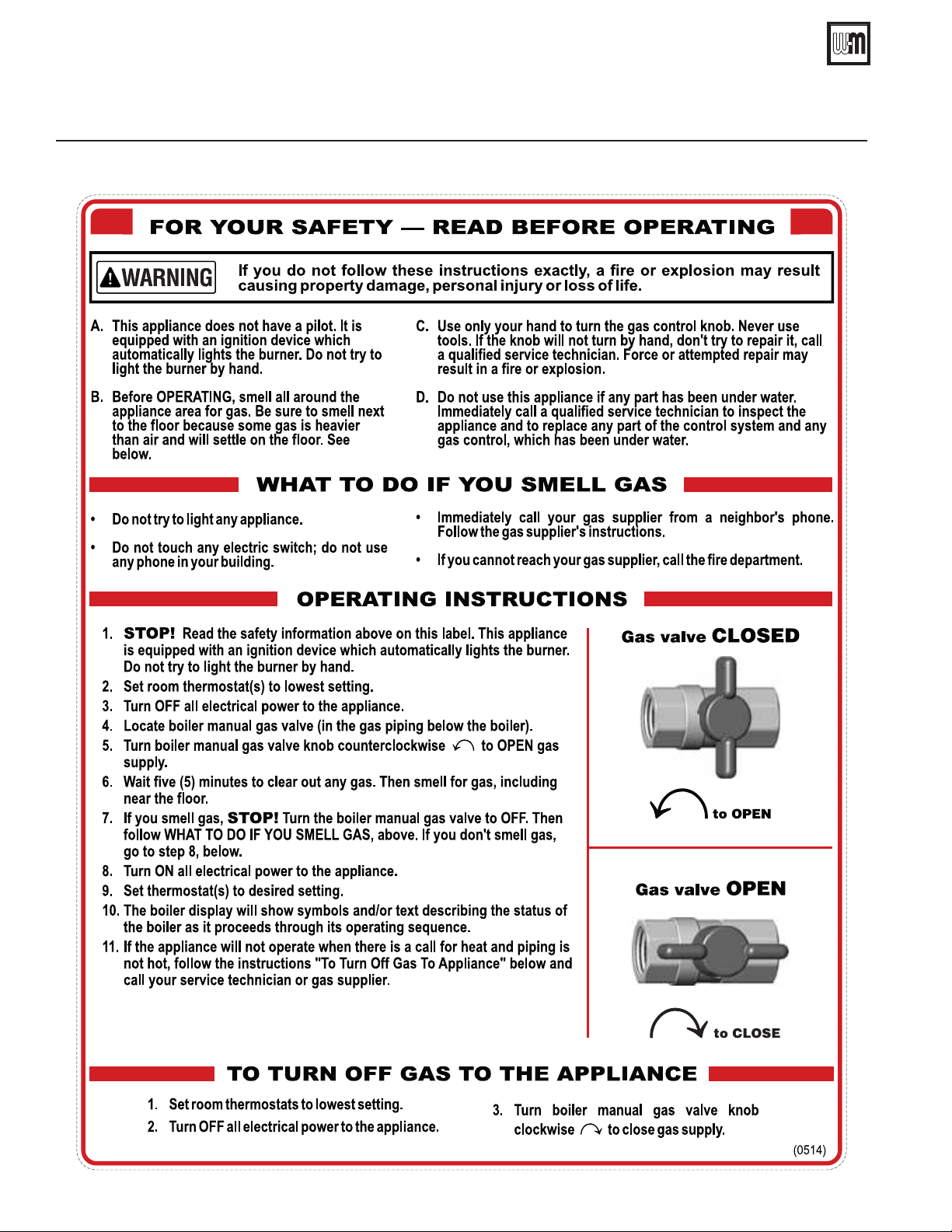
AquaBalance® SERIES 2 WALL MOUNT GAS-FIRED WATER BOILER — Boiler Manual
30 6WDUWXS²¿QDOFKHFNV (continued)
Figure 101 Operating instructions (WARNING — Verify that the control is set for the correct boiler model before
proceeding.)
76
Part number 550-100-325/0718
Page 77
AquaBalance® SERIES 2 WALL MOUNT GAS-FIRED WATER BOILER — Boiler Manual
30 6WDUWXS²¿QDOFKHFNV (continued)
❏ Propane boilers — verify conversion
1. Verify boiler has been converted for propane, See page 10.
DO NOT attempt to mea-
sure gas valve outlet pressure
DO NOT adjust or attempt to measure gas valve outlet
pressure. The gas valve is factory-set for the correct outlet
pressure. This setting is suitable for natural gas and propane,
requiring no field adjustment.
Attempting to alter or measure the gas valve outlet pressure
could result in damage to the valve, causing potential severe
personal injury, death or substantial property damage.
Boilers are shipped ready to fire natural gas ONLY.
Failure to comply could result in severe personal injury,
death or substantial property damage.
❏ Check flame & combustion with instruments
When entering Test mode operation the boiler will
fire without a call for heat.
1. To start create a demand for heat, open up a hot water faucet
or turning up the thermostat.
2. Enter into the “TEST” Mode to check combustion on High
Fire and Low Fire.
3. To operate the boiler in test mode, press the CH “-” and
“+” keys together for 5 seconds (See Figure 100, page 75)
to activate the “TEST” mode.
4. The boiler lights at the maximum heating 100% rate dis-
played on the LCD display.
5. The high fire (large) flame symbol will be displayed once the
boiler has lit.
6. Use DHW “_” button to drop firing rate to low fire.
7. To exit the “TEST” mode, press the CH keys (Items 3 and
4 Figure 76, page 58) together for 5 seconds, or leave the
boiler to automatically switch off after 15 minutes or stopping DHW flow.
8. This TEST procedure is used to check/adjust combustion
CO and CO
Figure 106, page 79.
9.
Insert combustion analyzer probe — Remove the flue access
fittings/turn to remove (see Figure 40, page 31) from the flue
pipe and insert a combustion test probe.
10. Test for CO
with or Figure 106, page 79. If results are acceptable, proceed
to step 7.
Screw Adjustment” on page 78 to set the throttle screw position. See WARNING below.
11. Measure natural gas input for High and Low Fire:
a. Operate boiler 10 minutes. Turn off other appliances.
b. At natural gas meter, measure time (in seconds) required
to use one cubic foot of gas.
Part number 550-100-325/0718
per specifications Figure 103, page 78 and
2
(or O2) and for CO. The CO2 values must comply
2
IF NOT, follow the instructions under “Throttle
If combustion at either high or low fire is out-
side the range given in Figure 103, page 78 or
Figure 106, page 79, follow the procedure given
on below, “Setting the Air/Gas Ratio Valve” for
adjusting the throttle screw on the gas valve.
If throttle screw adjustment does not correct
the problem, then shut down the boiler and
contact your local Weil-McLain Technical Support. Throttle screw adjustment must be done
only by a qualified technician, using calibrated
test instruments. Failure to comply could result
in severe personal injury, death or substantial
property damage.
c. Calculate gas input:
3600 x 1000
= Btuh
number of seconds from step b
d. Btuh calculated should approximate input rating on
boiler rating label.
12. Use the control display to navigate to Manual Test mode (see
Figure 100, page 75) and force the firing rate to LOW (low
fire). Push DHW “-” button only to drop to low fire.
13. Look at the flame through the flame inspection window. The
low fire flame should be stable and evenly distributed over
burner surface with a uniform orange color.
14. If combustion testing in low fire meets the specification
range - Exit “TEST” Mode by pressing the CH “+” and “-”
keys together for 5 seconds.
15. Reinstall the flue access fittings, (see Figure 40, page 31) used
for combustion analyzer probe and lock it in closed position.
You must reinstall the flue access fittings to the flue
adapters, to prevent flue gas spillage from the vent
adapter test ports . Failure to comply could result in
severe personal injury, death or substantial property
damage.
Table 2 Gas rate Combi and Heating Only boilers.
Gas Rate (Natural Gas)
After 10 minutes from cold
Boiler
model
AB-80
AB-120
AB-155
Maximum rate Minimum rate
ft3/h ft3/h
78.4 7.8
117.6 11.8
151.9 15.2
77
Page 78
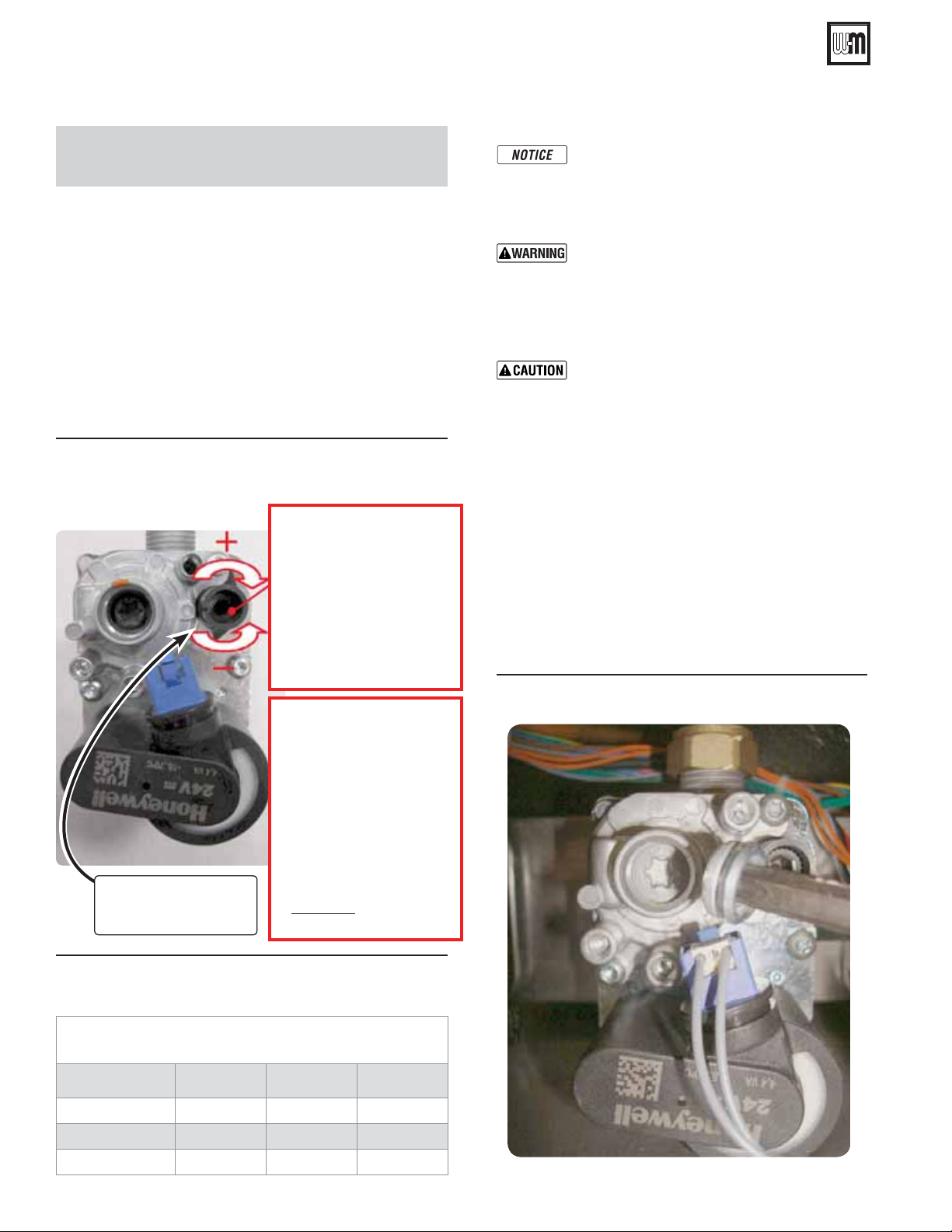
AquaBalance® SERIES 2 WALL MOUNT GAS-FIRED WATER BOILER — Boiler Manual
30 6WDUWXS²¿QDOFKHFNV (continued)
Setting the Air/Gas Ratio valve
There are two adjustments possible on the air/gas ratio valve,
the throttle setting at Maximum rate and the offset setting at
Minimum rate. If either setting is adjusted the combustion values
must be rechecked at both rates.
At Maximum Rate:
1. Adjust the boiler to Maximum rate in Figure 100, page 75,
Test Mode.
2. Wait 10 minutes to allow the boiler to stabilize.
3. Now adjust the Throttle setting (Figure 102 - screw A) until
the CO
below confirm that the CO/CO2 ratio is within limits (clockwise to increase gas).
Figure 102 Throttle adjustment screw ––
is at the correct SETTING LEVEL (see Figure 103),
2
(ONLY for use by a qualified technician, using
calibrated combustion test instruments).
CO2 Max. Regulating screw
Test at Max Power 100%
Turn clockwise (open gas)
IRU³0$;JDVÀRZ´
Turn counter-clockwise
(close gas)
IRU³0,1JDVÀRZ´
Rough start point
Using a combustion analyzer check the CO
values at low and high fire. It should be within
values from the table in Figure 103. The difference of CO2 from high fire to low fire should
NEVER be below 0.2% or above 1%.
DO NOT attempt to adjust the throttle screw
unless by a qualified technician, and with the
use of calibrated combustion test instruments.
Adjust the throttle screw only as needed to meet
the combustion values given in Figures 103 and
106, page 79.
Adjust in steps of no more than 1/8 of a turn and
wait 1 minute after each adjustment to allow the
setting to stabilize. Turning the screw too far will
cause the adjustment to reverse behavior.
4. In the event that the CO
setting level with an acceptable
2
CO/CO2 ratio cannot be obtained please contact your
Weil-McLain Technical Support for details.
5. Should you require any assistance during the set up procedure contact your Weil-McLain Technical Support if
the problem cannot be addressed with the information
provided in this manual.
6. Remove T-40 cap, see Figure 104, below, for Offset screw
adjustment.
Figure 104 Remove
wrench for adjustment
T-40 cover cap with supplied Torx
2
For LP Start up ONLY
Adjust gas valve
HIGH FIRE
screw on right with
Allen wrench turn
Counter-Clock wise
1-1/8 turns.
Throttle adjustment
screw
A
Figure 103 Maximum rate combustion values –
measured values must be within the ranges
given below
Natural Gas/LP Acceptable Combustion Range
Maximum Rate after 10 minutes from cold
Boiler Model
AB-80
AB-120
AB-155
CO/(PPM) CO
110 9.0 – 9.5 10.2 – 10.7
110 9.0 – 9.5 10.2 – 10.7
120 9.0 – 9.5 10.2 – 10.7
Final Combustion values
MUST BE checked with
Combustion Analyzer.
NG % CO2 LP %
2
78
Part number 550-100-325/0718
Page 79
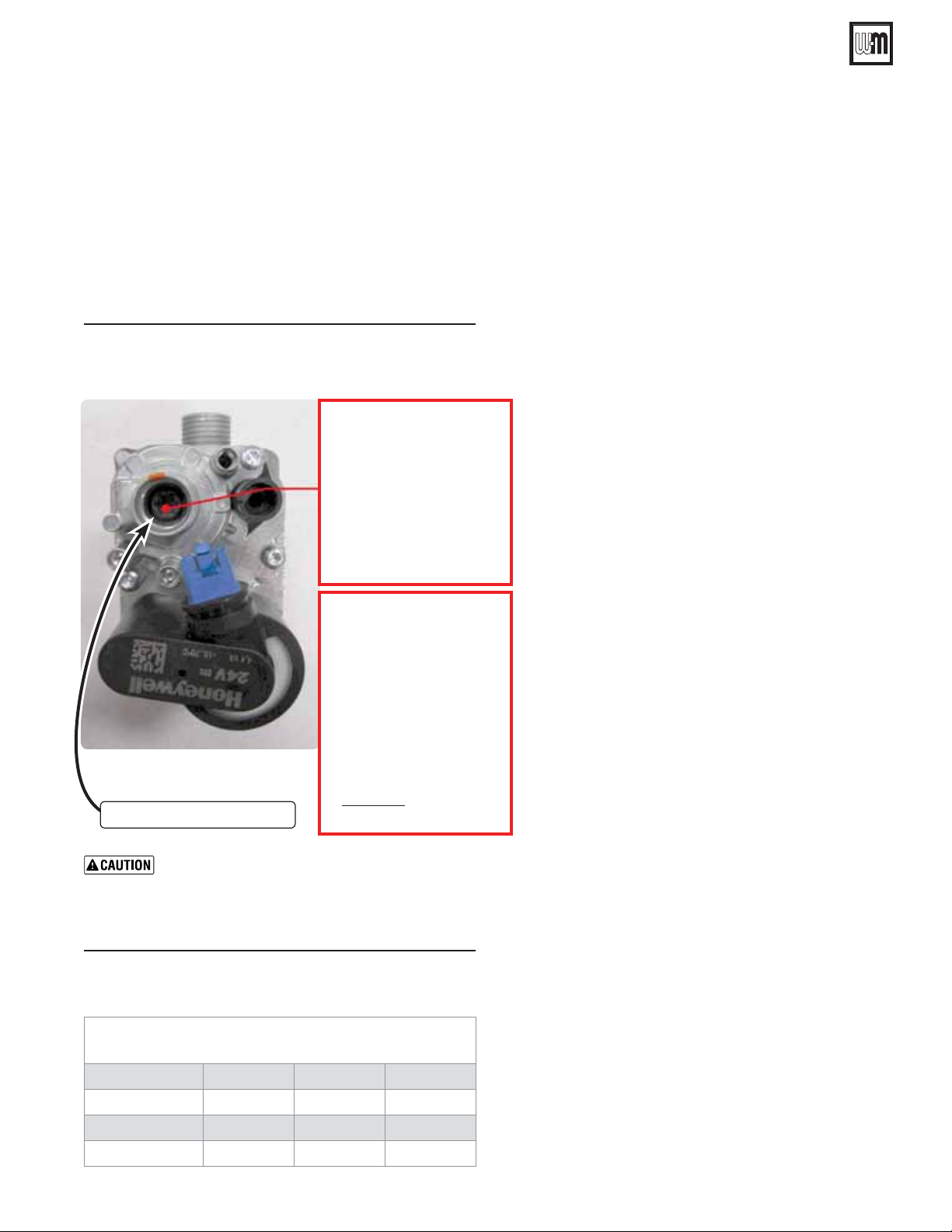
AquaBalance® SERIES 2 WALL MOUNT GAS-FIRED WATER BOILER — Boiler Manual
30 6WDUWXS²¿QDOFKHFNV (continued)
At Minimum Rate:
1. Remove T-40 cap, see Figure 104, page 78, for Offset screw
adjustment. Adjust the boiler to minimum output and allow
the boiler to stabilize.
2. Now adjust the offset pressure setting (Figure 105 - screw B)
Torx (T-40 male driver) until the CO
is at the correct SET-
2
TING LEVEL (see Figure 106), confirm that the CO/CO2
ratio is within limits (clockwise to increase gas).
Figure 105 Offset adjustment screw ––
(ONLY for use by a qualified technician, using
calibrated combustion test instruments).
Offset Regulating screw
Test at MIN. Power 00%
Turn clockwise (open gas)
IRU³0$;JDVÀRZ´
Turn counter-clockwise
(close gas)
IRU³0,1JDVÀRZ´
Rough start point
For LP Start up ONLY
Adjust gas valve
LOW FIRE
screw on left with
Allen wrench
Counter-Clock wise
ǩó turn.
Final Combustion values
MUST BE checked with
Offset adjustment B
Adjust in steps of no more than 1/8 of a turn and
wait 1 minute after each adjustment to allow the
setting to stabilize. Turning the screw too far will
cause the adjustment to reverse behavior.
Figure 106 Minimum rate combustion values –
measured values must be within the ranges
given below
Combustion Analyzer.
turn
Re-check the Maximum and Minimum
Rate
3. After the gas valve is adjusted, please check one more
time that the Maximum and Minimum rate CO/CO2
to ensure that the values have not changed.
4. In the event that the CO
setting level with an acceptable
2
CO/CO2 ratio cannot be obtained please contact your
Weil-McLain Technical Support.
❏ Check Heat exchanger and vent seals
1. Operate the boiler on HIGH fire.
2. A leak would appear as vapor on the surface of the
mirror.
3. If there is any indication of a leak at any joint, immediately shut down the boiler.
a. If possible, tighten the retaining screws or nuts
(without over-tightening).
b. If this does not correct the problem, disassemble
the components where the leak appeared. Use the
procedures given in the Maintenance section of
this manual.
c. When disassembling components, inspect gaskets to
see if there is damage. Replace any damaged gasket.
d. Contact your Weil-McLain Technical Support if the
problem cannot be addressed with the information
provided in this manual.
❏ Check ignition system safety shutoff device
1. After the boiler has been installed, turn off the boiler.
2. Shut off the manual gas valve located on the gas line to
cut flow of fuel to the boiler.
3. Turn on the boiler. It will start to ignite and a “d3” code
will flash. After the “d3” code flash for some time the
boiler will go into a Lockout condition and a “A01” code
will show in the display. It means that the boiler tried to
ignite without success (code “d3”) for three (3) times
and when into Lockout mode(code “A01”). This means
that the ignition system safety device worked properly.
4. Open the manual gas valve located on the gas line to
resume fuel supply to the boiler.
5. Hit the “Reset” button once to Clear the Lockout code
“A01”.
Natural Gas/LP Acceptable Combustion Range
Minimum Rate after 10 minutes from cold
Boiler Model
AB-80
AB-120
AB-155
Part number 550-100-325/0718
CO/(PPM) CO
20 8.0 – 9.0 9.0 – 9.8
20 8.0 – 9.0 9.0 – 9.8
7 8.0 – 9.0 9.0 – 9.8
NG % CO2 LP %
2
79
Page 80
AquaBalance® SERIES 2 WALL MOUNT GAS-FIRED WATER BOILER — Boiler Manual
31 6WDUWXSYHUL¿FDWLRQ
Additional field-installed limit control(s) set to system
Adjust and test boiler controls
1. Follow instructions in this manual to set and verify operation
of the boiler controls.
2. Follow low water cutoff manufacturers instructions
(if used).
Have the following been done?
Boiler and heat distribution units filled with water?
❏
Water chemistry verified per page 71?
❏
Sentinel X100 corrosion inhibitor added and water tested
❏
to be within range?
Air purged from system?
❏
Air purged from gas piping? Piping checked for leaks?
❏
Condensate trap primed?
❏
If boiler has been converted to Liquefied Petroleum (LP) Gas
❏
is propane conversion label affixed to jacket?
Boilers are shipped ready to fire natural gas ONLY.
To fire on propane, you must follow the instructions in this manual to install the propane venturi,
see page 10. Failure to comply could result in severe
personal injury, death or substantial property damage.
Thermostat circuit wiring checked to ensure there are no
❏
stray voltages?
❏
temperature requirements? Balancing valves and controls
adjusted to provide design temperature to system?
Flow adjusted/balanced for each zone of multiple zones
❏
systems?
Thermostat heat anticipator (if available) set properly?
❏
Boiler cycled with thermostats — Raised to highest setting
❏
and verified boiler goes through normal startup cycle? Lowered to lowest setting and verified boiler goes off?
Natural gas input measured? (page 77)
❏
Incoming gas pressure checked by connecting manometer to
❏
gas valve ahead of boiler? (Gas pressure must be at least the
minimum values given on page 14, with boiler operating at
high fire, and no more than 13 inches (330 mm) w.c. with
boiler operating or boiler off.)
Observed several operating cycles for proper operation?
❏
Room thermostats set to desired room temperature?
❏
All instructions shipped with this boiler reviewed with owner
❏
or maintenance person?
Followed Operating Instructions, Figure 101, page 76?
❏
Burner flame and combustion verified per page 77?
❏
Control operation for space heating and DHW (if used)
❏
verified per this manual?
Additional field-installed controls tested as outlined by
❏
control manufacturers? (Boiler should be operating and
should go off when controls are tested. Verify controls cause
automatic reset lockout or manual reset lockout as desired.)
Fill out start-up data on the In-
stallation and Service Certificate,
page 132.
Ignition system safety shutoff device tested?
❏
Before leaving:
Fill in Installation certificate, page 132.
❏
Return instructions to envelope and give to owner.
❏
80
Part number 550-100-325/0718
Page 81
AquaBalance® SERIES 2 WALL MOUNT GAS-FIRED WATER BOILER — Boiler Manual
32 Annual startup and general maintenance
Follow the service and maintenance procedures given throughout this manual and in component literature shipped
with the boiler. Failure to perform the service and maintenance could result in damage to the boiler or system. Failure to
follow the directions in this manual and component literature could result in severe personal injury, death or substantial
property damage.
Figure 107 Service and maintenance schedules
Service technician
(see page numbers indicated for details)
• Handling ceramic fiber materials. . . . . . . . . . . . . . . . . 82
• First-year special inspection . . . . . . . . . . . . . . . . . . . 82
• Address reported problems . . . . . . . . . . . . . . . . . . . 83
• Inspect boiler area . . . . . . . . . . . . . . . . . . . . . . . . 83
• Inspect boiler exterior . . . . . . . . . . . . . . . . . . . . . . 83
• Inspect boiler interior . . . . . . . . . . . . . . . . . . . . . . 83
• Check all piping for leaks . . . . . . . . . . . . . . . . . . . . 83
• Check ignition wiring . . . . . . . . . . . . . . . . . . . . . . . 83
Owner maintenance
(see User’s Information Manual)
• Check boiler area.
• Check air openings.
Daily
Monthly
• Check pressure/
temperature gauge.
• Verify boiler jacket door is
securely in place.
• Check vent piping.
• Check air piping.
• Check condensate drain
system.
• Check for leaks.
• Check all boiler wiring . . . . . . . . . . . . . . . . . . . . . . 83
• Check control settings . . . . . . . . . . . . . . . . . . . . . . 83
• Perform startup and checks . . . . . . . . . . . . . . . . . . . 83
• Check burner flame . . . . . . . . . . . . . . . . . . . . . . . 83
ANNUAL START-UP (See First-year special inspection)
• Check boiler relief valve . . . . . . . . . . . . . . . . . . . . . 84
• Reinstall jacket door after servicing . . . . . . . . . . . . . . . 84
• Review with owner . . . . . . . . . . . . . . . . . . . . . . . . 84
Part number 550-100-325/0718
Every
6 months
• Verify that domestic hot
water is being supplied
to fixtures at the correct
temperature.
• Check boiler piping (gas
and water).
• Operate relief valve.
81
Page 82

AquaBalance® SERIES 2 WALL MOUNT GAS-FIRED WATER BOILER — Boiler Manual
33 Annual startup
HANDLING CERAMIC FIBER
MATERIALS
REMOVING BURNER GASKET or
COVER PLATE INSULATION
The heat exchanger refractory contain
ceramic fiber
identified as carcinogenic, or possibly
carcinogenic, to humans).
can be converted to cristobalite in very
high temperature applications.
The International Agency for Research on
Cancer (IARC) has concluded, “Crystalline silica inhaled in the form of quartz or
cristobalite from occupational sources is
carcinogenic to humans (Group 1).”:
■ Avoid breathing dust and contact with skin and eyes.
• Use NIOSH certified dust respirator (N95).
This type of respirator is based on the OSHA
requirements for cristobalite at the time this
document was written. Other types of respirators may be needed depending on the job site
conditions. Current NIOSH recommendations
can be found on the NIOSH web site at http://
www.cdc.gov/niosh/homepage.html. NIOSH
approved respirators, manufacturers, and phone
numbers are also listed on this web site.
• Wear long-sleeved, loose fitting clothing,
gloves, and eye protection.
■ Handle carefully to minimize dust that could be
caused by abrasion.
■ If replacement is necessary, remove the refractory
from the boiler and place it in a plastic bag for
disposal.
■ Wash potentially contaminated clothes separately
from other clothing. Rinse clothes washer thoroughly.
NIOSH stated First Aid
■ Eye: Irrigate immediately.
■ Breathing: Fresh air.
materials that have been
Ceramic fibers
FIRST-YEAR SPECIAL INSPECTION
1. No later than 12 months after the boiler is installed, per-
form a first-year inspection of the boiler. This should include
the following in addition to routine annual start-up
procedures
a. The integrity of the flue system and the flue seals;
b. The integrity of the boiler combustion circuit and the
relevant seals;
c. The operational (working) gas inlet pressure at
maximum rate, as described on pages 47 and 78;
d. The gas rate, as described on page 47;
e. The combustion performance, as described on pages 77,
78 and 79 for combustion check.
f. Competence to carry out the check of combustion per-
formance.
g. The person carrying out a combustion measurement
should have been assessed as competent in the use of a
flue gas analyzer and the interpretation of the results;
Periodical check
h. To keep the unit working properly over time, it is necessary to
have qualified personnel make an annual check that includes
the following tests:
i. The control and safety devices (gas valve, flow meter,
thermostats, etc.) must function correctly.
j. The flue pipes must be fully intact, secure and clear.
k. The airtight chamber must be sealed.
l. The air-flue terminal and ducts must be free of obstructions
and leaks.
m. The condensate evacuation system must be efficient with no
leakage or obstructions and drain condensate without back-
ing up.
n. The burner and heat exchanger must be clean and free of scale.
When cleaning, do not use chemical products or wire brushes.
o. The electrode must be free of scale and properly positioned.
p. The gas and water systems must be leak free.
q. The water pressure in the heating system must be minimum of
12 PSI, do not exceed 25 PSI. Fill the boiler to that pressure or
the system design pressure.
r. The circulation pump must not be blocked.
s. The expansion tank must be filled.
t. The gas flow and pressure must correspond to that given in the
respective tables.
2. Determine any follow-up maintenance and service needs based on
the condition of the heat exchanger and condensate lines.
a. If the heat exchanger shows substantial fouling, or if condensate
lines show accumulation of sediment, schedule a follow-up
service call to perform the first-year inspection again, sooner
than the normal twelve months between.
b. Heavy fouling of the heat exchanger or condensate lines indi-
cates possible combustion air contamination. Inspect the air
intake area carefully, and remove possible contaminants. See
page 6, for products to avoid.
.
You must eliminate causes of corrosion and con-
tamination to ensure reliable operation of the boiler
and system.
82
Part number 550-100-325/0718
Page 83
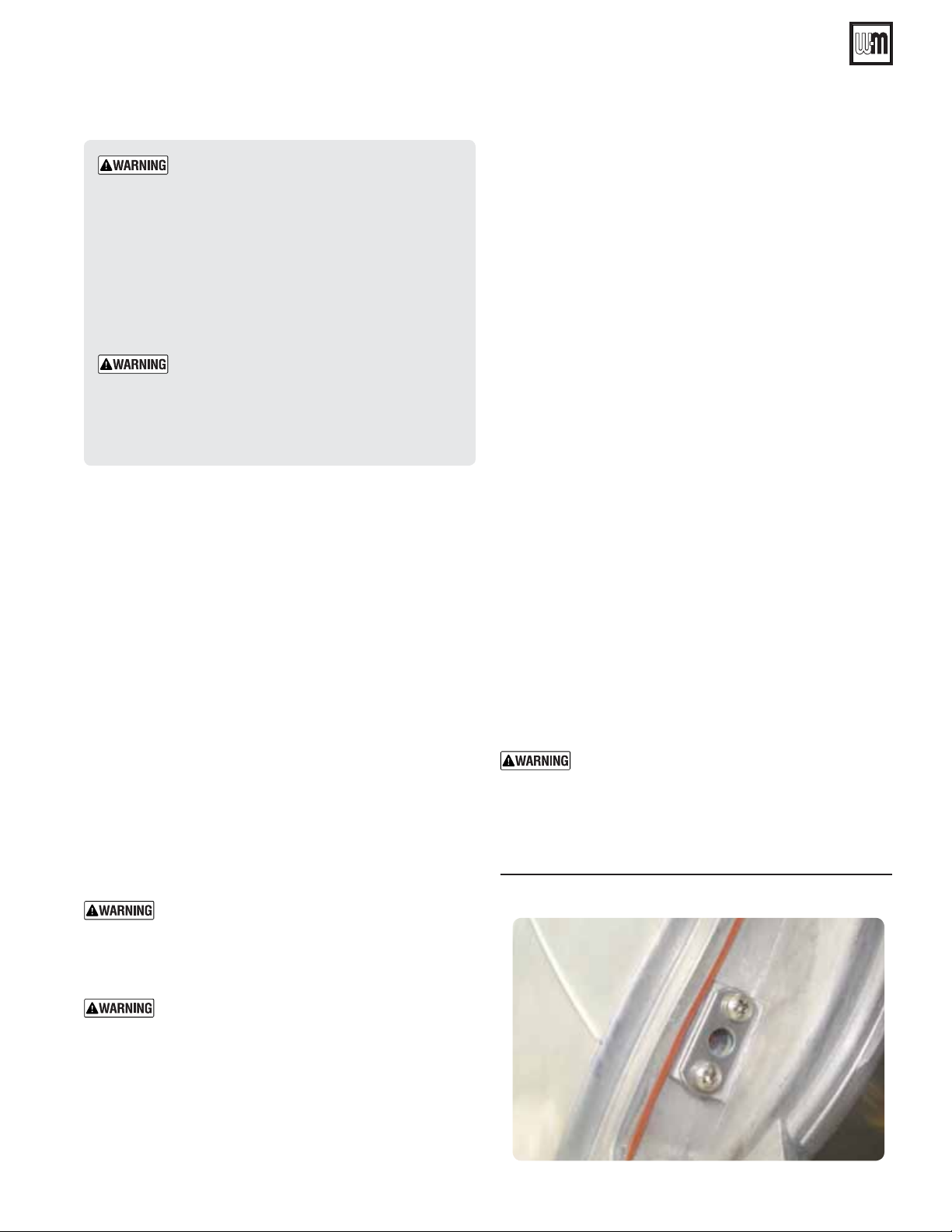
AquaBalance® SERIES 2 WALL MOUNT GAS-FIRED WATER BOILER — Boiler Manual
33 Annual startup (continued)
The boiler should be inspected and started
annually, at the beginning of the heating
season, only by a qualified service technician.
In addition, the maintenance and care of the
boiler designated in Figure 107, page 81 and
explained on the following pages must be performed to assure maximum boiler efficiency
and reliability. Failure to service and maintain
the boiler and system could result in equipment failure.
Electrical shock hazard — Turn off power to
the boiler before any service operation on the
boiler except as noted otherwise in this instruction manual. Failure to turn off electrical
power could result in electrical shock, causing
severe personal injury or death.
Address reported problems
1. Inspect any problems reported by owner and correct before
proceeding.
Inspect boiler area
1. Verify that boiler area is free of any combustible materials,
gasoline and other flammable vapors and liquids.
2. Verify that air intake area is free of any of the contaminants
listed on page 6 of this manual. If any of these are present in the
boiler intake air vicinity, they must be removed. If they cannot
be removed, reinstall the air and vent lines per this manual.
Check ignition wiring
1. Check ignition cable electrical resistance. A good cable will
have resistance between 950 and 1050 ohms. Replace if not
acceptable.
2. Inspect boiler ground wire from heat exchanger access cover
to ground terminal screw.
3. Verify all wiring is in good condition and securely attached.
4. Check ground continuity of wiring using continuity meter.
5. Replace ground wires if results are not satisfactory.
Check all boiler wiring
1. Inspect all boiler wiring, making sure wires are in good condition and securely attached.
2. Verify that all connectors are securely inserted.
Check control settings
1. Use the control display to navigate through all settings. Adjust
settings if necessary.
2. Check settings of external limit controls (if any) and adjust
if necessary. Adjust as needed to accommodate the system
design.
Perform startup and checks
1. Start boiler and perform checks and tests specified in this
manual.
2. Verify cold fill pressure is correct and that operating pressure
does not go too high. Adjust water pressure and expansion
tank charge pressure as necessary.
3. Complete the check-out procedure on page 80.
Inspect boiler exterior
1. The boiler door, panels and aesthetic parts can be cleaned
with a soft damp cloth, possibly soaked in soapy water. Do
not use any abrasive detergents and solvents.
Inspect boiler interior
1. Remove jacket door and inspect interior of boiler.
2. Vacuum any sediment from the inside of the boiler and
components. Remove any obstructions.
Do not use solvents to clean any of the boiler
components. The components could be damaged,
resulting in unreliable or unsafe operation.
Check all piping for leaks
Eliminate all system or boiler leaks. Continual fresh
make-up water will reduce boiler life. Minerals
can build up in the heat exchanger, reducing heat
transfer, overheating heat exchanger, and causing
heat exchanger failure. Leaking water may also
cause severe property damage.
1. Inspect all water and gas piping and verify to be leak free.
2. Look for signs of leaking lines in the system and in the boiler
and correct any problems found.
3. Check gas line for leaks, see page 76 for gas safety information.
Check burner flame
The boiler contains ceramic fiber materials. Use
care when handling these materials per instructions
on page 82 of this manual. Failure to comply could
result in severe personal injury.
1. Inspect flame through observation window.
Figure 108 Observation window
Part number 550-100-325/0718
83
Page 84

AquaBalance® SERIES 2 WALL MOUNT GAS-FIRED WATER BOILER — Boiler Manual
33 Annual startup (continued)
2. If flame is unsatisfactory at either high fire or low fire,
check combustion values. If combustion is properly
adjusted, turn off boiler and allow boiler to cool down.
Then remove burner and clean it thoroughly using a vacuum cleaner or compressed air. Do not use compressed
air to clean burner if performed inside a building.
3. To access the burner, remove the heat exchanger cover
plate following the procedure beginning on page 108.
Check boiler relief valve
1. Inspect the relief valve and lift the lever to verify flow as in the
following warnings, excerpted from a relief valve manufacturer’s warning label. Before operating any relief valve, ensure
that it is piped with its discharge in a safe area to avoid severe
scald potential.
4. If replacing the burner, ensure the burner gasket is in
good condition and correctly positioned. Follow all
instructions on page 109 to reinstall all components.
5. Restart the boiler.
6. Inspect the flame at high and low fire. If flame is still
not acceptable, check combustion values. If combustion
is properly adjusted, obtain a replacement burner from
Weil-McLain.
Check automatic air vents (if used
— automatic air vents must be used with
diaghragm-type expansion tanks only)
see page 35.
Reinstall jacket door after
servicing
Reinstall boiler jacket door after start-up or servicing.
The boiler jacket door must be securely fastened to the
boiler to prevent boiler from drawing air from inside
the boiler room. This is particularly important if the
boiler is located in the same room as other appliances.
Failure to keep the jacket door securely sealed and
fastened could result in severe personal injury or death.
Review with owner
1. Review the User’s Information Manual with the
owner.
2. Emphasize the need to perform the maintenance
schedule specified in the User’s Information Manual
(and in this manual as well).
2. Read page 38 before proceeding further.
3. Follow instructions below or perform procedures per relief
valve manufacturer’s printed instructions.
Safety relief valves should be reinspected AT LEAST
ONCE EVERY THREE YEARS, by a licensed plumbing contractor or authorized inspection agency, to
ensure that the product has not been affected by corrosive water conditions and to ensure that the valve
and discharge line have not been altered or tampered
with illegally. Certain naturally occurring conditions
may corrode the valve or its components over time,
rendering the valve inoperative. Such conditions are
not detectable unless the valve and its components
are physically removed and inspected. This inspection must only be conducted by a plumbing contractor or authorized inspection agency — not by
the owner. Failure to reinspect the boiler relief valve
as directed could result in unsafe pressure buildup,
which can result in severe personal injury, death or
substantial property damage.
Following installation, the valve lever must be
operated AT LEAST ONCE A YEAR to ensure that
waterways are clear. Certain naturally occurring
mineral deposits may adhere to the valve, rendering
it inoperative. When manually operating the lever,
water will discharge and precautions must be taken
to avoid contact with hot water and to avoid water
damage. Before operating lever, check to see that a
discharge line is connected to this valve directing
the flow of hot water from the valve to a proper
place of disposal. Otherwise severe personal injury
or property damage may result. If no water flows,
valve is inoperative. Shut down boiler until a new
relief valve has been installed.
3. Remind the owner of the need to call a licensed
contractor should the boiler or system exhibit any
unusual behavior.
4. Remind the owner to follow the proper shutdown
procedure and to schedule an annual startup at the
beginning of the next heating season.
84
4. After following the above warning directions, if the relief
valve weeps or will not seat properly, replace the relief valve.
Ensure that the reason for relief valve weeping is the valve and
not over-pressurization of the system due to expansion tank
waterlogging or under-sizing.
Part number 550-100-325/0718
Page 85
V
G
VERIFY PROPER OPERATION AFTER SERVICING
AquaBalance® SERIES 2 WALL MOUNT GAS-FIRED WATER BOILER — Boiler Manual
—
34 Troubleshooting
ERIFY PROPER OPERATION AFTER SERVICIN
Before calling for troubleshooting assistance, fill in the
“
Boiler Startup Data Collection Sheet” (page 132).
Record the boiler size and CP number (located on the
left side exterior of the boiler jacket).
Failure to adhere to these guide-
lines can result in severe personal injury, death or substantial
property damage.
ELECTRICAL SHOCK HAZARD
TURN OFF ALL POWER TO THE BOILER WHEN
SERVICING
the switch is off.
. Internal wiring is still powered when
DO NOT JUMPER DEVICES
Never jumper (bypass) any device except for momentary testing.
REINSTALL Jacket door
The boiler jacket door must be securely fastened to
the boiler to prevent boiler from drawing air from
inside the boiler room. This is particularly important
if the boiler is located in the same room as other appliances. Failure to keep the jacket door securely fastened could result in severe personal injury or death.
BEFORE SERVICING or
MAKING CONNECTIONS —
EFORE TROUBLESHOOTING
1. Check for 120VAC (minimum 102 VAC to maximum 132 VAC)
to boiler.
2. Check the control for error codes.
3. See Figure 76, page 58 for navigation instructions and the pages
following for the display key identification.
Hold reset button for 20 seconds:
• TS Flashing (parameter)
• Push heating – button
• IN flashing (information)
• Push heating – button
• HI flashing (history/fault)
• Push “Reset” once
• Push + to scroll error codes, refer to error code list Table 3,
page 88.
To exit out, hold reset button for 20 seconds.
Figure 109 Tools and kits needed for troubleshooting.
Tool Purpose
#2 Phillips screwdriver
10mm wrench
#20 long-handled Torx
driver
T-40 Torx driver
4mm Allen wrench
Multimeter
Manometer
(Inclined or digital)
Combustion analyzer
(Digital preferred)
Contact thermometer
Multiple uses
Remove heat exchanger cover plate
Remove burner screws
For gas valve Offset Lowfire adjustment
For gas valve Highfire adjustment
Measurements on sensors and electrical components
Measures the INLET gas pressure to the boiler
Combustion testing and boiler adjustments
Checking surface temperatures of heat exchanger and
pipes
ALWAYS TURN POWER OFF TO THE BOILER
TO PREVENT ELECTRICAL SURGES, WHICH
CAN DAMAGE BOILER COMPONENTS.
LABEL WIRES BEFORE
REMOVING
Label all wires prior to disconnection
when servicing controls. Wiring errors
can cause improper and dangerous
operation.
Part number 550-100-325/0718
Check the following:
1. Make sure thermostat is calling for heat and contacts (including
appropriate zone controls) are closed. Make sure all external limit
controls are either installed (and closed) or temporarily jumpered
for testing.
2. Make sure that connectors to control are securely plugged in at
module and originating control.
3. Gas pressures:
• Maximum: 13” w.c. with no flow (gas valve lockup pressure).
• Minimum: 3.5” w.c. minimum values given on page 14 while
operating on high fire.
85
Page 86
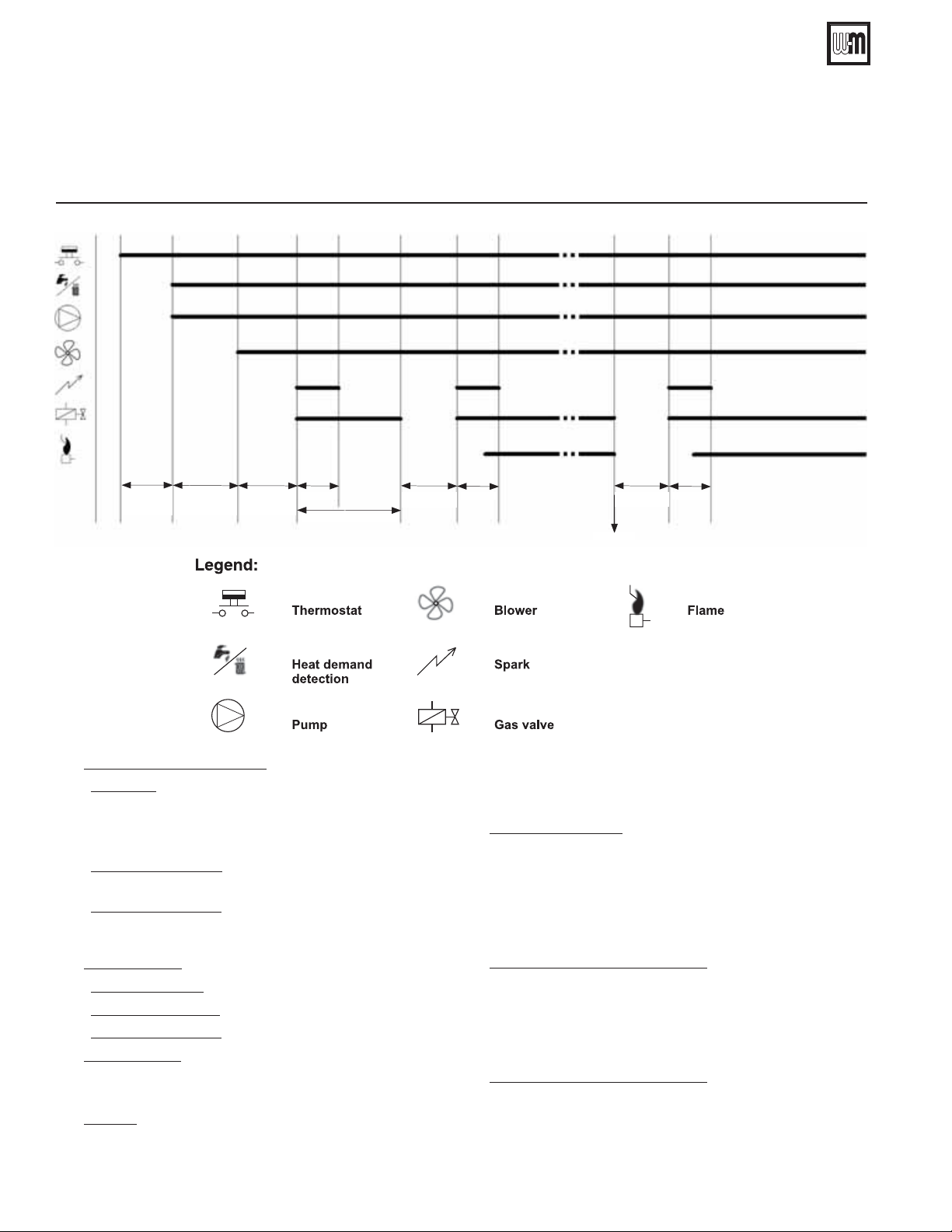
AquaBalance® SERIES 2 WALL MOUNT GAS-FIRED WATER BOILER — Boiler Manual
34 Troubleshooting (continued)
Check ignition sequence
The ignition sequence time line and operational description for the Combi and Heating Only boilers below help to understand the
timing of the cycles. In your troubleshooting, refer to the numbers 1 through 7 as they describe each step of the ignition cycle.
Figure 110 Time line of ignition sequence for the Combi and Heating Only boilers.
HEAT DEMAND
DETECTION TIME
PRE-PUMP TIME PRE-PURGE TIME
IGNITION
GAS VALVE SAFETY TIME
1. Heat demand detection time
CH mode: there is a confirming time of 3 seconds during
which the demand has to be always on.
The request switch is sampled every 0.2 seconds, so the
maximum delay is 3.2 seconds.
DHW instant mode: Combi boiler the maximum delay
is 0.2 seconds which is the sample time of the flow sensor.
DHW storage mode: Heating Only boiler with Indirect
tank the maximum delay is 0.2 seconds which is the
sample time of the tank thermostat.
2. Pre-pump time
CH instant mode: CH - Pump time 30 seconds.
DHW instant mode: there is no pre-pump.
DHW storage mode: DHW Pre-pump time 30 seconds.
3. Pre-purge time
It is the time that the fan takes to reach the ignition level
to effectively purge boiler venting.
4. Ignition
There are 0.2 seconds of preignition where the control
checks the status of the gas valve. And then there is the
INTER-PURGE FOR
A01 ATTEMPTS
IGNITION
INTER-PURGE FOR
FLAME LOSS
A06 ATTEMPTS
IGNITION
spark, for a time depends on the gas type:
Natural Gas, 1.6 seconds.
LP Gas, 4.6 seconds.
5. Gas valve safety time
With no flame the gas valve can be kept open for certain time:
Natural Gas, 3 seconds.
LP Gas, 4.8 seconds.
If at the end of this time the flame is not ionized, the gas
valve has to be closed and the inter-purge time for 6 attempts is ran.
6. Inter-purge time for A01 attempts
There is 10 seconds of purge time before a new attempt
after a faulty ignition. After 5 attempts the boiler goes into
Lockout (code “A01”). This error condition is stopping
the boiler and to get to normal operation again, manual
reset is required.
7. Inter-purge time for A06 attempts
There is 1 second of purge time before a new attempt after
a lost flame. If the flame disappeared 3 consecutive times
within 10 minutes, the boiler goes into Lockout (code
“A06”) to get to normal operation again, manual reset is
required.
86
Part number 550-100-325/0718
Page 87
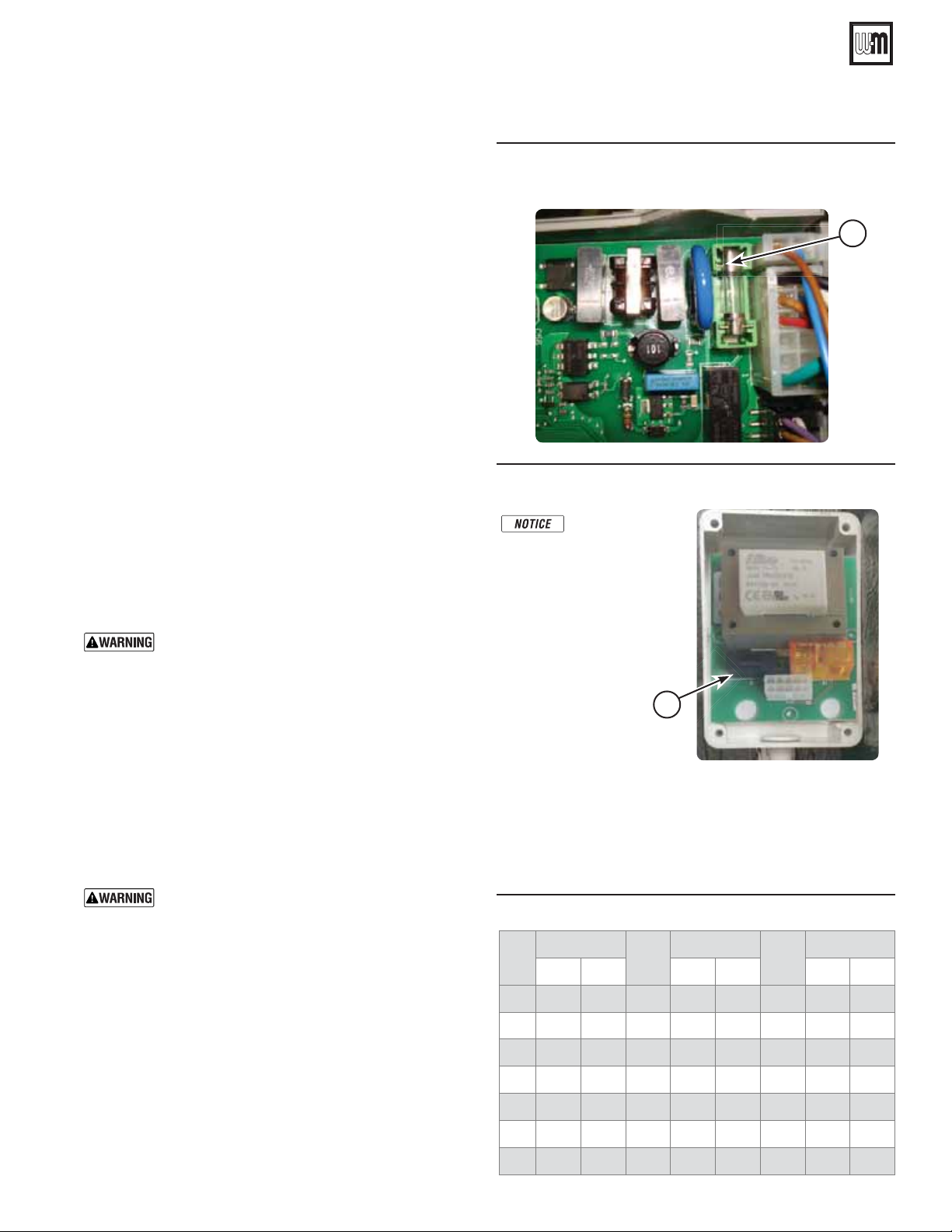
AquaBalance® SERIES 2 WALL MOUNT GAS-FIRED WATER BOILER — Boiler Manual
34 Troubleshooting (continued)
Check flame signal
1. Navigate to Diagnostics/Inputs on the control display (see
pages 58 to 62 for navigation instructions.
2. The flame signal value must be at least 25 on low fire. The
flame signal value must be at least 255 on high fire, reading
at times 10 equals microamps of flame signal. If the flame
signal drops below this level, the control will attempt to correct by increasing the blower speed to increase flame signal.
3. A low flame signal may indicate a fouled ignitor or damaged
ignitor cable insulation.
a. See “Inspect ignition electrode,” page 107 to remove
and inspect the ignitor.
b. If required, clean the ignitor and flame rod as in-
structed, see page 107.
c. If cleaning the ignitor does not improve, ground wiring
is in good condition, and ground continuity is satisfactory, replace the ignitor.
4. If flame signal still remains low:
a. Inspect the vent and air piping.
b. Check combustion values.
c. Then inspect the heat exchanger, following the proce-
dures given in this manual for inspecting and cleaning of the heat exchanger cover plate and other boiler
components (starting on page 107).
d. Clean the heat exchanger as described in this manual if
necessary, see page 110.
Check control fuse
ALWAYS check circuit fuses before replacing
control or any major components (blower,
etc.). If a fuse is blown, it can prevent the control or other components from operating.
1. Turn OFF power to boiler at external line switch. Then
remove the jacket door.
2. Locate fuses using Figure 111 and Figure 112.
3. Remove and inspect the fuses (Item a, Figure 111 or Item
b, Figure 112).
4. If necessary, replace the fuses:
a. Control circuit fuse is a 250 VAC 3.15-amp rated
fuse. (Littelfuse 326012P)
b. Thermostat-relay circuit fuse is a 250 Volt 630mA rated
fuse. (Littelfuse 071-852 Type 5 x 20mm).
Do not jumper fuses or replace with any fuse
except as specified. Failure to comply could result
in severe personal injury, death or substantial
property damage.
Checking temperature sensors
1. The boiler temperature sensors (flue, outdoor, return
water and supply water) are all resistance-type devices.
Figure 113 shows the correct value for the sensor at various
temperatures. For dual sensors, the temperature difference
between the sensors must be no more than 10 °F. (Supply
outlet 200 sensor).
2. Use the resistance values at 32°F, 60°F, 70°F and 212°F to
measure the sensor resistance at known temperatures (ice
point, room temperature and sea level boiling point). For
ice point and boiling point, insert the sensor in water at
that temperature. Use an ohmmeter to read resistance value.
Figure 111 Control circuit fuse location
Fuse located on rear of circuit board
Figure 112 Thermostat-relay circuit fuse location
Installer/homeowner note,
in case of an “open circuit”
of the Thermostat-relay
fuse the boiler can run in
DHW mode but NOT in
Central Heating mode.
b
3. To check whether the control is correctly sensing temperature,
you can use a resistance decade box. Connect the decade box
temporarily in place of a sensor and read the corresponding
temperature on the control display. The temperature should
be close to the value corresponding to the input resistance.
Figure 113 Sensor resistances values
Temp
Sensor ohms
(°F)
Min Max Min Max Min Max
32
31530 33480
40
25792 27388
50
19258 20450
60
15218 16160
70
11577 12293
80
8891 9441
90
7185 7629
Temp
(°F)
100
110
120
130
140
150
160
Sensor ohms
5608 5954
4590 4874
3636 3860
3011 3197
2417 2567
1954 2074
1644 1746
Temp
(°F)
170
180
190
200
212
-
-
a
Sensor ohms
1344 1428
1143 1213
945 1003
810 860
657 697
--
--
Part number 550-100-325/0718
87
Page 88
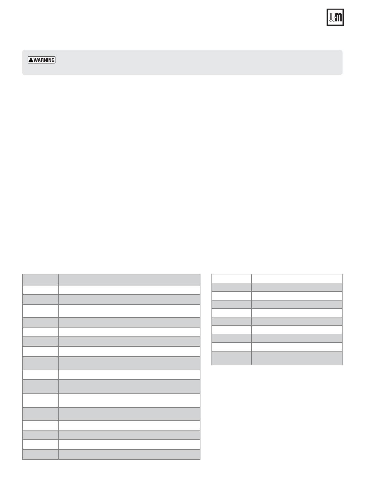
AquaBalance® SERIES 2 WALL MOUNT GAS-FIRED WATER BOILER — Boiler Manual
34 Troubleshooting (continued)
Make sure to determine the causes of outages. Do not leave the boiler operating without a com-
plete diagnosis.
Control diagnosis
1. The boiler control is equipped with an advanced self-diagnosis system. In case of a boiler fault, the display will flash together with
the fault symbol (see Table 3 or Table 4) indicating the fault code.
2. Certain faults cause permanent boiler shutdowns (marked with the letter “A” see Table 3): to restore operation, press the RESET
button (Item 6 - Figure 76, page 58) for 1 second or RESET on the optional remote timer control if installed; if the boiler fails
to start, it is necessary to firstly eliminate the fault.
3. Other faults (indicated with the letter “F”, see Table 4, page 91) cause temporary shutdowns that are automatically reset as soon
as the value returns within the boiler’s normal operating range.
Protection and error conditions
1. Several checks are included to protect the boiler and its environment. Severe error will cause a lockout condition which can only
be cleared by the reset key at the boiler front panel.
2. Non severe errors faults will reset as soon as the cause of the problem disappears/corrects themselves.
3. Number of reset action is limited to 5 in 24 hours. By powering off/on, it is possible to reset this limitation: in this way, another
5 reset per 24 hour can be done.
4. Error codes can be divided in 2 groups:
a. Manual Reset type lockout codes – “A” codes: (which blocks the heat demand - Press reset button for 1 second to reset)
b. Automatic Reset type lockout codes – “F” codes: (cause temporary shutdowns that are automatically reset as soon as the
value returns within the boilers normal working range)
Hard Lock-out condition codes
Lock out condition is given with the capital “A” (alarm) on the status display and error code on the
temperature display. The meaning of the error numbers are as follow:
Table 3 “A” codes – Hard Lock-out – Manual Reset
Error code Description
A01 1REXUQHULJQLWLRQDIWHU¿YHDWWHPSWV
A02 )DOVHÀDPHLQGLFDWLRQ
A03
A04 F07 repeated 3 times in the last 24 hours
A05 No frequency feedback from fan after 1 hour
A06 WLPHVÀDPHORVVLQPLQXWHVWLPHIUDPH
A16 Outside sensor is not connected
A23
A26 F40 repeated 3 times in the last hour
A41
A42
A44
A61 Flame circuit error
A62 Gas valve circuit
A63 E2 prom error
A65 ADC circuit error
High limit protection: pump does not run or no
water circulation
Nominal water pressure not reached within
maximum allowed time
Temperature sensor not or bad connected to
the pipe (CH mode)
Too high difference between two CH supply water
temperature sensors
Temperature sensor not or bad connected to
the pipe (DHW mode)
Abbreviation Description
ADC Analog Digital Converter
CH Central Heating
DHW Domestic Hot Water
LP /LTXH¿HG3HWUROHXP3URSDQH*DV
LWCO Low Water Cut Off
MMI Machine Interface- Control Interface
OTC Outdoor Temperature Sensor
PCB Printed Circuit Board - Control board
PWM
Pulse width modulation - Used for
modulating pumps and motors
88
Part number 550-100-325/0718
Page 89
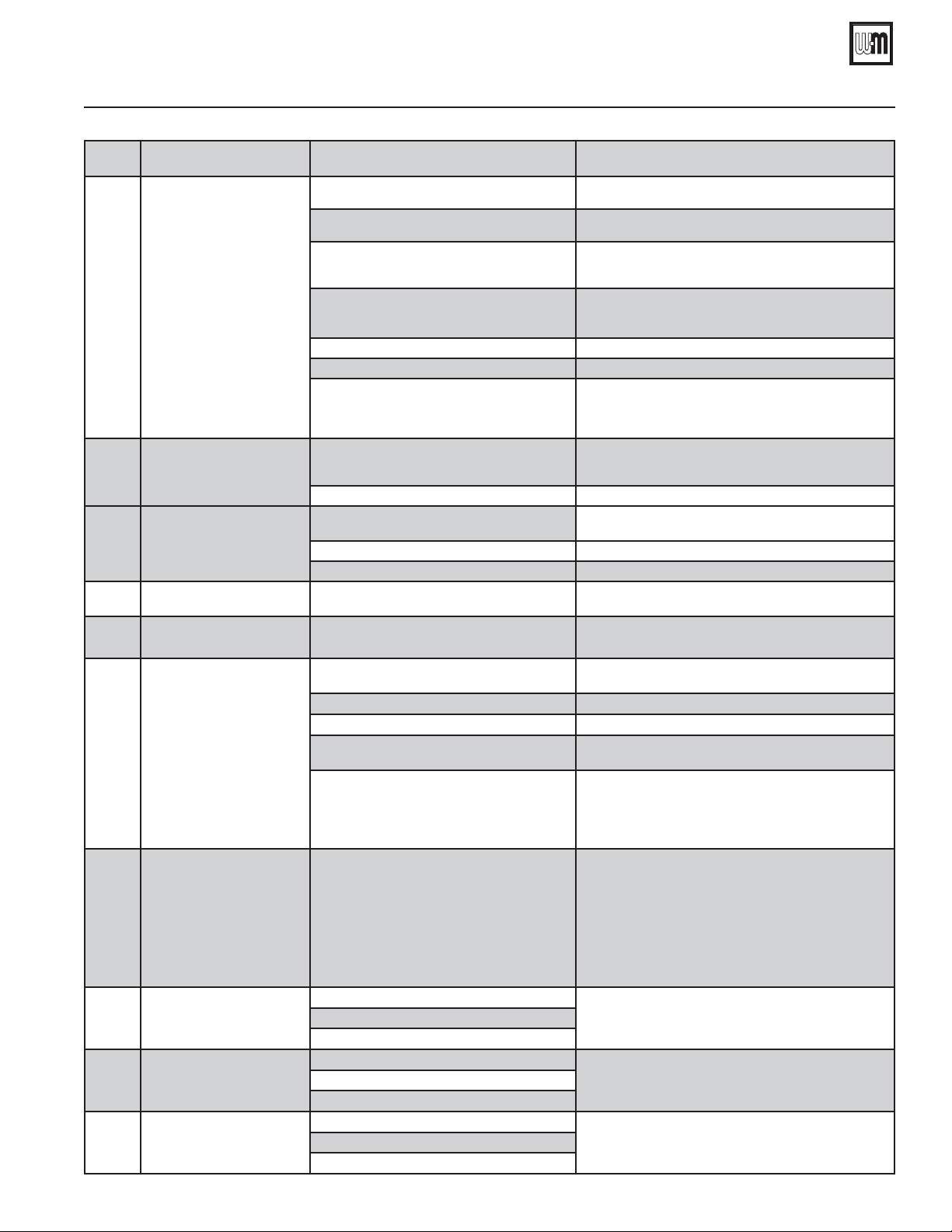
AquaBalance® SERIES 2 WALL MOUNT GAS-FIRED WATER BOILER — Boiler Manual
34 Troubleshooting (continued)
Figure 114 Troubleshooting suggestions — Fault displays and diagnostics (continued)
Fault
Code
A01
A02
A03
A04
A05
A06
F07
F10
F11
F12
Fault Condition Correction
No burner ignition
Flame present signal
with burner off
Over temperature protection activation
Exhaust duct safety
device activation
Fan protection activated
1RÀDPHDIWHULJQLtion stage (6 times in 4
minutes)
High exhaust temperature
Air trapped in boiler heat
exchanger
Combustion not correct
for Natural gas and LP
fuel
Boiler water piping and
circulator not providing
FRUUHFWZDWHUÀRZ
Supply sensor 1 fault
Return sensor fault
DHW sensor fault
No gas
Ignition/detection electrode fault
Electrode fault
Combustion incorrect
Natural gas & LP fuel
Faulty gas valve Check the gas valve and replace it if necessary
,QVXI¿FLHQWJDVVXSSO\SUHVVXUH Check the gas supply pressure
Condensate trap blocked and or condensate drain hose looped making a
second trap
Electrode fault
Ignition cable fault Check the ignition cable
Heating sensor damaged
No water circulation in the system Check the circulating pump
Air in the system/heat exchanger Vent the system/purge heat exchanger
Fault F07 generated 3 times in the last
24 hours
Fault F15 generated for 1 hour (consecutive)
Ignitor electrode fault
Flame unstable Check the burner
Gas valve Offset fault Check the Offset adjustment at minimum power
Air/fume ducts obstructed
Condensate trap blocked
The exhaust probe detects an excessive
temperature
Sensor damaged
Wiring disconnected
Sensor damaged
Wiring disconnected
Sensor damaged
Wiring disconnected
&KHFNWKHUHJXODUJDVÀRZWRWKHERLOHUDQGWKDW
the air has been eliminated from the pipes.
Check the wiring of the electrode and that it is
correctly positioned and free of any deposits
Check the ignitor electrode wiring
Electrode deformed/misaligned and/or improper
gap (5/32”)
Perform combustion test for Natural gas & LP
fuel per chart section Figure 103, page 78 and
Figure 106, page 79.
Check the trap and clean it if necessary
Also inspect gas valve, blower, venturi, igniter,
and heat exchanger, and replace those with
signs of damage.
Check the ignitor electrode wiring
Electrode deformed/misaligned and/or improper
gap (5/32”)
Check the correct positioning and operation of
the heating sensor
See fault F07
See fault F15
Check the position of the ignitor electrode and
replace it if necessary
5HPRYHWKHREVWUXFWLRQIURPWKHÀXHH[KDXVW
ducts and air inlet and terminals
Check the trap and clean it if necessary
Also inspect gas valve, blower, venturi, igniter,
and heat exchanger, and replace those with
signs of damage.
Check the exchanger
Purge out air in heat exchanger
&KHFNFRPEXVWLRQSHUVSHFL¿FDWLRQFKDUWV
Figure 103, page 78 and Figure 106, page 79.
Check piping sizes and required pump models
Check the wiring or replace the sensorWiring shorted
Check the wiring or replace the sensorWiring shorted
Check the wiring or replace the sensorWiring shorted
Part number 550-100-325/0718
89
Page 90
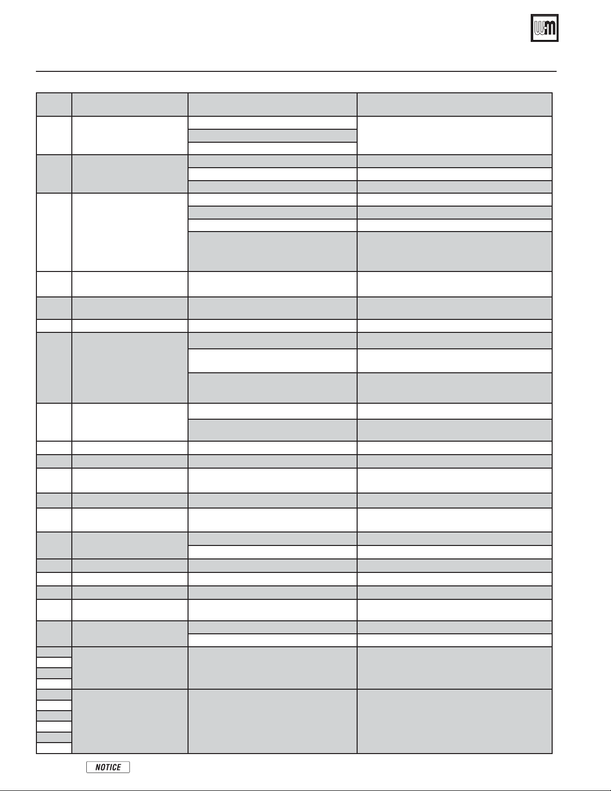
AquaBalance® SERIES 2 WALL MOUNT GAS-FIRED WATER BOILER — Boiler Manual
34 Troubleshooting (continued)
Figure 115 Troubleshooting suggestions — Fault displays and diagnostics (continued)
Fault
Code
F13
F14
F15
F27
F34
F35
F37
F39
A16
A26
A41
A42
A44
F43
F51
F52
F53
A61
A62
A63
F64
A65
F66
A23
A24
F20
F21
F40
F47
Fault Condition Correction
Exhaust probe fault
Delivery sensor 2 fault
Fan fault
Flue temp
Supply voltage under 100V
Faulty voltage frequency
Incorrect system water
pressure
Outdoor sensor fault
Outdoor sensor fault
System installation
Sensor positioning
Heating sensor fault
Temp sensor
Exchanger protection activation.
Low water
Heating sensor fault
Temp sensor
Controller ABM08A fault
No communication between
controller and gas valve
Controller ABM08A fault Controller ABM08A internal error
Card parameter fault Wrong card parameter setting
Probe damaged
Wiring shorted
Wiring disconnected
Sensor damaged Check the wiring or replace the sensor
Wiring shorted
Wiring disconnected
No 120V power supply Check the 8-pin connector wiring
Tachometric signal interrupted Check the 8-pin connector wiring
Fan damaged Check the fan
Condensate trap blocked and or condensate drain hose looped making a
second trap.
Exhaust gas temp too high
Electric voltage trouble
Electric voltage trouble Check the electrical system
Pressure too low < 8 psi
*
Water pressure switch damaged or not
connected
Check Heating Only boiler primary loop
pump, must pump towards return side
of boiler.
Sensor damaged or wiring shorted Check the wiring or replace the sensor
Sensor disconnected after activating the
sliding temperature
Outdoor sensor is not connected Check the sensor
F40 Error repeated 3 times in 1 hour Check the water pressure in the system
Supply sensor disconnected from pipe
Sensor damaged Replace the sensor
Temp sensor not connected or
badly connected to pipe (DHW mode)
No system H2O circulation Check the circulating pump
Air in the system Vent the system
Low water fault Check boiler installation and water level
Sensor damaged Replace the sensor
High limit thermostat error Check the sensor. Check boiler installation
Controller ABM08 internal error
Controller not connected Connect the controller to the gas valve
Valve damaged Replace the valve
Check the wiring or replace the exhaust
probe
Check the trap and clean it if necessary
Also inspect gas valve, blower, venturi, igniter,
and heat exchanger, and replace those with
signs of damage.
Make sure correct vent material was
selected (Parameter List 165)
Check the electrical system (Can’t have
more than 1 pump wired to boiler
Fill the system
Check the sensor
Check pump location and pump water direc
tion
Reconnect the outdoor sensor or disable the
sliding temperature
Check the correct positioning and operation
of the heating sensor
Check the sensor
Check the ground connection and replace the
controller if necessary.
Check the ground connection and replace
the controller if necessary.
Check the card parameter and modify it if
necessary.
-
90
*
Boiler water pressure switch is set for 9 psi (±2) minimum pressure.
Part number 550-100-325/0718
Page 91
AquaBalance® SERIES 2 WALL MOUNT GAS-FIRED WATER BOILER — Boiler Manual
34 Troubleshooting (continued)
Figure 116 Troubleshooting suggestions — Fault displays and diagnostics (continued)
Blocking codes
The boiler controller recognizes also the fault situations that can block the heat demands but do not lead to lockout condition.
When the error condition becomes resolved, error will disappear but will be also written into the history data. If this is the case,
there is also an “F” on the status display. Temperature display gives an error code. The meaning of the code is as follow:
Table 4 “F” codes – Soft Lock-out – Automatic Reset
Error code Description
F07
F10
F11
F12
F13
F14
F15
F20
F21
F27
F34
F35
F37
F39
F40
F43
F47
The Exhaust gases temperature is too high.
The CH supply water temperature sensor 1 error.
The CH return water temperature sensor error.
The DHW water temperature sensor error.
The Exhaust gases temperature sensor error.
The CH supply water temperature sensor 2 error.
Minimum and maximum frequency feedback from fan error.
The water pressure in the CH installation is near the low level.
The water pressure in the CH installation is near the high level.
The exhaust gas temperature is too high (PVC/CPVC/Polypro/AL29-4C - selection).
Low mains voltage.
Frequency error.
The water pressure in the CH installation is too low.
Outside sensor error.
The water pressure in the CH installation is too high or there’s a Control fault.
Heat exchanger protection.
Water pressure sensor not connected.
F50
F51
F52
F53
F64
F66
Part number 550-100-325/0718
Variable input switch contact opened.
Low water error.
Too high difference between two CH supply water temperature sensors.
High limit thermostat input error.
5 MicroCom reset in 15 minutes time frame.
Software doesn’t match.
91
Page 92
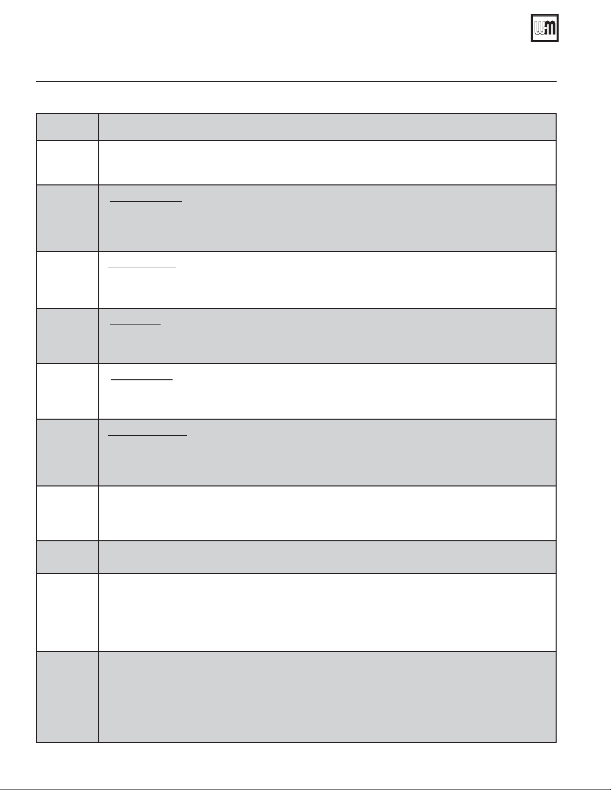
AquaBalance® SERIES 2 WALL MOUNT GAS-FIRED WATER BOILER — Boiler Manual
34 Troubleshooting (continued)
Figure 117 Troubleshooting suggestions — Fault displays and diagnostics (continued)
Display Condition
FAULT 07 =
FAULT 10 =
FAULT 11 =
FAULT 12 =
FAULT 13 =
FAULT 14 =
If the exhaust gases temperature becomes higher than Maximum exhaust gases temperature and the high temperature is present longer than 5 seconds, controller will stop indicating fault 7, where he will stay for 15 minute.
If the exhaust temperature is within normal levels after this time expired, error 7 will be resolved by itself.
CH supply sensor 1 (Supply Temp sensor) out of normal operating range (short circuit or open circuit). If sensor
goes outside the range, error will be generated. In case sensor is back to the normal operating range, error is
gone. In error mode, heat demands will be disabled. In case 2 or more sensors are broken, controller will pick
XSWKH¿UVWWKDWZDVRXWVLGHWKHRSHUDWLQJUDQJH5HVROYLQJVLWXDWLRQFDQEHDFKLHYHGRQO\LIWKHVHQVRULVZLWKLQ
operating range again.
CH return sensor out of normal operating range (short circuit or open circuit). If sensor goes outside the range,
error will be generated. In case sensor is back to the normal operating range, error is gone. In error mode, heat
GHPDQGVZLOOEHGLVDEOHG,QFDVHRUPRUHVHQVRUVDUHEURNHQFRQWUROOHUZLOOSLFNXSWKH¿UVWWKDWZDVRXWVLGH
the operating range. Resolving situation can be achieved only if the sensor is within operating range again.
DHW sensor out of normal operating range (short circuit or open circuit). If sensor goes outside the range, error
will be generated. In case sensor is back to the normal operating range, error is gone. In error mode, only DHW
KHDWGHPDQGVZLOOEH GLVDEOHG,QFDVHRU PRUHVHQVRUVDUHEURNHQFRQWUROOHUZLOOSLFNXSWKH¿UVWWKDWZDV
outside the operating range. Resolving situation can be achieved only if the sensor is within operating range again.
Exhaust sensor out of normal operating range (short circuit or open circuit). If sensor goes outside the range,
error will be generated. In case sensor is back to the normal operating range, error is gone. In error mode, heat
GHPDQGVZLOOEHGLVDEOHG,QFDVHRUPRUHVHQVRUVDUHEURNHQFRQWUROOHUZLOOSLFNXSWKH¿UVWWKDWZDVRXWVLGH
the operating range. Resolving situation can be achieved only if the sensor is within operating range again.
CH supply sensor 2 (High Limit sensor) out of normal operating range (short circuit or open circuit). If sensor
goes outside the range , error will be generated. In case sensor is back to the normal operating range, error is
gone. In error mode, heat demands will be disabled. In case 2 or more sensors are broken, controller will pick
XSWKH¿UVWWKDWZDVRXWVLGHWKHRSHUDWLQJUDQJH5HVROYLQJVLWXDWLRQFDQEHDFKLHYHGRQO\LIWKHVHQVRULVZLWKLQ
operating range again.
FAULT 15 =
FAULT 20 =
FAULT 21 =
FAULT 27 =
92
Blower driving problem – in case of new burner request the fan is switched on: if the controller measured a
IUHTXHQF\ORZHUWKDQ+]RU KLJKHU WKDQ +] HUURU ZLOO EH VHW ZLWK D FRQ¿UPLQJ WLPHRIVHFRQGV,Q
case speed is back to the normal operating range, error is gone. In error mode, heat demands will be disabled.
Resolving situation can be achieved only if the speed is within operating range again.
Warning – The water pressure, measured by the water pressure sensor, is higher than the low level and lower
than the nominal level. This is only an indication, the heat request is not switched off.
Warning – The water pressure, measured by the water pressure sensor, is higher than the high level –4.3 psi
and lower than the high level. This is only an indication, the heat request is not switched off but there is a linear
RXWSXWUHGXFWLRQLQWKLVZD\LI:DWHUSUHVVXUH! :DWHUSUHVVXUHKLJKOLPLWSVLWKHUHLVQROLPLWDWLRQLI:DWHU
SUHVVXUH! :DWHUSUHVVXUHKLJKOLPLWSVLWKHQWKHPD[LPXPRXWSXWLVHTXDOWR%ORZHUDEVROXWH'+:PD[LPXPVSHHG%ORZHUDEVROXWHPLQLPXPVSHHGLI:DWHUSUHVVXUH! :DWHUSUHVVXUHKLJKOLPLWSVLWKHQWKH
maximum output is equal to Blower absolute minimum speed + 20Hz.
With the PVC/CPVC selection parameter equal to:
1. ,IGXULQJWKHÀXHJDVSURWHFWLRQPRGHWKHSRZHUUHGXFWLRQUHDFKHVWKHYDOXHDQGWKHÀXHJDVWHP-
perature is still upper than the PVC maximum temperature, the controller stops indicating fault 27, where it
will stay for 5 minutes. The error solves itself after 5 minutes.
2. ,IGXULQJWKHÀXHJDVSURWHFWLRQPRGHWKHSRZHUUHGXFWLRQUHDFKHVWKHYDOXHDQGWKHÀXHJDVWHP-
perature is still upper than the CPVC maximum temperature, the controller stops indicating fault 27, where
it will stay for 5 minutes. The error solves itself after 5 minutes.
Part number 550-100-325/0718
Page 93
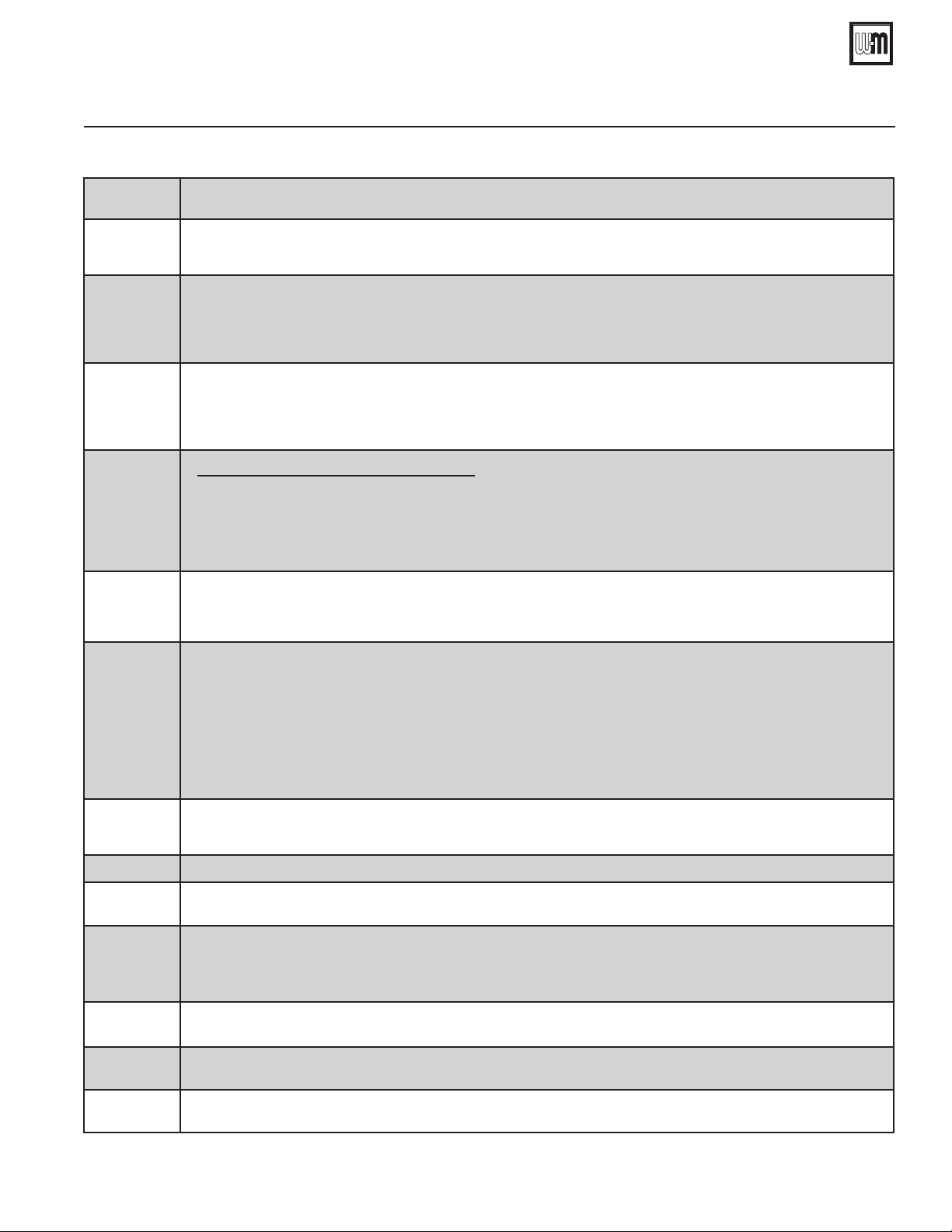
AquaBalance® SERIES 2 WALL MOUNT GAS-FIRED WATER BOILER — Boiler Manual
34 Troubleshooting (continued)
Figure 118 Troubleshooting suggestions — Fault displays and diagnostics (continued)
Display Condition
FAULT 34 =
FAULT 35 =
FAULT 37 =
FAULT 39 =
FAULT 40 =
FAULT 43 =
Low voltage (less than 100VAC) will trigger this error. This is only an indication, the heat request is not switched off.
When voltage brought is back (over 100VAC), error is resolved. (more than 1 pump wired to pump connection point).
The controller measures a voltage supply frequency different from the voltage supply frequency parameter. This is only an indication, the heat request is not switched off. When the controller will measure a voltage supply frequency equal to the Voltage supply frequency parameter, error will be resolved.
(Example 60 Hz).
Low water pressure error can be caused by the low water pressure in the central heating system. This can be
GHWHFWHGLQZD\VYLDORZZDWHUSUHVVXUHVZLWFKDQGYLDZDWHUSUHVVXUHVHQVRUZLWKDFRQ¿UPLQJWLPHRI
seconds). In error mode, the heat demand and the pumps are switched off. See Pressure supervision of the
central heating installation paragraph.
Outside sensor out of normal operating range (short circuit or open circuit). If sensor goes in short circuit and this
condition lasts for more than 10 seconds, error is generated. In case sensor is back to the normal operating range,
error is gone. Normal operating range for the outside sensor is from -22°F till +158°F. With sensor broken in a way
that he makes an open circuit, error will be generated only if a curve is selected: OTC will be disabled but heating
PRGHZLOOEHSRVVLEOH,QFDVHRUPRUHVHQVRUVDUHEURNHQFRQWUROOHUZLOOSLFNXSWKH¿UVWWKDWZDVRXWVLGHWKH
operating range. Resolving error situation can be achieved only if the sensors is within operating range again.
High water pressure error, caused by the water pressure sensor. Water pressure is higher than high level (with
DFRQ¿UPLQJWLPHRIVHFRQGV,QHUURUPRGHWKHKHDWGHPDQGDQGWKHSXPSVDUHVZLWFKHGRII6HH3UHVVXUH
supervision of the central heating installation paragraph.
If the slope temperature felt by the CH supply sensor is greater of Heat exchanger protection parameter, a fault
is generated due to the lack of water of the system. When the temperature felt by the CH supply sensor goes
down under the 113°F, the boiler comes back into the normal operation. Each CH or Installer Test mode demand
WKHIXQFWLRQLVGLVDEOHGIRUWKH¿UVWVHFRQGVVWDUWLQJIURP*DVYDOYHRSHQLQJPRPHQW(DFK'+:GHPDQGWKH
IXQFWLRQLVGLVDEOHGIRUWKH¿UVWVHFRQGVVWDUWLQJIURP*DVYDOYHRSHQLQJPRPHQW([FHSWIRUFRPIRUW0RGH
LI'+:FRQ¿JXUDWLRQSDUDPHWHULVVHWWRLQWKLVFDVHWKHIXQFWLRQLVDFWLYHDVVRRQDVWKH*DVYDOYHRSHQLQJ
PRPHQW,QFDVH'+:FRQ¿JXUDWLRQSDUDPHWHULVVHWWRDQGLQFDVHRI'+:PRGHLVUXQQLQJDQG,QVWDOOHU7HVW
PRGHGHPDQGLVFUHDWHGWKHIXQFWLRQLVGLVDEOHGIRUWKH¿UVWVHFRQGV
FAULT 47 =
FAULT 50 =
FAULT 51 =
FAULT 52 =
FAULT 53 =
FAULT 64 =
FAULT 66 =
Part number 550-100-325/0718
Water pressure sensor not connected. In error mode, the heat demand and the pumps are switched off.
Resolving error situation can be achieved only if the sensor is connected again.
Variable input switch contact opened. See Variable input switch paragraph.
Low water cutoff sensor open. This error can occur only when the Variable input switch functionality parameter is
set to 3. This is only an indication, the heat request is not switched off.
When the system measures a difference between two CH supply water temperature sensors equal or higher than
)ZLWKDFRQ¿UPLQJWLPHRIVHFRQGVHUURULVFUHDWHG7KLVHUURUFRQGLWLRQLVVWRSSLQJWKHERLOHUDQGWR
get to the normal operation again, the temperature between the two CH supply water temperature sensors has to
be lower than 14°F for 10 seconds. When this timer is expired, error will be resolved.
High limit thermostat open. This error can occur only when the Variable input switch functionality parameter is set
to 4. During fault the boiler is forced in stand-by mode. Blue jumper wire missing on Heating Only boiler.
5 MicroCom reset in 15 minutes time frame. This error condition is stopping the boiler and to get to the normal
operation again, it is necessary to take out main power supply.
Software doesn’t match. This error condition is stopping the boiler and to get to the normal operation again, it is
necessary to re-program the device or to replace it.
93
Page 94
AquaBalance® SERIES 2 WALL MOUNT GAS-FIRED WATER BOILER — Boiler Manual
34 Troubleshooting (continued)
Figure 119 Configuration mode — Parameters, Descriptions, Default displays and Notes
Configuration mode
By pressing the DHW- and DHW+ push buttons together for 10 seconds, it is possible to enter into the Configuration mode.
The display starts with showing “b01” blinking. By means of the CH “+” and CH “-” push buttons it is possible to select the
parameters; between “b01” and “b28”. Selecting one of these parameters, by means of the DHW “+” and DHW “-” push buttons
it is possible to adjust his value (not flashing). The value is automatically saved.
Parameter Description Default Note
b01 *DVW\SHVHOHFWLRQ 1DWXUDO*DV /3* 0
'+:FRQ¿JXUDWLRQ
b02
b03 :DWHUSUHVVXUHSURWHFWLRQ 6ZLWFK 6HQVRU 0
b04 Fan absolute DHW maximum speed (Hz)
b05 Fan absolute CH maximum speed (Hz)
b06 Fan absolute minimum speed (Hz)
b07 1RWLPSOHPHQWHG'+:FRQ¿J
6WRUDJHWDQN
,QVWDQWDQHRXVZLWKVHFRQGDU\KHDWH[FKDQJHU
'+:PD[LPXPRXWSXWERRVWOLPLWOHYHO'+:FRQ¿J
2 - Heating Only
3 - Combi
See
Figure 124, page 97.
See
Figure 124, page 97.
See
Figure 124, page 97.
--
100
DHW conf. dependent
Do Not Adjust
b08 1RWLPSOHPHQWHG'+:FRQ¿J
b09 Fan offset low level (Hz) 10 Do Not Adjust
b10 6XPPHU:LQWHUIXQFWLRQ 6XP:LQ DOZD\V:LQ 1 Do Not Adjust
b11 Variable input switch functionality (Number) 4 Do Not Adjust
b12 Variable output relay functionality (Number)
b13 External pcb variable output relay functionality (Number) 7 Do Not Adjust
b14 +RXUVRIQR'+:ÀRZWRVHWWKH(FRQRP\PRGH+RXUV 24 5DQJH KRXUV
b15 )DXOW)IXQFWLRQ GLVDEOH HQDEOH 0 Do Not Adjust
b16 Maximum exhaust gases temperature (°F) 200
b17 0DLQVXSSO\IUHTXHQF\ +] +] 1 Do Not Adjust
b18
b19 '+:WDQNSUHSDUHPRGH1XP'+:FRQ¿J
b20 )DQW\SHVHOHFWLRQ 1RWXVHG (EP 1 Do Not Adjust
b21 Pump protection time (Sec) 5 Do Not Adjust
b22 PVC/CPVC/Polypro/AL29-4C Selection 1 See Options on page 32
b23 PVC maximum temperature (°F) 190 Do Not Adjust
b24 CPVC maximum temperature (°F) 200 Do Not Adjust
b25 Pre-purge time between A01 attempts 0 Do Not Adjust
b26 High altitude & Chimney length selection 0 Do Not Adjust
b27 +\GUDXOLFFRQ¿JXUDWLRQ'+:FRQ¿J
b28 2IIVHWÀDPHFXUUHQWORZOLPLW 20 Do Not Adjust
'+:PD[LPXPRXWSXWERRVWOLPLWWLPH6HF'+:FRQ¿J
Figure 124, page 97
1RWLPSOHPHQWHG'+:FRQ¿J
1RWLPSOHPHQWHG'+:FRQ¿J
'+:ÀRZVHQVRU¿OWHU6HF'+:FRQ¿J
1RWLPSOHPHQWHG'+:FRQ¿J
--
60
See
--
--
0
0
0
--
DHW conf. dependent
Do Not Adjust
Model dependent
200 PVC/ 212 CPVC
sel. dependent
DHW conf. dependent
Not used,
Do Not Adjust
DHW conf. dependent
Do Not Adjust
DHW conf. dependent
Do Not Adjust
By pressing the DHW- and DHW+ push buttons together for 10 seconds, it is possible to leave the Configuration mode.
If no action has been taken, the MMI automatically leaves this mode after 2 minutes.
94
Part number 550-100-325/0718
Page 95
AquaBalance® SERIES 2 WALL MOUNT GAS-FIRED WATER BOILER — Boiler Manual
34 Troubleshooting (continued)
Figure 120 Installer mode
Installer mode
By pressing the “reset” push button for 20 seconds, it is possible to entered the Installer mode. During this time, the OTC mode
must not be entered. The display starts showing: “tS” flashing. By means of the CH+ and CH- push buttons it is possible to select
“tS” or “In” or “Hi” or “rE”. “tS” means “Transparent parameter”; “In” means “Inquiry”; “Hi” means “History”; “rE” means “
tS blinking
Transparent parameter mode See Figure 121 thru 124, pages 95-97.
In blinking
Inquiry mode See Figure 125 & 127, pages 97-98.
Hi blinking
History mode See Figure 127, page 98.
rE blinking
Reset all the History information
reset”.
By means of the “
reset” button (1 activation for 1 second) on “tS” it is possible to enter the “Transparent parameter” mode, on “In”
it is possible to enter the “Inquiry” mode, on “Hi” is possible to enter the “History” mode; by means of the “eco” button (1 activation for 3 seconds) on “rE” is possible to reset all the History information.
By pressing the “
reset” button for 20 seconds, it is possible to leave the Installer mode. If no action has been taken, the control
automatically leaves this mode after 2 minutes.
“tS” as Transparent Parameters mode (TSP)
Selecting “tS” the display starts with showing “P01” blinking. By means of the CH+ and CH- push buttons it is possible to select
the parameters; between “P01” and “P34”. Selecting one of these parameters, by means of the DHW+ and DHW- push buttons is
possible to adjust his value (not flashing). To save, press the DHW- and DHW+ push buttons together.
The default “tS”settings for the boiler have been set by the Manufacturer and there should be no need to change.
Figure 121 “tS” - Transparent Parameter mode
Parameter Description Default Notes
P01
P02
P03
P04
Ignition level (%)
CH slope control (°F/min) 6
Minimum Virtual set point (°F) 95 Do Not Adjust
CH OFF time (Min) 2
60 or 80
or 50
60% - AB-120 / 80% - AB-80
50% - AB-155
P05
P06
P07
P08
P09
P10
P11
P12
P13
Part number 550-100-325/0718
CH pump over-run time (Sec) 15
CH pump selection (0-7) 0 Do Not Adjust
CH modulating pump PWM absolute min (%) 30 Do Not Adjust
CH modulating pump PWM start (%) 75 Do Not Adjust
CH modulating pump PWM absolute max (%) 100 Do Not Adjust
&+VXSSO\IRU&+SXPSRYHUUXQ2)))'+:FRQ¿J
&+VXSSO\IRU&+SXPSRYHUUXQ2)))'+:FRQ¿J
&+VXSSO\IRU&+SXPSRYHUUXQ21)'+:FRQ¿J
&+VXSSO\IRU&+SXPSRYHUUXQ21)'+:FRQ¿J
CH set point limit HIGH (°F) 190
CH maximum output (%) 100 Also in Test Mode
68
91
18
DHW conf. dependent
&RQ¿J+HDWLQJ2QO\
&RQ¿J&RPEL
9
DHW conf. dependent
&RQ¿J+HDWLQJ2QO\
&RQ¿J&RPEL
95
Page 96
AquaBalance® SERIES 2 WALL MOUNT GAS-FIRED WATER BOILER — Boiler Manual
34 Troubleshooting (continued)
Figure 122 “tS” - Transparent Parameter mode (continued)
Parameter Description Default Note
P14
P15
P16
P17
P18
P19
P20
P21
P22
P23
P24
P25
P26
P27
P28
P29
P30
P31
P32
P33
P34
/HJLRQHOODSURWHFWLRQ'+:FRQ¿JZLWKVHQVRU
/HJLRQHOODSURWHFWLRQ'+:FRQ¿JZLWKWKHUPRVWDW
'+:RIIPRGH'+:FRQ¿J
'+:&RPIRUW+\VWHUHVLV)'+:FRQ¿J
'+:&RPIRUWVZLWFKRQSRLQW)'+:FRQ¿J
&+VXSSO\RYHUWHPSBEXUQHU21)'+:FRQ¿J
'+:&RPIRUWWHPSHUDWXUHGLIIHUHQFH)'+:FRQ¿J
'+:GHOWD)'+:FRQ¿J
'+:2))WLPH6HF'+:FRQ¿J
'+:VHWSRLQWOLPLW+,*+)'+:FRQ¿J
'+:VHWSRLQWOLPLW+,*+)'+:FRQ¿J
'+:SXPSRYHUUXQWLPH6HF'+:FRQ¿J
'+:SXPSRYHUUXQWLPH6HF'+:FRQ¿J
DHW maximum output (%) 100
1RWLPSOHPHQWHG'+:FRQ¿J
1RWLPSOHPHQWHG'+:FRQ¿J
'+:FRPIRUWRIIWLPH0LQ'+:FRQ¿J
1RWLPSOHPHQWHG'+:FRQ¿J
1RWLPSOHPHQWHG'+:FRQ¿J
Blower speed in Stand-by mode (Hz) 0
Post-Ventilation time (Sec) 27
'HOWD7)'+:FRQ¿J
'HOWD7)'+:FRQ¿J
'HOWD7)'+:FRQ¿J
'HOWD7)'+:FRQ¿J
Water pressure low limit (psi) 6
Water pressure nominal (psi) 10
1RWLPSOHPHQWHG'+:FRQ¿J
+HDWH[FKDQJHUSURWHFWLRQ)6HF'+:FRQ¿J
CH hysteresis after burner ignition (°F) 18
CH hysteresis after burner ignition timer (Sec) 60
'+:VORSHFRQWURO)PLQ'+:FRQ¿J
1RWLPSOHPHQWHG'+:FRQ¿J
3ULRULW\2YHU5LGH6HWPLQ'+:FRQ¿J
1RWLPSOHPHQWHG'+:FRQ¿J
3ULRULW\2YHU5LGH5HVHWPLQ'+:FRQ¿J
1RWLPSOHPHQWHG'+:FRQ¿J
0
-0
4
104
176
36
18
120
149
131
30
30
--
--
42
--
--
32
32
63
255
--
18
9
--
30
--
15
--
DHW conf. dependent
DHW conf. dependent
DHW conf. dependent
DHW conf. dependent
DHW conf. dependent
DHW conf. dependent
DHW conf. dependent
DHW conf. dependent
DHW conf. dependent
DHW conf. dependent
Fixed if the Water pressure
SURWHFWLRQLVVHW 6ZLWFK
Fixed if the Water pressure
SURWHFWLRQLVVHW 6ZLWFK
DHW conf. dependent
DHW conf. dependent
DHW conf. dependent
DHW conf. dependent
Not Used
Not Used
96
Part number 550-100-325/0718
Page 97
AquaBalance® SERIES 2 WALL MOUNT GAS-FIRED WATER BOILER — Boiler Manual
34 Troubleshooting (continued)
Figure 123 “tS” - Transparent Parameter mode (continued)
By pressing the “reset” push button for 1 second, it is possible to escape from the “Transparent parameter” mode. By pressing the
“reset” push button for 20 seconds, it is possible to leave the Installer mode. If no action has been taken, the MMI automatically
leaves this mode after 15 minutes.
Figure 124 Default Control Board “Transparent Parameters”
Boiler
Model
AB-80-N-C
AB-120-N-C
AB-155-N-C
AB-80-N-H
AB-120-N-H
AB-155-N-H
AB-80-LP-C
AB-120-LP-C
AB-155-LP-C
AB-80-LP-H
AB-120-LP-H
AB-155-LP-H
“b01” “b02” “b04” “b05” “b06” “b10” “b12”
Gas
type
1DWJDV
1DWJDV
1DWJDV
1DWJDV
1DWJDV
1DWJDV
/3*
/3*
/3*
/3*
/3*
/3*
Boiler
type
3 155 155 35 1 0 1 80 6 2
3 200 200 40 1 0 1 60 6 2
3 205 210 39 1 7 1 50 6 2
2 155 155 40 1 0 1 80 6 2
2 200 200 40 1 0 1 60 6 2
2 205 210 39 1 0 1 50 6 2
3 145 145 35 1 0 1 80 6 2
3 185 185 40 1 0 1 60 6 2
3 210 220 40 1 7 1 50 6 2
2 145 145 35 1 0 1 80 6 2
2 185 185 40 1 0 1 60 6 2
2 210 220 40 1 0 1 50 6 2
Fan
Max. Freq.
in DHW
Fan
Max. Freq.
in CH
Fan
Min. Freq.
in CH
S/W mode
selection
button
Var. Out
Relay
“b22”
Vent
material
“P01” “P02” “P04”
Ignition
level
CH Slope
(F/min)
CH
Off Time
Figure 125 “In” - Inquiry mode
t01 blinking
CH Supply sensor1 Temperature (°F) between 32 and 257
t02 blinking
CH Supply sensor2 Temperature (°F) between 32 and 257
t03 blinking
CH Return sensor Temperature (°F) between 32 and 257
t04 blinking
DHW sensor Temperature (°F) between 32 and 257
t05 blinking
Outdoor sensor Temperature (°F) between -22 and 158, blinking if it is negative
t06 blinking
Exhaust sensor Temperature (°F) between 32 and 257
F07 blinking
Actual Blower Speed (Hz) 0LQ 0D[ SDUDPHWHUGHSHQGLQJ
L08 blinking
Actual burner load (%) 0LQ 0D['+:ERRVWRXWSXW
F09 blinking
$FWXDOZDWHUÀRZUDWH OPLQ between 00 and 255
“In” as Inquiry mode
Selecting “In” the display starts with showing “t01” blinking. By means of the CH+ and CH- push buttons it is possible to select the
parameters; between “t01” and “F13”. Selecting one of these parameters, by means of the DHW+ and DHW- push buttons is pos-
sible to see his value (not flashing; only in case of negative outdoor temperature the value is flashing).
Part number 550-100-325/0718
97
Page 98
AquaBalance® SERIES 2 WALL MOUNT GAS-FIRED WATER BOILER — Boiler Manual
34 Troubleshooting (continued)
Figure 126 “In” - Inquiry mode (continued)
P10 blinking
Boiler water pressure switch status 2SHQ &ORVHG
P11 blinking
Actual PWM modulating Pump (%) 0LQ 0D[
P12 blinking
Actual Step of Triac mod. mode (Num) 0LQ 0D[
F13 blinking
$FWXDO)ODPH&XUUHQW X$ between 00 and 255
• If a temperature sensor is in an open circuit or short circuit condition, the display shows “--”.
• Actual blower speed is shown always in terms of Hz.
• Actual water flow rate is shown in terms of real l/min *10 and it has to be visualized also with the input switch
contact open. Example: real 1.5 l/min has to be visualized as 15.
• Actual Flame Current is shown in terms of real uA*10. Example: real 0.3 uA*10 is shown as 3.
• In case of DHW thermostat, t04: “On” means closed, “OFF” means open.
By pressing the “
reset” push button for 1 second, it is possible to escape from the “Inquiry” mode. By pressing the “reset” push
button for 20 seconds, it is possible to leave the Installer mode. If no action has been taken, the MMI automatically leaves this
mode after 15 minutes.
“Hi” as History mode
Selecting “Hi” the display starts with showing “H01” blinking. By means of the CH+ and CH- push buttons it is possible to select
the parameters; between “H01” and “H08”. Selecting one of these parameters, by means of the DHW+ and DHW- push buttons, it
is possible to see the past error codes (not flashing).
Figure 127 “Hi” - History mode
H01 blinking
History buffer 1 (the latest)
H02 blinking
History buffer 2
H03 blinking
History buffer 3
-------- --------
H08 blinking
History buffer 08
By pressing the “
reset” push button for 1 second, it is possible to escape from the “History” mode. By pressing the “reset” push
button for 20 seconds, it is possible to leave the Installer mode. If no action has been taken, the MMI automatically leaves this
mode after 15 minutes.
98
Part number 550-100-325/0718
Page 99
AquaBalance® SERIES 2 WALL MOUNT GAS-FIRED WATER BOILER — Boiler Manual
34 Troubleshooting (continued)
Figure 128 Troubleshooting suggestions for AquaBalance
®
boilers — Fault displays and diagnostics (continued)
System Parameters list (default settings)
There are 4 basic configurations within the DHW mode, selected by parameter DHW configuration (see Parameters list, Num.
1). Default value is model dependent. (2 for Heating Only models, 3 for Combi models). By changing the DHW configuration
number (See Parameter “b01”, Figure 118, page 94), all the data will be automatically set at default condition. Parameters that will
be changed according to the DHW mode are numbered from 9 to 46 (see Parameters list). All the parameters can be accessed with
a communication package running on the PC. Some parameters are available by the installer in the “ts”, Transparent Parameter
mode through the control interface.
Table 5 AquaBalance® list of System parameters (default settings)
Category E2 prom parameters Unit Range Def
Description
DHW boiler type 1 CL5 – 05C8 '+:FRQ¿JXUDWLRQ Num 1 4 3
System 2 ML – 80D0 )LUVWVWDUWXSÀDJ Num 0 1 0
End user setting 3 ML – 80E2 Summer / Winter selection Num 0 1 1
End user setting 4 ML – 80E3 Economy / Comfort selection Num 0 1 0
End user setting 5 CL5 – 0A9D CH set point limit - HIGH °F 68 194 190
Num. Address Description Low High Value
End user setting 6 CL5 – 056D CH user set point °F 68 194 158
Exhaust protection 7 CL5 – 050B Maximum exhaust gases temperature °F 32 255 185
Firmware version 8 ML – 80E8 Firmware version Num 0 99 04
Part number 550-100-325/0718
99
Page 100
AquaBalance® SERIES 2 WALL MOUNT GAS-FIRED WATER BOILER — Boiler Manual
34 Troubleshooting (continued)
Figure 129 Troubleshooting suggestions for AquaBalance
®
boilers — Fault displays and diagnostics (continued)
Category E2 prom parameters Unit Range Def
Description
'+:FRQ¿J 9,2 CL5 – 066E DHW P factor Num 0 255 5
'+:FRQ¿J 10,2 CL5 – 0691 DHW I factor Num 0 255 240
'+:FRQ¿J 11,2 ML – 80EB DHW FF factor Num 0 255 0
'+:FRQ¿J 12,2 ML – 80EC Fan absolute DHW maximum speed Hz 0 220 200
'+:FRQ¿J 13,2 ML – 80ED Fan absolute CH maximum speed Hz 0 220 200
'+:FRQ¿J 14,2 ML – 80EE Fan absolute minimum speed Hz 0 165 40
'+:FRQ¿J 15,2 CL5 – 2D89 Fan offset low level Hz 0 220 10
'+:FRQ¿J 16,2 ML – 80F0 Ignition level % 0 100 60
'+:FRQ¿J 17,2 Free - TBD
'+:FRQ¿J 18,2 Free - TBD
'+:FRQ¿J 19,2 Free - TBD
'+:FRQ¿J 20,2 Free - TBD
'+:FRQ¿J 21,2 Free - TBD
'+:FRQ¿J 22,2 Free - TBD
'+:FRQ¿J 23,2 Free - TBD
'+:FRQ¿J 24,2 Free - TBD
'+:FRQ¿J 25,2 Free - TBD
'+:FRQ¿J 26,2 ML – 80FA DHW pre-pump time Sec 0 30 30
'+:FRQ¿J 27,2 ML – 80FB Legionella protection Num 0 7 0
'+:FRQ¿J 28,2 CL5 – 0A5E DHW comfort hysteresis °F 0 176 4
'+:FRQ¿J 29,2 CL5 – 0A62 DHW comfort temp difference °F 0 104 0
'+:FRQ¿J 30,2 ML – 80FE DHW pump start temperature °F 0 255 32
'+:FRQ¿J 31,2 ML – 80FF DHW pump start waiting time Sec 0 255 0
'+:FRQ¿J 32,2 CL5 – 05A1 DHW OFF time Sec 30 255 120
'+:FRQ¿J 33,2 CL5 – 0A04 DHW pump over-run time Sec 0 255 30
'+:FRQ¿J 34,2 CL5 – 0A6D Delta T1 °F 0 108 32
'+:FRQ¿J 35,2 CL5 – 0A92 Delta T2 °F 0 255 63
'+:FRQ¿J 36,2 ML – 8104 CH supply for CH pump over-run OFF °F 32 212 68
'+:FRQ¿J 37,2 CL5 – 0C94 CH supply for CH pump over-run ON °F 0 200 9
'+:FRQ¿J 38,2 ML – 8106 CH supply over-temp_burnerOFF °F 0 212 9
'+:FRQ¿J 39,2 ML – 8107 CH supply over-temp_burnerON °F 32 212 176
'+:FRQ¿J 40,2 ML – 8108 CH return over-temp_burnerOFF °F 32 212 203
'+:FRQ¿J 41,2 ML – 8109 CH return over-temp_burnerON °F 32 212 194
'+:FRQ¿J 42,2 ML – 810A DHW set point limit – LOW °F 50 104 50
'+:FRQ¿J 43,2 CL5 – 1E76 DHW set point limit – HIGH °F 104 158 149
'+:FRQ¿J 44,2 CL5 – 05F4 DHW user set point – Default value °F 50 158 149
'+:FRQ¿J 45,2 ML – 810D CH pre-pump time Sec 0 60 30
'+:FRQ¿J 46,2 ML – 810E Minimum virtual set point °F 68 176 95
Num. Address Description Low High Value
100
Part number 550-100-325/0718
 Loading...