

Page 1
®
®
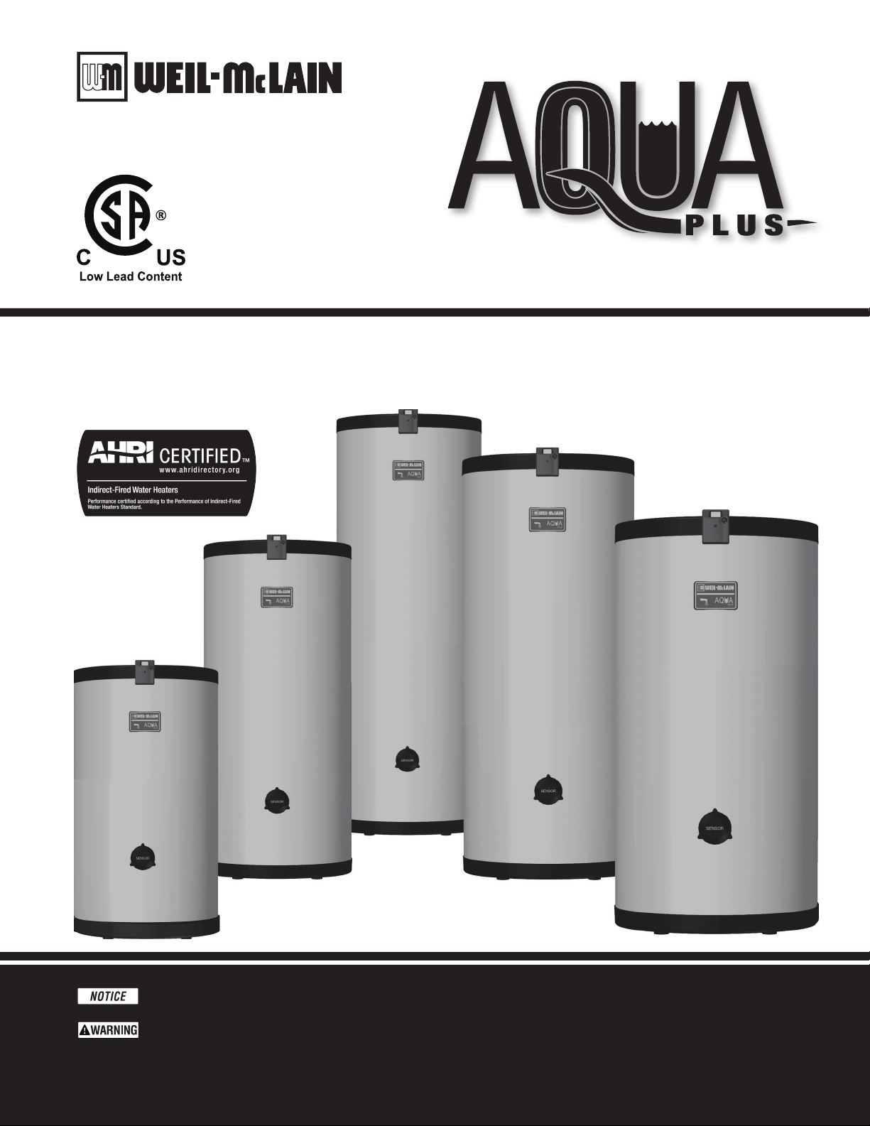
Series 2
Indirect-Fired Water Heaters
Product Manual
®
• Installation
• Startup
• Maintenance
• Parts
User — Read important user safety information found on page 3, page 27 and page 28. Installation and service should only be
performed by a qualified service technician. Retain this manual for future reference.
This manual must only be used by a qualified heating installer/service technician. BEFORE installing, read all instructions
in this manual and all other information shipped with the water heater. Perform steps in the order given. Failure to comply
could result in severe personal injury, death or substantial property damage.
Part number 633-600-020/0118
Page 2

AQUA PLUS® Series 2 indirect-fired water heaters — Product Manual
Contents
Please read before proceeding 3
When servicing water heater . . . . . . . . . . . . . . . . . . . . 3
Operating restrictions . . . . . . . . . . . . . . . . . . . . . . . .3
Boiler water restrictions . . . . . . . . . . . . . . . . . . . . . . . 3
Location . . . . . . . . . . . . . . . . . . . . . . . . . . . . . . . 3
Pre-installation 4
Codes . . . . . . . . . . . . . . . . . . . . . . . . . . . . . . . . .4
Code restrictions . . . . . . . . . . . . . . . . . . . . . . . . . . . 4
Water heater placement . . . . . . . . . . . . . . . . . . . . . . .4
Install levelling legs . . . . . . . . . . . . . . . . . . . . . . . . . 4
Domestic water piping requirements. . . . . . . . . . . . . . . . 5
Water heater operating restrictions. . . . . . . . . . . . . . . . . 5
Boiler water restrictions . . . . . . . . . . . . . . . . . . . . . . . 5
Hot Water Can Scald! . . . . . . . . . . . . . . . . . . . . . . . . 5
Domestic water piping 6
Piping overview . . . . . . . . . . . . . . . . . . . . . . . . . . . 6
Recirculation 8
Maintaining domestic water temperature in the supply piping . 8
Time delay at fixtures . . . . . . . . . . . . . . . . . . . . . . . . 8
Balancing . . . . . . . . . . . . . . . . . . . . . . . . . . . . . . .8
Components required . . . . . . . . . . . . . . . . . . . . . . . .8
Connecting to the water heater . . . . . . . . . . . . . . . . . . .8
Components . . . . . . . . . . . . . . . . . . . . . . . . . . . . 10
Operation. . . . . . . . . . . . . . . . . . . . . . . . . . . . . . 10
Potential problems . . . . . . . . . . . . . . . . . . . . . . . . . 10
Wiring — zoning with circulators 23
Wiring — zoning with zone valves 23
Mounting and wiring the Control - New Installations 24
Setting the Thermostat Control 25
Water heater filling and start-up 26
Boiler water restrictions . . . . . . . . . . . . . . . . . . . . . . 26
Maximum boiler-side flow rate . . . . . . . . . . . . . . . . . . 26
Filling the domestic water tank . . . . . . . . . . . . . . . . . . 26
Start-up and operation . . . . . . . . . . . . . . . . . . . . . . 26
Start-up checklist . . . . . . . . . . . . . . . . . . . . . . . . . 26
Water heater temperature adjustment 27
Setting the thermostat . . . . . . . . . . . . . . . . . . . . . . . 27
Hot Water Can Scald! . . . . . . . . . . . . . . . . . . . . . . . 27
Water heater maintenance 28
ANNUAL start-up by qualified service technician . . . . . . . 28
Drain the water heater if necessary during shutdown periods . 28
Troubleshooting 29
Troubleshooting procedures 29
Preparation for troubleshooting . . . . . . . . . . . . . . . . . 29
Boiler-side piping 11
Connecting to a low-pressure steam boiler 18
Filling the piping. . . . . . . . . . . . . . . . . . . . . . . . . . 19
Boiler-side wiring and controls 20
Wiring requirements. . . . . . . . . . . . . . . . . . . . . . . . 20
Circulators . . . . . . . . . . . . . . . . . . . . . . . . . . . . . 20
Zone Valves. . . . . . . . . . . . . . . . . . . . . . . . . . . . . 20
Wiring to the water heater. . . . . . . . . . . . . . . . . . . . . 20
Wiring options . . . . . . . . . . . . . . . . . . . . . . . . . . . 20
Use domestic priority . . . . . . . . . . . . . . . . . . . . . . . 20
2
Replacement parts 38
Rating - AQUA PLUS® Series 2 39
Ratings with 200°F boiler supply water 40
Ratings with 190°F boiler supply water 41
Ratings with 180°F boiler supply water 42
Dimensions 43
Part number 633-600-020/0118
Page 3
AQUA PLUS® Series 2 indirect-fired water heaters — Product Manual
Please read before proceeding
Hazard definitions
The following defined terms are used throughout this
manual to bring attention to the presence of hazards
of various risk levels or to important information
concerning the life of the product.
Indicates presence of hazards that will
cause severe personal injury, death or
substantial property damage.
Indicates presence of hazards that can
cause severe personal injury, death or
substantial property damage.
Indicates presence of hazards that will
or can cause minor personal injury or
property damage.
Indicates special instructions on installa-
tion, operation or maintenance that are
important but not related to personal
injury or property damage.
This manual provides installation and
operation guidelines for Weil-McLain
AQUA PLUS® indirect water heaters.
The installer is responsible for ensuring
that the installation complies with this
manual, the boiler manual and all applicable codes.
Massachusetts installations — The
water heater must be installed by a licensed plumber. The installation must
follow all Massachusetts code requirements. The domestic water piping must
comply with the piping shown in this
manual. See “Domestic water piping,”
page 6, for details and code requirements.
Failure to adhere to the guidelines on this page can
result in severe personal injury, death or substantial
property damage.
Read all instructions before installing. Failure to follow all instructions in proper order can cause severe personal injury, death or
substantial property damage.
When servicing water heater
• To avoid electric shock, disconnect electrical supply before
performing maintenance.
• To avoid severe burns, allow water heater to cool before performing maintenance.
Operating restrictions
• Maximum domestic hot water temperature: residential sizes
— 160°F, commercial sizes — 180°F. Pay attention to the
water temperature warnings throughout this manual.
• Maximum boiler water temperature — 200°F.
• Maximum working pressure for tank — 150 PSIG.
• Water chemistry limits:
• hardness — less than 6 grains/gal.
• pH — above 6 and less than 8.
• chlorides — less than 200 ppm.
Boiler water restrictions
• Thoroughly flush the boiler system (without water heater
connected) to remove sediment.
• The water heater heat exchanger can be damaged by build-up
or corrosion due to sediment.
• Boiler water (including additives) must be practically nontoxic, having toxicity rating or class of 1, as listed in Clinical
Toxicology of Commercial Products.
• If antifreeze is used in boiler system:
• Local codes may require a backflow preventer on cold
water supply line.
• Use antifreeze specifically intended for hydronic heating
systems. Inhibited propylene glycol is recommended.
• Follow boiler manual instructions for antifreeze usage.
• Do not use automotive, ethylene glycol or petroleum-
based antifreeze. Do not use any undiluted antifreeze.
When calling or writing about the water
heater — Please have the water heater serial number from the serial number label,
located on the back side of the water
heater, adjacent to the rating plate.
Any claims for damage or shortage in
shipment must be filed immediately
against the transportation company by
the consignee.
Part number 633-600-020/0118
Location
• This water heater is not intended for outdoor installation.
• Install the water heater so if the tank or any connections
should leak, the water flow will not cause damage to area
near water heater, or to lower floors of structure. When such
locations cannot be avoided, install a suitable drain pan under
water heater. Drain pans are available at your local plumbing
supply store.
• This product is designed for vertical installation only.
3
Page 4
AQUA PLUS® Series 2 indirect-fired water heaters — Product Manual
Pre-installation
Codes
1. Installation must conform with instructions in this
manual and, where applicable:
• local, state, provincial, and national codes, laws,
regulations and ordinances.
• in Canada — B149.1 or B149.2 Installation
Code - latest edition.
2. AQUA PLUS® water heaters are exempt from
ASME Section VIII, Division 1 Code construction
per Interpretation VIII-1-86-136. Check with local
codes for applicability.
3. Where recommendations in this manual differ from
local or national codes, local or national codes take
precedence.
Code restrictions
National Standard Plumbing Code
1. Single-wall heat exchanger in water heater complies
with National Standard Plumbing Code, provided
that:
a. boiler water (including additives) is practically
non-toxic, having toxicity rating or class of 1,
as listed in Clinical Toxicology of Commercial
Products, and
b. boiler water pressure is limited to maximum 30
PSIG by approved relief valve.
Figure 1 Clearance recommendations
Recommended clearances
Installation location must provide adequate clearances for servicing and
proper operation of the water heater. See Figure 1.
• 1” clearance is permissible to either side of water heater, but the Instruction label or other labels may be hidden.
• Top (vertical) clearance is 12” minimum.
• Refer to boiler manual for boiler clearances.
Uniform Plumbing Code
1. Single-wall heat exchangers are permitted if they
satisfy all of the following requirements —
a. The heat transfer medium is potable water or
contains only substances which are recognized
as safe by the U. S. Food and Drug Administration.
b. The pressure of the heat transfer medium is
maintained less than the normal minimum op-
erating pressure of the potable water system.
c. Exception: Steam complying with #a, above.
d. The equipment is permanently labeled to
indicate that only additives recognized as safe
by the FDA shall be used in the heat transfer
medium.
2. Other heat exchanger designs may be permitted
where approved by the Administrative Authority.
Clearance to combustible materials
1. Provide at least ½” clearance between all hot water pipes and combustible materials.
Water heater placement
1. Read and comply with “Location,” page 3 of this manual.
2. Select a convenient location for the water heater, based on domestic
and boiler piping hook-ups.
3. Keeping the distance between boiler and water heater short will:
• reduce piping heat loss.
• provide minimum friction loss.
Install levelling legs
1. Carefully tip the water heater onto its side.
2. Screw the four levelling legs into the base.
3. Return the water heater to the upright position and set in place.
4. Adjust the legs as necessary to level the water heater.
4
Part number 633-600-020/0118
Page 5
AQUA PLUS® Series 2 indirect-fired water heaters — Product Manual
Pre-installation
(continued)
Domestic water piping requirements
1. Install unions on all piping for easy removal of water heater.
2. Use dielectric unions or couplings to protect hot and cold water
fittings from corrosion when connecting dissimilar materials such
as copper and galvanized iron pipe.
3. When the supply pressure is higher than 70 PSIG, install a
pressure reducing valve on cold water supply line to prevent water
loss through T&P relief valve. A thermal expansion tank is also
required.
4. If the water heater will replace a tankless coil in the boiler, disconnect piping to coil or remove coil from boiler and replace with
a cover plate. Allow water to drain from coil.
tankless coil.
Plugging tankless coil inlet and outlet will result in severe
personal injury, death or substantial property damage.
Studies have indicated that dangerous bacteria,
including
the potable water distribution system if certain
minimum water temperatures are not maintained.
Contact your local health department for more
information.
legionella pneumophila, can form in
Do not plug the
Hot Water Can Scald!
• Water heated to temperature for clothes washing,
dish washing and other sanitizing needs can scald
and cause permanent injury.
Boiler water restrictions
1. Read the WARNINGS under “Boiler water restrictions,” page 3.
• Children, elderly, and infirm or physically handicapped persons are more likely to be permanently
injured by hot water. Never leave them unattended
in bathtub or shower. Never allow small children to
use a hot water tap or draw their own bath.
• If anyone using hot water in the building fits
the above description, or if state laws or local
codes require certain water temperatures at
hot water taps, you must take special precautions:
• Use lowest possible temperature setting.
• Install some type of tempering device,
such as an automatic mixing valve, at
hot water tap or water heater. Automatic
mixing valve must be selected and installed
according to valve manufacturer’s recommendations and instructions.
• Water passing out of drain valves may be extremely
hot. To avoid injury:
• Make sure all connections are tight.
• Direct water flow away from any person.
Protection must be taken against excessive temperature and pressure! — Installation of a temperature & pressure (T&P) relief valve (provided
with water heater) and a thermostatic mixing valve
(provided by installer) is required.
Part number 633-600-020/0118
5
Page 6
AQUA PLUS® Series 2 indirect-fired water heaters — Product Manual
Domestic water piping
Piping overview
THERMAL EXPANSION TANK — If a
backflow preventer, check valve, or pressure reducing valve is piped on cold water
inlet of water heater, you must install an
expansion tank on cold water supply line
to prevent normal thermal expansion
from repeatedly forcing open T&P relief
valve.
The T&P relief valve is not intended for
constant duty, such as relief of pressure
due to repeated normal system expansion. Refer to expansion tank manufacturer’s instructions for proper sizing.
Failure to comply could result in severe
personal injury, death or substantial
property damage.
General applications
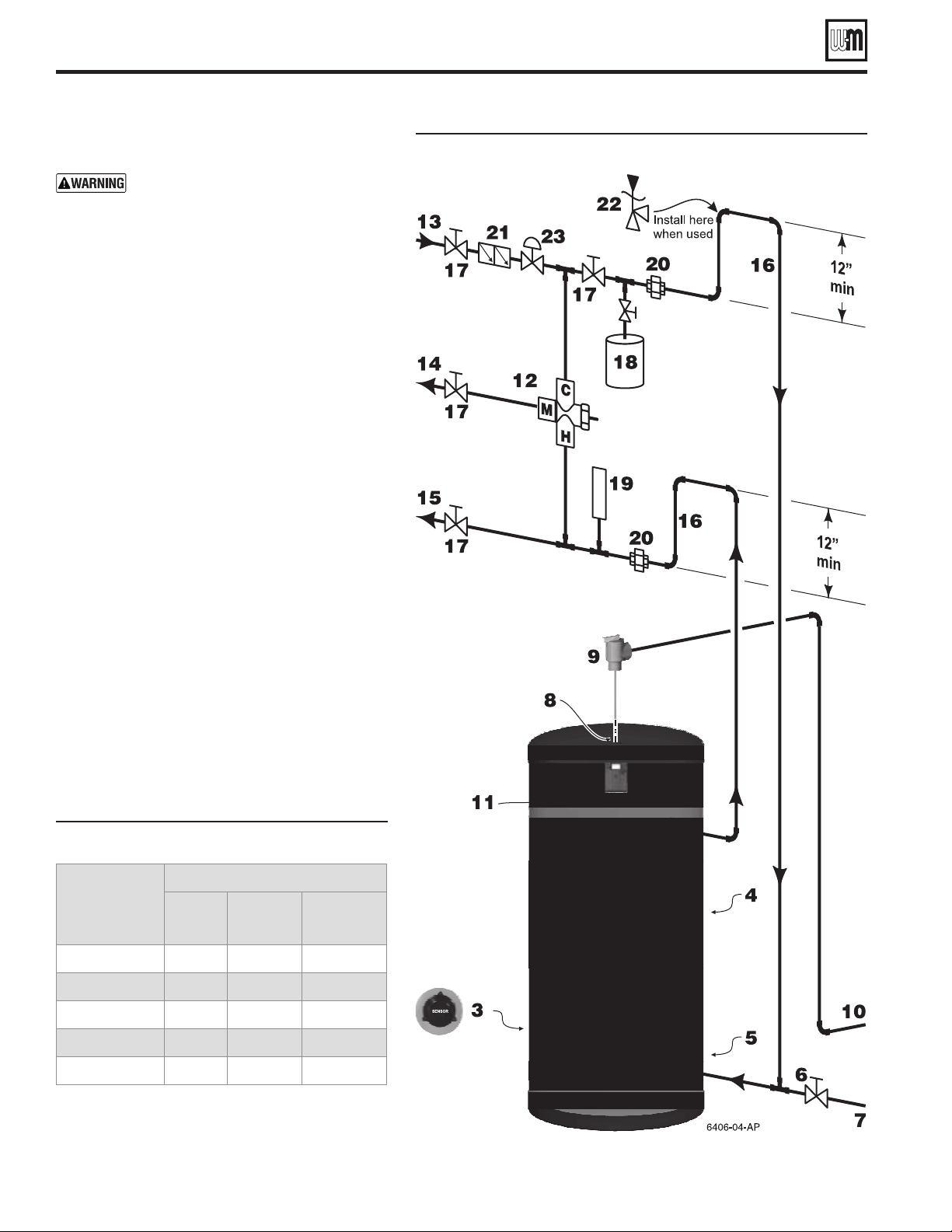
1. Figure 2 — This piping configuration can be used in
most cases, except where local codes require special
components or piping not illustrated.
2. Some codes may require the items listed as optional,
such as a vacuum breaker on the inlet line, or recirculation piping.
Figure 2 DHW piping
Massachusetts applications
1. For Massachusetts code applications, or as
required elsewhere by local codes, install the following options.
a. Thermal siphon on DHW inlet and outlet.
b. Vacuum breaker on domestic water inlet line.
c. Recirculation — Massachusetts code applica-
tions require recirculation piping or heat-traced
piping if the distance from the water heater to
the furthest fixture exceeds 100 feet. See page 8
for details.
Figure 3
Piping connection sizes
Connections (inches NPT)
Model
AQUA PLUS
35
45
55
85
®
DHW
in/out
¾ 1 ¾
¾ 1 ¾
¾ 1 ¾
1 1 ¾
Boiler
water
in/out
Recirculation
tapping
105
6
1 1 ¾
Part number 633-600-020/0118
Page 7

AQUA PLUS® Series 2 indirect-fired water heaters — Product Manual
Domestic water piping
(continued)
LEGEND for Figure 2, page 6
Domestic water supplied to fixtures that could pose
an injury hazard due to high temperature, such as
showers and faucets, should be equipped with a
temperature regulating device, such as an anti-scald
mixing valve
.
When the supply pressure is higher than 70 PSIG,
install a
pressure reducing valve on cold water
supply line to prevent water loss through T&P relief
valve. A thermal expansion tank is also required.
This symbol, where used in this manual, indicates the
item is required by Massachusetts code.
This symbol indicates the item is optional, unless
required by applicable codes.
Domestic cold water inlet connection — see Fig-
1
ure3,page6 for size
2 Domestic hot water outlet connection — see Fig-
ure3,page6 for size
3 Sensor cover — temperature sensor behind cover.
4 Boiler water inlet to coil — see Figure3,page6 for size
5 Boiler water outlet from coil — see Figure3,page6 for
size
Do not install any valve between T&P relief valve and
tank connection, or on T&P relief valve discharge
piping. Do not plug T&P relief valve or its discharge
piping. Improper placement and piping of T&P relief valve can cause severe personal injury, death or
substantial property damage.
Temperature - Electronic Thermostat
11
12 Mixing valve — — RECOMMENDED
• See Replacement parts for thermostatic mixing valves
available from Weil-McLain.
Domestic cold water supply
13
When the water supply pressure is higher than
70 PSIG, install a pressure-reducing valve on the
cold water supply line to prevent leakage from the
T & P relief valve. A thermal expansion tank is also
required.
Domestic mixed-temperature water supply to
14
system
(when used — requires mixing valve)
15 Domestic high-temperature hot water supply to
system
16 Heat trap loops (12” minimum) —
6 Drain valve — provided by installer
• Install a drain valve on the DHW inlet to the water heater
as shown.
Piping from drain valve
7
• Pipe from drain to floor drain, if available.
T&P valve connection
8
9 T&P relief valve — supplied with water heater
• Use only the T&P valve supplied with the water heater.
See Replacement parts for part number.
• Install the T&P relief valve in the top center tapping, as
shown.
T&P relief valve discharge piping —
10
• must be made of material serviceable for temperatures
of 250°F or greater.
• must be directed so that hot water flows away from all
persons.
• must be directed to a suitable place for disposal.
• must be installed so as to allow complete draining of the
T&P relief valve and discharge line.
• must NOT be excessively long — using more than 2 elbows or 15 feet of piping can reduce discharge capacity.
• must NOT be directly connected to a drain — terminate
discharge piping within 6” from floor — refer to local
codes.
• must NOT be plugged, reduced or restricted.
• must NOT be subjected to freezing.
17 Isolation valves
18 Thermal expansion tank —
• REQUIRED if cold water line is equipped with a backflow
preventer or pressure reducing valve — see EXPANSION
T ANK WARNING
Shock arrester —
19
on page 6.
Dishwashers, clothes washers, and fast-closing positive
shutoff valves incorporated in the system all contribute to creating water shock. Install a water hammer
arrester to prevent damage to pipes and appliances.
See control manufacturer’s instructions for application and installation.
Unions
20
• Use dielectric unions or couplings to protect hot and cold
water fittings from corrosion when connecting dissimilar
materials such as copper and galvanized iron pipe.
Backflow preventer — — — (required
21
for Commonwealth of Massachusetts)
22 Vacuum breaker —
23 Pressure reducing valve —
• REQUIRED when the supply pressure is higher than
70 PSIG — A thermal expansion tank is also required.
Part number 633-600-020/0118
7
Page 8

AQUA PLUS® Series 2 indirect-fired water heaters — Product Manual
Recirculation
Massachusetts code applications require recircu-
lation piping or heat-traced piping if the distance
from the water heater to the furthest fixture exceeds
100 feet.
Maintaining domestic water
temperature in the supply piping
1. Recirculation is used to reduce wait time for water use, to
minimize hot water and energy waste caused during the
waiting period, and to prevent degradation of the system
supply water temperature. ASPE recommends recirculation
when the distance from the water heater to the furthest fixture exceeds 100 feet or the time lag for hot water to reach a
fixture(s) exceeds 30 seconds.
2. Consult local codes and American Society of Plumbing
Engineers (ASPE) Domestic Water Heating Design Manual,
1998, for further information.
Time delay at fixtures
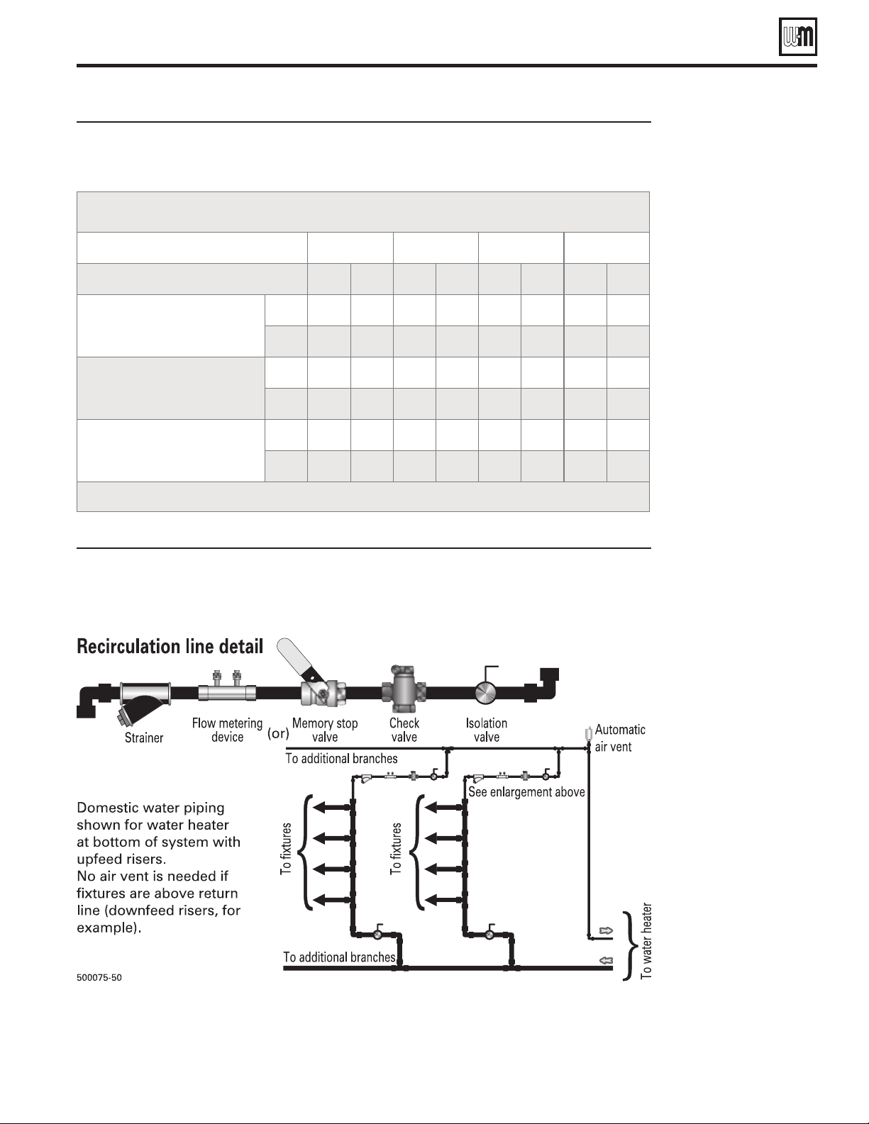
1. Figure 5, page 9 is from the ASPE Domestic Water Heating
Design Manual, 1998. It shows the time required for usable
hot water to arrive at a fixture based on the fixture flow rate
(available from industry and manufacturer’s data) and the
length and diameter of the dead-end branch pipe supplying
the fixture.
2. These branches must be balanced to prevent pipe erosion
and unacceptable time delays at some fixtures.
3. Balancing options include circuit setters, memory stop valves
or factory preset devices (with flow metering provision in
the piping).
Components required
1. For residential applications, consult circulator manufacturer’s
data for circulator selection and additional components
required.
2. On most commercial systems, install the devices shown in
Figure 4, page 9, and any other devices or piping methods
required by local codes.
a. The check valves are required to prevent fixtures from
taking hot water through the return lines.
b. Shutoff valves are needed to allow cleaning and replacing
balancing devices.
c. Include strainers to remove sediment which could
damage the circulator and / or affect the flow balancing
devices.
3. Size the circulator and piping based on the temperature drop
allowed between the water available at the water heater and
the water delivered at the fixture.
2. The time lag should generally not exceed 30 seconds.
3. For residential and office applications, the owner may prefer
a limit of 10 seconds.
4. You can use Figure 5 as a guide to determining the location
of circulation return lines relative to fixtures.
Balancing
1. When multiple branches are connected to the supply piping, each branch must be connected to the recirculation
system.
a. At each of these connections to the return piping, install
shutoff valves, a flow metering device, check valve and a
strainer as shown in Figure 4, page 9.
b. Check local codes for specific installation require-
ments.
a. The return piping will almost always be smaller than the
supply piping, but should never be smaller than ½” to
prevent problems with the circulator.
4. Make provision for removal of air in all return lines. Where
the returns cannot be vented by topmost fixtures in the
system, install automatic air venting at the top of the return
piping.
Connecting to the water heater
1. Install the domestic water components as shown in Figure 2, page 6.
2. See Figure 6, page 10 for the piping required to the water
heater.
— Continued on page 10 —
8
Part number 633-600-020/0118
Page 9
AQUA PLUS® Series 2 indirect-fired water heaters — Product Manual
Recirculation
Figure 5 Time lag to obtain hot water at fixture for branch lengths of 10 and 25 feet (ASPE
Domestic Water Heating Design Manual)
(continued)
Time in seconds required to get hot water at fixture (from ASPE)
Fixture flow rate (GPM) - 0.5 1.5 2.5 4.0
Piping length (feet) - 10 25 10 25 10 25 10 25
Copper pipe ½” 25 63 8 21 5 13 3 8
¾” 48 119 16 40 10 24 6 15
Steel pipe ½” 63 157 21 52 13 31 8 20
¾” 91 228 30 76 18 46 11 28
CPVC pipe ½” 64 159 21 53 13 62 8 20
¾” 95 238 32 79 19 48 12 30
NOTE: Select branch size and length for less than 31 seconds delay.
Figure 4 Recirculation components
Part number 633-600-020/0118
9
Page 10
AQUA PLUS® Series 2 indirect-fired water heaters — Product Manual
Recirculation
(continued)
Components
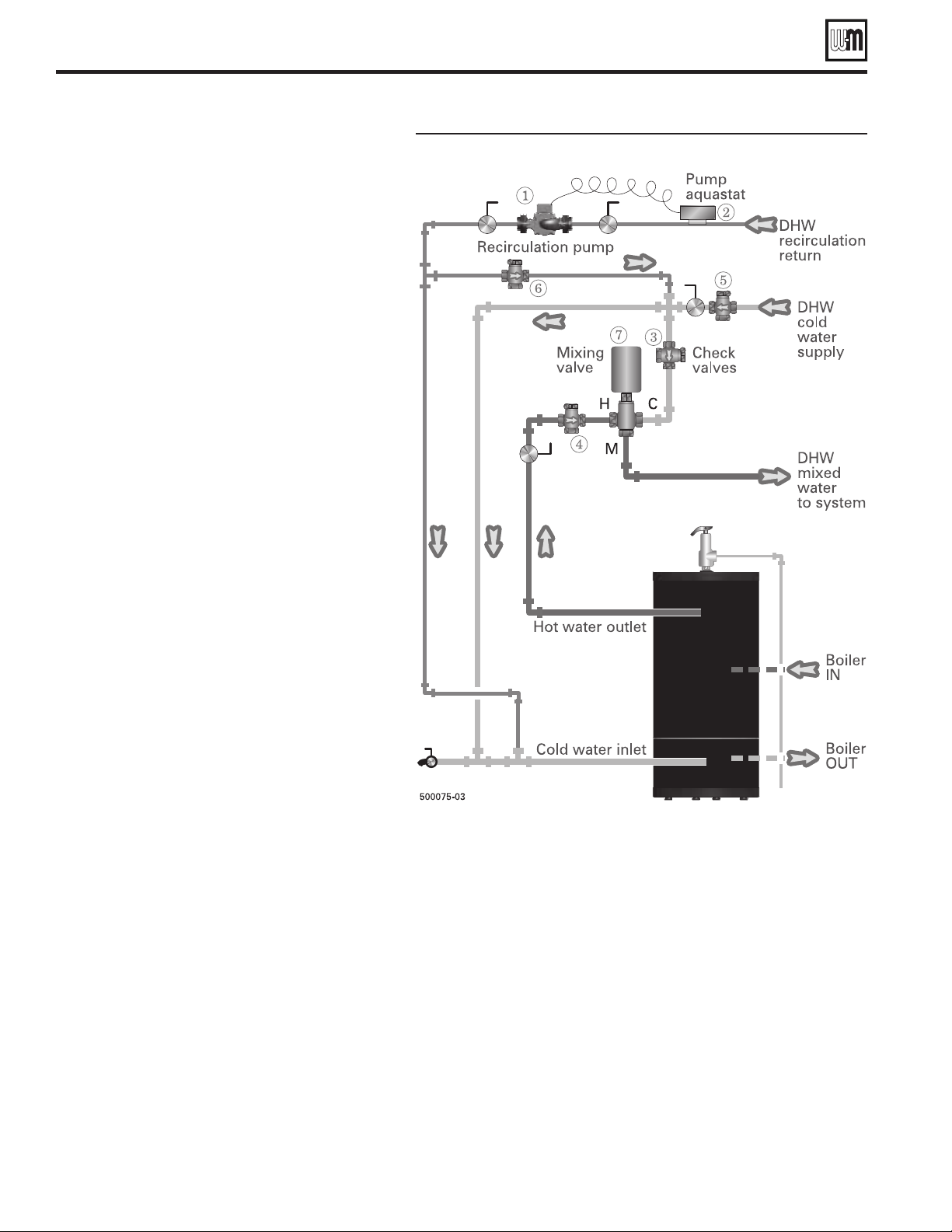
Circulator (Figure 6, item 1)
1. Little flow is required to maintain a temperature
in the piping.
2. Size of circulator depends on minimum flow requirements of the tempering valve.
3. Minimum flow rates of the tempering valve must
be maintained.
Aquastat (Figure 6, item 2)
1. Used to control the on-off position of the circulator. Aquastat is set 5° to 10° lower than mixed water
outlet of the mixing valve (#7).
2. The circulator cannot run continuously as bypass
through the mixing valve will eventually allow the
temperature on the piping to climb to the water
heater temperature during draw periods.
Figure 6 Recirculation piping
Check valves (Figure 6, items 3–6)
1. Assure the flow of water in one direction.
2. Each check valve functions as follows:
a. #3 and #4 prevent bypass in the event of pres-
sure drop.
b. #5 prevents thermal siphoning of hot water to
the cold water supply.
c. #6 prevents flow of cold water to the tempered
water supply. A draw of tempered water will not
result in flow of cold water into the return loop.
Operation
1. During period of normal use (fixtures on) — Circulator is off. There is no flow through #6, there is flow
through #5 equal to the flow at the fixtures, there is
flow through #3 and/or #4 equal to flow at fixture.
2. When all fixtures are off — Circulator is off. There is
no flow through #3, #4, #5 or #6. Water temperature
in piping is cooling.
3. When temperature at aquastat #2 falls 10° below
temperature to be maintained — Circulator is on.
There is flow through #6 equal to the minimum
required by the mixing valve, flow through #3 and
#4 equals the flow of the circulator. There is no
flow through #5.
4. Aquastat reaches temperature — Circulator is off.
There is no flow through #3, #4, #5 or #6.
Potential problems
1. Missing check valves #3 or #4 — Extreme pressure drop can cause
reverse flow of water; hot to cold supply or cold to hot supply.
2. Missing check valve #5 — Hot water can migrate from the water heater
back through the cold water supply.
3. Missing check valve #6 — Cold water can be forced back through the
tempered water supply when a fixture is opened.
4. No aquastat #2 — Circulator runs continuously. Small amount of
water will pass through mixing valve. Eventually all hot water is flowing through valve. Recirculated water through cold port, hot water
through hot port.
5. Circulator too small — Mixing valve performance erratic.
10
Part number 633-600-020/0118
Page 11
AQUA PLUS® Series 2 indirect-fired water heaters — Product Manual
Boiler-side piping
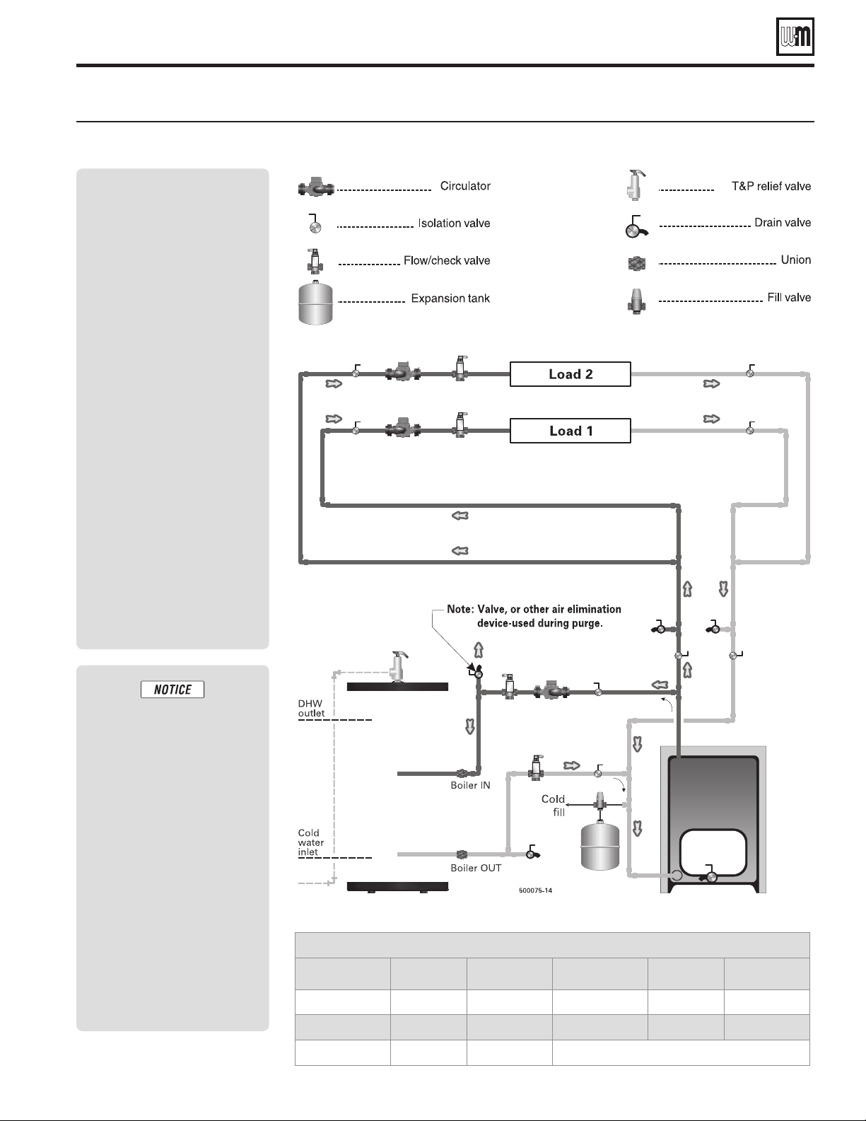
Figure 7 Zoning with circulators — direct-connected system piping
Notes
• Place circulators at beginnings of zones. Placing
them at the ends of zones
could result in heating idle
zones.
• Size manifold piping for
total flow of all zone circulators.
• Locate flow / check valves
as close as possible to water
heater boiler side connections — to reduce heat loss
between cycles.
Wiring
• WMCR zone controller,
optional priority — Figure 25, page 23.
1. This drawing is conceptual
only. It shows representative
piping components and layout. Weil-McLain does not
represent that this drawing
meets any particular mechanical or building codes.
The installer is responsible
for inclusion of all required
safety devices, or other miscellaneous piping hardware
not shown on drawing. The
installer is responsible for
proper sizing / select ion of
all hardware shown on this
diagram.
2. See boiler manual for spe-
cific details on installing the
boiler.
Part number 633-600-020/0118
Recommended flow rate and minimum boiler-side pipe size
Heater model GPM Pipe size Heater model GPM Pipe size
35
45
55
8 1”
8 1”
8 1”
85
105
Requires 1¼”x1” reducers at water heater
14 1¼” *
14 1¼” *
11
Page 12
AQUA PLUS® Series 2 indirect-fired water heaters — Product Manual
Boiler-side piping
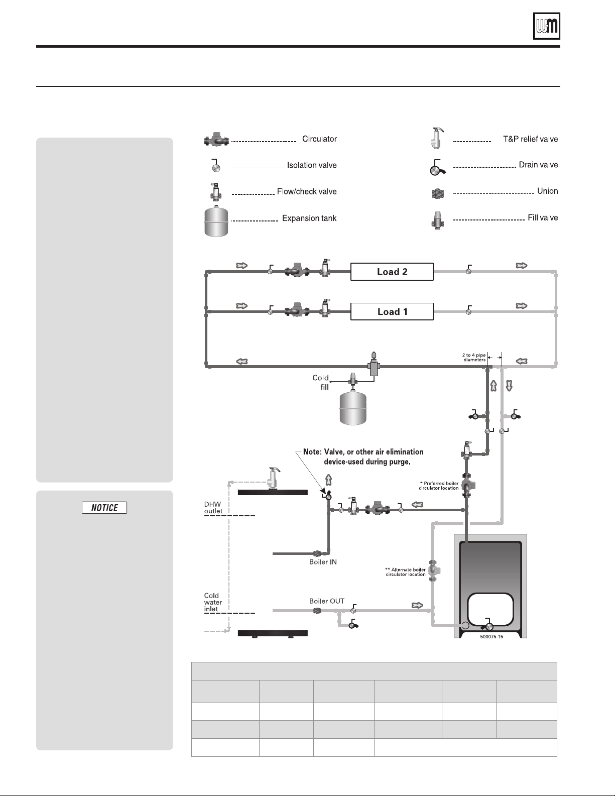
Figure 8 Zoning with circulators — primary/secondary system piping
Notes
• Place circulators at beginnings of zones. Placing
them at the ends of zones
could result in heating idle
zones.
• Size manifold piping for
total flow of all zone circulators.
• Locate flow / check valves
as close as possible to water
heater boiler side connections — to reduce heat loss
between cycles.
Wiring
• WMCR zone controller, optional priority —
Figure 25, page 23.
(continued)
1. This drawing is conceptual
only. It shows representative
piping components and layout. Weil-McLain does not
represent that this drawing
meets any particular mechanical or building codes.
The installer is responsible
for inclusion of all required
safety devices, or other miscellaneous piping hardware
not shown on drawing. The
installer is responsible for
proper sizing / select ion of
all hardware shown on this
diagram.
2. See boiler manual for spe-
cific details on installing the
boiler.
12
Recommended flow rate and minimum boiler-side pipe size
Heater model GPM Pipe size Heater model GPM Pipe size
35
45
55
8 1”
8 1”
8 1”
85
105
Requires 1¼”x1” reducers at water heater
14 1¼” *
14 1¼” *
Part number 633-600-020/0118
Page 13
AQUA PLUS® Series 2 indirect-fired water heaters — Product Manual
Boiler-side piping
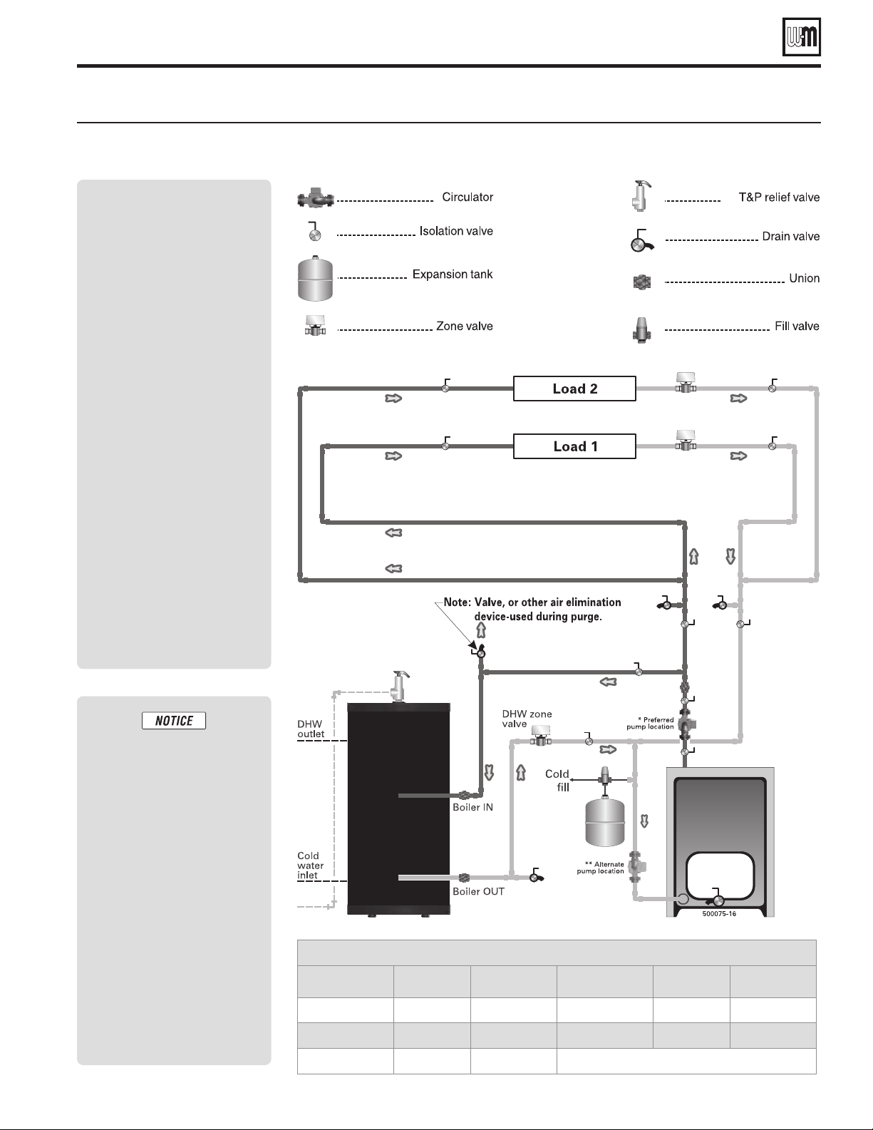
Figure 9 Zoning with zone valves — direct-connected system piping
Notes
• Place circulators at beginnings of zones. Placing
them at the ends of zones
could result in heating idle
zones.
• Size manifold piping for
total flow of all zone circulators.
• Locate flow / check valves
as close as possible to water
heater boiler side connections — to reduce heat loss
between cycles.
Wiring
• WMZV zone controller, optional priority —
Figure 26, page 23.
(continued)
1. This drawing is conceptual
only. It shows representative
piping components and layout. Weil-McLain does not
represent that this drawing
meets any particular mechanical or building codes.
The installer is responsible
for inclusion of all required
safety devices, or other miscellaneous piping hardware
not shown on drawing. The
installer is responsible for
proper sizing / select ion of
all hardware shown on this
diagram.
2. See boiler manual for spe-
cific details on installing the
boiler.
Part number 633-600-020/0118
Recommended flow rate and minimum boiler-side pipe size
Heater model GPM Pipe size Heater model GPM Pipe size
35
45
55
8 1”
8 1”
8 1”
85
105
Requires 1¼”x1” reducers at water heater
14 1¼” *
14 1¼” *
13
Page 14
AQUA PLUS® Series 2 indirect-fired water heaters — Product Manual
Boiler-side piping
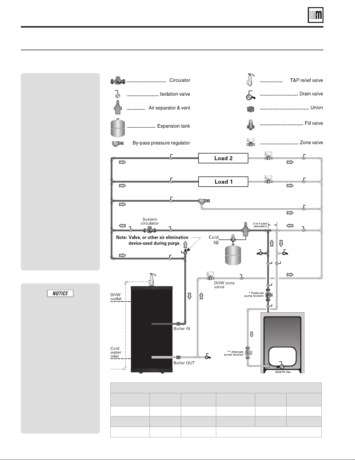
Figure 10 Zoning with zone valves — primary/secondary system piping
Notes
• Place circulators at beginnings of zones. Placing
them at the ends of zones
could result in heating idle
zones.
• Size primary piping for
total flow of all zone circulators.
• Locate flow / check valves
as close as possible to water
heater boiler side connections — to reduce heat loss
between cycles.
Wiring
• WMZV zone controller,
optional priority — Figure 26, page 23.
(continued)
1. This drawing is conceptual
only. It shows representative piping components
and layout. Weil-McLain
does not represent that this
drawing meets any particular mechanical or building codes. The installer is
responsible for inclusion
of all required safety devices, or other miscellaneous piping hardware not
shown on drawing. The
installer is responsible for
proper sizing / selection of
all hardware shown on this
diagram.
2. See Boiler Manual for specific details on installing
the boiler.
14
Recommended flow rate and minimum boiler-side pipe size
Heater model GPM Pipe size Heater model GPM Pipe size
35
45
55
8 1”
8 1”
8 1”
85
105
Requires 1¼”x1” reducers at water heater
14 1¼” *
14 1¼” *
Part number 633-600-020/0118
Page 15
AQUA PLUS® Series 2 indirect-fired water heaters — Product Manual
Boiler-side piping
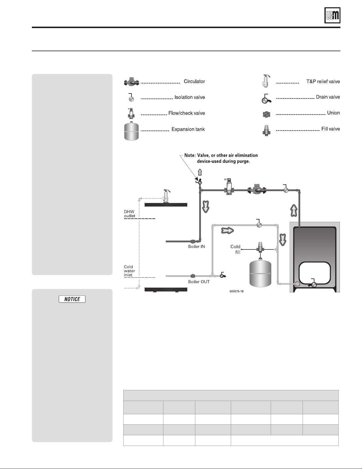
Figure 11 Dedicated single-boiler piping
Notes
• Place circulators at beginnings of zones. Placing
them at the ends of zones
could result in heating idle
zones.
• Size manifold piping for
total flow of all zone circulators.
• Locate flow / check valves
as close as possible to water
heater boiler side connections — to reduce heat loss
between cycles.
Wiring
• Connect water heater thermostat wires to boiler’s
T-T terminals or heat demand connection.
(continued)
1. This drawing is conceptual
only. It shows representative piping components
and layout. Weil-McLain
does not represent that this
drawing meets any particular mechanical or building codes. The installer is
responsible for inclusion
of all required safety devices, or other miscellaneous piping hardware not
shown on drawing. The
installer is responsible for
proper sizing / selection of
all hardware shown on this
diagram.
2. See boiler manual for specific details on installing
the boiler.
Part number 633-600-020/0118
Recommended flow rate and minimum boiler-side pipe size
Heater model GPM Pipe size Heater model GPM Pipe size
35
45
55
8 1”
8 1”
8 1”
85
105
Requires 1¼”x1” reducers at water heater
14 1¼” *
14 1¼” *
15
Page 16
AQUA PLUS® Series 2 indirect-fired water heaters — Product Manual
Boiler-side piping
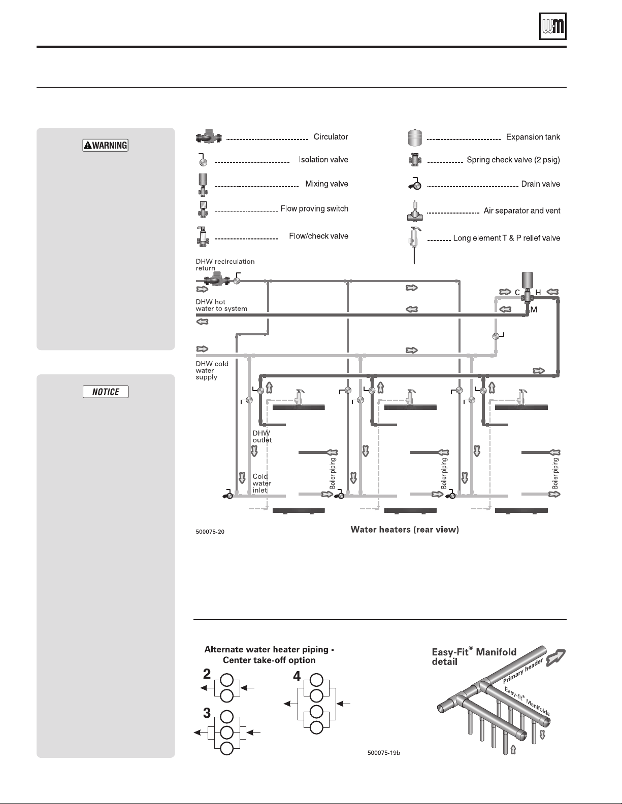
Figure 12 Multiple water heaters — domestic water piping
Failure to install automatic
mixing valve where recom-
mended can result in severe
personal injury or death.
(continued)
1. This drawing is conceptual
only. It shows representative
piping components and layout. Weil-McLain does not
represent that this drawing
meets any particular mechanical or building codes.
The installer is responsible
for inclusion of all required
safety devices, or other miscellaneous piping hardware
not shown on drawing. The
installer is responsible for
proper sizing / select ion of
all hardware shown on this
diagram.
2. Wire water heater thermostats in series when connecting to boiler controller
or boiler T-T terminals.
3. Install automatic mixing
valve at either the system
hot water connection or at
each water heater.
4. See page 8 through page 10
for additional recirculation
information and piping
details.
Figure 13 Alternate methods of revers-return piping and Easy-Fit® Manifold detail
16
Part number 633-600-020/0118
Page 17
AQUA PLUS® Series 2 indirect-fired water heaters — Product Manual
Boiler-side piping
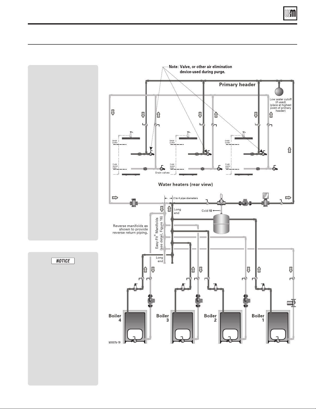
Figure 14 Multiple water heaters and dedicated multiple boilers — boiler water piping
Notes
• See legend and details in
Figure 12, page 16.
(continued)
1. This drawing is conceptual
only. It shows representative
piping components and layout. Weil-McLain does not
represent that this drawing
meets any particular mechanical or building codes.
The installer is responsible
for inclusion of all required
safety devices, or other miscellaneous piping hardware
not shown on drawing. The
installer is responsible for
proper sizing / select ion of
all hardware shown on this
diagram.
2. See boiler manual for spe-
cific details on installing the
boiler.
Part number 633-600-020/0118
17
Page 18
AQUA PLUS® Series 2 indirect-fired water heaters — Product Manual
Connecting to a low-pressure steam boiler
Special considerations
When designing steam and domestic hot water systems, there are some
key issues that must be taken into consideration during the initial design phase. By designing the system properly from the start, you can
avoid problems and have a hot water loop in a steam boiler system.
• The domestic water demand should preferably not exceed 1/3
of the steam boiler capacity. Larger demand may cause difficulty
obtaining steam as needed.
• Keep the loop temperature below the flash point. Flashing can result
in noise and circulator damage or shortened life.
• Be sure the loop is completely closed, with no automatic or manual
air vents, or anything that could allow air to enter the system when
the pump shuts off.
• Pipe supply from one side of the boiler, return to the opposite
side as shown.
• Supply from a tapping that is high enough to prevent introducing
sediment into the piping and circulator yet still below the water
line. Avoid the mud leg of the boiler.
• Use an all bronze circulator.
• Avoid wet rotor circulators. Select a circulator with a large
volute, such as a typical 3-piece circulator.
• This will reduce clogging and will resist the corrosion potential
from the steam condensate.
• Make sure the circulator is properly sized. If the circulator runs too
far out on its curve, cavitation potential increases significantly.
• Use (2) flow / check valves as shown to reduce the potential for
gravity circulation.
• DO NOT use spring-loaded check valves in place of the
flow / check valves shown in Figure 16, page 19.
Installation and start-up of water heaters
connected to steam boilers
1. See Figure 16, page 19, for suggested piping schematic.
2. Pipe the domestic water connections to the water heater per “Domestic water piping,” page 6.
Boiler connections for the water heater must be below
the water line. DO NOT use the gauge glass tapping or a
low water cut-off tapping if a LWCO is installed there.
For steam piping, refer to the steam boiler manual.
DO NOT install an air vent anywhere in the piping. The
piping must be air tight.
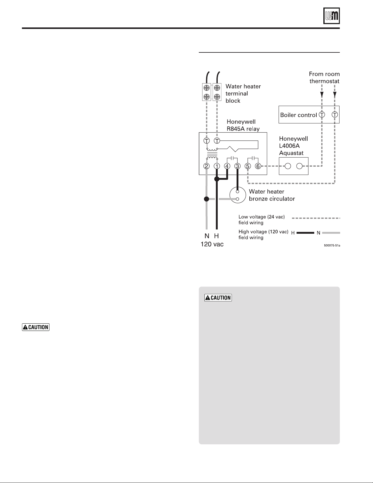
3. Wire the water heater and circulator to the boiler per suggested
wiring in Figure 15. The water heater must be wired and ready to
operate before proceeding. Note that the L4006A aquastat is located
in the boiler and sets a boiler operating temperature when there is
no call for steam heating.
To fill the boiler and water heater:
1. Follow the procedure given in Figure 16, page 19 to fill the water
heater piping.
2. Follow the boiler manual instructions to fill the steam boiler.
Figure 15 Typical wiring for connection to low-
pressure steam boiler
Install the Honeywell L4006A aquastat in the boiler,
below the water line. Set for a temperature of 180 to
190°F to control boiler temperature when there is no
call for steam heating.
Valve 7, the memory stop valve, must
be supplied, piped and adjusted as instructed. This valve allows cooler return
water to mix with the hot water from
the steam boiler. The valve is set to yield
approximately 180°F water entering the
circulator. Higher temperature water
could cause cavitation in the circulator,
damaging the impeller and shortening
circulator life.
DO NOT connect the piping to the boil-
er’s mud leg. This would probably cause
excessive sediment to enter the water
heater piping, damaging the circulator.
The strainer in the circulator suction line
must be serviced regularly. NOTE that
noise from the circulator is a likely sign
that the strainer is restricting circulator
flow, causing cavitation.
18
Part number 633-600-020/0118
Page 19
AQUA PLUS® Series 2 indirect-fired water heaters — Product Manual
Connecting to a low-pressure steam boiler
(continued)
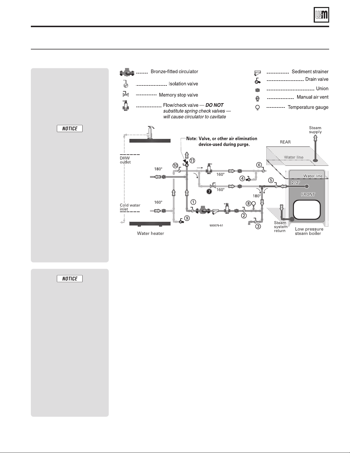
Figure 16 Low pressure steam boiler application — Domestic water heating using water pumped from steam boiler
Notes
• Locate flow / check valve as
close as possible to water
heater boiler side connections — to reduce heat loss
between cycles.
Use memory stop valve 7 to
blend some of the water returning to the boiler with the
hot water coming from the
boiler. This will reduce the
possibility of flashing (cavitation) in the circulator. Slowly
open valve 7 until temperature
gauge 8 reads 200°F.
Set the memory stop on valve 7
after adjusting. Attach a tag to
the valve warning not to close
or change valve position.
NOTE — If the boiler water
level should drop below either the water heater boiler
water supply or return line,
the filling procedure will
have to be repeated.
1. This drawing is conceptual
only. It shows representative
piping components and layout. Weil-McLain does not
represent that this drawing
meets any particular mechanical or building codes.
The installer is responsible
for inclusion of all required
safety devices, or other miscellaneous piping hardware
not shown on drawing. The
installer is responsible for
proper sizing / select ion of
all hardware shown on this
diagram.
2. See boiler manual for spe-
cific details on installing the
boiler.
Filling the piping
1. Parts of the boiler water piping to the
water heater may be higher than the water line, depending on the height of the
water heater boiler supply connection.
The piping must be air tight to prevent air
from pocketing at the top of the piping,
stopping flow.
2. The boiler MUST be filled and ready to
operate before proceeding. Follow the
boiler manual to fill the boiler.
3. Follow the procedure below to fill the
boiler-to-water heater piping. See Figure 16.
Step 1 Close isolation valves 5 and 6 to isolate
the boiler.
Step 2 Close valve 3 and open valve 4. Con-
nect a cold water supply hose to
valve 3. Connect a hose from valve 4
to a drainable location.
Step 3 Close valve 10. Open valve 7.
Step 4 Open valve 3. Water will flow through
valve 7 and out through valve 4 to
drain. Open valve 11. Let water run
until all air has been removed from
the line through valve 11. Close valve
11. Close valve 4. Then close valve 3.
Step 5 Close valve 7. Then open valve 10.
Step 6 Open valve 3. Water will flow through
the circulator line, the water heater
coil and the return piping, then out
through valve 4 to drain. Let water run
until all air has been removed from the
line. Close valve 4. Then close valve 3.
Remove hoses.
Step 7 Follow the instructions in “Water
heater filling and start-up,” page 26,
to fill the domestic water side of the
water heater.
Step 8 Open valve 7 about ¼ turn for an
initial setting.
Step 9 Open isolation valves 5 and 6. Make
sure the boiler water level is correct
per the boiler manual.
Step 10 Start the boiler per instructions given
in the boiler manual. Allow boiler to
begin steaming.
Step 11 Start the DHW circulator. Watch the
temperature at gauge 8. Adjust valve 7
until gauge 8 reads about 180°F with
system at steady operation.
Step 12 Continue checking under varying
DHW demand conditions to ensure
system will operate as required.
Part number 633-600-020/0118
19
Page 20
AQUA PLUS® Series 2 indirect-fired water heaters — Product Manual
24 VAC
Input
To
Boil er
Cont rol
AcuTemp
2000WM
thermostat
AquaBalance boiler
Control terminals
500075-60
Boiler-side wiring and controls
Electrical shock hazard — Can cause severe
personal injury, death or substantial property
damage. Disconnect power before installing
and / or servicing.
Wiring requirements
1. All wiring must be a minimum of 18 gauge and installed
in accordance with:
• U.S.A. — National Electrical Code and any other
national, state or local code requirements having jurisdiction.
• Canada — CSA C22.1 Canadian Electrical Code Part
1 and any other national, provincial and local code
requirements having jurisdiction.
2. If original wire as supplied with appliance must be replaced,
Type 90° C or its equivalent must be used.
3. Refer to control component instructions packed with boiler
for application information.
4. An optional service switch may be installed in water heater
electrical circuit. This switch would only shut off the water
heater, not the home heating system. Do not shut off water
heater if there is a chance of freezing.
5. All electrical contacts are shown with no power applied —
off-the-shelf condition.
Figure 17 Wiring the control “General Connection”
Circulators
Size priority relay for total amp draw of all circulators.
Zone Valves
Size transformer for maximum load of all zone valves.
Wiring to the water heater
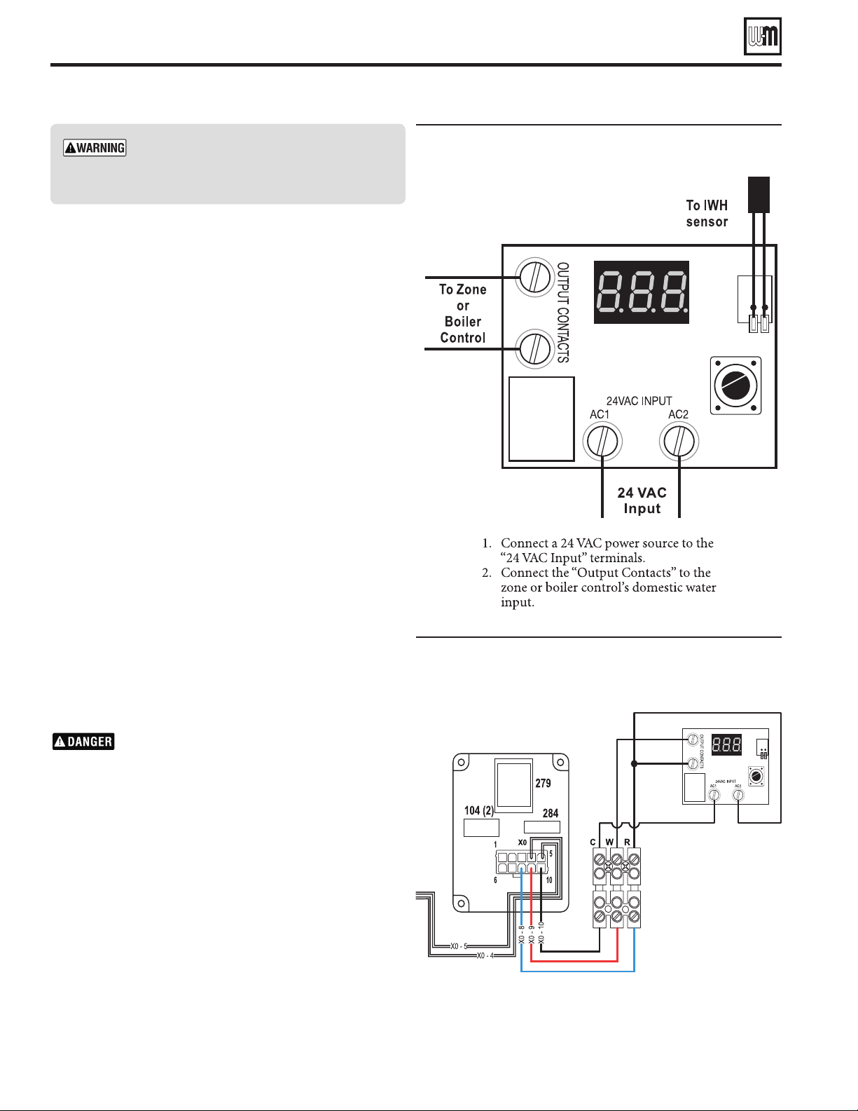
1. Field connections to the water heater thermostat are for
24 VAC only, connecting to the two-pole terminal block
shown in Figure 17.
Hot Water Can Scald – Connecting to greater
than a 24 volt circuit will cause hot water that can
cause severe personal injury.
Wiring options
1. This manual shows wiring only for use of Weil-McLain
WMCR Circulator Zone Controller or Weil-McLain
WMZV Zone Valve Zone Controller.
2. Other wiring methods may be acceptable and are left to
the installer.
Use domestic priority
1. When possible, set controls to provide domestic priority
— that is, on a call for domestic water the control switches
from space heating to DHW only.
2. Domestic priority ensures the fastest possible response to
the DHW call for heat.
3. The smaller the water heater, the greater the need for rapid
response.
Figure 18 Wiring the control to the AquaBalance
controls will connect to the AcuTemp 2000 WM
thermostat.
TM
boiler
20
Part number 633-600-020/0118
Page 21
AQUA PLUS® Series 2 indirect-fired water heaters — Product Manual
2
1
1
2
3
4
5
1
2
3
4
Additional limits if used
(Will require manual reset)
Additional limits if used
(Control will automatically
reset)
P13
P11
P10
P12
Display/interface
panel
Flue temp.
sensor
Heat exchanger
outlet temp.
sensor
Red
Orange
Gray
Black
Factory jumpers (remove if using limits)
Outdoor temp. sensor
(if used)
Low water cutoff (if used)
AcuTemp
2000WM
thermostat
ECO boiler
Control terminals
500075-62
24 VAC
Input
To Zone
or
Boiler
Contro l
For replacement order part number 381-330-020
Control Part Number 511-330-279
WARNING
EXPLOSION HA ZARD
CAN CAUSE SER IOUS INJU RY OR DEATH
This device can malfunction if it
gets wet. Never attempt to use
this device if it has been wet –
REPLACE IT !
NOTICE
Please refer to boiler manual for wiring instructions. Use copper
conductor only suitable for a minimum 105° C wire or equivalent.
CAUTION
Risk of ELECTRI CAL SHOCK - more than one disconnect
switch maybe required to de-energize the device for servicing.
White
P10
P9
P13
P11
P12
P14
P15
P16
P8
REMOTE
SENSE
AcuTemp
2000WM
thermostat
Evergreen boiler
Control terminals
500075-63
2
1
1
2
3
4
5
1
2
3
4
1
2
3
1
2
3
4
5
6
P15
P14
P13
P11
P10
P12
Red
Blue
Orange
Gray
Black
Common
Factory jumpers (remove if using limits)
Boiler-to Boiler Out
(multiple boilers only)
Boiler-to Boiler In
(multiple boilers only)
Fuse
3-amp
120vac
Y Y
BL
W
R
R
W
W
R
80
60
70
80
70
60
80
60
70
80
70
60
_
+
24 VAC
Input
To Zone
or
Boiler
Contro l
Boiler-side wiring and controls
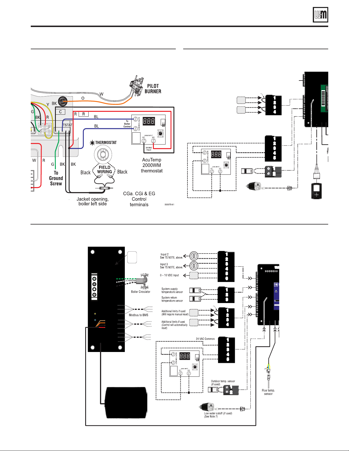
Figure 19 Wiring the control to the CGa (1135-05/606),
CGi (1135-615), and the EG Water (1135-605)
boiler controls will connect to the AcuTemp
2000WM thermostat.
Figure 20 Wiring the control to the ECO (1176-120/121)
boiler controls will connect to the AcuTemp
2000WM thermostat.
(continued)
Figure 21 Wiring the control to the Evergreen (1176-160) and SlimFit 550-750 (1176-170) boiler controls will connect to
the AcuTemp 2000WM thermostat.
Part number 633-600-020/0118
21
Page 22
AQUA PLUS® Series 2 indirect-fired water heaters — Product Manual
To thermostat
Air pressure
switch
500075-64
White
hose
Red
hose
BK
AcuTemp
2000WM
thermostat
GV90+ boiler
Control terminals
BL
BL
R
24 VAC
Input
To
Boil er
Cont rol
BL
C
R
To
Ground
Screw
P16
WH
Y
1234567 1234567
2
1
1
2
3
4
5
1
2
3
4
1
2
3
1
2
3
4
5
6
120V
Call for heat demand 2
(Default for thermostat)
Call for heat demand 3.
Modulating input
(0 – 10 VDC)
System supply
temperature sensor
Additional limits if used
(Will require manual reset)
Additional limits if used
(Control will automatically
reset)
Low water cutoff (if used)
P15
P14
P13
P11
P10
P12
80
60
70
80
70
60
80
60
70
80
70
60
Display/interface
panel
Flue temp.
sensor
Heat exchanger
outlet temp.
sensor
Heat exchanger
inlet temp.
sensor
Gas
valve
Red
Blue
Orange
Gray
Black
White
16-pin
connector
(through
cabinet)
Common
P3
24V
Factory jumpers (remove if using limits)
System return
temperature sensor
AcuTemp
2000WM thermostat
Ultra boiler
Control terminals
500075-66
24 VAC
Input
To Zone
or
Boiler
Contro l
Boiler-side wiring and controls
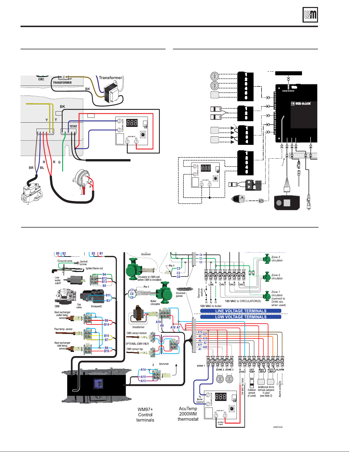
Figure 22 Wiring the control to the GV90+ (1135-700)
boiler controls will connect to the AcuTemp
2000WM thermostat.
Figure 24 Wiring the control to the Ultra (1176-100) boiler
controls will connect to the AcuTemp 2000WM
thermostat.
(continued)
Figure 23 Wiring the control to the WM97+ (1176-112/113) boiler controls will connect to the AcuTemp 2000WM
thermostat.
Part number 633-600-020/0118
22
Page 23
AQUA PLUS® Series 2 indirect-fired water heaters — Product Manual
50075-40
24 VAC
Input
To Zone
or
Boiler
Control
Thermostats
Circulators
Priority
circulator
120VAC
Hot
Neutral
Grd
Control Port
Electronic
Fuse
WMCR-4
Circulator Zone
Controller
Weil-McLain
Michigan City, IN
120 VAC Circulators
Priority Zone
Zone 2
Zone 3
Zone 4
120 VAC IN
Isolated
Switch
Priority ON
Priority ON
X–X
ZR/ZC
Zone 1
THERMOSTATS
1234
1
234
Zone 2 Zone 3
Zone 4
Zone 2 Zone 3 Zone 4
Common
24 V
@ 1 VA
To Expansion
Module
OUT
LX
ZC
ZR
XN
LN
LLLNNN
T
W
T
W
T
W
T
W
T
R
T
R
T
R
T
R
To boiler T–T
Water Heater
AcuTemp
2000WM thermostat
Boiler-side wiring and controls
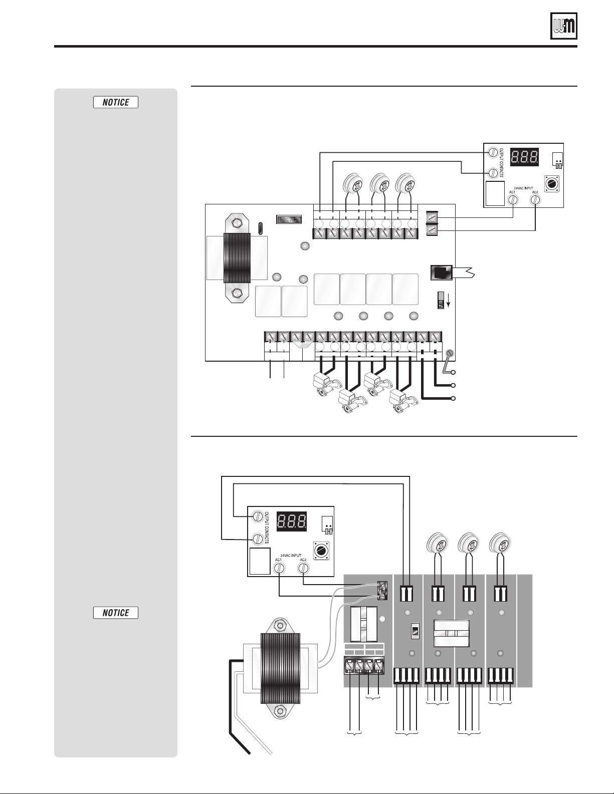
Figure 25 Typical wiring — zoning with circulators — DHW priority with Weil-McLain
WMCR Circulator Zone Controller
1. These drawings are concep-
tual only. It shows representative components and
wiring. Weil-McLain does
not represent that these
drawings meets any particular mechanical or building codes. The installer is
responsible for inclusion of
all required safety devices,
or other miscellaneous piping hardware not shown
on drawing. The installer
is responsible for proper
sizing / selection of all hardware shown on this diagram.
2. Follow component manufacturer’s instructions for
installation of all items
shown.
3. See boiler manual for specific details on installing the
boiler.
System piping
• Figure 7, page 11
• Figure 8, page 12
(continued)
Notes
• Also refer to the WMZV
manual and Weil-McLain
Boiler Zone Wiring
Guide for further details.
• Refer to Wiring requirements on page 20.
System piping
• Figure 9, page 13
• Figure 10, page 14
Install all zone valves per
valve manufacturer’s instructions.
Part number 633-600-020/0118
Figure 26 Typical wiring — zoning with zone valves — DHW priority with Weil-McLain
WMZV Zone Valve Zone Controller
AcuTemp
To Zone
or
Boiler
Control
Connect 120VAC
power leads to
transformer black
and white leads.
2000WM thermostat
24 VAC
Input
To circulator
or boilerT–T
terminals
24 VAC
COM
24 VACEND SW 1
24 VAC
constant
to 5-wire
zone
valves
Thermostat
zone 2
Thermostat
zone 3
T T
X-X
ON
55XX
ON
Priority
zone
switch
OFF
1234 1234 1234 1234
To zone 2
zone valve
To priority
zone valve
Zone 3Zone 2Priority
To zone 3
zone valve
Thermostat
zone 4
T TT TT T
Zone 4
To zone 4
zone valve
50075-41
Zone Valve Controller
WMZV-4
Weil-McLain
Michigan City, IN
23
Page 24
AQUA PLUS® Series 2 indirect-fired water heaters — Product Manual
Mounting and wiring the Control - New Installations
1. Locate the sensor leads on the top of the tank.
2. Route the sensor wire through the opening in
the rear of the control.
4. Insert the sensor wire into the channel in the
back of the control.
5. Attach the control to the top plastic cap of the
tank and secure with two (2) screws.
3. Plug the AquaPlus sensor wire into the sensor
input. The terminals are not polarity sensitive.
Refer to “Boiler-side wiring and controls” on pages 20 - 23 for wiring instructions.
24
6. Add a third screw through the top of the control. Reinstall control cover once wiring connections are made and the control is mounted.
Part number 633-600-020/0118
Page 25
AQUA PLUS® Series 2 indirect-fired water heaters — Product Manual
Setting the Thermostat Control
1 Display.
During normal operation, one of two indicating lights will appear on the display. If
the control is calling for heat, the indicating light on the bottom right of the screen
will illuminate. When the water temperature reaches the control set point, the indicating light on the left of the display will illuminate indicating that the tank is up to
temperature and the control is in Standby.
2 Setting the control.
Push the setting dial to enter the Temperature Setting mode. When pressed, the
display will show ‘OFF’ or the current temperature setting. Turn the dial to select
the desired water temperature to be maintained in the water heater. See Commercial/Residential (below) for available temperature ranges. The display will
return to the operating mode (see Display above) after five seconds of inactivity.
IMPORTANT: Temperature variations can exist within the water heater. The
value displayed on the control is the approximate temperature. A typical starting adjustment point is 120°F. Test the water at the closest point of use for final
control adjustment.
Scald Hazard – Exposure to 125°F or hotter water
can cause scalding injuries. A mixing valve should be
installed on installations set at 125°F or higher.
Calling for Heat Standby
Water temperature over 125°F (52°C) can
cause severe burns instantly resulting in
severe injury or death.
Children, the elderly, and the physically or
mentally disabled are at highest risk for
scald injury.
Feel water before bathing or showering.
Temperature limiting valves are available.
Read instruction manual for safe tem-
perature setting.
3 Setting the Temperature / Differential.
The differential does not need to be set. The thermostat’s advanced software algorithm determines the optimum temperature
to initiate heat calls.
4 Celsius / Fahrenheit.
To change from Fahrenheit to Celsius, push and hold the setting dial for 5 seconds. The current selection, “F” or “c” will blink
on the LED display. Release and turn the setting dial to the desired setting “F” or “c” then push the setting dial again to select it.
When the control is set for Celsius, the display will include a “c” following the temperature. Once selected, the
display will return to the current water temperature.
5 Residential / Commercial.
The control is equipped with two temperature ranges: One for residential installations (60°F-160°F) and a second for commercial
installations (60°F-180°F). To change from the Residential range to the Commercial range, remove power from the control. Then
push and hold the setting dial while restoring power. The current range, “r” or “c” will blink in the LED display. Release and turn
the setting dial to the desired range “r” or “c”, then push the setting dial again to enter the setting. Once entered, the display will
briefly show the selected setting; then the control will display “off ”. Follow the instructions above (Setting the Control) to set the
desired temperature within the selected (residential or commercial) range.
6 Error Codes.
Sensor Error The resistance value of the sensor is out of range. Check the sensor connection to the pc board.
If the connection is good, the sensor may need to be replaced.
Self Test Error The control has failed an internal test of the hardware or software. Try cycling 24 VAC power
off and on. If the problem is resolved, the control will return to normal operation. If the error
does not clear, the control should be replaced.
Part number 633-600-020/0118
25
Page 26

AQUA PLUS® Series 2 indirect-fired water heaters — Product Manual
Water heater filling and start-up
The installation and water chemistry must meet
the requirements below. Failure to comply could
result in damage to the water heater, causing possible severe personal injury, death or substantial
property damage.
Boiler water restrictions
• Thoroughly flush the boiler system (without water heater
connected) to remove sediment.
• The water heater heat exchanger can be damaged by build-up
or corrosion due to sediment.
• Boiler water (including additives) must be practically nontoxic, having toxicity rating or class of 1, as listed in Clinical
Toxicology of Commercial Products.
• If antifreeze is used in boiler system:
• Local codes may require a backflow preventer on cold
water supply line.
• Use antifreeze specifically intended for hydronic heating
systems. Inhibited propylene glycol is recommended.
• Follow boiler manual instructions for antifreeze usage.
• Do not use automotive, ethylene glycol or petroleum-
based antifreeze. Do not use any undiluted antifreeze.
Maximum boiler-side flow rate
• Select the boiler-side circulator carefully. The flow rate
through the boiler side of the water heater must not exceed
the values below. Higher flow rates could result in an input
above the rating of the T&P valve.
• Models AQ UA PLUS
• Models A QU A PLUS
®
-32, 42 and 52 - do not exceed 12 GPM.
®
-80 and 105 - do not exceed 16 GPM.
Start-up checklist
Verify that T&P relief valve is properly installed and
piped as directed in this manual and per local code
requirements.
Verify that the DHW tank and boiler-side piping are
complete and are filled with water and pressurized.
Verify that all air has been bled from both domestic and
boiler water systems.
Verify that cold and hot water lines are correctly con-
nected to domestic water system.
Verify that supply and return piping from boiler is cor-
rectly connected to water heater.
Check all fittings and piping for leaks.
Verify that all wiring is installed correctly.
Set water heater thermostat according to system require-
ments. See “Water heater temperature adjustment,”
page 27.
Start boiler according to the Boiler Manual.
Verify that the boiler and water heater are operating
correctly, per “Water heater temperature adjustment,”
page 27.
Review the following sections with the homeowner or
system operator:
Filling the domestic water tank
1. Fill the domestic water tank with fresh water that meets the chemistry requirements above.
2. Do not exceed a fill pressure of 70 PSIG.
When the water supply pressure is higher than 70 PSIG,
make sure that a pressure-reducing valve is installed on
the cold water supply line to prevent leakage from the T&P
relief valve. A thermal expansion tank is also required.
3. Vent the piping as necessary to remove any trapped air.
Start-up and operation
1. Follow the “Start-up checklist,” page 26 to prepare for start-up.
26
• Water Heater Start-Up
• Adjusting Water Heater Temperature
• Water Heater Maintenance
Part number 633-600-020/0118
Page 27
AQUA PLUS® Series 2 indirect-fired water heaters — Product Manual
Water heater temperature adjustment
General notes
• Household water usage patterns will affect water temperature at
any faucet or shower.
• Occasionally check temperature at each point of use, then
adjust thermostat accordingly.
• Always recheck temperature after adjusting thermostat.
• When hot water is used in repeated small quantities, a “stacking”
effect can develop in hot water tank. The upper layer of water in
tank can be much hotter than lower layers.
• Lowering the thermostat setting or installing automatic mixing
valves as indicated in these instructions will reduce water temperature levels. Consult your installer or service technician.
At no time should boiler limit control be set above 200°F.
This can cause severe personal injury, death or substantial
property damage if ignored.
Studies have indicated that dangerous bacteria, includ-
ing
legionella pneumophila, can form in the potable
water distribution system if certain minimum water
temperatures are not maintained. Contact your local
health department for more information.
Hot Water Can Scald!
Setting the thermostat
1. The water heater thermostat is factory set to its lowest temperature.
This may or may not be suitable for your needs.
2. Turn thermostat knob clockwise to increase water temperature.
3. Turn thermostat knob counter-clockwise to reduce water
temperature.
4. When decreasing temperature setting, the stored hot water must
be drawn off before checking temperature at faucet.
5. Check water temperature at a hot water faucet immediately after
first heating cycle. Further temperature adjustment may be necessary as water heating system is used. Recheck water temperature
at faucet after adjustment.
6. When adjusting thermostat, be sure boiler limit control is set a
minimum 20°F higher.
7. See information packed with thermostat for more instructions.
Figure 27 Water heater digital temperature control
• Water heated to temperature for clothes washing,
dish washing and other sanitizing needs can scald
and cause permanent injury.
• Children, elderly, and infirm or physically handicapped persons are more likely to be permanently
injured by hot water. Never leave them unattended
in bathtub or shower. Never allow small children to
use a hot water tap or draw their own bath.
• If anyone using hot water in the building fits
the above description, or if state laws or local
codes require certain water temperatures at
hot water taps, you must take special precautions:
• Use lowest possible temperature setting.
• Install some type of tempering device,
such as an automatic mixing valve, at
hot water tap or water heater. Automatic
mixing valve must be selected and installed
according to valve manufacturer’s recommendations and instructions.
• Water passing out of drain valves may be extremely
hot. To avoid injury:
• Make sure all connections are tight.
• Direct water flow away from any person.
Part number 633-600-020/0118
Protection must be taken against excessive temperature and pressure! — Installation of a temperature & pressure (T&P) relief valve (provided
with water heater) and a thermostatic mixing valve
(provided by installer) is required.
27
Page 28
AQUA PLUS® Series 2 indirect-fired water heaters — Product Manual
Water heater maintenance
Boiler water — read and comply with all requirements
under “Boiler water restrictions,” page 3.
Water from opened drain valves, unions and other
connections may be extremely hot. To avoid severe
personal injury, death or substantial property damage:
• Tighten all drain hose connections.
• Direct hot water away from all persons.
ATTENTION USER!
Have the water heater serviced at least once
annually
Follow the maintenance procedures below at least
monthly.
Read “Water heater temperature adjustment,”
page 27.
Failure to comply with the above can result in se-
vere personal injury, death or substantial property
damage.
by a qualified service technician.
MONTHLY maintenance by user
• At least MONTHLY, visually check valves, pipes and fittings
for leaks.
• Check hot water supply at several outlets. Make sure water
temperature is not too hot.
• Call qualified service technician to repair leaks or address
problems.
MONTHLY maintenance by user
• At least MONTHLY, visually check valves, pipes and fittings for
leaks.
• Check hot water supply at several outlets. Make sure water temperature is not too hot.
• Call qualified service technician to repair leaks or address problems.
ANNUAL start-up by qualified service
technician
Obtain an Inspection and service kit (see “Replacement
parts,” page 38) before attempting to perform the annual start-up. This kit contains items that will usually
have to be replaced.
Check water supply temperature at several outlets
to ensure the water temperature is acceptable for
intended use and that all temperature control devices
are functioning properly. Read page 3 and verify that
all requirements are met by the installation.
Perform the following procedures:
Perform any procedures required by local codes.
Verify system pressure both on domestic water and boiler water
sides.
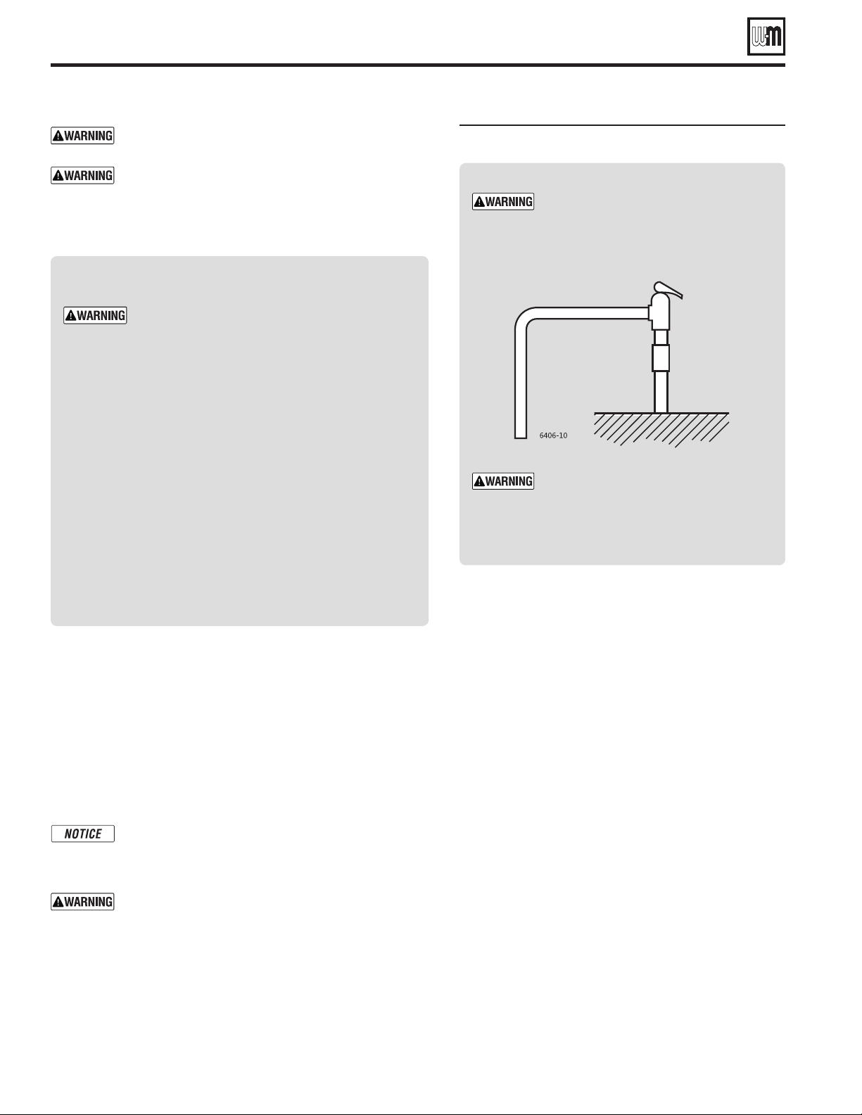
Figure 28 T&P valve operation
Before operating the T&P relief valve,
make sure no one is in front of or around
the T&P relief valve discharge piping. Hot
discharge water can cause severe personal
injury or substantial property damage.
Plugging T&P relief valve or discharge
piping can cause excessive pressure in the
water heater, resulting in severe personal
injury, death or substantial property damage.
Manually operate T&P relief valve at least once a year (see
Figure 28). This will release some hot water. Move operating lever to open position for a few seconds and then move
it back, allowing it to snap closed. After T&P relief valve is
operated, if it continues to release water, close cold water
inlet to water heater immediately. Follow draining instructions, and replace the T&P relief valve. If T&P relief valve
weeps periodically, it may be due to thermal expansion.
Install an expansion tank if not already installed.
Follow instructions on circulator to oil it, if oil-lubricated.
Check valves, pipes and fittings for leaks.
Check function of all controls and valves (see control
manufacturer’s instructions).
Review homeowner’s maintenance responsibilities and
their frequencies, including any not listed in the following paragraphs.
Drain the water heater if necessary
during shutdown periods
1. Drain the water heater if it will be shut off and exposed
to freezing temperatures. Freezing water will expand and
may damage water heater.
a. If boiler water contains sufficient antifreeze, then only
the domestic water needs to be drained.
b. If boiler water does not contain sufficient antifreeze,
then the boiler water and the domestic water must
be drained.
28
Part number 633-600-020/0118
Page 29

AQUA PLUS® Series 2 indirect-fired water heaters — Product Manual
Troubleshooting
Troubleshooting procedures
Follow the troubleshooting guidelines step by step. Always double-check your results. Skip-
ping or not completing steps can lead to wrong conclusions, repeated callbacks to the job site and
unhappy customers.
Preparation for troubleshooting
Tools needed
Electrical meter to measure voltage and continuity.
Pressure gauge (such as Watts #276H300 test gauge).
Temperature gauge.
Stopwatch.
Bucket — 1 gallon or larger, with volume markings.
Suggested parts to have on hand.
Tank thermostat (Thermostat) — see Replacement parts for part number.
Inspection and service kit — see Replacement parts for part number.
Information needed before the service call
Know the water heater model number.
Know the boiler manufacturer and model number.
Have the boiler manual and wiring and piping schematics readily available.
Get the latest revisions from www.Weil-McLain.com.
Review all manuals before leaving for the job site.
Part number 633-600-020/0118
29
Page 30
AQUA PLUS® Series 2 indirect-fired water heaters — Product Manual
Troubleshooting
Figure 29 Typical problems and causes and page location for details
Problem Check possible causes Page
Insufficient
hot water
Excessive
domestic water
temperature
Boiler relief valve
lifting or weeping
(continued)
1 Undersized water heater?
2 Boiler system improperly sized?
3 Check component parts.
4 Check boiler operating tempera-
tures.
1 Reduce stacking
• Lower boiler operating temperature.
1 Undersized expansion tank?
2 Faulty boiler expansion tank?
3 Faulty boiler relief valve?
5 Check location of flow control
devices.
6 Check for air in the system.
7 Clean the boiler water system.
8 Check tank thermostat setting.
2 Install a thermostatic mixing valve.
3 Install a recirculation loop.
4 Faulty boiler fill valve?
31
33
33
Temperature/
pressure relief
valve lifting
or weeping
Water on the
floor near the
tank
Top of tank or
insulation wet
Water quality
problems
1 Undersized or missing domestic
water side expansion tank?
2 Faulty domestic water side expan-
sion tank?
3 Faulty T & P relief valve?
1 Check for leaks from sources other
than the water heater.
1 Check for leaks from sources other
than the water heater.
1 Water smells like “rotten eggs.”
2 Milky water.
4 High domestic water supply pres-
sure?
5 Possible water hammering or pres-
sure spikes?
6 Check boiler operating tempera-
ture.
2 T & P relief valve lifting and dis-
charging?
3 Loose piping connections?
2 Loose piping connections?
3 Discolored water from the hot
water faucet.
35
35
36
36
30
Part number 633-600-020/0118
Page 31

AQUA PLUS® Series 2 indirect-fired water heaters — Product Manual
Troubleshooting
Troubleshooting
(continued)
(continued)
Insufficient hot water
7 Undersized water heater?
• There are many methods of sizing various applications, i.e. ASHRAE sizing tables or ASPE domestic water heating design
manual.
• Confirm the water demand required for the application.
• Confirm the flow rates of the fixtures.
• For example, was the tank sized for shower heads at 2.0 gpm, while the actual heads are 5.0 gpm?
• Use a bucket and a stopwatch to determine fixture flow rates.
• Evaluate the hot water usage pattern for a day.
• Is the peak demand unusually high for the application?
• Has the demand for domestic hot water changed since the system was installed?
• A bathroom remodeling project with a newly installed whirlpool tub will substantially change the domestic water demand.
8 Boiler system improperly sized?
• Can the boiler provide the required output to meet the domestic water load? Determine the boiler domestic water capacity,
GPH, by the following:
Boiler DHW capacity, GPH =
[Temp. rise °F = Required DHW temp. °F – Incoming temp. °F]
[8.33 = Density of water (lbs/gal) x 1 Btu / lb-°F]
• Example — A single family home with a 3.0 GPM shower fixture and a 150,000 Btuh output boiler capacity.
• The shower demand of 3.0 GPM equals 180 GPH (60 times the GPM).
• Is the boiler capacity enough to deliver this hot water flow at 115°F for an extended period? Determine the boiler capacity:
Boiler DHW capacity, GPH =
(115°F – 50°F) x 8.33
• The boiler is capable of delivering 277 GPH (or 4.6 GPM) continuously, which is enough for this application.
• Measure the BTU input to the boiler by clocking the gas meter or finding the oil flow rate based on nozzle size and pump
pressure.
• Does the hot water system need to be wired for domestic priority? For systems in which either the storage or BTU’s available
are marginal it is recommended to wire the domestic water heater in a priority manner.
• Is the boiler piping to the water heater properly sized to allow the required flow rate for maximum BTU transfer? The temperature differential of the boiler supply and return water should be 20°F to 30°F.
• Is the circulator between the boiler and the water heater properly sized to provide enough flow for maximum BTU transfer?
Check the table below:
Boiler output Btuh
Temp. rise °F x 8.33
150,000 Btuh
= 277 GPH
Part number 633-600-020/0118
Pipe size Flow, GPM MBH Pipe size Flow, GPM MBH
¾” 1 to 4 50 to 100 1 ½” 14 to 22 200 to 450
1” 4 to 8 100 to 180 2” 22 to 45 300 to 650
1 ¼” 8 to 14 160 to 300
31
Page 32

AQUA PLUS® Series 2 indirect-fired water heaters — Product Manual
Troubleshooting
(continued)
Insufficient hot water (continued)
9 Check component parts.
• Is the domestic water thermostat functioning properly?
• Check the water heater thermostat (requires an electrical meter).
1. Disconnect the field wiring to the water heater thermostat terminals.
2. Turn the thermostat knob to the highest setting — clockwise — to initiate a call for heat.
3. Check for continuity across the water heater thermostat terminals. On a call for heat, these contacts should closed.
4. Continue checking for continuity while turning the thermostat knob to the lowest setting — counter clockwise — to
satisfy the call for heat. The contacts should open, breaking the continuity.
5. If any of these steps fail, replace the thermostat.
• Is the thermostat setting too low?
• If the thermostat setting is too low, the boiler may not have the opportunity to deliver the maximum BTU’s required to
completely heat the entire volume of water stored in the tank.
• During a call for heat by the water heater, does the boiler circulator begin pumping, does the zone valve open, does the boiler
fire? Check every component in the system to ensure they are properly functioning.
10 Check boiler operating temperatures.
• If possible, increase the boiler operating temperature to 180°F or 200°F.
• Maintain a minimal temperature in the boiler during non-heating seasons.
• A boiler typically has a higher standby loss than the indirect water heater.
• After a long standby period, the colder boiler may absorb the stored energy within the water heater during the initial call
for heat.
11 Check location of flow control devices.
• Lab tests have shown that during long standby periods the boiler piping can act as a thermal siphon and draw stored heat
from the domestic water.
• Locate flow control devices (zone valve, spring check valves...) or heat trap loops in the boiler piping close to the water heater.
• Insulate all boiler piping to and from the water heater.
12 Check for air in the system; check water heater air vent.
• An air-bound water heater or boiler will not circulate system water properly, resulting in a lack of heat transfer.
13 Clean the boiler water system.
• A dirty boiler system can cause deposits to form on the water heater coil. This insulates the coil, reducing the heat transfer.
• Clean the boiler system per the boiler manufacturer’s instructions.
• Install a strainer in the boiler piping on older installations or for systems likely to carry sediment.
32
Part number 633-600-020/0118
Page 33

AQUA PLUS® Series 2 indirect-fired water heaters — Product Manual
Troubleshooting
(continued)
Excessive domestic water temperature
1 Reduce stacking.
• Excessive water temperature is usually the result of stacking within the water heater.
• Stacking is the occurrence of various water temperatures layering within the water heater with the hottest water in the
uppermost layer.
• This layering or stacking effect typically occurs during small draws of hot water (typically less than 25% of the storage
capacity) that are long enough to create a call for heat on the thermostat, but are short enough not to deplete the stored
energy within the tank.
• Excessive stacking can occur when frequent short-to-moderate draws are taken in quick succession.
• During this condition, the temperature of the domestic water can approach the temperature of the boiler water.
• REMEMBER — All water heaters (direct or indirect) will stack.
• To reduce stacking within the tank:
• Reduce the boiler operating temperature to 160°F - 170°F. This will limit the maximum domestic outlet water temperature
during high stacking water usage.
2 Install a thermostatic mixing valve.
• Installing a thermostatic mixing valve will provide uniform delivery temperature with minimal regard to water usage.
3 Install a recirculation loop.
• Installing a properly-sized recirculation loop not only provide prompt delivery of hot water, but it will provide circulation
and mixing of the water within the tank.
Boiler relief valve lifting or weeping
1 Undersized expansion tank?
• Insufficient allowance for expansion on the boiler side can cause the boiler pressure relief valve to lift.
• The additional quantity of boiler water contained in the outer tank must be considered when sizing the boiler side expansion tank.
AQUA PLUS
model
®
Boiler side volume —
gallons
Part number 633-600-020/0118
35 1.6
45 1.9
55 2.2
85 2.5
105 3.5
33
Page 34

AQUA PLUS® Series 2 indirect-fired water heaters — Product Manual
Troubleshooting
(continued)
Boiler relief valve lifting or weeping
2 Faulty boiler expansion tank?
• Is the expansion tank defective, waterlogged or improperly charged?
• Check for failed gaskets or bladders, or a faulty Schraeder valve.
• Use a tire gauge to check the charge pressure of the tank.
• Turn the boiler limit up to a higher setting and let the system run at a higher temperature. This will simulate maximum
expansion in the boiler system.
• If the boiler relief valve lifts and/or there is a significant increase in the boiler system pressure, the expansion tank is
flooded or undersized.
3 Faulty boiler relief valve?
• Is the boiler pressure relief valve functioning properly? Dirt and water deposits can accumulate under the valve seat.
4 Faulty boiler fill valve?
• Is the valve filling to the correct pressure?
Temperature/pressure relief valve lifting or weeping
1 Undersized or missing domestic water side expansion tank?
• Is there a thermal expansion tank installed on the domestic supply piping and is it properly sized?
• A thermal expansion tank is required if the domestic supply piping includes a backflow preventer or pressure reducing valve.
• Ensure the potable water expansion tank is properly sized according to the water heater volume and supply pressure.
• During long periods when there are no draws from the tank (i.e. overnight), the T&P relief valve may lift or weep due to
thermal expansion, but may function properly during normal periods of tank draws.
2 Faulty domestic water side expansion tank?
• Is the expansion tank defective, water logged or improperly charged?
• Check for failed gaskets or bladders, or a faulty Schraeder valve.
• Use a tire gauge to check the charged pressure of the tank.
3 Faulty T & P relief valve?
• Is the temperature/pressure relief valve functioning properly? Dirt and water deposits can accumulate under the valve seat.
34
Part number 633-600-020/0118
Page 35

AQUA PLUS® Series 2 indirect-fired water heaters — Product Manual
Troubleshooting
(continued)
Temperature/pressure relief valve lifting or weeping
4 High domestic water supply pressure?
• Check the domestic supply pressure entering the water heater.
• If the pressure is over 70 psi it is recommended to install a pressure reducing valve. A thermal expansion tank is required
if a PRV is installed.
• This will prevent any pressure spikes or increases in pressure due to thermal expansion which may cause the T&P valve
to lift or weep.
5 Possible water hammering or pressure spikes?
• Check the domestic system for possible sources of water hammering or pressure spikes.
• Some appliances such as clothes washers and dishwashers utilize fast acting valves which may cause water hammering or
pressure spikes through the domestic water system.
• Install water hammer arrestors as required per the manufacturer’s instructions, or install flexible connectors to isolate the
tank from the domestic system.
6 Check boiler operating temperature.
• If the boiler operating temperature is too high, stacking can occur in the water heater raising the domestic water tem-
perature close to the boiler operating temperature. — Reduce the boiler operating temperature to 180°F. Also follow
page 33 suggestions if the problem persists.
Water on the floor near the tank
1 Check for leaks from sources other than the water heater.
• Check for possible water seepage through foundation cracks. Did the water appear after a heavy rain?
2 Is the source of water from the T&P relief valve?
• Place a bucket under the discharge piping of the T&P relief valve and monitor it for a day or two. This is a procedure that
can be done by the homeowner.
• If the T&P relief valve is the source, refer to page 35 of this guide.
3 Loose piping connections?
• Check all connections – boiler connections, domestic connections, etc.
• Check all the boiler connections to the water heater.
• A build-up of corrosion is a sure sign of a leak.
• Excessive force or water hammer can damage the welds where the piping connections enter the water heater tank.
• If water is leaking from around one of the tank connections, a weld may have been broken.
Contact your Weil-McLain supplier to determine how to handle the problem.
Part number 633-600-020/0118
35
Page 36
AQUA PLUS® Series 2 indirect-fired water heaters — Product Manual
Troubleshooting
(continued)
Top of tank or insulation wet
1 Check for leaks from sources other than the water heater
• Check for possible overhead pipes leaking onto the tank.
2 Loose piping connections?
• Check all connections – piping connections to the tank and elsewhere if the vicinity.
• Check around valve stems.
• A build-up of corrosion around a joint is a sure sign of a leak.
Water quality problems
1 Water smells like “rotten eggs.”
• The most common cause of water to smell like “rotten eggs” is a non-toxic sulfate reducing bacteria.
• The bacteria usually enters into the water system through a break in the supply piping or during construction/maintenance of the supply piping.
• The bacteria survives in the water system by converting sulfate (SO4) in the water to hydrogen sulfide (H2S) gas.
• It is this gas that creates the “rotten egg” smell.
• The presence of hydrogen sulfide can also affect the taste of the water.
• Along with the stench caused by this bacteria, black deposits that typically indicate pipe and/or fitting corrosion may also
appear in the water.
In extremely high concentrations, hydrogen sulfide gas can be toxic. However, the gas is detectable prior to reaching
harmful levels.
• The bacteria will thrive in any water system under the following conditions:
• High levels of sulfur in the water.
• Activated hydrogen in the water from cathodic reactions within the tank.
• Water with little or no dissolved oxygen.
• Storing the domestic water below 130ºF.
• Other causes of smelly water:
• Chlorides of magnesium and calcium gives water a bitter taste.
• Chloride of sodium will produce a salty tasting water.
• Sulfates above 50 ppm in the water gives the water a medicinal taste.
• Carbon dioxide in water with a low pH results in water that is fizzy.
• Iron and tannic waters will produce water with a bad taste and odor.
• Treatment
• The treatment of this situation requires the water system to be shock-chlorinated. Depending on the severity of the bac-
teria within the water system, several treatments may be needed.
36
Part number 633-600-020/0118
Page 37

AQUA PLUS® Series 2 indirect-fired water heaters — Product Manual
Troubleshooting
(continued)
Water quality problems (continued)
2 Milky water.
• When water is initially drawn from the faucet it appears to be milky or cloudy, but it becomes clear after the water is allow
to stand for several minutes.
• This is usually an indication that the water contains high levels of soluble gases, such as oxygen, chlorine, carbon dioxide,
hydrogen sulfide or others.
• As the water system pressure increases, the amount of gas that water can hold in a solution decreases.
• When air and gases are forced out of the heated water, the problem may be evident in one or both of the following conditions:
• Gases, in the form of small bubbles, may make the water appear milky from the tap, but clear after several minutes
when those bubbles will separate.
• This is similar to the reaction that occurs as air bubbles form on the walls of a pan shortly before the water begins to boil.
• The release of dissolved gas can also create air pockets and air locks in the water system piping. This can cause spurts of
air or gases when opening the hot water faucet.
• There is generally no cure for milky water caused by dissolve gases, although it can be reduced with aerated faucets. In some
applications the amount of air and gases precipitating out of the water will reduced in time. It should be noted that these
gases are not harmful to the end user.
3 Discolored water from the hot water faucet.
• The water from the hot water faucet appears discolored, either rusty, brown, black or yellow.
• Because the tank is stainless steel, which is resistant to corrosion, the problem is not tank-related.
• The problem is usually a non-toxic iron-reducing bacteria that is commonly found in soil, well water, water treatment
plants and piping systems.
• The bacteria usually thrives in systems in which the soluble iron exceeds 0.2 ppm.
• The bacteria will feed on the soluble iron in the water, producing “rusty-color” water as a by-product of the feeding process.
• Variables in which the bacteria can thrive:
• Elevated levels of iron and manganese in the water.
• Water with little or no dissolved oxygen.
• Water storage temperatures below 140ºF.
• Items that can potentially increase the presence of the bacteria:
• Water softeners.
• Well water.
• Long periods of no water movement.
• Treatment
• Treatment requires the water system to be shock-chlorinated.
• Depending on the severity of the bacteria within the water system, several treatments may be needed.
• Check the pH and chlorides of the water in the water heater tank and the boiler system.
• The pH must be between 6 and 8.
• Chlorides must be less than 200 ppm.
• Note the pH and chloride readings on the warranty sheet.
• Items that can affect the pH reading:
• Water softeners.
• Water treatment plants.
• Cl ( chlorides) added, especially during the summer.
• Fl ( fluorides) added in treatment in large cities.
• Elevated levels of iron, manganese, and sulfur.
• If the pH is high or low, this has a major effect on the metal tanks, piping and heat transfer surfaces.
Part number 633-600-020/0118
37
Page 38
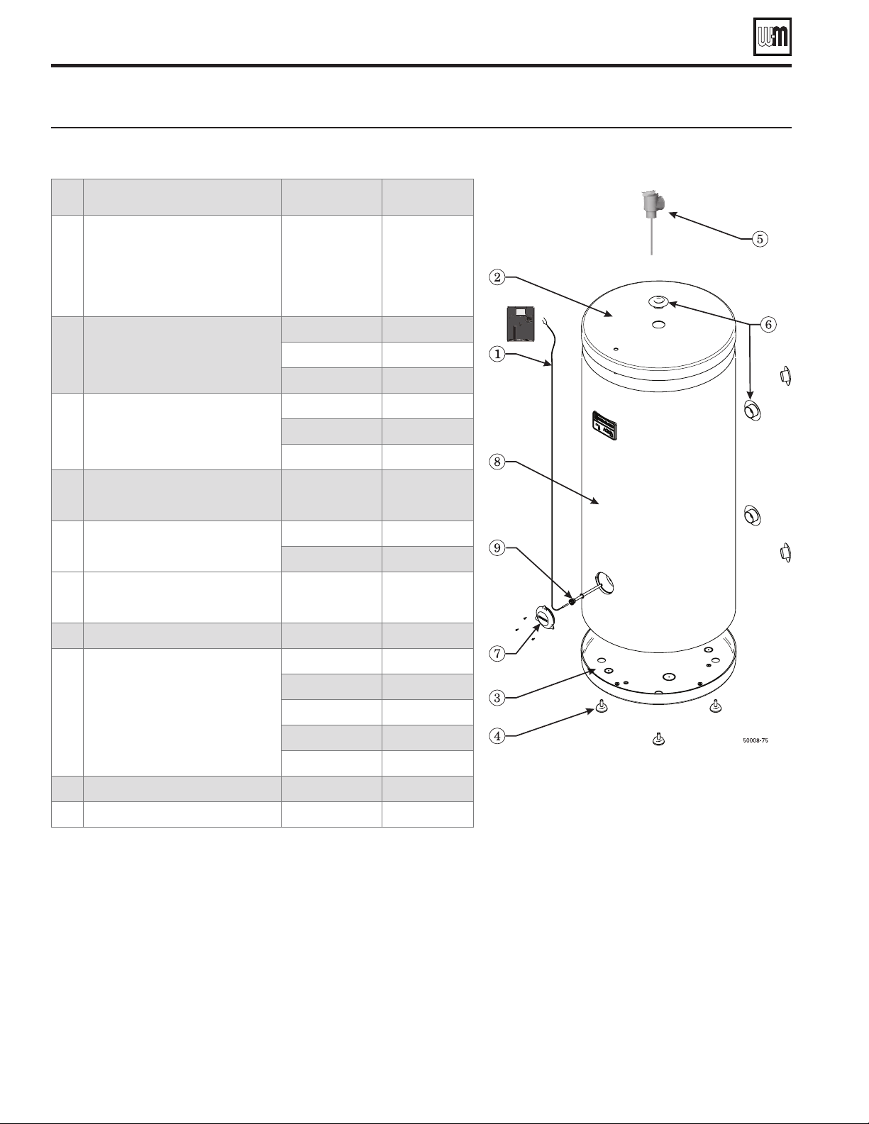
AQUA PLUS® Series 2 indirect-fired water heaters — Product Manual
Replacement parts
Figure 30 Indirect Water Heater replacement parts
Item Description
Thermostat repair kit
1
(Control and sensor included)
2 T op plastic cap replacement kit
Bottom plastic cap replacement kit
3
(plastic cap and 4 screws)
4 Leveling leg replacement kit (4) All 633-500-036
emperature & pressure relief
T
5
valve kit
6 Fitting grommet
Size/Model
AQUA PLUS
AQUA PLUS®
Residential
35/45/55/
85/105
35/45/55 633-500-024
85 633-500-025
105 633-500-026
35/45/55 633-500-030
85 633-500-031
105 633-500-032
35/45/55 633-500-038
85/105 633-500-039
¾”
1”
Part Number
®
633-600-012
633-500-064
633-500-037
7 Sensor cover All 633-500-131
35, Pewter 633-500-132
45, Pewter 633-500-133
8 Jacket replacement kit
9 Thermowell All 633-500-137
– Mixing valve kit, 1" (not shown) All 633-500-012
55, Pewter 633-500-134
85, Pewter 633-500-135
105, Pewter 633-500-136
38
Part number 633-600-020/0118
Page 39
AQUA PLUS® Series 2 indirect-fired water heaters — Product Manual
Rating - AQUA PLUS® Series 2
Figure 31 Indirect Water Heater Ratings
®
AHRI Certified Data
180°F boiler water entering | 58°F to 135°F domestic water
Model
AQUA
PLUS
Series 2
35
45
55
85
105
Potable
Water
Volume
(Gal) (Gal) (Gal/hr)
Heat Source
Water Volume
First Draw
Rating
Standby
Heat Loss
Degrees F
per hour
Continuous
Draw Rating
(Gal/hr) (Gal/hr) (MBH) GPM Feet w.c.
First Hour
Rating
Minimum Heat
Output Rate
Minimum
Heat Source
Flow Rate
Heat Source
Friction Loss
29.7 1.7 21 1.0 202 223 127 14 3.8
39.9 1.9 35 0.8 221 256 140 14 3.4
54.1 2.2 50 0.6 248 298 156 14 3.5
81.6 2.7 67 0.5 280 347 178 14 3.5
110.9 3.9 72 0.4 376 448 235 14 4.9
These ratings were obtained with a heat source output rate of 234,000 Btu/h at a heat source flow rate of 14 gpm.
Part number 633-600-020/0118
Other results shall be obtained under different conditions.
39
Page 40
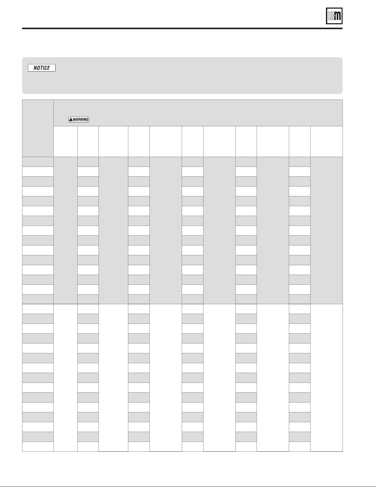
AQUA PLUS® Series 2 indirect-fired water heaters — Product Manual
Ratings with 200°F boiler supply water
For water heater to achieve the rated performance below: Boiler water must be supplied to the water heater at 200°F,
and the boiler water flow rate must be no less than given in the tables below. (For AquaBalance, ECO, Evergreen,
GV90+, Ultra Gas boiler, Ultra Oil boiler or WM97+ boiler applications, with supply water at 190°F, see the ratings in the boiler manual.)
Boiler
Heating
Capacity
MBH
50
70
90
110
130
150
170
190
210
250
300
350
400
450
500
50
70
90
110
130
150
170
190
210
250
300
350
400
450
500
First Hour Rating Capacity (GPH) — Boiler Water Supply at 200°F
DO NOT exceed the boiler-side flow rate listed in “Maximum boiler-side flow rate,” page 26
DHW
temps
AQUA
PLUS
35
93
120 130 151 165 175
147 157 178 192 202
174 184 205 219 229
201 211 232 246 256
223 237 259 273 283
223 243 286 300 310
223 243 302 327 337
223 243 302 354 363
223 243 302 374 417
223 243 302 374 483
DHW 50°F to 140°F
223 243 302 374 483
223 243 302 374 483
223 243 302 374 483
223 243 302 374 483
119
157 166 188 201 211
194 203 225 239 249
231 241 262 276 286
268 278 299 313 323
306 315 337 351 360
337 352 374 388 398
337 363 411 425 435
337 363 443 462 472
337 363 443 537 547
337 363 443 551 640
DHW 50°F to 115°F
337 363 443 551 715
337 363 443 551 715
337 363 443 551 715
337 363 443 551 715
Boiler
Water
Min GPM &
Head Loss
8 GPM
minimum
@
1.6 ft w.c.
8 GPM
minimum
@
1.6 ft w.c.
AQUA
PLUS
45
103
Boiler
Water
Min GPM &
Head Loss
AQUA
PLUS
55
124
8 GPM
minimum
@
1.6 ft w.c.
129
150
8 GPM
minimum
@
1.6 ft w.c.
Boiler
Water
Min GPM &
Head Loss
8 GPM
minimum
@
1.6 ft w.c.
8 GPM
minimum
@
1.6 ft w.c.
AQUA
PLUS
85
138
164
Boiler
Water
Min GPM &
Head Loss
14 GPM
minimum
@
5.4 ft w.c.
14 GPM
minimum
@
5.4 ft w.c.
AQUA
PLUS
105
148
174
Boiler
Water
Min GPM &
Head Loss
14 GPM
minimum
@
7.1 ft w.c.
14 GPM
minimum
@
7.1 ft w.c.
40
Part number 633-600-020/0118
Page 41
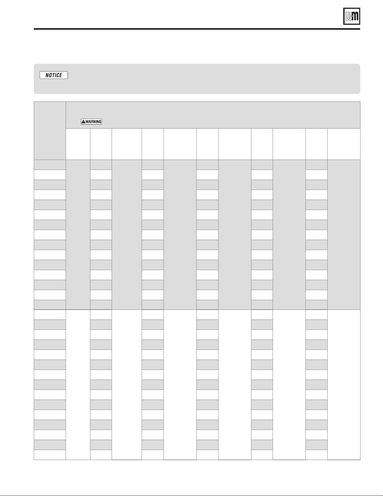
AQUA PLUS® Series 2 indirect-fired water heaters — Product Manual
Ratings with 190°F boiler supply water
For water heater to achieve the rated performance below: Boiler water must be supplied to the water heater at least
190°F, and the boiler water flow rate must be no less than given in the tables below.
Boiler
Heating
Capacity
MBH
50
70
90
110
130
150
170
190
210
250
300
350
400
450
500
50
70
90
110
130
150
170
190
210
250
300
350
400
450
500
First Hour Rating Capacity (GPH) — Boiler Water Supply at 190°F
DO NOT exceed the boiler-side flow rate listed in “Maximum boiler-side flow rate,” page 26
DHW
temps
AQUA
PLUS
35
93
120 130 151 165 175
147 157 178 192 202
174 184 205 219 229
201 211 232 246 256
202 222 259 273 283
202 222 278 300 310
202 222 278 327 337
202 222 278 343 363
202 222 278 343 417
202 222 278 343 442
DHW 50°F to 140°F
202 222 278 343 442
202 222 278 343 442
202 222 278 343 442
202 222 278 343 442
119
157 166 188 201 211
194 203 225 239 249
231 241 262 276 286
268 278 299 313 323
306 315 337 351 360
311 335 374 388 398
311 335 411 425 435
311 335 411 462 472
311 335 411 511 547
311 335 411 511 640
DHW 50°F to 115°F
311 335 411 511 662
311 335 411 511 662
311 335 411 511 662
311 335 411 511 662
Boiler
Water
Min GPM &
Head Loss
8 GPM
minimum
1.6 ft w.c.
8 GPM
minimum
1.6 ft w.c.
@
@
AQUA
PLUS
45
103
Boiler
Water
Min GPM &
Head Loss
AQUA
PLUS
55
124
8 GPM
minimum
@
1.6 ft w.c.
129
150
8 GPM
minimum
@
1.6 ft w.c.
Boiler
Water
Min GPM &
Head Loss
8 GPM
minimum
@
1.6 ft w.c.
8 GPM
minimum
@
1.6 ft w.c.
AQUA
PLUS
85
138
164
Boiler
Water
Min GPM &
Head Loss
14 GPM
minimum
@
5.4 ft w.c.
14 GPM
minimum
@
5.4 ft w.c.
AQUA
PLUS
105
148
174
Boiler
Water
Min GPM &
Head Loss
14 GPM
minimum
@
7.1 ft w.c.
14 GPM
minimum
@
7.1 ft w.c.
Part number 633-600-020/0118
41
Page 42
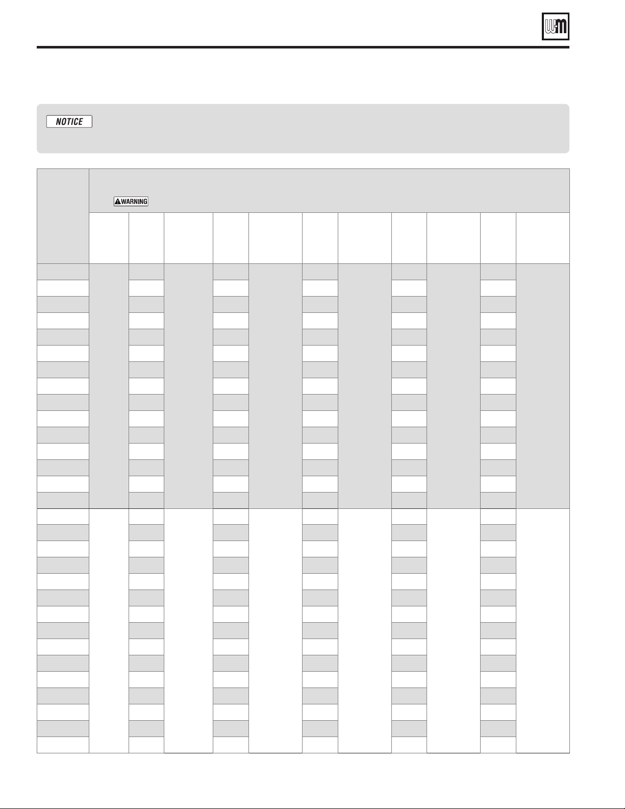
AQUA PLUS® Series 2 indirect-fired water heaters — Product Manual
Ratings with 180°F boiler supply water
For water heater to achieve the rated performance below: Boiler water must be supplied to the water heater at least
180°F, and the boiler water flow rate must be no less than given in the tables below.
Boiler
Heating
Capacity
MBH
50
70
90
110
130
150
170
190
210
250
300
350
400
450
500
50
70
90
110
130
150
170
190
210
250
300
350
400
450
500
First Hour Rating Capacity (GPH) — Boiler Water Supply at 180°F
DO NOT exceed the boiler-side flow rate listed in “Maximum boiler-side flow rate,” page 26
DHW
temps
AQUA
PLUS
35
93
120 130 151 165 175
147 157 178 192 202
174 184 205 219 229
181 200 232 246 256
181 200 252 273 283
181 200 252 300 310
181 200 252 310 337
181 200 252 310 363
181 200 252 310 400
181 200 252 310 400
DHW 50°F to 140°F
181 200 252 310 400
181 200 252 310 400
181 200 252 310 400
181 200 252 310 400
119
156 166 187 201 211
193 203 224 238 248
231 240 262 275 285
268 277 299 313 322
284 307 336 350 360
284 307 373 387 397
284 307 378 424 434
284 307 378 461 471
284 307 378 470 545
284 307 378 470 608
DHW 50°F to 115°F
284 307 378 470 608
284 307 378 470 608
284 307 378 470 608
284 307 378 470 608
Boiler
Water
Min GPM &
Head Loss
8 GPM
minimum
@
1.6 ft w.c.
8 GPM
minimum
@
1.6 ft w.c.
AQUA
PLUS
45
103
Boiler
Water
Min GPM &
Head Loss
AQUA
PLUS
55
124
8 GPM
minimum
@
1.6 ft w.c.
129
150
8 GPM
minimum
@
1.6 ft w.c.
Boiler
Water
Min GPM &
Head Loss
8 GPM
minimum
@
1.6 ft w.c.
8 GPM
minimum
@
1.6 ft w.c.
AQUA
PLUS
85
138
164
Boiler
Water
Min GPM &
Head Loss
14 GPM
minimum
@
5.4 ft w.c.
14 GPM
minimum
@
5.4 ft w.c.
AQUA
PLUS
105
148
174
Boiler
Water
Min GPM &
Head Loss
14 GPM
minimum
@
7.1 ft w.c.
14 GPM
minimum
@
7.1 ft w.c.
42
Part number 633-600-020/0118
Page 43
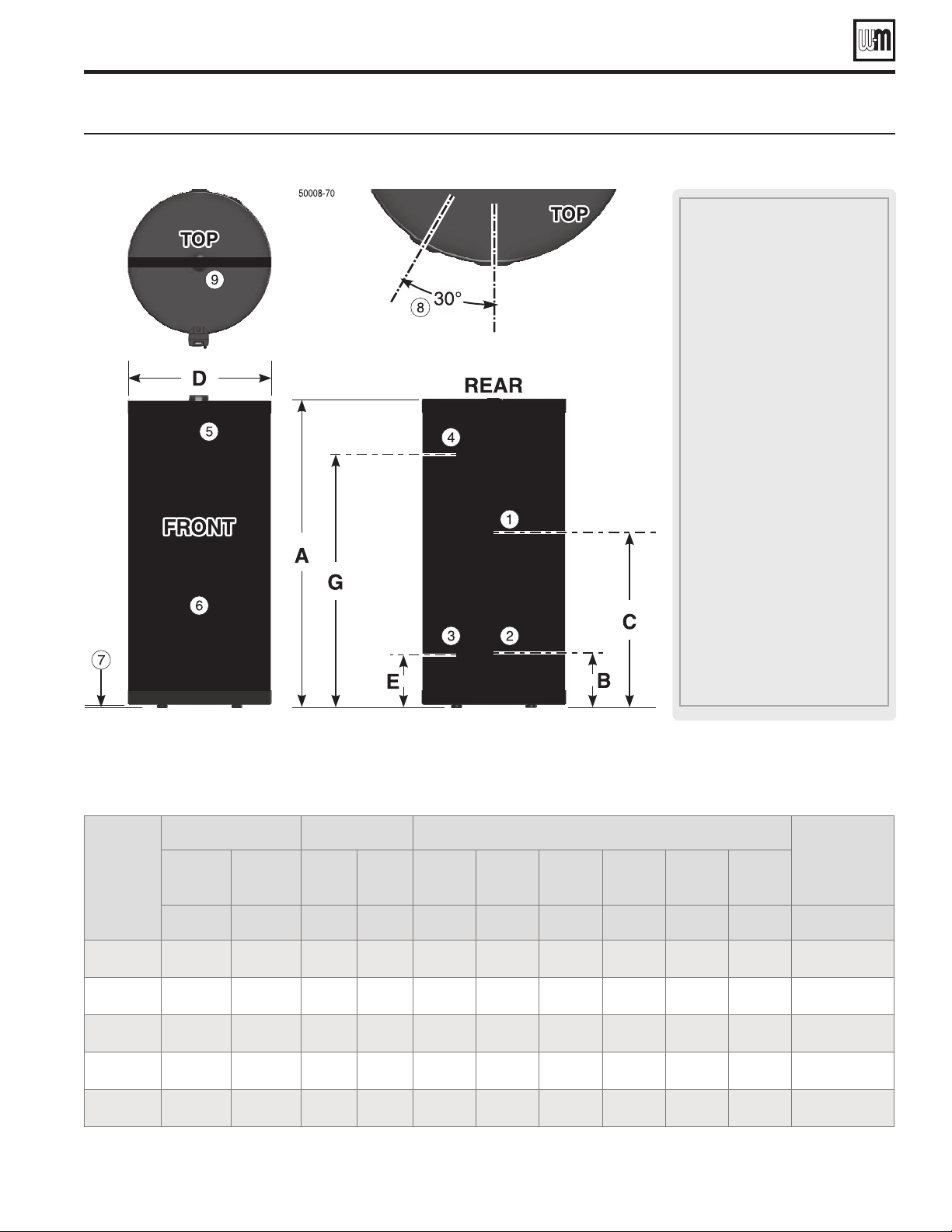
AQUA PLUS® Series 2 indirect-fired water heaters — Product Manual
Dimensions
Figure 32 Dimensions and ratings — AQUA PLUS
®
Series 2 Indirect-fired Water Heaters
1 Boiler water inlet (see table
for size)
2 Boiler water outlet (see table
for size)
3 Cold domestic water inlet
(see table for size)
4 Hot domestic water outlet
(see table for size)
5 Electronic digital thermostat
with adjustment knob
6 Sensor cover
7 Adjustable leg adjustment
range = 5/8” to 1¼” (add
this amount to the height
dimensions for total height
from floor)
8 Angle between boiler water
connections and domestic
water connections
Model
AQUA
PLUS
Series 2
35
45
55
85
DHW
®
side
Gallons Gallons
29.7 1.7
39.9 1.9
54.1 2.2
81.6 2.7
Storage Connections Dimensions (inches)
Boiler
side
DHW
In/Out
Inches
NPT
Boiler
water
In/Out
Inches
NPT
C\v 1 36C\, 7M\, 24 21M\, 7C\, 28
C\v 1 46Z\v 7M\, 26 21M\, 7C\, 37M\,
C\v 1 60 7M\, 29M\, 21M\, 7C\, 51B\,
1 1 59Z\x 10C\, 33Z\v 26 8M\, 50C\,
A B C D E
Inches Inches Inches Inches Inches Inches Pounds
9 Connection for T&P valve
(¾”) — valve supplied loose
with the water heater; field
installed
Shipping
weight
G
(approx.)
94
111
122
223
105
Part number 633-600-020/0118
110.4 3.9
1 1 59C\v 14Z\v 41C\, 30 9M\, 48B\,
238
43
Page 44

AQUA PLUS® Series 2 indirect-fired water heaters — Product Manual
44
Part number 633-600-020/0118
 Loading...