

Page 1
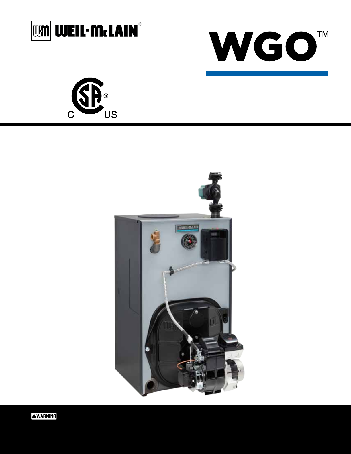
Series 4
Oil-Fired Water Boilers
Boiler Manual
• Installation
• Startup
• Maintenance
• Parts
This manual must only be used by a qualied heating installer/service technician. BEFORE installing, read
all instructions in this manual and all other information shipped with the boiler. Perform steps in the order
given. Failure to comply could result in severe personal injury, death or substantial property damage.
Part number 550-142-331/0421
Page 2
WGO
OIL-FIRED NATURAL DRAFT WATER BOILER — SERIES 4 — Boiler Manual
HOMEOWNER and SERVICE TECHNICIAN — read and follow completely.
Using this manual
Homeowner —
Read and follow all information on pages 1 through 7 ONLY.
Service technician —
Read and follow ALL information in the entire manual.
Failure to follow all instructions in proper order can cause severe personal injury, death or
substantial property damage.
When calling or writing about the boiler
Please have boiler model number and series from boiler rating label and Consumer Protection (CP)
number(s) from boiler jacket, burner and controls. On page 28 of this manual is space to list CP number(s).
Packaged, Semi-packaged, and knocked-down boilers
Packaged boilers: Available only in sizes 2 through 6, are factory assembled, completed with block, collector
hood, jacket, controls and trim. Burner is ordered and shipped separately.
Semi-packaged boilers Available only in sizes 2 through 6, are shipped with block assembled with collector hood
and jacket installed. Control, trim, and burner are ordered and shipped separately for field
assembly.
Knocked-down boilers Available in sizes 2 through 9, are shipped with block assembled only. All other components
are ordered and shipped separately for field assembly.
Hazard definitions
The following defined terms are used throughout this manual to bring attention to the presence of hazards
of various risk levels or to important information concerning the life of the product.
Indicates presence of hazards that will cause severe personal injury,
death or substantial property damage.
Indicates presence of hazards that can cause severe personal injury,
death or substantial property damage.
Indicates presence of hazards that will or can cause minor personal
injury or property damage.
Indicates special instructions on installation, operation or
maintenance that are important but not related to personal injury
or property damage.
2
Part number 550-142-331/0421
Page 3

WGO
OIL-FIRED NATURAL DRAFT WATER BOILER — SERIES 4 — Boiler Manual
Contents
HOMEOWNER and SERVICE TECHNICIAN — read and follow completely.
Using this manual . . . . . . . . . . . . . . . . 2
Homeowner. . . . . . . . . . . . . . . . . . 2
Service techicians . . . . . . . . . . . . . . . . . . .2
When calling or writing about the boiler . . . . . . . .2
Packaged, Semi-packaged and Knocked-down boilers 2
Hazard definitions . . . . . . . . . . . . . . . . 2
Contents . . . . . . . . . . . . . . . . . . . . 3
Please read before proceeding . . . . . . . . . 4
Homeowner. . . . . . . . . . . . . . . . . . 4
Service techicians . . . . . . . . . . . . . . . . . . .4
Tips for water systems — . . . . . . . . . . . . . . .4
Saltwater Damage . . . . . . . . . . . . . . . . . . .4
Electrical Damage . . . . . . . . . . . . . . . . . . .4
Frozen Water Damage Hazard . . . . . . . . . . . . .5
Routine maintenance schedule . . . . . . . . . 5
Beginning each heating season . . . . . . . . . . . .5
Daily during heating season . . . . . . . . . . . . . .5
Weekly during heating season . . . . . . . . . . . . .5
End of heating season . . . . . . . . . . . . . . . . .5
Boiler shutdown . . . . . . . . . . . . . . . . . . . .5
Operation . . . . . . . . . . . . . . . . . . . . 6
WGO (see Figure 1) . . . . . . . . . . . . . . . . . . .6
Troubleshooting . . . . . . . . . . . . . . . . . 7
Before installing boiler . . . . . . . . . . . . . 8
Installations must comply with . . . . . . . . . . . . .8
Before selecting boiler location . . . . . . . . . . . .8
Provide clearances around boiler
(see Figure 2) . . . . . . . . . . . . . . . . . . . . . .8
Provide air for combustion and ventilation . . . . . .9
Foundation . . . . . . . . . . . . . . . . . . . . . . .9
Install boiler — Packaged boilers only. . . . . .10
Place boiler . . . . . . . . . . . . . . . . . . . . . .10
Perform hydrostatic pressure test . . . . . . . . . .10
Install boiler - Semi-packaged & Knocked-down boilers12
Place boiler . . . . . . . . . . . . . . . . . . . . . .12
Perform hydrostatic pressure test . . . . . . . . . .14
Install jacket
(Knocked-down boiler only) . . . . . . . . . . . . . 14
Install boiler controls . . . . . . . . . . . . . . . . .14
Install burner — all boilers . . . . . . . . . . .15
Install burner
(also refer to instructions packed with burner) . . . 15
Connect breeching . . . . . . . . . . . . . . .16
General chimney requirements. . . . . . . . . . . . 16
Connect water piping . . . . . . . . . . . . . .18
General piping information . . . . . . . . . . . . . . 18
Install piping . . . . . . . . . . . . . . . . . . . . . 18
DIAPHRAGM expansion tank (Figure 11) . . . . . . 19
CLOSED expansion tank (Figure 12) . . . . . . . . . 19
To connect WGO boilers to indirect-fired
water heaters . . . . . . . . . . . . . . . . . . . . .18
Piping MULTIPLE ZONES . . . . . . . . . . . . . . 20
Piping for systems requiring
temperatures below 140°F . . . . . . . . . . . . . .21
Use with refrigeration systems . . . . . . . . . . . . 22
Connect wiring . . . . . . . . . . . . . . . . .22
General wiring requirements . . . . . . . . . . . . .22
Thermostat wiring . . . . . . . . . . . . . . . . . . 22
3-Wire zone valve applications. . . . . . . . . . . . 22
General wiring . . . . . . . . . . . . . . . . . . . . 23
Burner wiring . . . . . . . . . . . . . . . . . . . . .23
High temperature limit . . . . . . . . . . . . . . . . 23
Connect wiring — blocked vent
shutoff switch option . . . . . . . . . . . . . .25
Blocked vent shutoff switch . . . . . . . . . . . . . 25
Connect wiring - vent damper . . . . . . . . . . 26
Connect oil piping . . . . . . . . . . . . . . . . 26
General oil piping requirements . . . . . . . . . . .26
Oil piping connection at burner . . . . . . . . . . . 26
Start-up . . . . . . . . . . . . . . . . . . . . .27
Fill the system . . . . . . . . . . . . . . . . . . . . 27
When using antifreeze . . . . . . . . . . . . . . . . 27
To place in operation . . . . . . . . . . . . . . . . .27
Check-out procedure . . . . . . . . . . . . . .28
Check off steps as completed . . . . . . . . . . . .28
Installation and service certificate . . . . . . . . . .28
Annual service check list . . . . . . . . . . . .29
Controls requiring annual service . . . . . . . . . . 29
Detailed service procedures. . . . . . . . . . .30
Cleaning boiler flue ways. . . . . . . . . . . . . . . 30
General description of control operation . . . . . . 30
Close clearance installation . . . . . . . . . . . 31
Close clearance installation . . . . . . . . . . . . . 31
Burner adjustments . . . . . . . . . . . . . . . . .31
Replacement parts . . . . . . . . . . . . . . . 33
Dimensions . . . . . . . . . . . . . . . . . . .38
Ratings . . . . . . . . . . . . . . . . . . . . . 39
Handling ceramic fiber and fiberglass materials 40
Part number 550-142-331/0421
3
Page 4
WGO
OIL-FIRED NATURAL DRAFT WATER BOILER — SERIES 4 — Boiler Manual
HOMEOWNER and SERVICE TECHNICIAN — read and follow completely.
Please read before proceeding
Homeowner —
• For homeowner or person responsible for
simple start-up and routine maintenance of
the system
• Instructions on pages 1 through page 7 must
be followed to assure proper operation of
your boiler. See page 7 for a list of common
problems and possible corrections. In addition, it is your responsibility to:
• Have boiler and burner installed by a
qualified installer.
• Have boiler and burner serviced annually
by a qualified service technician.
• Review and understand start-up and
routine maintenance procedures with
qualified service technician.
• Perform routine maintenance as de-
scribed on page 5.
Service technician —
• For a qualified service technician who has
the necessary equipment to check the boiler
and system performance, and is responsible
for start-up and service of boiler and system.
• All instructions in this manual must be
followed to assure proper operation of this
boiler.
• Annually service boiler and burner to assure
proper operation. See page 29 for service
record.
• Review and explain start-up and routine
maintenance procedures with homeowner.
Follow instructions below to pre-
vent severe personal injury, death
or substantial property damage:
• Do not use crankcase drainings or any oil
containing gasoline. See burner manual for
proper fuel oil.
• Do not attempt to start burner when excess
oil has accumulated in combustion chamber, when unit is full of vapor, or when
combustion chamber is very hot.
• Do not start burner unless collector hood,
flue cap, jacket cap, breeching and burner
mounting door are secured in place.
• Never burn garbage or paper in the boiler.
Never leave combustible material around
boiler.
• DO NOT TAMPER WITH UNIT OR CONTROLS. Always follow specific instructions
when starting up boiler or performing routine maintenance or service.
Follow instructions below to prevent severe personal injury,
death or substantial property damage:
• To avoid electric shock, disconnect electrical supply to burner service
switch and additional external switches before performing service.
• To avoid severe burns, allow boiler to cool before performing service.
• Do not block flow of combustion or ventilation air to boiler.
• Boiler must be connected to a flue with sufficient draft at all times to
assure proper operation.
• Do not use this boiler if any part has been under water. Electrical and
mechanical failures may cause electric shock and fire risks. Immediately
call a qualified service technician to inspect chimney or vent, boiler
and burner. Have the boiler flue ways cleaned and have the following
replaced:
• all electrical and mechanical controls
• electrical wiring
• oil burner and controls
• insulation and chamber lining
Tips for water systems —
• Check boiler and system piping for leaks. Continual makeup water
will reduce boiler life. Minerals can build up in sections, reducing heat
transfer and causing cast iron to overheat, resulting in section failure.
Failure to maintain recommended pH and repair leaks can
cause section iron corrosion, leading to section failure and
leaks. Do not use petroleum-based sealing or stop-leak compounds in boiler systems. Damage to system components
can result, causing property damage.
• Boiler water pH 7.0 to 8.5 is recommended. For pH conditions outside
7.0 to 8.5 range or unusually hard water areas (above 7 grains hardness), consult local water treatment company.
• When using antifreeze:
Use antifreeze especially made for hydronic systems. Inhibited
propylene glycol is recommended.
Do not use automotive, ethylene glycol, undiluted or
petroleum-based antifreeze. Severe personal injury, death
or substantial property damage can result.
50% solution provides protection to about –30°F.
Local codes may require back-flow preventer or actual disconnect
from city water supply.
Determine quantity according to system water content. Boiler water
content is listed on back cover of the manual.
Percent of solution will affect sizing of heat distribution units,
circulator and expansion tank.
Follow antifreeze manufacturer’s instructions.
Do not add cold water to hot boiler. Thermal shock can cause
sections to crack.
Saltwater Damage — The exposure of boiler components to saltwater
can have both immediate and long-term effects. While the immediate
effects of saltwater damage are similar to those of freshwater (shorting
out of electrical components, washing out of critical lubricants, etc.), the
salt and other contaminants left behind can lead to longer term issues
after the water is gone due to the conductive and corrosive nature of
the salt residue. Therefore, Weil-McLain equipment contaminated with
saltwater or polluted water will no longer be covered under warranty
and should be replaced.
Electrical Damage — If any electrical component or wiring came
into contact with water, or was suspected to have come into contact with
water, replace the boiler with a new Weil-McLain boiler.
continued - top of next page
4
Part number 550-142-331/0421
Page 5
WGO
Residences or buildings that are unattended in severely cold weather, boiler system components failures, power outages, or
other electrical system failures could result in frozen plumbing and water damage in a matter of hours. For your protection, take
preventative actions such as having a security system installed that operates during power outages, senses low temperature, and
initiates an effective action. Consult with your boiler contractor or a home security agency.
OIL-FIRED NATURAL DRAFT WATER BOILER — SERIES 4 — Boiler Manual
HOMEOWNER and SERVICE TECHNICIAN — read and follow completely.
Frozen Water Damage Hazard
Routine maintenance schedule
Beginning
each heating season
Daily
during heating season
Weekly
during heating season
End
of heating season
Call a qualified service technician to perform annual service.
Check that boiler area is free from combustible materials, gasoline
and other flammable vapors and liquids.
Check for and remove any obstructions to flow of combustion or
ventilation air to boiler.
Check that breeching is attached between boiler and chimney. If
breeching is loose or damaged, immediately turn off switch on
boiler and call service technician to repair.
Check for oil leaks in oil piping and around burner. If found, im-
mediately call qualified service technician to correct situation.
Check for water leaks in boiler and piping; also check for leaks
around tankless heater plate, if installed. If found, immediately call
service technician to repair.
If tankless heater is installed, boiler will continue to operate. Check
for the following:
• All daily and weekly instructions listed on this page must be followed.
• Burner motor may have to be oiled. Some motors are permanently
lubricated and do not need additional oil. Check for oiling instructions on burner or motor.
Boiler
shutdown
Part number 550-142-331/0421
Do not drain boiler unless exposure to freezing temperatures will
occur.
Always keep manual fuel supply shut off if burner is shut down for
an extended period of time.
• Turn off switch at boiler and any external switch to boiler.
• Close fuel valves.
• Turn off water feed valve.
• Cover burner to protect from dust and dampness.
5
Page 6
WGO
OIL-FIRED NATURAL DRAFT WATER BOILER — SERIES 4 — Boiler Manual
Operation
HOMEOWNER and SERVICE TECHNICIAN — read and follow completely.
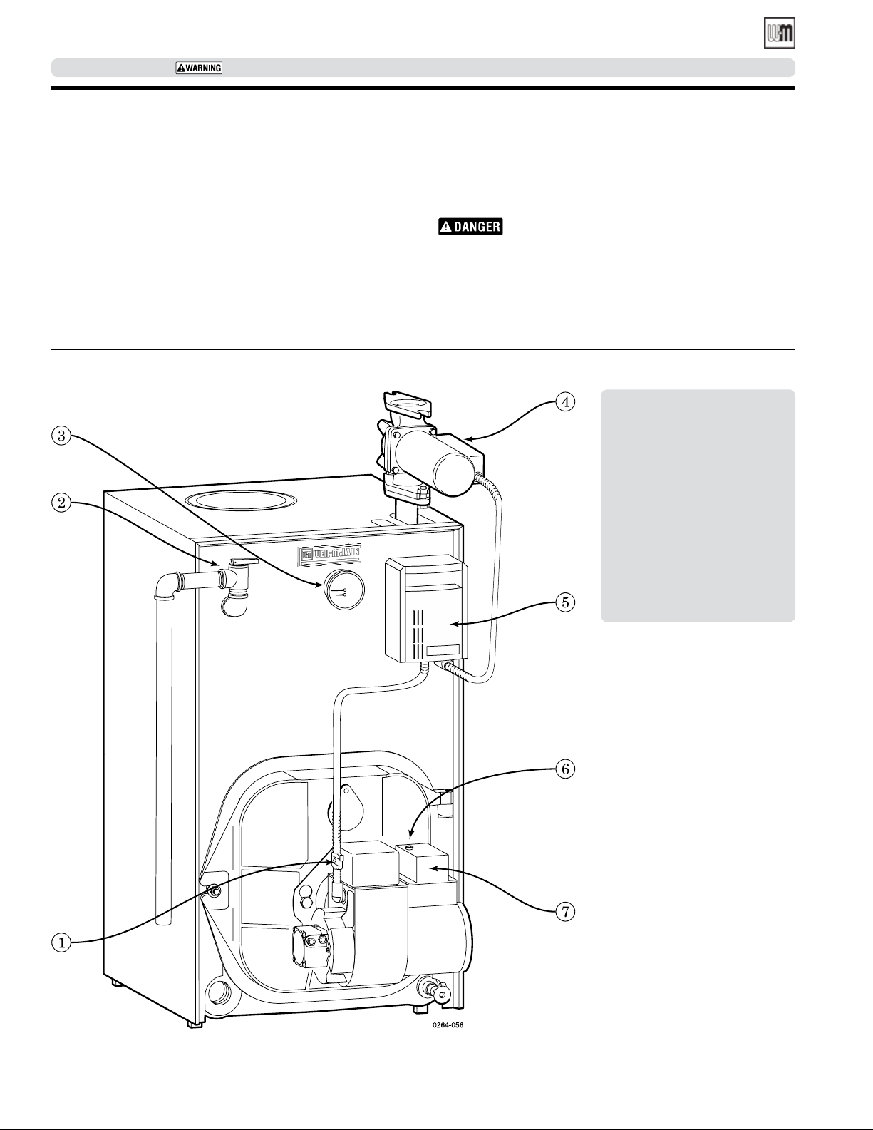
WGO (see Figure 1)
1. If burner does not fire, check for:
• Service switch on control or additional switches turned
off.
• Fuses or breaker switch tripped.
• Thermostat set below room temperature.
• Fuel valves turned off.
• Not enough oil in tank to supply burner.
Figure 1 WGO Boilers
2. Correct problems found in step #1. If burner does not fire,
press reset button on burner primary control only once.
Repeated presses will deposit oil in combustion chamber.
Burner must never be fired when oil is in combus-
tion chamber. Immediately call qualified service
technician.
3. If burner still does not fire, call qualified service technician.
1 Burner disconnect plug
2 Water relief valve
3 Temperature-pressure gauge
4 Circulator
5 Limit control / low water
cut-off
6 Reset button on burner
primary control
7 Burner primary control
6
Part number 550-142-331/0421
Page 7
WGO
OIL-FIRED NATURAL DRAFT WATER BOILER — SERIES 4 — Boiler Manual
HOMEOWNER and SERVICE TECHNICIAN — read and follow completely.
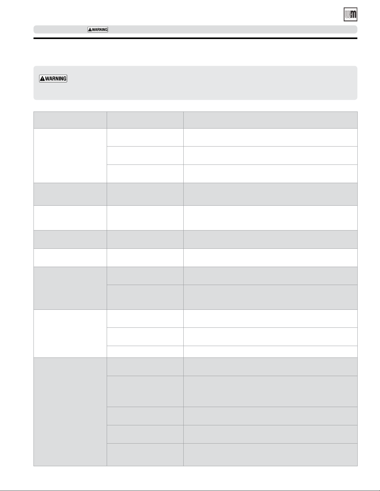
Troubleshooting
Homeowners — The problems and corrections below represent common situations that can occur. There may be
others not listed below. It is important always to contact a qualified service technician if you have any questions
about the operation of your boiler or system.
Common Problems Common Causes Possible Corrections
Rapid cycling — burner
turns on and off
frequently.
Need to frequently add
makeup water.
Popping or percolating
noise heard in boiler.
Black water condition.
Frequent release of water
through relief valve.
Metal flakes found in flue
way.
Thermostat installed where
Locate thermostat on inner wall away from heat sources or cool drafts.
drafts or heat affect reading.
Heat anticipator in thermostat adjusted incorrectly.
Adjust heat anticipator to match current draw. Refer to boiler wiring
diagram.
Incorrect limit setting. Have qualified service technician increase limit setting to decrease
cycling. Maximum setting 220° F.
Leaks in boiler or piping. Have qualified service technician repair leaks at once to avoid constant
use of makeup water.
Mineral deposits in sections
due to constant use of makeup water, or incorrect pH.
Oxygen corrosion due to
leaks in piping. Improper pH.
Expansion tank sized too
Have qualified service technician de-lime boiler, repair leaks at once
to avoid constant use of makeup water and check pH (between 7.0
and 8.5).
Have qualified service technician repair leaks at once to avoid constant
use of makeup water and check pH (between 7.0 and 8.5).
Have qualified service technician check expansion tank operation.
small or water-logged.
Contaminated combustion
air supply in flue ways.
Condensation of combustion
gases.
Remove sources of hydrocarbons in or near boiler area. (Bleaches,
cleaners, chemicals, sprays, fabric softeners, paint remover, etc.)
Have qualified service technician check burner nozzle and oil pump
pressure for proper firing rate and check/adjust combustion settings
with an analyzer.
Some radiators or
baseboard units do not
heat or are noisy.
Domestic water from
tankless heater is hot
then suddenly turns cold.
OR
Domestic water from
tankless heater is always
lukewarm.
Part number 550-142-331/0421
Air in system. Bleed air from system through air vents in radiators or baseboard units.
Low system pressure. Have qualified service technician check for leaks in boiler or piping
at once.
High limit set too low. Have qualified service technician adjust limit to higher setting.
Mineral deposits insulate
Have qualified service technician delime or replace coil.
internal waterways of heater.
Boiler stop-leak compound
has been added to boiler wa-
Have qualified service technician remove and clean coil and drain,
and flush boiler to remove stop-leak.
ter and is insulating outside
of coil.
Incorrect mixing valve setting
Have qualified service technician adjust mixing valve setting.
for tankless heater.
Domestic flow rate too high. Have qualified service technician install flow check valve set to rating
of tankless heater.
Incorrect setting on tankless
heater control.
Have qualified service technician raise tankless control setting. Adjust
differential on tankless control to lower setting.
7
Page 8
WGO
OIL-FIRED NATURAL DRAFT WATER BOILER — SERIES 4— Boiler Manual
SERVICE TECHNICIAN ONLY — read and follow completely.
Before installing boiler
Homeowner — STOP! The procedures and information on this and following pages are intended only for a
qualified service technician who has the necessary equipment to inspect and adjust boiler and burner. A homeowner
should never attempt these procedures. The service technician must also read pages 1 through 7 before proceeding.
Installations must comply with
United States
• State and local plumbing, heating and electrical codes.
• National codes where applicable.
• Standard for Controls and Safety Devices for Automatically Fired
Boilers, ANSI/ASME CSD-1, – latest edition, when required.
• National Electrical Code, ANSI/NFPA 70, – latest edition
and any additional national, state or local codes.
Canada
• Canadian Standards Association, CSA B139, Installation Code for OilBurning Equipment - latest edition.
• CSA C22.1 Canadian Electrical Code Part One - latest edition.
• Applicable local or provincial codes.
Before selecting boiler location
Check for nearby connections to:
• System water piping.
• Chimney. See page 16. Boiler can be top or back vented.
• Combustion and ventilation air supply. See page 9.
• Oil supply. See page 26 for oil line routing.
• Electrical power.
• Check area around boiler. Remove any combustible materials, gasoline and other flammable liquids.
Failure to keep boiler area clear and free of combustible materials, gasoline and other flammable liquids and vapors
can result in severe personal injury, death or substantial property damage.
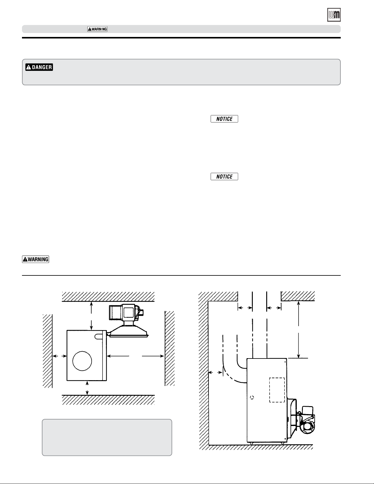
Provide clearances around boiler
(see Figure 2)
Jacket cap must be in place on boiler to
avoid requiring an 9" minimum clearance
from back or top of boiler to combustible
material.
MINIMUM clearances from vent pipe to
combustible material
• 6 inches — Type “L” double-wall vent*
• 9 inches — Single-wall vent*
Flue pipe clearances must take precedence
over jacket clearances.
Recommended SERVICE clearances
• 24 inches — Front and top
• 6 inches — Left side, back and right side
• 12 inches — Right side for burner door
swing radius
• Special close clearances (alcove, closet, under
counters, etc.) — see Close Clearance Installation,
page 31.
Figure 2 Recommended service clearances
A
A
A
Top View
A Provide 6" minimum clearance for service, provide 12"
minimum clearance for burner door swing.
B Minimum clearance from vent pipe to combustible mate-
rial: 6" for type “L” double-wall vent, 9" for single-wall
vent.
24"
Walls
B
Wall
B
Left side
Ceiling
B
24"
Floor
8
Part number 550-142-331/0421
Page 9
WGO
OIL-FIRED NATURAL DRAFT WATER BOILER — SERIES 4 — Boiler Manual
SERVICE TECHNICIAN ONLY — read and follow completely.
Before installing boiler (continued)
Provide air for combustion and ventilation
Do not install exhaust fan in boiler room.
Adequate combustion and ventilation air:
• Assures proper combustion.
• Reduces risk of severe personal injury or death from possible flue
gas leakage and carbon monoxide emissions.
Older buildings with single-pane windows, minimal weather-stripping
and no vapor barrier often provide enough natural infiltration and
ventilation without dedicated openings.
New construction or remodeled buildings are most often built tighter.
Windows and doors are weather-stripped, vapor barriers are used and
openings in walls are caulked. As a result, such tight construction is
unlikely to allow proper natural air infiltration and ventilation.
Follow state, provincial or local codes when sizing adequate combustion
and ventilation air openings. In absence of codes, use the following
guidelines when boiler is in a confined room (defined by NFPA 31 as
less than 7200 cubic feet per 1 GPH input of all appliances in area. A
room 8 ft. high x 33.5 ft. x 33.5 ft. is 7200 cu. ft.).
Permanent Openings
Provide two permanent openings, one within 12 inches of ceiling, one
within 12 inches of floor. Minimum height or length dimension of
each rectangular opening should be at least 3 inches.
Where ducts are used, they should have same cross-sectional area as free area of openings to which they connect.
Compensate for louver, grille or screen blockage when
calculating free air openings. Refer to their manufacturer’s
instructions for details. If unknown, use:
• Wood louvers, which provide 20-25% free air.
• Metal louvers or grilles, which provide 60-75% free air.
Lock louvers in open position or interlock with equipment
to prove open before boiler operation.
Foundation
Lay a foundation, if needed. Boiler may be installed on
non-carpeted combustible flooring. Solid concrete blocks
can be used to create a pad.
For residential garage installation, install boiler so burner
is at least 18 inches above floor to avoid contact with
gasoline fumes.
A level concrete or masonry foundation is required when:
• Floor could possibly become flooded.
• Non-level conditions exist.
Inside air
When inside air is used, each opening must freely connect with areas
having adequate infiltration from outside. Each opening should be at
least 140 sq. in. per 1 GPH input (1 sq. in. per 1000 Btu input) of all
fuel-burning appliances plus requirements for any equipment that can
pull air from room (including clothes dryer and fireplace).
Outside air
When outside air is used, connect each opening directly or by ducts
to the outdoors or to crawl or attic space that freely connects with
outdoors. Size per below:
• Through outside wall or vertical ducts — at least 35 sq. in. per 1
GPH input (1 sq. in. per 4000 Btu input) of all fuel-burning appliances plus requirements for equipment that can pull air from
room (including clothes dryer and fireplace).
• Through horizontal ducts — at least 70 sq. in. per 1 GPH boiler
input (1 sq. in. per 2000 Btu input) of all fuel-burning appliances
plus requirements for any equipment that can pull air from room
(including clothes dryer and fireplace).
Installation instructions:
Packaged boiler — Continued on page 10
Semi-packaged and Knocked-down boiler — Continued on page 12
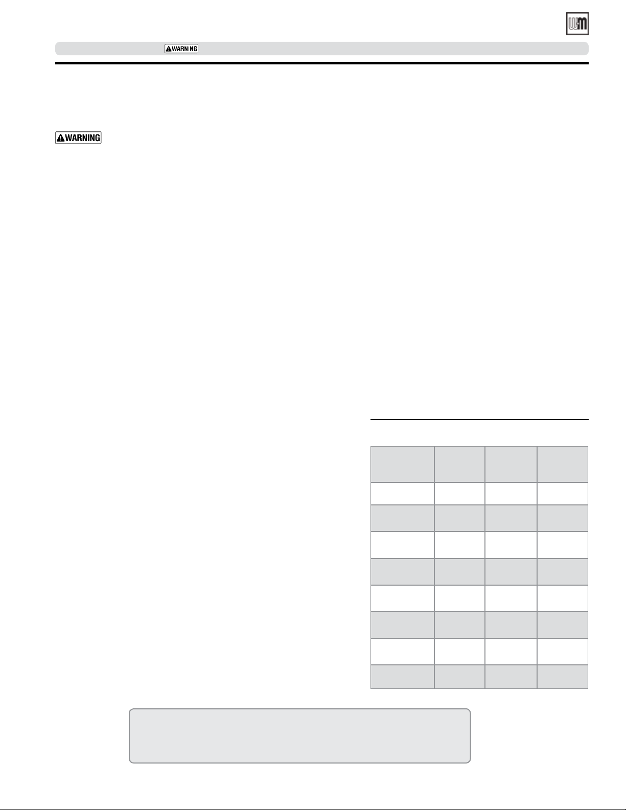
Table 1 Boiler foundation sizes
Boiler
Size
WGO-2
WGO-3
WGO-4
WGO-5
WGO-6
WGO-7
WGO-8
WGO-9
Length
inches
14 22 2
17 22 2
17 22 2
20 22 2
23 22 2
26 22 2
29 22 2
32 22 2
Width
inches
Minimum
height
inches
Part number 550-142-331/0421
9
Page 10
WGO
OIL-FIRED NATURAL DRAFT WATER BOILER — SERIES 4— Boiler Manual
SERVICE TECHNICIAN ONLY — read and follow completely.
Install boiler — Packaged boilers only
Place boiler
1. Remove circulator strapped to pallet.
Circulator will be damaged if not removed before
boiler is lifted from pallet.
2. Remove boiler from pallet.
Do not drop boiler or bump jacket on floor or pallet.
Damage to boiler can result.
Smaller sized boilers may be top heavy. Use caution
when handling to avoid minor personal injury or
property damage.
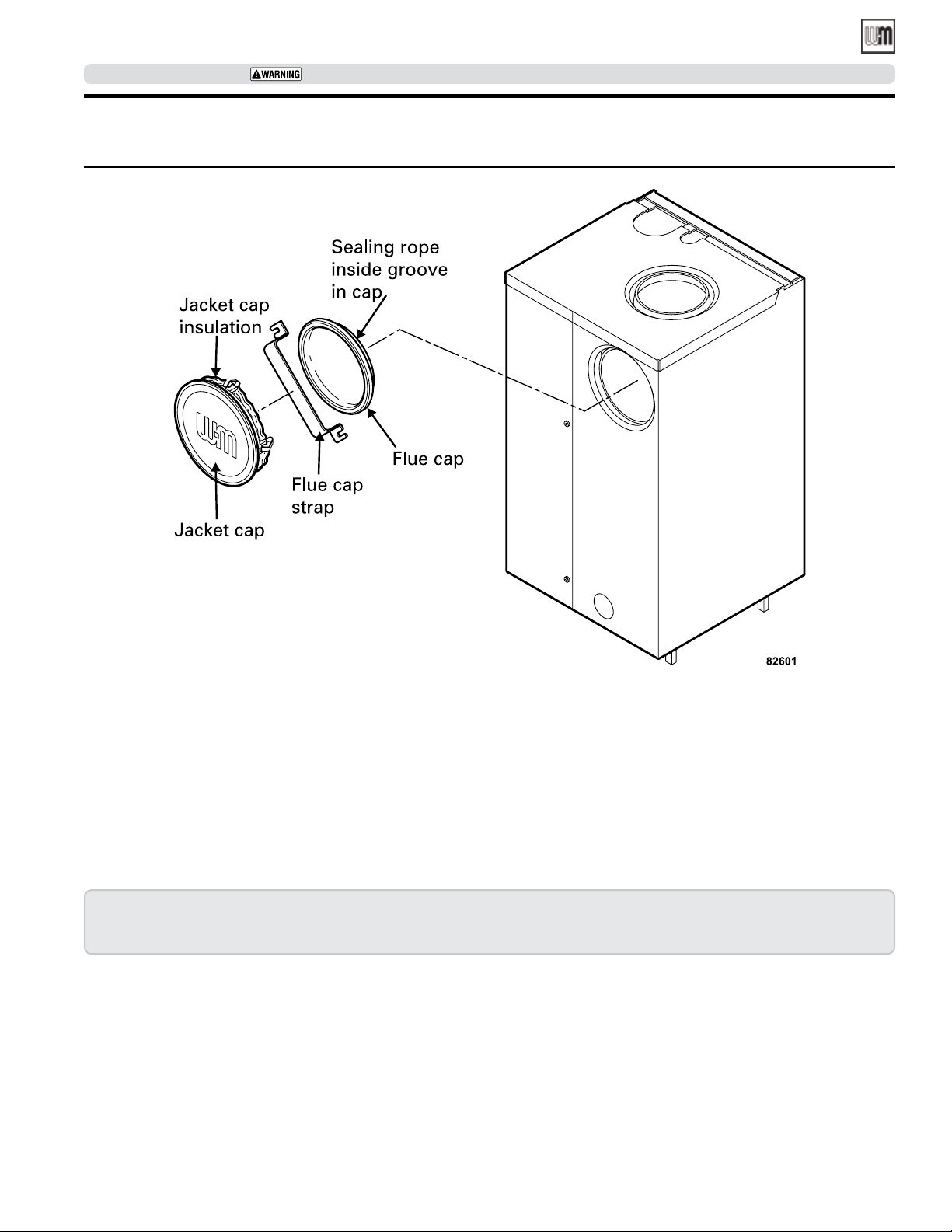
3. Boiler is shipped for back flue outlet. To change to top flue
outlet (see Figure 3, page 11):
a. Remove the jacket cap and the 8.00” diameter piece of
insulation that covers the vent opening from the top
jacket panel.
b. Loosen two (2) screws holding flue cap strap to col-
lector hood. Remove strap and flue cap from opening.
Re-tighten screws.
c. Check rope placement inside flue cap.
(Read
d. Loosen two (2) screws on back flue outlet. Set flue cap on
e. Place the jacket cap insulation disc in the back opening
f. Snap jacket cap in back outlet opening.
4. Check level. Shim legs, if needed.
5. Check for secure placement of insulation on target wall,
chamber floor and burner door.
6. Visually check:
a. Flue collector hood seal.
b. Burner mounting door seal.
under step #6 below).
outlet. Install strap by engaging slots in screws. Tighten
screws. Make sure cap is securely installed.
of the boiler covering the flue cap.
Jacket cap and insulation disc must be in place on
boiler to avoid requiring an 18” minimum clearance
from back of boiler to combustible material.
Obtain gas-tight seal to prevent possible flue gas
leakage and carbon monoxide emissions, which
can lead to severe personal injury or death.
Perform hydrostatic pressure test
1. Remove relief valve installed in boiler.
2. Install air vent in “N” tapping on top boiler.
3. Plug supply and return tappings.
4. Drain valve is already factory-installed.
5. Fill boiler. Vent all air. Pressure test boiler at 1½ times working pressure.
Do not leave boiler unattended. Cold water fill can
expand and damage cast iron, resulting in severe
personal injury, death or substantial property damage.
6. Check for maintained gauge pressure for more than 10 minutes. Visually check for leaks if gauge pressure drops.
7. Drain boiler. Repair leaks if found.
Do not use petroleum-based sealing compounds
to repair leaks. Damage to system components can
result, causing property damage.
8. Retest boiler after repairing leaks.
9. Remove air vent and plugs. Reinstall relief valve.
10
Part number 550-142-331/0421
Page 11
WGO
OIL-FIRED NATURAL DRAFT WATER BOILER — SERIES 4 — Boiler Manual
SERVICE TECHNICIAN ONLY — read and follow completely.
Install boiler — Packaged boilers only (continued)
Figure 3 Change from back flue outlet to top flue outlet (optional)
Part number 550-142-331/0421
Instructions for Packaged boilers continued on page 15.
11
Page 12
WGO
OIL-FIRED NATURAL DRAFT WATER BOILER — SERIES 4— Boiler Manual
SERVICE TECHNICIAN ONLY — read and follow completely.
Install boiler –
Fiberglass wool and ceramic fiber materials are
possible cancer hazards. See warning on page 40.
Semi-packaged and Knocked-down boilers only
Place boiler
Semi-packaged WGO-2 through 6 — position
on site
Smaller sized boilers may be top heavy. Use caution
when handling to avoid minor personal injury or
property damage.
Boiler is shipped for back flue outlet. To change to top flue outlet
(see Figure 4, page 13):
1. Remove the jacket cap and the 8.00” diameter piece of insulation that covers the vent opening from the top jacket panel.
2. Loosen two (2) screws holding flue cap strap to collector
hood. Remove strap and flue cap from opening. Re-tighten
screws.
3. Check rope placement inside flue cap.
(Read above Step #1 on page 13.)
4. Loosen two (2) screws on back flue outlet. Set flue cap on
outlet. Install strap by engaging slots in screws. Tighten
screws. Make sure cap is securely installed.
5. Place the jacket cap insulation disc in the back opening of
the boiler covering the flue cap.
6. Snap jacket cap in back outlet opening.
Jacket cap and insulation disc must be in place on
boiler to avoid requiring an 18” minimum clearance
from back of boiler to combustible material.
Knocked-down WGO-7, 8 & 9 — split the
assembled block for easier handling (see
Figure 4, page 13)
1. Open burner mounting door and, using utility knife, slit floor
insulation at joint to be separated.
2. Remove 5½" draw rod and the longest draw rod from each
side. Pull block apart. Save draw rods, nuts, washers and sealing rings for reassembly.
3. Move divided block to location.
4. Clean port openings with clean rag.
Do not use petroleum-based compounds to clean
openings. Damage to system components can result, causing property damage.
5. Place rings in port openings. If ring slips out of groove, stretch
ring gently for several seconds, then place in groove.
6. Position sections so aligning lugs fit into sockets of next
section. Make sure sealing rope is in good condition and in
position.
7. Oil threads on draw rods. Install washer and nut on end to
be tightened. Use nut only on other end.
8. With wrench at washer/nut end, uniformly tighten nuts starting with 5½" rod at large port, 5½" rod at small port, bottom
long rod and finally top long rod.
9. Torque on both 5½" rods and bottom long rod should be
50-60 ft. lbs.; long top rod should be 20-25 ft. lbs. Do not
back-off nuts.
10. Metal-to-metal contact should be made around port openings. If gap does exist, it should be less than .020". Check
with feeler gauge.
11. If gap around port openings exceeds .020", check for dirt on
port openings, sockets or misaligned lugs. If corrections are
made and gap still exists, contact our Technical Services group
for assistance before continuing installation.
12
Part number 550-142-331/0421
Page 13
WGO
OIL-FIRED NATURAL DRAFT WATER BOILER — SERIES 4 — Boiler Manual
SERVICE TECHNICIAN ONLY — read and follow completely.
Install boiler –
Knocked-down WGO-2 through 9 — install
flue collector hood
Obtain gas-tight seal to prevent possible flue gas
leakage and carbon monoxide emissions, leading
to severe personal injury or death.
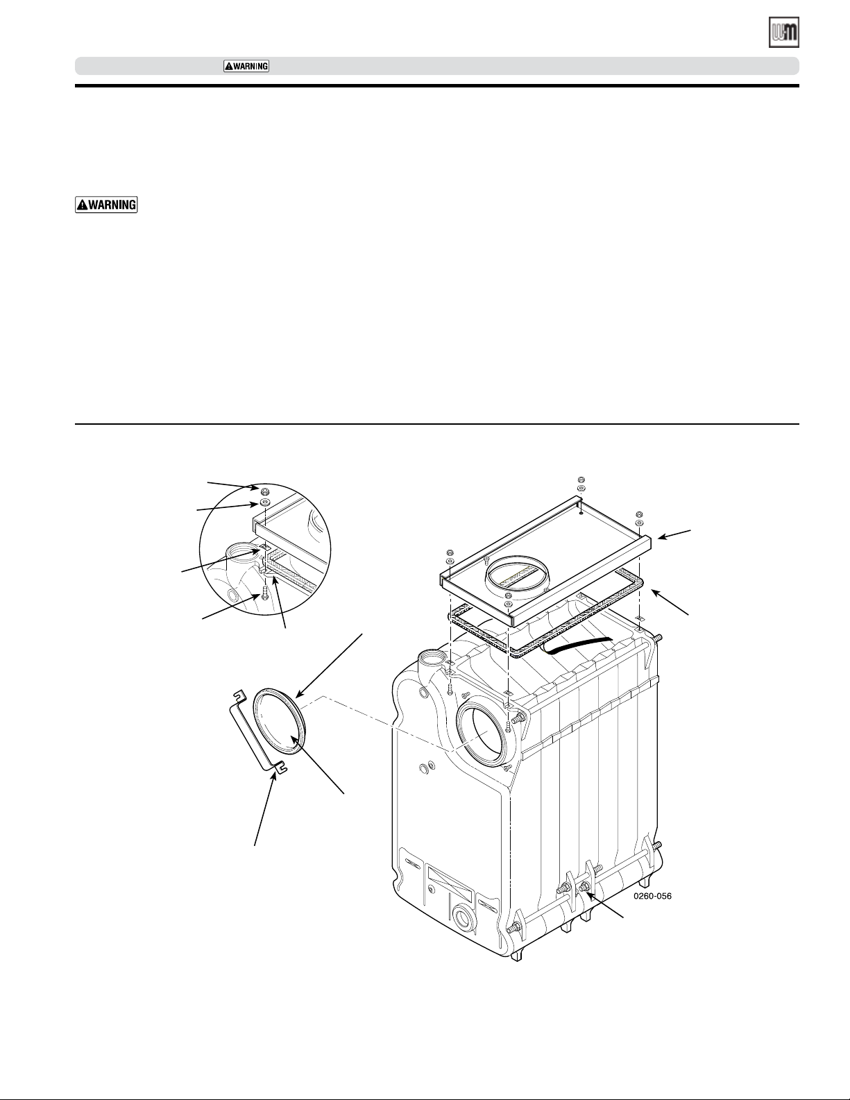
1. Thread Tinnerman clip on screw so that clip fits snugly in
notch of hold-down lug. Screw must not turn.
2. Remove paper on sealing rope. Starting at back section near
flue collar, position sealing rope around top of block with
adhesive side to sections. Do not stretch rope. Make sure rope
ends meet. Trim excess rope.
3. Position flue collector hood on top of boiler sections and
over screws and clips as shown in Figure 4.
Figure 4 Change from back flue outlet to top flue outlet (optional)
Nut
Washer
Tinnerman
clip
Screw
Semi-packaged and Knocked-down boilers only
4. Install washers and nuts. Tighten nuts until collector hood
(see Figure 4 )
5. Flue Cap
6. Check level. Shim legs, if needed.
Sealing
rope in
groove
inside cap
Hold-down
lug
(
continued)
makes contact with Tinnerman clip.
• Back flue outlet boiler — Position flue cap and strap over
opening in flue collector hood. Make sure rope in cap is
in place and in good condition. Tighten strap to hood
with screws provided.
• Top flue outlet boiler — Position flue cap and strap over
opening in back section. Make sure rope in cap is in place
and in good condition. Tighten strap to boiler with screws
provided in section. Install remaining screws in holes in
flue collector hood.
Flue
collector
hood
Sealing
rope with
adhesive
tape
Part number 550-142-331/0421
Flue
cap
Flue cap
strap
Separate
block
here
for easier
handling
13
Page 14
WGO
OIL-FIRED NATURAL DRAFT WATER BOILER — SERIES 4— Boiler Manual
SERVICE TECHNICIAN ONLY — read and follow completely.
Install boiler –
Semi-packaged and Knocked-down boilers only
Perform hydrostatic pressure test
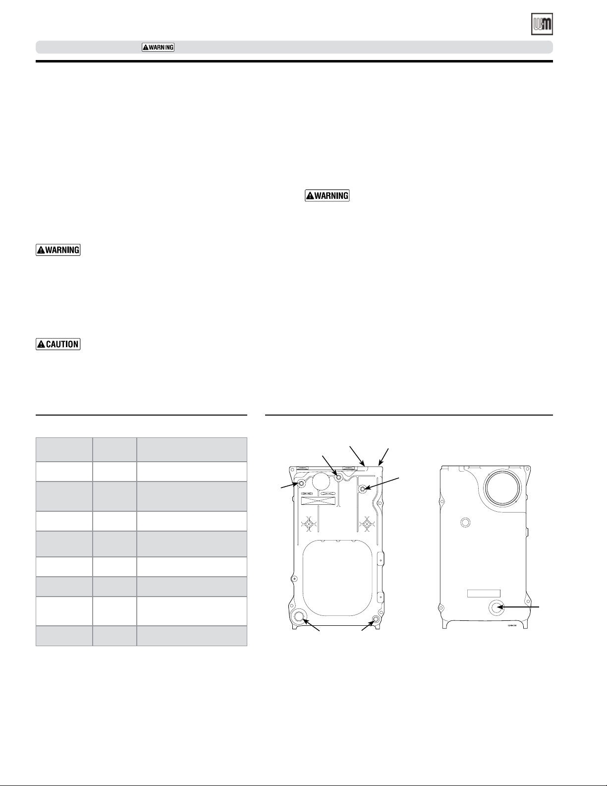
1. See Figure 5 and Control Tapping table to install:
a. Boiler drain.
b. Water pressure gauge (test only). Be sure gauge can
handle test pressure.
c. Air vent in upper “N” tapping.
d. Plugs in remaining tappings.
2. Fill boiler. Vent all air. Pressure test boiler at 1½ times working pressure. For boilers split and reassembled, test between
75 and 85 psig.
Do not leave boiler unattended. Cold water fill
could expand and damage cast iron, resulting in
severe personal injury, death or substantial property damage.
3. Check for maintained gauge pressure for more than 10 minutes. Visually check for leaks if gauge pressure drops.
4. Drain boiler. Repair leaks if found.
Do not use petroleum-based compounds to repair
leaks. Damage to system components can result,
causing property damage.
5. Re-test boiler after repairing leaks.
(
continued)
6. Remove pressure gauge, air vent and plugs from tappings
used for controls.
7. Visually check:
a. Sealing rope placement.
b. Metal-to-metal contact around port openings.
c. Flue collector hood seal.
d. Burner mounting door seal.
Obtain gas-tight seal to prevent possible flue gas
leakage and carbon monoxide emissions, which
can lead to severe personal injury or death.
Install jacket
(knocked-down boilers only sizes 7 through 9 only)
Before installing jacket, remove burner mounting door.
See jacket instructions for details.
Install boiler controls
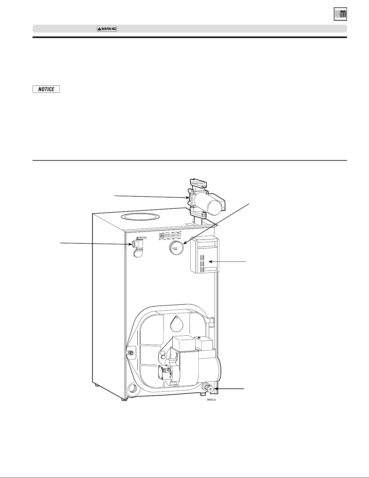
See Control Tapping Table 2 and Figures 5 and Figure 6, page 15
to install controls.
1. Install limit control. If not furnished, use high limit with
maximum 220°F setting.
2. Affix Consumer Protection (CP) number label(s) on jacket
front panel.
Table 2 Control tappings
Location Size Function
B1 1½" Return piping
B2 1½"
C 1½" Supply piping
E3 ¼"
H ¾" Drain valve
L ¾" High limit control
N ½"
R1 ¾" Relief valve
Alternate return piping
for A/B WGO
Pressure-temperature
gauge
Air vent or expansion
tank piping
Figure 5 Control tapping locations
N
E3
R1
B1 H
Front section
C
L
WGO-2
B2
Back section
14
Part number 550-142-331/0421
Page 15
WGO
OIL-FIRED NATURAL DRAFT WATER BOILER — SERIES 4 — Boiler Manual
SERVICE TECHNICIAN ONLY — read and follow completely.
Install burner — all boilers
Install burner
(also refer to instructions packed with burner)
Use only burners specified for use on Weil-McLain
oil boilers. Contact individual burner manufacturers for proper burner selections.
For burners with OEM welded flanges:
1. Secure mounting flange and gasket to burner mounting
door. Use three (3) bolts provided.
2. Open door to verify secure placement of insulation on target
wall, chamber floor and burner mounting door.
Figure 6 Water boiler controls
Circulator
Relief
valve
3. Securely close door and tighten nut.
For burners without OEM welded flanges:
1. Secure universal mounting flange and gasket to burner mounting door. Use three (3) bolts provided.
2. Secure burner on flange with three (3) bolts.
3. Position burner so end of air tube is level to 1½-degree tilt down
toward chamber. Open door to verify burner position. End
of air tube should be flush to ¼” recessed from inside wall of
burner door refractory. Check for secure placement of insulation on target wall, chamber floor and burner mounting door.
4. Securely close door and tighten nut.
Water
pressure-temperature
gauge
Limit control / low water cut-off
Drain valve
Part number 550-142-331/0421
15
Page 16
WGO
OIL-FIRED NATURAL DRAFT WATER BOILER — SERIES 4— Boiler Manual
SERVICE TECHNICIAN ONLY — read and follow completely.
Connect breeching
General chimney requirements
• Designed for natural draft firing. Connect boiler to vertical
chimney.
• Insufficient draft can cause flue gas leakage and carbon monoxide
emissions, which will lead to severe personal injury or death.
• Use vent material approved by local codes for oil-fired burners.
In their absence, refer to:
• NFPA 31 – latest edition, Installation of Oil-Burning Equip-
ment.
• NFPA 211 – latest edition, Standard for Chimneys, Fireplaces,
Vents and Solid Fuel Burning Appliances.
• In Canada, refer to CSA B139, Installation Code for Oil-
Burning Equipment.
• NFPA 211 requires chimney to be lined before connected to boiler.
• Inspect existing chimney before installing new boiler. Failure to do
any of the following will result in severe personal injury or death:
• Clean chimney, including removal of blockage.
• Repair or replace damaged pipe or liner.
• Repair mortar and joints.
• To prevent downdrafts, extend chimney at least 3 feet above
highest point where it passes through roof and 2 feet higher than
any portion of building within 10 feet. Increase chimney crosssectional area and height at least 4% per 1,000 feet above sea level.
• Minimum clearances from vent pipe to combustible material:
• 6 inches — Type “L” double-wall vent
• 9 inches — Single-wall vent
• Minimum chimney sizes should be used.
Oversized chimneys, outside masonry chimneys and/or
derated inputs can result in condensation in chimney.
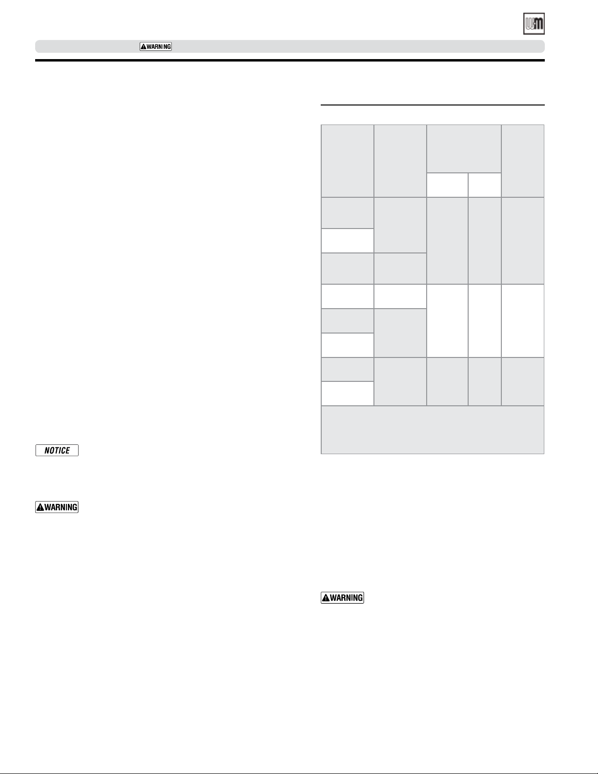
Table 3 Minimum chimney sizes
Minimum
AHRI
chimney size
Rect. Round
8" x 8"
(Note 1) 6" 15'
8" x 8"
(Note 1) 7" 15'
8" x 12"
(Note 2)
Boiler
Size
WGO-2
WGO-3
WGO-4
WGO-5
WGO-6
WGO-7
WGO-8
WGO-9
NOTE:
Minimum
breeching
diameter
(Note 3)
5"
6"
6"
7"
7"
1. 6¾" x 6¾" inside liner.
2. 6½" x 10½" inside liner.
3. Flue collar on boiler is 7" diameter
Minimum
chimney
height
7" 20'
Connect breeching:
Long horizontal breechings, excessive number of tees
and elbows or other obstructions restricting combustion
gas flow can result in possibility of condensation, flue
gas leakage and carbon monoxide emissions, which can
lead to severe personal injury or death.
1. Install two (2) flue pipe brackets.
2. Connect full-sized breeching when possible. See Minimum Chimney Size, see Table 3.
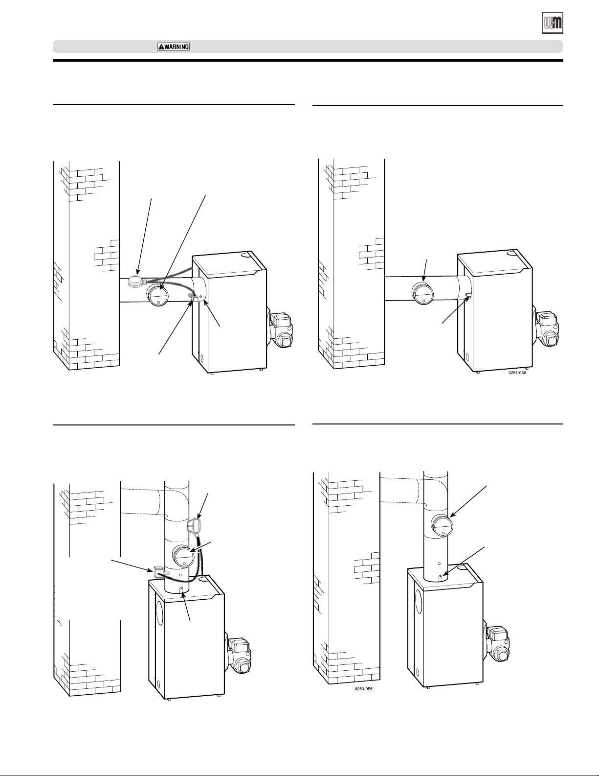
• Back outlet — see Figures 7 and 9, page 17.
• Top outlet — see Figures 8 and 10, page 17.
3. Connection must be made above bottom of chimney to avoid
blockage. Breeching must not enter chimney far enough to cause
obstruction. Use thimble or slip joint where breeching enters
chimney to allow removal for cleaning.
4. When burner and boiler are properly installed, draft overfire will
be approximately -0.01” to -0.02” W.C. Install barometric control
in breeching, per control manufacturer’s instructions, when excess
draft needs to be relieved or to comply with applicable codes and
regulations. Use draft gauge to adjust proper opening.
16
5. An induced draft fan for the chimney may be necessary if:
• Excessive resistance to flow of combustion gases
can be expected.
• Cross-sectional area of chimney is smaller than
minimum recommended.
• Chimney height is less than recommended.
Seal all vent joints. Interlock burner with fan
operation.
6. Boiler models ending in “D”, such as WGO-3D, require
the installation of the Field Controls OVD-7 automatic
damper kit, Weil-McLain part number 381-800-515.
Refer to Figures 7 and 8, page 17.
Part number 550-142-331/0421
Page 17
WGO
OIL-FIRED NATURAL DRAFT WATER BOILER — SERIES 4 — Boiler Manual
SERVICE TECHNICIAN ONLY — read and follow completely.
Connect breeching (continued)
Figure 7 Back Outlet Breeching for models which
require a vent damper.
OVD Damper
(Required)
BVSS
(WMO-1)
(Integrated with damper)
BVSS must be installed
upstream of the barometric
damper.
Typical location for
barometric control
(Also see control
manufacturer’s
instructions)
Flue pipe
bracket
(One on each
side of pipe)
0251-056_OVD
Figure 9 Back outlet breeching connection for models
which do not require a vent damper.
Typical location for
barometric control
(Also see control
manufacturer’s
instructions)
Flue pipe
bracket
(One on each
side of pipe)
Figure 8 Top Outlet Breeching for models which require
a vent damper.
OVD
Damper
(Required)
Typical location for
barometric control
BVSS
(WMO-1)
(Integrated with damper)
BVSS must be installed
upstream of the
barometric damper.
Flue pipe
bracket
(One on each
side of pipe)
0250-056_OVD
(Also see control
manufacturer’s
instructions)
Figure 10 Top outlet breeching connection for models
which do not require a vent damper.
Typical location for
barometric control
(Also see control
manufacturer’s
instructions)
Flue pipe bracket
(One on each
side of pipe)
Part number 550-142-331/0421
17
Page 18
WGO
OIL-FIRED NATURAL DRAFT WATER BOILER — SERIES 4— Boiler Manual
SERVICE TECHNICIAN ONLY — read and follow completely.
Connect water piping
General piping information
• All Packaged WGO boilers are shipped with an installed
combination temperature limit control/low water cut-off.
• If installation is to comply with ASME, an additional high
temperature limit is needed. If installation is to comply with
Canadian requirements, an additional high temperature limit
maybe needed. Consult local inspector. Install control in supply piping between boiler and isolation valve. Set control to
a minimum of 20°F above set point of combination control.
Maximum allowable set point is 220°F. Wire control as shown
on wiring diagram.
• Use back flow check valve in cold water supply as required
by local codes.
Install piping
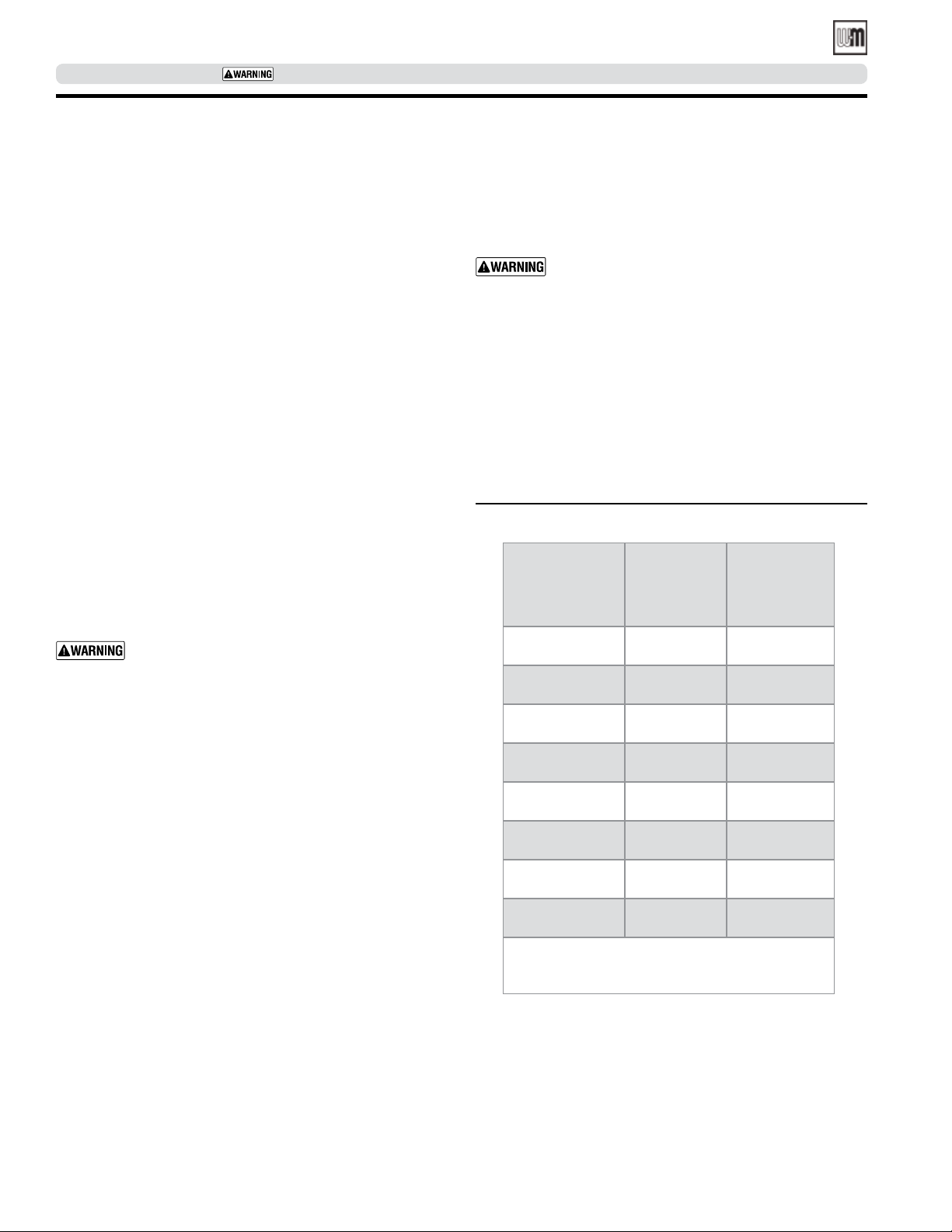
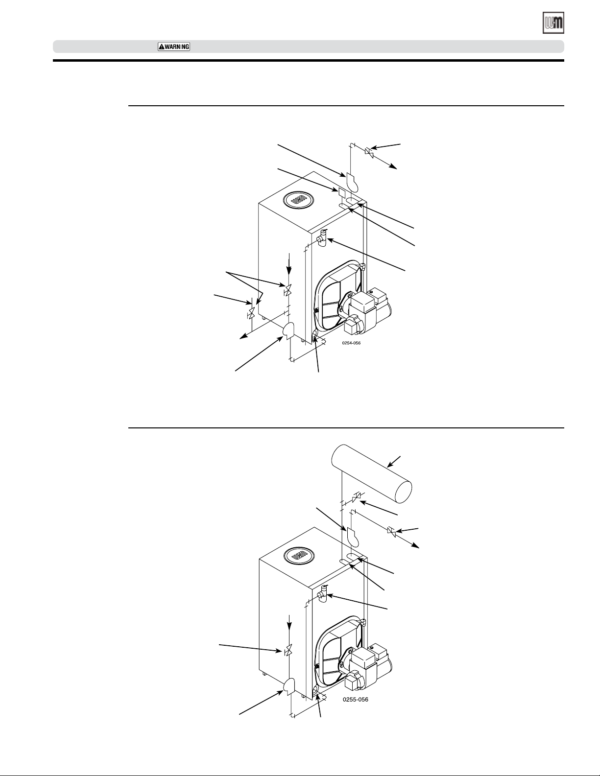
• See Figures 11 or Figure 12, page 19, and Table 4 for nearboiler piping and single-zone piping. See page 20 to complete multiple-zone piping or page 21 to complete piping for
systems operating below 140°F.
• For multiple-boiler piping, contact Weil-McLain Technical
Services for assistance, if required.
• Install relief valve vertically in “R1” tapping on front of boiler.
See Figure 11 or Figure 12 and also refer to tag attached to
relief valve for manufacturer’s instructions.
Pipe relief valve discharge line near floor close to
floor drain to eliminate potential of severe burns.
Do not pipe to any area where freezing could occur. Do not plug, valve or place any obstruction in
discharge line.
CLOSED expansion tank
(Figure 12, page 19)
• Ensure expansion tank size will handle boiler and system
water volume and temperature.
Undersized expansion tanks cause system water to
be lost from relief valve and makeup water added
through fill valve. Eventual section failure can result.
• Connect tank from “N” tapping shown in Figure 12, page 19
to expansion tank. Use ½" NPT piping. Pitch any horizontal
piping up towards tank 1 inch per 5 feet of piping.
To connect WGO boilers to indirect-fired
water heaters
Install and wire per water heater manual provided with water
heater.
Table 4 Water piping sizes
Boiler
Size
WGO-2 1" 1"
WGO-3 1¼" 1¼"
WGO-4 1¼" 1¼"
To system From system
DIAPHRAGM expansion tank
(Figure 11, page 19)
• Make sure expansion tank size will handle boiler and system
water volume and temperature. Tank must be located near
boiler before inlet to circulator. See tank manufacturer’s
instructions for details.
• Undersized expansion tanks cause system water to be lost
from relief valve and makeup water added through fill valve.
Eventual section failure can result.
• Install automatic air vent in “N” tapping as shown in Figure 11.
18
WGO-5 1½" 1½"
WGO-6 1½" 1½"
WGO-7 1½" 1½"
WGO-8 2" 2"
WGO-9 2" 2"
* All piping sizes based on 20°F
temperature rise through boiler.
Part number 550-142-331/0421
Page 19
WGO
OIL-FIRED NATURAL DRAFT WATER BOILER — SERIES 4 — Boiler Manual
SERVICE TECHNICIAN ONLY — read and follow completely.
Connect water piping (continued)
Figure 11 Piping with DIAPHRAGM expansion tank
Circulator
Automatic
air vent
From
Isolation
valve
Cold water
fill
To diaphragm
expansion tank
and fittings
Circulator
(Alternate circulator location)
system
Isolation
valve
To
system
“C” tapping
“N” tapping
Relief
valve
“B1” tapping
Figure 12 Piping with CLOSED expansion tank
Circulator
From
system
Isolation
valve
Circulator
(Alternate circulator
location)
“B1” tapping
Closed type expansion tank
Cold water fill
Isolation valve
To system
“C” tapping
“N” tapping
Relief
valve
Part number 550-142-331/0421
19
Page 20
WGO
OIL-FIRED NATURAL DRAFT WATER BOILER — SERIES 4— Boiler Manual
SERVICE TECHNICIAN ONLY — read and follow completely.
Connect water piping (continued)
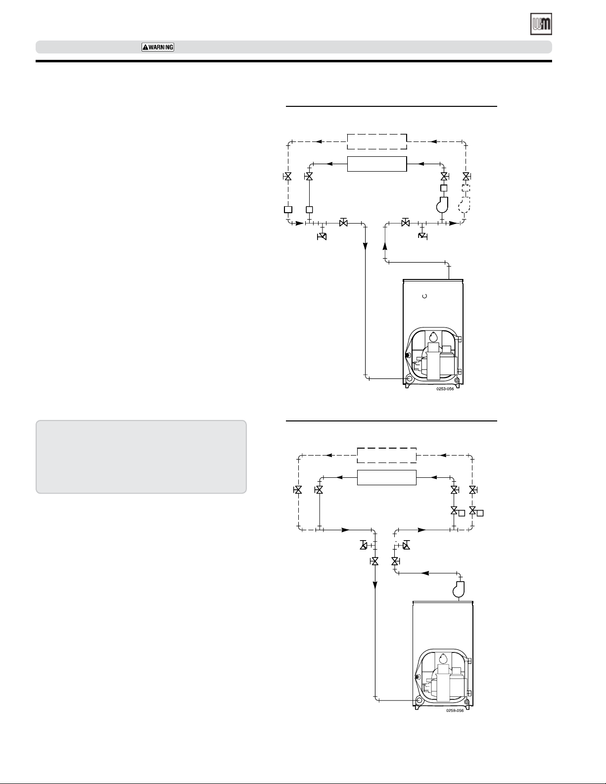
Piping MULTIPLE ZONES
Follow instructions on page 18 and page 19 to install
piping near boiler.
See Figure 13 or Figure 14 to complete installation.
Zoning with circulators:
1. Size each circulator to individual circuit requirements.
2. Install balancing valves to adjust flow to distribute
heat to all zones.
3. Separate relay is required for each circulator.
Zoning with zone valves:
1. Install balancing valves to adjust flow to distribute
heat to all zones.
2. Separate transformer is required to power zone
valves. Refer to manufacturers installation instructions for wiring or contact our Technical Services
group for assistance.
3. Pressure bypass valve recommended on zone valve
systems to prevent excessive flow in a single zone
or water hammer when valves close.
Figure 13 Multiple zoning with CIRCULATORS
Zone 2
Zone 1
1
2
1
5
1
2
3
1
5
Legend
1 Isolation valve
2 Flow control valve
3 Circulator
4 Zone valve
5 Drain valve
Figure 14 Multiple zoning with ZONE VALVES
Zone 2
Zone 1
1
5
1
5
1
1
4
20
Part number 550-142-331/0421
Page 21
WGO
OIL-FIRED NATURAL DRAFT WATER BOILER — SERIES 4 — Boiler Manual
SERVICE TECHNICIAN ONLY — read and follow completely.
Connect water piping (continued)
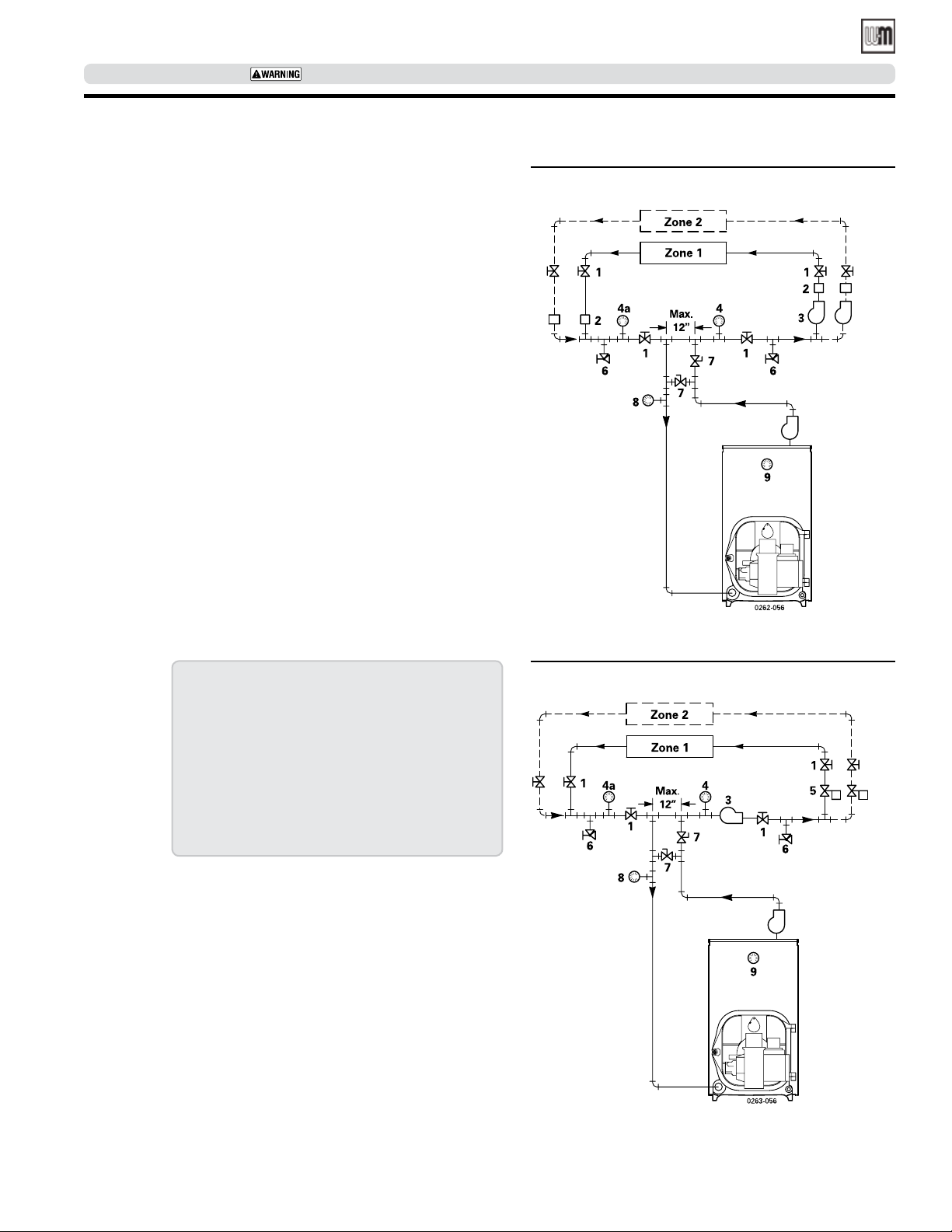
Piping for systems requiring
temperatures below 140°F
In most systems, this type of piping is not required. If
system water temperature requirements are less than
140°F, such as radiant panels or converted gravity systems, use piping as shown in Figure 15 or Figure 16. If
system piping is plastic without an oxygen barrier, a
heat exchanger must be used.
Figure 15 Piping with CIRCULATORS
Legend
1 Isolation valve
2 Flow control valve
3 Circulator
4 System temperature
gauge
5 Zone valve
6 Drain valve
7 System temperature
valves
Adjust valves so that:
- the temperature at
gauge 8 is at least 140°F
- the temperature at
gauge 9 is at least 160°F
8 Blend temperature
gauge
9 Boiler temperature
gauge
Figure 16 Piping with ZONE VALVES
Part number 550-142-331/0421
21
Page 22
WGO
OIL-FIRED NATURAL DRAFT WATER BOILER — SERIES 4— Boiler Manual
SERVICE TECHNICIAN ONLY — read and follow completely.
Connect water piping
(continued)
Use with refrigeration systems
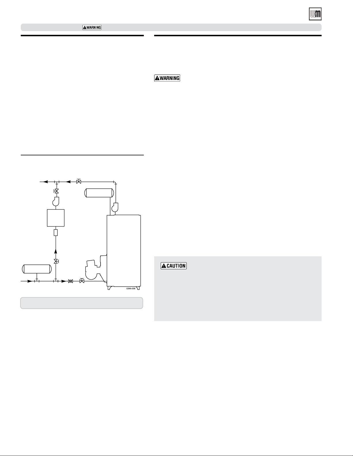
• Install boiler so that chilled medium is piped in
parallel with heating boiler. Use appropriate valves
to prevent chilled medium from entering boiler.
Consult AHRI Installation and Piping Guides.
• If boiler is connected to heating coils located in
air handling units where they can be exposed to
refrigerated air, use flow control valves or other
automatic means to prevent gravity circulation
during cooling cycle.
Figure 17 Use with refrigeration system
1
Supply
1
Circ.
Chiller
Exp. tank
Circ.
Connect wiring
General wiring requirements
Electric shock hazard – Can cause severe personal injury or
death if power source, including service switch on boiler, is
not disconnected before installing or servicing.
• Installations must follow these codes:
• National Electrical Code, ANSI/NFPA 70, – latest edition and any
additional national, state or local codes.
• In Canada, CSA C22.1 Canadian Electrical Code Part 1 and any
local codes.
• Wiring must be NEC Class 1. If original wire as supplied with boiler
must be replaced, type 105°C wire or equivalent must be used. Supply wiring to boiler and additional control wiring must be 14 gauge
or heavier.
• Provide electrical ground at boiler as required by codes.
Thermostat wiring
• Install thermostat on inside wall away from influences of drafts, hot
or cold water pipes, lighting fixtures, television, sun rays or fireplaces.
• Follow instructions with thermostat. If it has a heat anticipator, set
heat anticipator in thermostat to match power requirements of equipment connected to it. Boiler wiring diagrams give setting for standard
equipment.
Strainer
Exp. tank
1 Isolation valve 2 Balancing valve
1
1
2
Zone Valve Wiring
DO NOT connect directly from 3-wire zone
valves to the T-T terminals on the boiler
using 3-wire zone valves, install an isolation relay. Connect the zone valve end switch wires to the isolation relay
coil. Connect the isolation relay contact across the boiler
T-T terminals. Failure to comply can result in damage
to boiler components or cause unreliable operation,
resulting in possible severe property damage.
4- wire zone valves may be connected directly to the boiler control.
. When
22
Part number 550-142-331/0421
Page 23
WGO
OIL-FIRED NATURAL DRAFT WATER BOILER — SERIES 4 — Boiler Manual
SERVICE TECHNICIAN ONLY — read and follow completely.
Connect wiring (continued)
General wiring
• Packaged boilers have harnesses furnished.
• For Semi-packaged and Knocked-down boilers, trim kits
are furnished with burner and limit harnesses integrated
with Hydrolevel control.
• All field-provided high voltage wiring must be sheathed
in flexible metal conduit.
• Connect incoming line voltage “HOT” wire to service
switch, and neutral wire to white wire. Field-install equipment ground wire to green wire with wire nut inside
Hydrolevel control.
• Service switch is integrated into the Hydrolevel control.
• Some local codes may require an emergency shut-off
switch installed at a location away from boiler. Follow
local codes.
Burner wiring
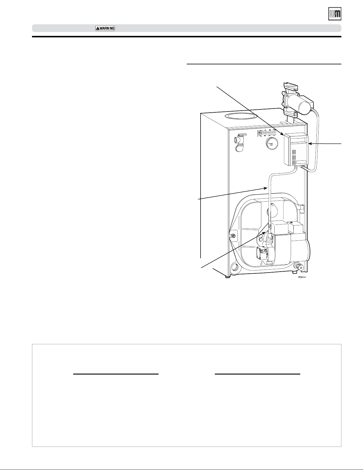
• Burner harness incorporates a disconnect plug, providing a convenient way to disconnect wiring when burner
mounting door is opened.
• All Packaged boilers have a power disconnect plug installed
on combination limit control.
• The burner is provided with a burner disconnect plug as
shown in Figure 18. For burners in which the disconnect
plug is not factory-wired, connect the threaded conduit
coupling of the disconnect plug wire harness (P/N 591391-850, included in water trim carton) to the burner
housing and route the wires to make all connections in
burner junction box as shown in boiler wiring diagram.
High temperature limit
• To comply with ASME, UL 726 or Canadian requirements,
an additional high temperature limit is needed.
• Install the secondary control in the supply piping between
boiler and isolation valve.
• Set the control to a minimum of 20˚F above the set point
of the combination control.
• The maximum allowable set point is 220˚F.
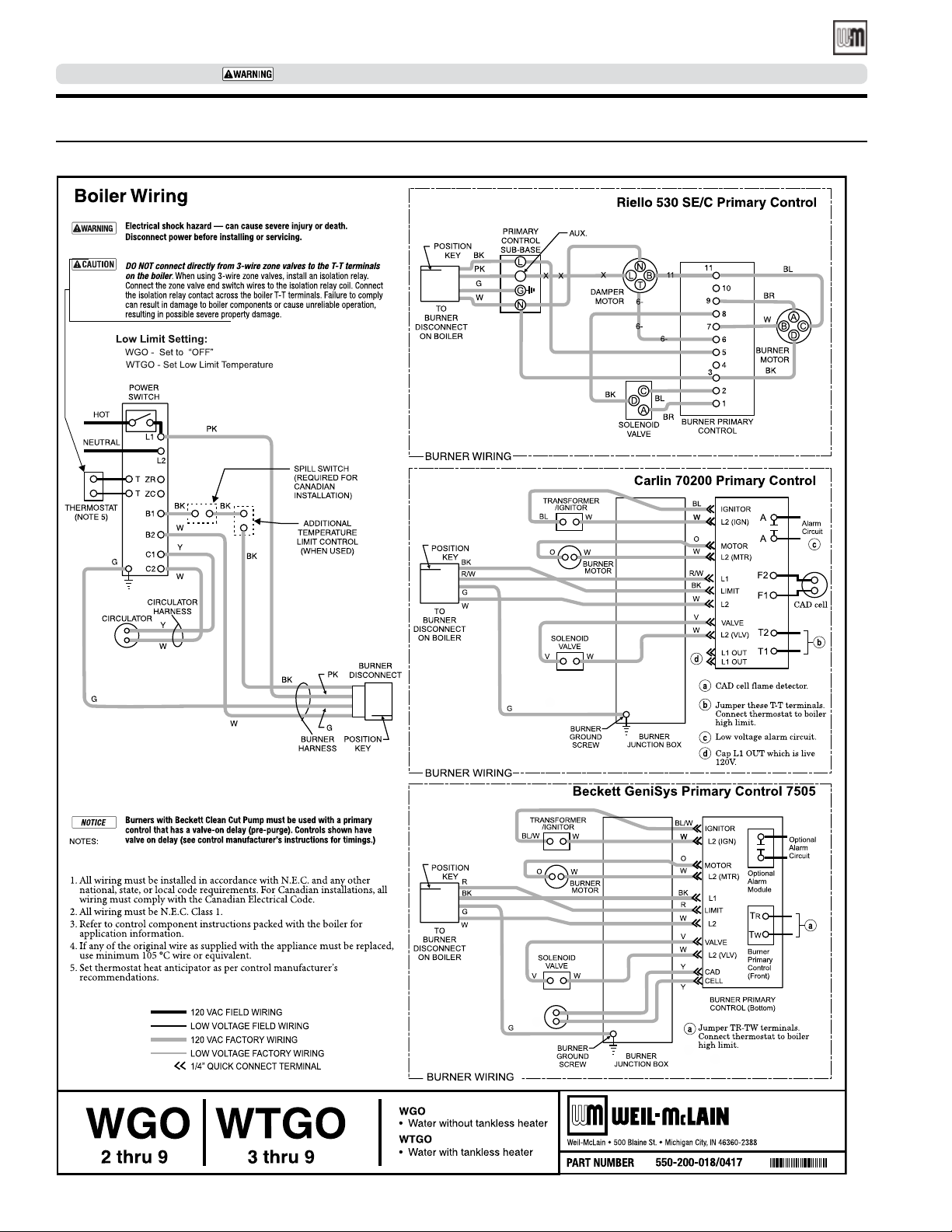
• Wire the control as shown on page 24.
Figure 18 Boiler wiring for forced hot water
Limit control
Service
switch
on
control
Burner
wiring
harness
Burner
disconnect
plug
THE LIMIT CONTROL SUPPLIED WITH THE BOILER MUST BE SET-UP WITH THERMAL PREPURGE
OR THERMAL TARGETING ACTIVE UNLESS EXEMPTED BELOW:
In accordance with Section 303 of the
2007 Energy Act
with a feature that saves energy by reducing the boiler water temperature as
the heating load decreases. This feature
is equipped with an override which is
provided primarily to permit the use of
an external energy management system
that serves the same function.
Part number 550-142-331/0421
, this boiler is equipped
IMPORTANT
THIS OVERRIDE MUST NOT BE USED UNLESS AT LEAST ONE OF THE
FOLLOWING CONDITIONS IS TRUE:
•An external energy management system is installed that reduces the boiler water temperature as the heating load decreases.
•This boiler is not used for any space heating.
•This boiler is part of a modular or multiple boiler system having a total input of
300,000 BTU/hr or greater.
•This boiler is equipped with a tankless coil (not applicable to WGO boilers).
23
Page 24
WGO
OIL-FIRED NATURAL DRAFT WATER BOILER — SERIES 4— Boiler Manual
SERVICE TECHNICIAN ONLY — read and follow completely.
Connect wiring (continued)
Figure 19 Wiring diagram
24
Part number 550-142-331/0421
Page 25
WGO
OIL-FIRED NATURAL DRAFT WATER BOILER — SERIES 4 — Boiler Manual
SERVICE TECHNICIAN ONLY — read and follow completely.
Connect wiring —
blocked vent shutoff switch option
Blocked vent shutoff switch
In Canada, blocked vent shutoff switch kit
(see parts list page 34) must be installed.
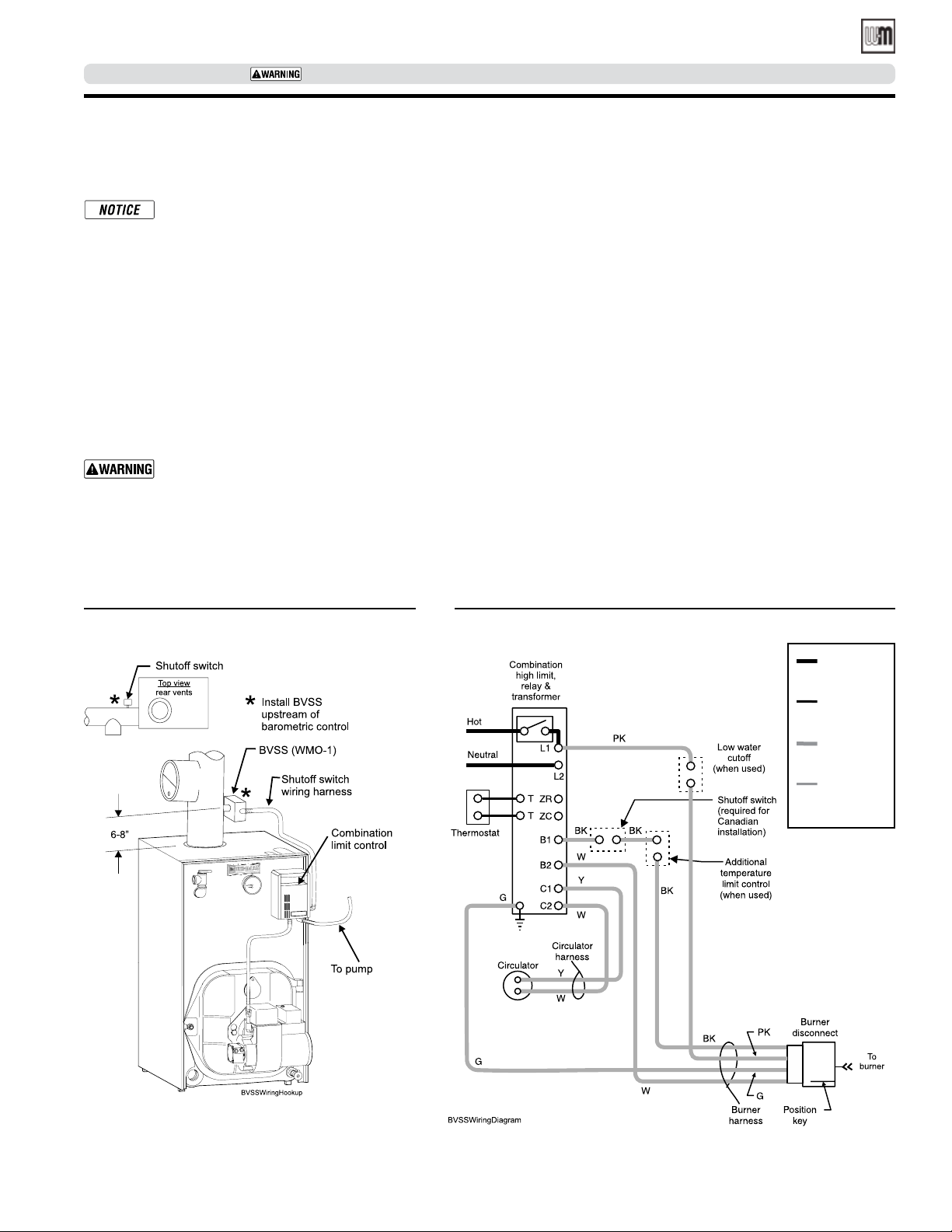
See Figure 20.
When using the OVD damper kit, the
BVSS is required, and is integrated into
the damper harness wiring.
When using the BVSS without the OVD
damper, the BVSS is wired directly to the
Combination limit control as follows.
The wiring diagram in Figure 21 shows
boiler wiring only up to the burner
disconnect. For additional information,
refer to manufacturer’s instructions.
Electric shock hazard – Turn off electri-
cal power supply at service entrance panel
before making any electrical connections
to avoid possible electric shock hazard.
Failure to do so can cause severe personal
injury or death.
After installing BVSS switch, proceed as follows:
1. Disconnect power.
2. Install Shutoff Switch (BVSS) Wiring Harness (P/N 591-391-942,
which is included in BVSS kit P/N 591-624-650) as follows:
a. Remove cover from BVSS Box.
b. Install straight fitting end of the harness on the BVSS Box. Install
elbow (90º) end fitting on the right side of the Hydrolevel control.
c. Install both the fork ends to the screw terminals on the BVSS
Switch as per the wiring diagram, (see Figure 21).
d. Replace BVSS box cover.
e. Locate Combination Control, remove cover, and disconnect red
wire from “B1” terminal.
f. If red wire from Step “e” has uninsulated female end, replace it
with insulated female end as supplied in kit.
g. Connect female end of Shutoff Switch BVSS Harness (blue wire)
to “B1” terminal.
h. Connect male end of Shutoff Switch BVSS Harness to the red
wire removed in Step “e”.
i. Replace Combination Control Cover.
3. Turn on power and verify safe operation of the appliance.
4. Restore boiler to normal operation.
Figure 20 Blocked vent shutoff switch
installation
Figure 21 BVSS wiring diagram
120 vac
field wiring
Low voltage
field wiring
120 vac
factory wiring
Low voltage
factory wiring
Part number 550-142-331/0421
25
Page 26
WGO
OIL-FIRED NATURAL DRAFT WATER BOILER — SERIES 4— Boiler Manual
SERVICE TECHNICIAN ONLY — read and follow completely.
Connect oil pipingConnect wiring - vent
damper
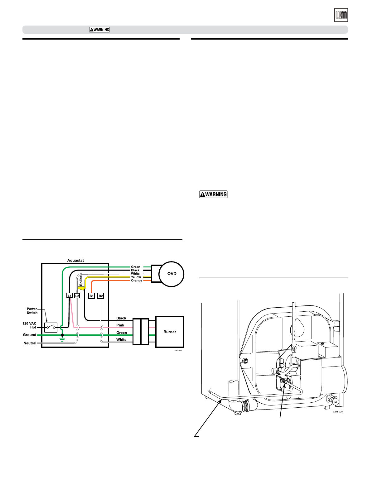
1. WGO Boiler models ending in “D”, such as WGO-3D, require the installation of the Field Controls OVD-7 damper,
Weil-McLain part number 381-800-515, sold separately.
2. To configure the WGO boiler as a model ending in “RD” and
to obtain the Energy Star labels, install the specific Energy
Savings Damper Kit listed in Table 7 on page 36.
3. When installing the boiler, wire all controls from vent damper
and thermal switch in accordance with the OVD damper
manual and the following wire diagram.
4. Connect damper wires to the boiler as follows:
a. Remove black wire (burner disconnect harness) from
the B1 terminal, and connect that wire to the yellow
wire from damper, using a wire nut.
b. Connect the orange wire from the damper to the B1
screw terminal.
c. Connect the black wire from the damper to the L1
screw terminal.
d. Connect the white wire from the damper to the L2
screw terminal.
e. Connect the green wire from the damper to ground.
Figure 22 OVD Vent damper wiring diagram
General oil piping requirements
• Location and installation of oil tanks, oil piping and
burners must follow:
• NFPA 31- latest edition, Standard for the Installation
of Oil-Burning Equipment.
• In Canada, CSA B139, Installation of Oil-Burning
Equipment.
• Local codes and regulations.
• Information provided with burner and fuel pump.
• If any part of fuel oil tank is above level of burner, instal-
lation of an anti-siphon device is highly recommended
to be used to prevent flow of oil in case of oil line break.
• Support oil lines as required by codes.
• Make tank connections with swing joints or copper tubing
to prevent breaking in case the tank settles. Make swing
joints so they will tighten as tank settles. Non-hardening
pipe joint compounds should be used on all threads.
Do not use Teflon tape as an oil pipe sealant. It
can cause valves to fail, creating hazards. Do not
use compression fittings.
• Underground pipe must be run in a casing to prevent oil
leaking into ground or under floor. Check local codes for
information.
Oil piping connection at burner
See Figure 23 for recommended connection at burner, allowing burner mounting door to swing open completely for
servicing.
Figure 23 Recommended oil piping connection to
See local codes for appropriate
arrangement and piping of filter
control valves, etc., back to oil tank.
burner
Flare fitting
26
Part number 550-142-331/0421
Page 27
WGO
OIL-FIRED NATURAL DRAFT WATER BOILER — SERIES 4 — Boiler Manual
Start-up
SERVICE TECHNICIAN ONLY — read and follow completely.
Fill the system
1. Close manual and automatic air vents and boiler drain cock.
2. Fill to correct system pressure. Correct pressure will vary
with each installation. Normal cold water fill pressure for
residential systems is 12 psig. Boiler water pH 7.0 to 8.5 is
recommended.
Failure to maintain recommended pH level can
cause section failure and leaks.
3. Open automatic air vent one turn.
4. Open other vents.
a. Starting on the lowest floor, open air vents one at a time
until water squirts out. Close vent.
b. Repeat with remaining vents.
5. Refill to correct pressure.
When using antifreeze
Do not use automotive, ethylene glycol, undiluted
or petroleum-based antifreeze. Severe personal
injury, death or substantial property damage can
result.
• Use antifreeze especially made for hydronic systems. Inhibited propylene glycol is recommended.
• 50% solution provides protection to about -30°F. Do not
exceed 50% mixture.
• Local codes may require back-flow preventer or actual disconnect from city water supply.
• Determine quantity according to system water content.
Boiler water content is listed on back cover of manual. Percent of solution will affect sizing of heat distribution units,
circulator and expansion tank.
• Follow antifreeze manufacturer’s instructions.
• Do not add cold water to hot boiler. Thermal shock can
cause sections to crack.
To place in operation
1. Verify boiler is filled with water.
2. Open burner mounting door and verify rear target wall, floor
and burner door insulations are in proper position.
3. Verify burner mounting door is closed tightly and burner
wiring harness is connected to Hydrolevel control.
4. Factory burner adjustment and settings may not be suitable
for specific job conditions. See Close Clearance Installation,
page 31.
A burner nozzle change may be required - refer to the
burner instructions or boiler’s rating label for correct
nozzle selection
Make final burner adjustments using combustion
test equipment to assure proper operation. Do not
fire boiler without water. Sections will overheat,
damaging boiler and resulting in substantial property damage.
5. Vent air from system. Repeat steps 4 and 5 under “Fill the
system.” Air in system can interfere with water circulation
and cause improper heat distribution.
6. Check boiler and system piping for leaks. See “Tips for water
systems” on page 4.
7. Inspect breeching and venting for proper operation.
Part number 550-142-331/0421
27
Page 28
WGO
OIL-FIRED NATURAL DRAFT WATER BOILER — SERIES 4— Boiler Manual
SERVICE TECHNICIAN ONLY — read and follow completely.
Check-out procedure
Check off steps as completed
Boiler and heat distribution units filled with water?
Automatic air vent, if used, opened one full turn?
Air purged from system? Piping checked for leaks?
Air purged from oil piping? Piping checked for leaks?
Flue cap in place and tightened? Burner door closed, sealed
and nut tight? Burner plugged in and service switch on?
Obtain gas-tight seal to prevent possible flue gas
leakage and carbon monoxide emissions, leading
to severe personal injury or death.
Proper draft and burner flame? Final adjustment made with
combustion test equipment?
Test limit control: While burner is operating, move indica-
tor on limit control below actual boiler water temperature.
Burner should go off while circulator continues to operate.
Raise setting on limit control above water temperature and
burner should re-ignite.
operation as outlined by the manufacturer. Burner should be
operating and should go off when controls are tested. When
controls are restored, burner should re-ignite.
Limit control set to system temperature requirements
(max. 220°F)?
For multiple zones, flow adjusted to distribute heat in all
zones?
Thermostat heat anticipator setting (if available) set properly?
Refer to “Connect wiring,, “ page 22 .
Boiler cycled with thermostat? Raise to highest setting and
verify boiler goes through normal start-up cycle. Lower to
lowest setting and verify boiler goes off.
Observed several operating cycles for proper operation?
Set room thermostat(s) to desired room temperature?
Completed Installation and Service Certificate below?
Reviewed pages 1–7 with owner or maintenance person and
instructed person to keep for future reference?
Test additional field-installed controls: If boiler has a low
water cutoff, additional high limit or other controls, test
Returned all instructions provided with boiler to its envelope
and placed with boiler for future reference?
Installation and service certificate
Installation and service certificate
Date Installed: __________________ ____________
Boiler Model Number: ________ S eries: ____________
Consumer Protection (CP) Number(s): _________
Measured Btu or GPH Input: ________________
Installer: ________________________________________________________________________________________________
(Company) (Address) (Phone)
_________________________________________
Installation instructions have been followed.
Check-out procedure has been performed.
Above information is certified to be correct.
Information received and left with owner/
maintenance person.
(Installer’s Signature)
28
Part number 550-142-331/0421
Page 29
WGO
OIL-FIRED NATURAL DRAFT WATER BOILER — SERIES 4 — Boiler Manual
SERVICE TECHNICIAN ONLY — read and follow completely.
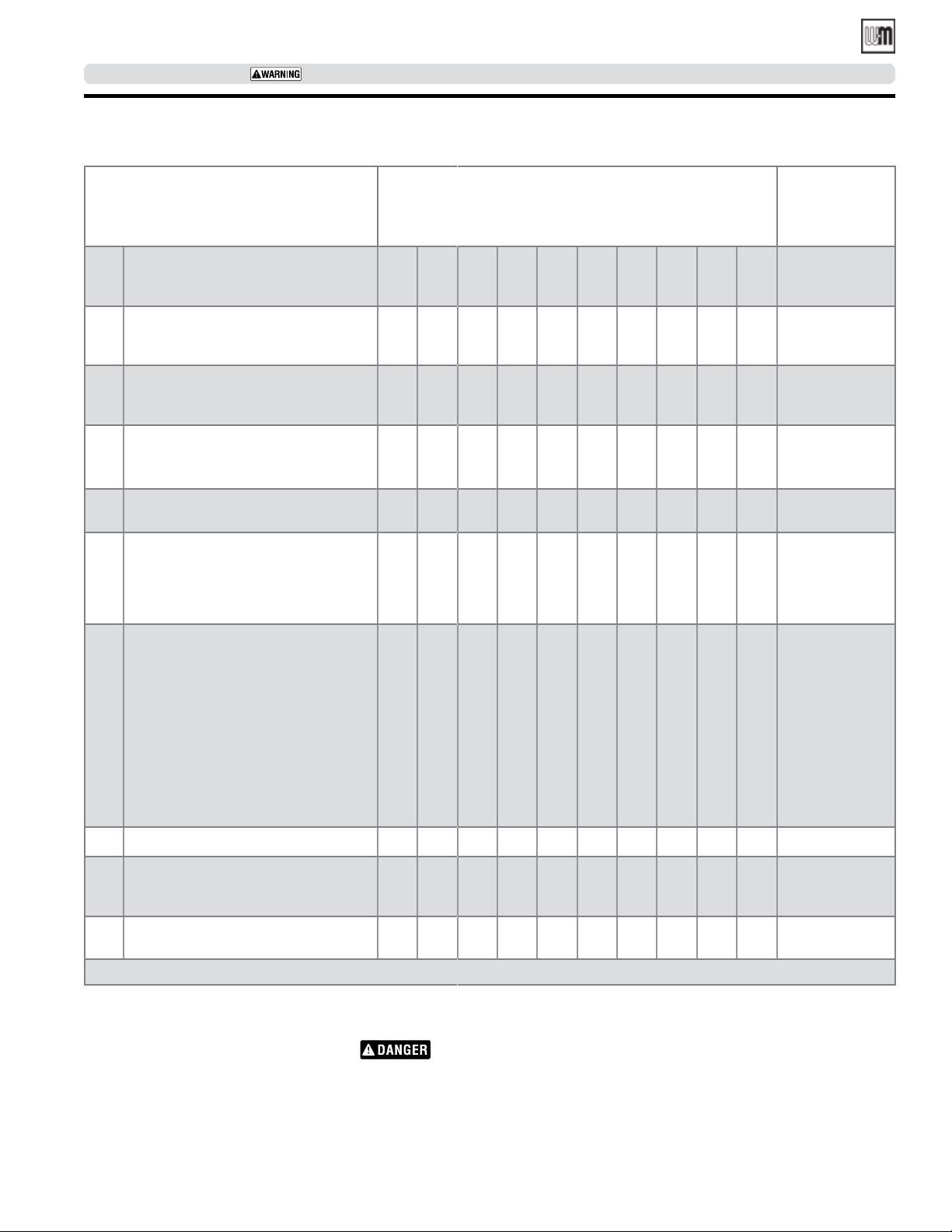
Annual service check list
Annual Service Call
Checklist
(follow in order listed below)
Check that boiler area is free from
combustible materials, gasoline and
1
other flammable vapors and liquids.
Check for and remove any obstruction
to combustion and ventilation air flow
2
to boiler.
Check breeching and chimney or vent
for obstructions, damage, etc. Repair
3
or replace as necessary.
Clean boiler flue ways. Figure 24, page 30.
4
Dates Comments
Perform service on relief valve and
5
circulator. See page 30.
Check boiler and piping for leaks and
repair if found. Check for leaks at
tankless heater plate. Tighten nuts only
6
if leaks are found (for WGO torque to
20-25 ft.lbs.).
Inspect and adjust burner. See burner
manual and:
• change nozzle.
• check ignition electrode settings.
• clean blower housing and wheel.
7
• make sure blower wheel turns
freely.
• oil burner motor if required.
• clean air inlet.
• clean or change fuel filter and
strainer.
Make sure boiler is filled with water.
8
Start unit and verify combustion settings with combustion test equipment.
9
See page 31.
Verify operation of all controls on
10
boiler. See page 28.
Any parts of the boiler furnished by Weil-McLain must be replaced by parts listed in Weil-McLain Boiler and Repair Parts Book.
Controls requiring annual service
Water Relief Valve
Check operation of water relief valve.
Follow instructions on label fastened to
relief valve.
Part number 550-142-331/0421
Scald potential. Do not check
operation of relief valve unless discharge piping has
been installed according to
Boiler Manual. If piping is
not in place, a qualified service technician must properly install piping.
Circulator
Follow oil-lubricating instructions on circulator. Over-oiling will damage circulator.
Water-lubricated circulators do not need
oiling.
29
Page 30
WGO
OIL-FIRED NATURAL DRAFT WATER BOILER — SERIES 4— Boiler Manual
SERVICE TECHNICIAN ONLY — read and follow completely.
Detailed service procedures
Cleaning boiler flue ways
Make sure all electrical connections to boiler are turned
off and wait until boiler is warm, not hot, before cleaning. Failure to do so will result in severe personal injury,
death or substantial property damage.
1. Top flue boilers -remove breeching and jacket top panel.
Rear flue boilers - remove jacket top panel.
2. Remove flue collector hood, saving hardware for reassembly.
3. Shut off oil valves. Arrange drip pans under the areas of oil piping
that will be disconnected. Disconnect oil line at burner so that
you can swing open the door completely.
4. Line combustion chamber floor with newspaper to catch any
soot that will be loosened in the cleaning process.
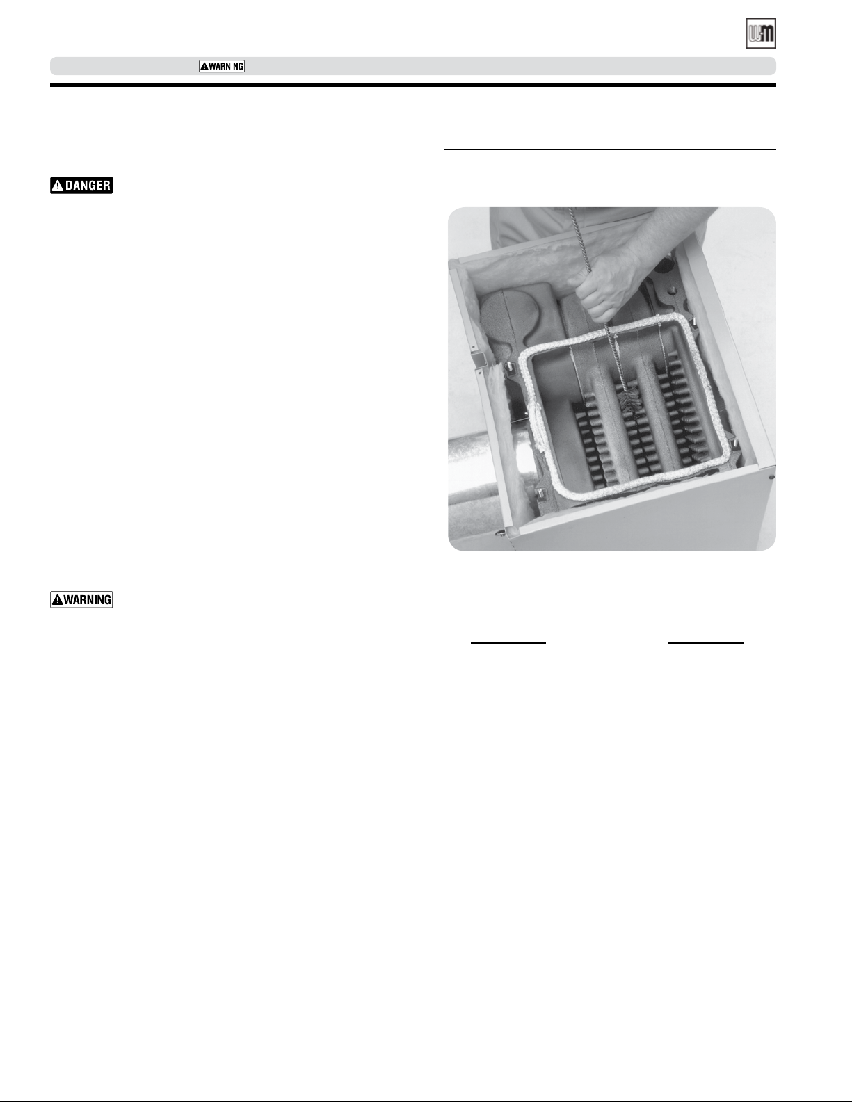
5. Starting at the top of the boiler, use a wire flue brush to thoroughly clean between all pins at all angles. Be careful not to
damage side walls of rear refractory.
6. Move to the bottom of the flue ways and clean up between the
sections to reach pins left uncleaned in step #5.
7. Once the flue ways are cleaned, carefully remove the paper from
the floor of the combustion chamber.
8. Verify sealing rope around flue area is intact. Visually check condition
and position of insulation in combustion chamber floor, and the refractories at the rear of boiler and in the burner mounting door. Replace
any parts as necessary.
9. Close burner mounting door and tighten nut securely. Place
flue collector hood on top of boiler. Secure with hardware from
step #2.
Maintain a gas-tight seal to avoid possible flue gas
leakage and carbon monoxide emissions, which can
lead to severe personal injury or death.
10. Check breeching for sooting and clean if necessary. Install jacket
top panel and breeching.
11. Reconnect oil line and all electrical connections.
General description of control operation
Automatic air vent
Air is released when cap is unscrewed one turn. If air vent leaks, remove small cap on top of vent, push in stem of valve and then release
to clean valve seat. Screw cap completely on, then unscrew one turn.
Figure 24 Thoroughly clean flue ways between all
pins at all angles. Start on top of boiler,
finish from the bottom.
The limit control supplied with the boiler must be setup with thermal prepurge or thermal targeting active
unless exempted below:
IMPORTANT
THIS OVERRIDE MUST NOT BE USED UNLESS AT
LEAST ONE OF THE FOLLOWING CONDITIONS IS TRUE:
• An external energy management system is installed that reduces
the boiler water temperature as the heating load decreases.
• This boiler is not used for any space heating.
• This boiler is part of a modular or multiple boiler system having
a total input of 300,000 BTU/hr or greater.
• This boiler is equipped with a tankless coil (not applicable to
WGO boilers).
Temperature limit control
If high boiler water temperature occurs, control shuts down burner, but
allows circulator to run as long as there is a call for heat. Limit should
be set higher than temperature needed for the system.
Maximum limit setting is 220°F.
2007 Energy Act Compliance
In accordance with Section 303 of the 2007 Energy Act, this
boiler is equipped with a feature that saves energy by reducing
the boiler water temperature as the heating load decreases. This
feature is equipped with an override which is provided primarily
to permit the use of an external energy management system that
serves the same function.
30
Water relief valve
Provides discharge if boiler pressure exceeds 30 psig.
Circulator
Circulator provides forced water circulation through boiler
and piping system.
Pressure-temperature gauge
Provides reading of boiler pressure and temperature. Maximum boiler pressure is 50 psig, maximum water temperature
is 220°F. Temperature will vary according to system and daily
heating demands. The range will be from room temperature
up to limit control setting.
Part number 550-142-331/0421
Page 31
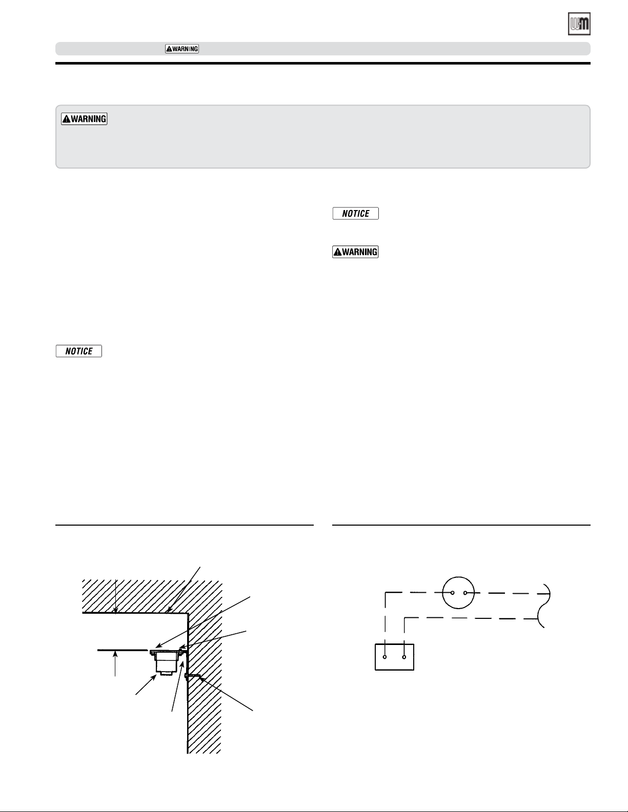
WGO
OIL-FIRED NATURAL DRAFT WATER BOILER — SERIES 4 — Boiler Manual
SERVICE TECHNICIAN ONLY — read and follow completely.
Close clearance installation
To provide close clearances as described on pages 31 and 32:
Obtain the Close Clearance Kit, Weil-McLain Part No. 386-500-050. Install the kit as described below.
Failure to use kit or install as described can result in a fire hazard, causing severe personal injury, death or
substantial property damage.
Close clearance installation
Substitute these instructions for corresponding material in
manual. All other procedures and practices must remain the same.
Recommended service and minimum clearances shown on
page 8 should be used where possible. Where closer clearances
are required:
• Top of boiler — If less than 24" available, provide removable
surface to allow for cleaning boiler flue ways.
• Right or left side — Minimum 2 inches.
• Front — Minimum 2 inches from burner.
• Double-wall flue pipe to combustible surface — as listed in
Table 5, page 32 and Figures 25 through Figure 29, page 32.
Jacket cap must be in place on boiler to avoid requir-
ing an 9" minimum clearance from back or top of
boiler to combustible material. Flue pipe clearances
must take precedence over jacket clearances.
1. Install boiler using clearances described at left.
2. Install barometric control 18-20 inches from boiler in
breeching.
3. Attach manual reset temperature switch near upper surface
of enclosed area. See Figure 25.
4. Wire switch in series with thermostat. See Figure 26.
5. Provide two combustion/ventilation openings when installing in confined space. Size opening 140 sq. in. (1000 Btu)
per 1 GPH input. Locate openings near top and bottom of
enclosed space.
Burner adjustments
A burner nozzle change may be required - refer to
the burner instructions or boiler’s rating label for
correct nozzle selection
Final burner adjustments must be made using com-
bustion test equipment to assure proper operation.
Do not fire boiler without water or sections will
overheat.
1. Refer to burner manual for start-up.
2. Allow boiler to heat to design condition.
3. Burner should be adjusted to 13% CO2 or less with a smoke
level of zero and over-fire of -0.01” to -0.02”. Re-adjust burner
combustion to account for environmental conditions. Actual
CO2 value will vary and should be adjusted for clean and safe
combustion operation. Seasonal variations as well as sufficient combustion air supply can affect proper combustion
and boiler performance. The burner should only be adjusted
by a service professional with appropriate instrumentation.
Figure 25 Manual reset temperature switch location Figure 26 Manual reset temperature switch wiring
Manual reset
temperature switch
44156
1 to 5
inches
Manual reset
temperature
switch
Area above boiler
Part number 550-142-331/0421
Bracket
Combustible surface
#6 X ½" Phillips
Sheet metal
screw
Thermostat
#10 X ½" Phillips
sheet metal screw
31
Page 32
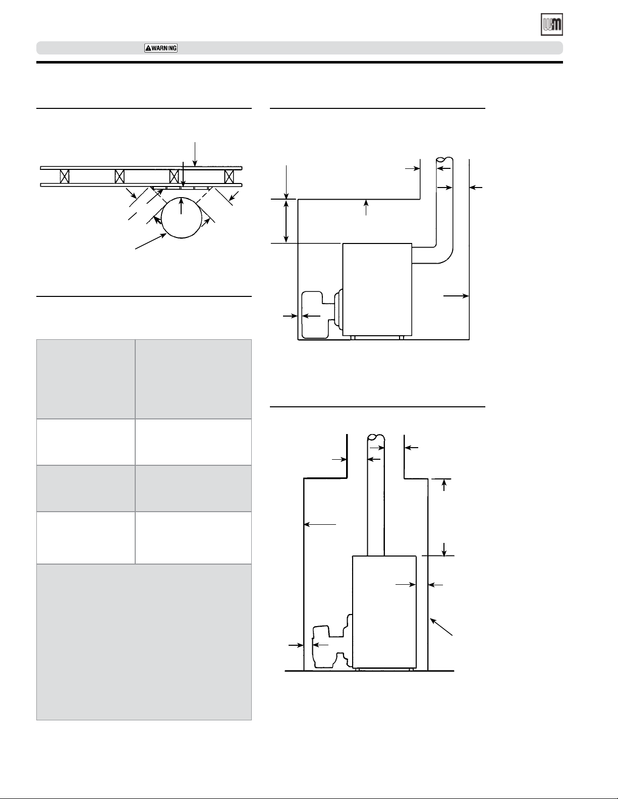
WGO
OIL-FIRED NATURAL DRAFT WATER BOILER — SERIES 4— Boiler Manual
SERVICE TECHNICIAN ONLY — read and follow completely.
Close clearance installation (continued)
Figure 27 Flue pipe clearances Figure 28 Back vent clearances
Combustible surface
A
Protection
Type “L” double-wall
vent piping
Type “L”
double-wall
vent pipe
6"
6"
Table 5 Protection required for clearances
less than 6 inches from double wall
vent pipe*
Dimension A
When desired minimum
clearance from
Type “L” double-wall
vent pipe to combustible
surface is:
3"
2"
3"
Use the following
protection**:
½” thick insulation board
***
over one-inch glass fiber
or mineral wool batts+
24 gauge sheet metal
with
one-inch ventilated air
space
½” thick insulation board
***
with one-inch ventilated
air space
24" For servicing
or min. 2" For close
clearances
Combustible
surface
2"
Note: 2" min. on sides
Figure 29 Top vent clearances
A
A
Combustible
surface
A
A
Combustible
surface
24" For
servicing
or min. 2"
For close
clearances
* All clearances measured from outer surface of
equipment to combustible surface, not to the
protection used.
** Apply to combustible surface unless otherwise
noted. Cover all surfaces as specified in Table and
Figure 24. Thicknesses are minimum.
*** Factory-fabricated board made of non-
combustible materials, normally fibers, having
thermal conductivity in range of one (Btu-inch)/
(hr./sq. ft./°F) or less.
+ Mineral wool batts (blanket or board), having min.
density of 8 lb./ft3 and a min. melting point of
1500°F.
Other dimensions available. Refer to NFPA-31.
32
2"
2"
Combustible
surface
Note: 2" min. on sides
Part number 550-142-331/0421
Page 33
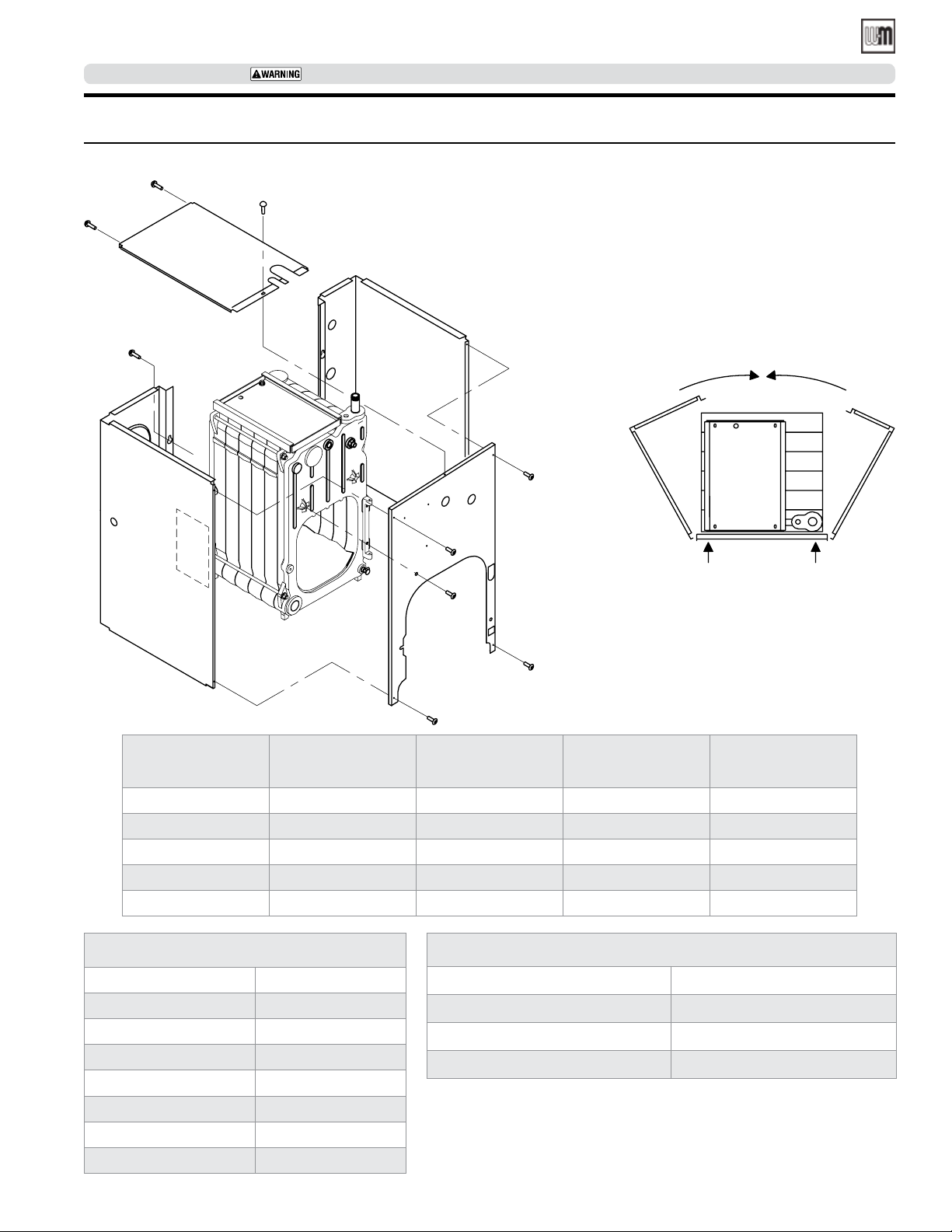
WGO
OIL-FIRED NATURAL DRAFT WATER BOILER — SERIES 4 — Boiler Manual
SERVICE TECHNICIAN ONLY — read and follow completely.
Replacement parts
Figure 30 WGO Boiler jacket for Series 4
Boiler
Size
WGO-2 381-355-937 381-355-938 381-355-982 381-355-943
WGO-3 381-355-937 381-355-939 381-355-974 381-355-944
WGO-4 381-355-937 381-355-940 381-355-975 381-355-945
WGO-5 381-355-937 381-355-941 381-355-976 381-355-946
WGO-6 381-355-937 381-355-942 381-355-977 381-355-947
Complete Jacket cartons
3 section WGO-2 416-700-460
3 section WGO-3 416-700-461
4 section 416-700-462
5 section 416-700-463
6 section 416-700-464
7 section 416-700-465
8 section 416-700-466
9 section 416-700-467
Part number 550-142-331/0421
Jacket panel with
insulation — front
Left side and
rear
Common jacket parts for all boilers
Plastic ue cap cover w/insulation 560-917-105
Jacket hardware kit 386-700-853
Touch up paint, Cloud spray can 381-359-278
Touch up paint, Slate spray can 384-000-141
Right side and
rear
Top panel with
cap
33
Page 34
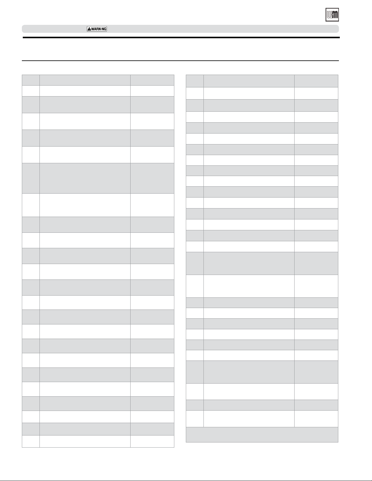
WGO
OIL-FIRED NATURAL DRAFT WATER BOILER — SERIES 4— Boiler Manual
SERVICE TECHNICIAN ONLY — read and follow completely.
Replacement parts (continued)
Table 6 WGO Section and flue collector part numbers for Series 4
Item
Description Part no.
A Regular front section 7022 316-700-215
Wide intermediate section
B
(WGO-3) 7010
Narrow intermediate section
B
7015
Intermediate section w/draw rod
C
lugs 7016
Back section w/7" ue, supply &
D
2" return 7027
Section replacement kit
(for 1 joint, includes seals, rope,
E
adhesive and collector hood
hardware) front or back section
Section replacement kit (for 2
joints, includes seals, rope and
adhesive) intermediate section
Section assembly, for WGO-2 with
jacket & collector hood installed
Section assembly, for WGO-3 with
jacket & collector hood installed
Section assembly, for WGO-4 with
jacket & collector hood installed
Section assembly, for WGO-5 with
jacket & collector hood installed
Section assembly, for WGO-6 with
jacket & collector hood installed
Section assembly only, for WGO-2
316-700-075
316-700-065
316-700-070
316-700-235
386-700-852
386-700-851
386-701-022
386-701-023
386-701-024
386-701-025
386-701-026
386-700-973
Item
Description Part no.
F Collector hood kit for WGO-5* 386-700-338
F Collector hood kit for WGO-6* 386-700-339
F Collector hood kit for WGO-7* 450-020-188
F Collector hood kit for WGO-8* 450-020-189
F Collector hood kit for WGO-9* 450-020-190
G Tie rod 1/2 x 51/2 (WGO-7, 8, 9) 560-234-464
G Tie rod 1/2 x 103/4 (WGO-2 & 7) 560-234-491
G Tie rod 1/2 x 12 (WGO-7) 560-234-492
G Tie rod 1/2 x 14 (WGO-3, 4, 8, 9) 560-234-470
G Tie rod 1/2 x 15 (WGO-9) 560-234-495
G Tie rod 1/2 x 17 (WGO-5) 560-234-472
G Tie rod 1/2 x 20 (WGO-6) 560-234-534
G Tie rod 1/2 x 231/4 (WGO-7) 560-234-538
G Tie rod 1/2 x 263/8 (WGO-8) 560-234-542
G Tie rod 1/2 x 291/2 (WGO-9) 560-234-497
Combustion chamber kit (rear &
H
frt. ref., door ref. blanket, rope,
386-700-355
blanket & water glass)
Burner mounting door assembly
(door, obs. port, rope, ins. &
386-700-358
pins)
J Burner mounting door 7070 330-054-302
Section assembly only, for WGO-3
Section assembly only, for WGO-4
Section assembly only, for WGO-5
Section assembly only, for WGO-6
Section assembly only, for WGO-7
Section assembly only, for WGO-8
Section assembly only, for WGO-9
386-700-978
386-700-980
386-700-981
386-700-982
386-700-662
386-700-663
386-700-664
F Collector hood kit for WGO-2* 386-700-336
F Collector hood kit for WGO-3* 386-700-337
F Collector hood kit for WGO-4* 386-700-337
34
K Door hinge 7054 330-054-300
L Door refractory 386-700-359
M Door refractory blanket 591-222-115
N Observation port shutter 460-039-867
P Door seal rope 5' 590-735-104
3/8" Glass rope for collector
Q
hood
590-735-109
(7' for largest size hood)
Flue cap assembly
R
(cap, strap, rope & screws)
386-700-344
Flue brush 123D 591-706-214
Blocked vent shutoff switch
(Canada only)
* Includes ue cap assembly, rope and hardware for
installation.
Part number 550-142-331/0421
511-624-650
Page 35
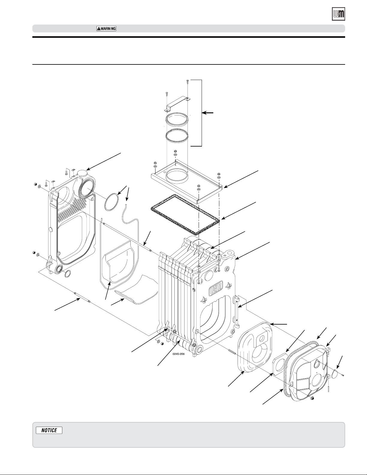
WGO
OIL-FIRED NATURAL DRAFT WATER BOILER — SERIES 4 — Boiler Manual
SERVICE TECHNICIAN ONLY — read and follow completely.
Replacement parts (continued)
Figure 31 WGO Section and flue collector parts for Series 4
D
E
R
F
Q
G
H
G
G
C
B
A
K
H
H
H
J
N
Repair parts must be purchased through Weil-McLain for the specific boiler as indicated in the list below. Results
from using modified or other manufactured parts will not be covered by warranty and may damage boiler or impair
operation.
Part number 550-142-331/0421
L
M
P
35
Page 36
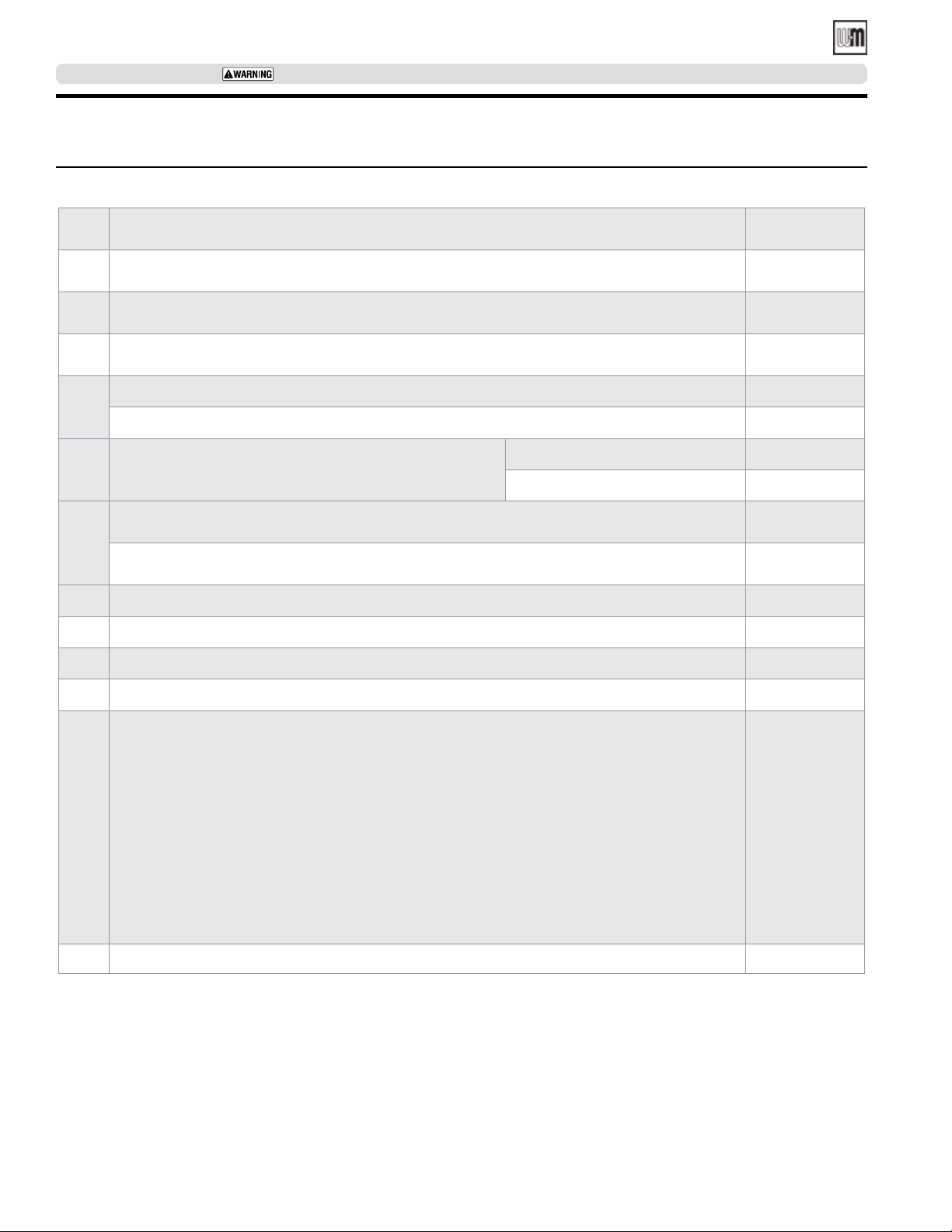
WGO
OIL-FIRED NATURAL DRAFT WATER BOILER — SERIES 4— Boiler Manual
SERVICE TECHNICIAN ONLY — read and follow completely.
Replacement parts (continued)
Table 7 WGO Trim part numbers for Series 4
Item Description Part no.
Combination pressure-temperature gauge kit, 60° – 360° F., 0 - 75 psi,
1
31/8" dia., 1/4" NPT, short shank, with 1/4" x 1/2" reducing bushing
ASME pressure relief valve, set to relieve at 30 PSIG, 3/4" male inlet,
2
3/4" female outlet
Electronic aquastat, high limit or combination high/low limit, with LWCO, high limit 100°– 220°,
3
low limit 110°- 200°, circulator amps: 5.8 FLA, anticipator: 0.2 amps
Drain cock, 3/4" NPT, 11/2" shank 511-210-423
4
Drain cock, 3/4" NPT 511-246-392
WGO 2 - 4 – Taco 007e ECM 511-405-153
5 Circulator
WGO 2 - 6 – Taco 007 511-405-113
380-000-000
511-546-920
381-300-000
Circulator universal hardware kit 11/4" (Includes: (1) Flange, (1) Gasket,
(2) Screws and (2) nuts) for sizes 2, 3 & 4 only
6
Circulator universal hardware kit 11/2" (Includes: (1) Flange, (1) Gasket,
(2) Screws and (2) nuts) for sizes 5 & 6 only
7 Well 3/4" NPT, 4.25" long 592-300-026
8 Burner harness assembly 591-391-850
9 Barometric damper 510-512-267
10 Flue pipe brackets (set of 2) (Not shown) 426-700-268
Vent damper kit - Required for ENERGY STAR
specication of 87% AFUE), with reduced rates only
WGO-2RD (Optional equipment)
WGO-3RD (Optional equipment)
WGO-4RD (Optional equipment)
11
WGO-5RD (Optional equipment)
WGO-6RD (Optional equipment)
WGO-7RD (Optional equipment)
Vent damper kits - Required for High Input nozzle installation
WGO-3D, WGO-4D, WGO-5D, WGO-6D, and WGO-7D
12 Outdoor - temperature sensor (Wireless) 386-701-047
®
compliance, (Version 3 Boilers
381-354-526
381-354-531
381-800-501
381-800-502
381-800-503
381-800-504
381-800-505
381-800-506
381-800-515
36
Part number 550-142-331/0421
Page 37
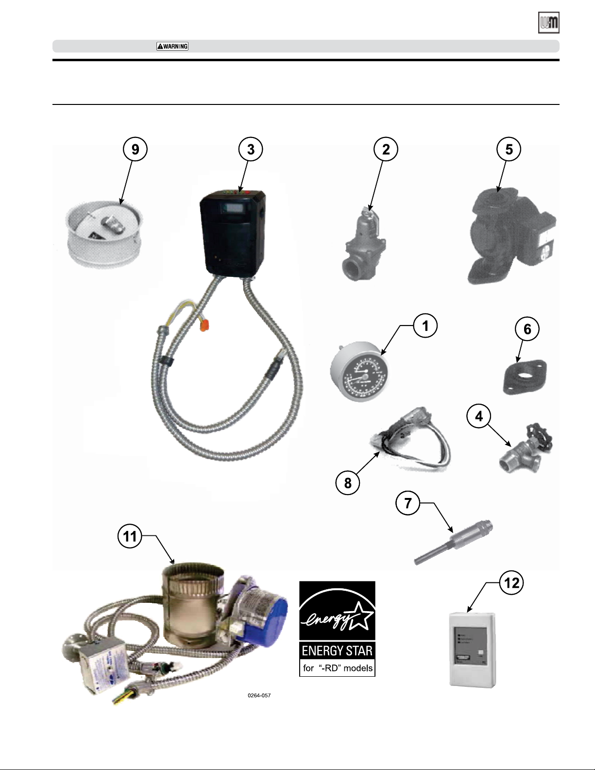
WGO
OIL-FIRED NATURAL DRAFT WATER BOILER — SERIES 4 — Boiler Manual
SERVICE TECHNICIAN ONLY — read and follow completely.
Replacement parts (continued)
Figure 32 WGO Trim part for Series 4
Part number 550-142-331/0421
37
Page 38
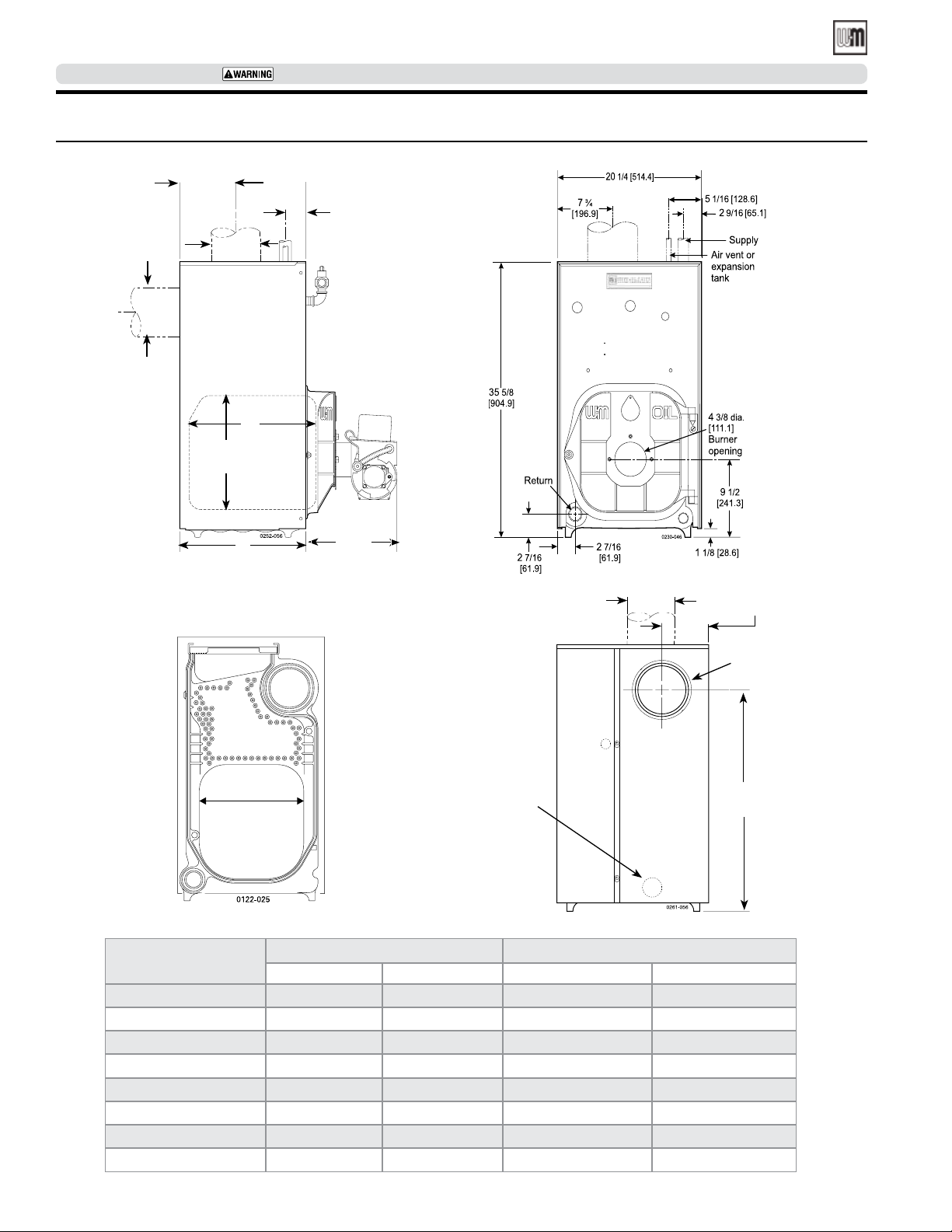
WGO
OIL-FIRED NATURAL DRAFT WATER BOILER — SERIES 4— Boiler Manual
SERVICE TECHNICIAN ONLY — read and follow completely.
Dimensions
Figure 33 WGO dimensions — inches (mm)
7 3/16
[182.6]
7 Dia
[177.8]
7 Dia
[177.8]
B
15 1/2
[393.7]
2 5/8
[66.7]
L
Left side
14 1/8 [358.8]
BOILER
Size
14
Approx.
Front
7 Dia.
[177.8]
Alternate
return
(“A”
boilers
only)
BackIntermediate
B L
Inches mm Inches mm
WGO-2 10 1/2 266.7 13 3/4 349.2
WGO-3 13 1/2 342.9 16 7/8 428.7
WGO-4 13 5/8 345.9 16 7/8 428.7
WGO-5 16 7/8 428.7 20 508.0
WGO-6 20 508 23 1/8 587.2
WGO-7 23 1/8 587.2 26 1/4 666.7
WGO-8 26 1/4 666.7 29 3/8 746.2
WGO-9 29 3/8 746.2 32 1/2 825.5
6 1/4
[158.8]
For 7
dia.
[177.8]
Vent
pipe
29 9/16
[750.9]
38
Part number 550-142-331/0421
Page 39
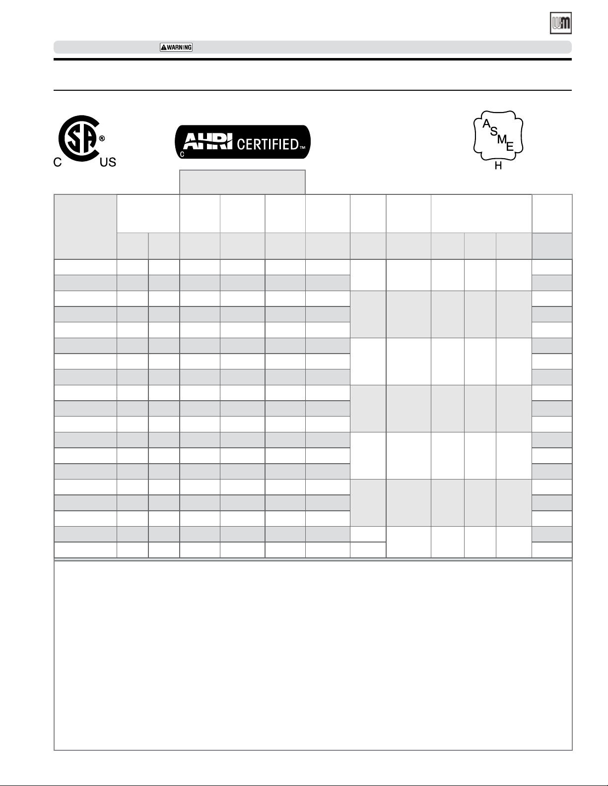
WGO
OIL-FIRED NATURAL DRAFT WATER BOILER — SERIES 4 — Boiler Manual
SERVICE TECHNICIAN ONLY — read and follow completely.
Ratings
Table 8 WGO Series 4 oil-red water boiler ratings
AHRI Certified Ratings
DOE
®
Burner Input
Boiler
Model
(9)
WGO-2 0.70 98 86 (4) 86.4 75 .010
WGO-2RD 0.70 98 86 (4) 87.0 75 .010
WGO-3R 0.80 112 98 (4) 86.2 85 .020
WGO-3RD 0.80 11 2 98 (4) 87.0 85 .010
WGO-3D 0.95 133 115 (4) 86.0 100 .020
WGO-4R 1.00 140 122 (4) 86.2 106 .010
WGO-4RD 1.00 140 123 (4) 87.0 107 .010
WGO-4D 1.20 168 146 (4) 86.0 127 .010
WGO-5R 1.20 168 147 (4) 86.1 128 .015
WGO-5RD 1.20 168 148 (4) 87 129 .015
WGO-5D 1.45 203 176 (10) 86.0 153 .015
WGO-6R 1.40 196 171 (4) 86.1 149 .015
WGO-6RD 1.40 196 173 (4) 87.0 150 .015
WGO-6D 1.75 245 213 (10) 86.0 185 .015
WGO-7R 1.60 224 196 (4) 86.0 170 .015
WGO-7RD 1.60 224 197 (4) 87.0 171 .015
WGO-7D 2.00 280 244 (10) 86.0 212 .015
WGO-8 2.30 322 266 (6)(4) - 231 0.025 23.3
WGO-9 2.55 357 295 (6)(4) - 257 0.030 25.8
GPH
(3)
MBH
Heating
Capacity
MBH
(3)
Seasonal
Efciency
AFUE % MBH
(2)
Net
Rating
(water)
(2) (5)
Draft
Loss
Thru
boiler
In W.C.
(8)
Boiler
Water
Content
Gallons Inches
Flue
Outlet
Diameter
(7)
11.0 7 8 x 8 6 15
14.9 7 8 x 8 6 15
13.4 7 8 x 8 6 15
15.9 7 8 x 8 7 15
18.4 7 8 x 8 7 15
20.8 7 8 x 8 8 15
7 8 x 12 8 20
Rect.
Inches
Minimum
Chimney
Round
Inches
Height
Feet
OVD
Damper
Required
Yes/No
No
Yes
No
Yes
Yes
No
Yes
Yes
No
Yes
Yes
No
Yes
Yes
No
Yes
Yes
No
No
(1) WGO boiler designed with convertible vertical and horizontal ue outlet.
(2) MBH refers to thousands of Btu per hour.
(3) Based on 140,000 Btu/gal.
(4) Based on standard test procedures prescribed by the United States Department of Energy at combustion condition of 13.5% CO
and -0.02” W.C. dra overre.
(5) Net AHRI ratings are based on net installed radiation of sucient quantity for the requirements of the building and nothing
need be added for normal piping and pick-up. Water ratings are based on a piping and pick-up allowance of 1.15. An additional
allowance should be made for unusual piping and pick-up loads.
(6) AHRI gross output.
(7) See page16 for minimum breeching diameter.
(8) Listed dra losses are for factory-shipped settings.
(9) Boiler model suxes: “R” designates a reduced input version. No separate/additional damper kit required. “D” designates that the
separate High Input OVD Automatic Vent Damper P/N 381-800-515 is required. “RD” designates a reduced input version and and
the separate ES Vent damper is required (P/N 381-800-501 through 381-800-506).
(10) Based on standard test procedures prescribed by the United States Department of Energy at combustion of 13.0% CO
W.C. dra overre.
NOTE: A burner nozzle change may be required - refer to the burner instructions or boiler’s rating label for correct selection.
Part number 550-142-331/0421
and -0.02”
2
2
39
Page 40
WGO
OIL-FIRED NATURAL DRAFT WATER BOILER — SERIES 4 — Boiler Manual
Handling ceramic fiber and fiberglass materials
REMOVAL OF COMBUSTION CHAMBER
LINING OR BASE PANELS
The combustion chamber lining or base insu-
lation panels in this product contain ceramic
fiber materials
cinogenic, or possibly carcinogenic, to humans
Ceramic fibers can be converted to cristobalite
in very high temperature applications. The
International Agency for Research on Cancer
(IARC) has concluded, “Crystalline silica
inhaled in the form of quartz or cristobalite
from occupational sources is carcinogenic to
humans (Group 1).”:
that have been identified as car-
Precautionary measures
Avoid breathing fiberglass dust and contact with
skin or eyes.
• Use NIOSH certified dust respirator (N95).
This type of respirator is based on the
OSHA requirements for fiberglass wool at the
time this document was written. Other types
of respirators may be needed depending on
the job site conditions. Current NIOSH recommendations can be found on the NIOSH web
site at http://www.cdc.gov/niosh/homepage.
html. NIOSH approved respirators, manufacturers, and phone numbers are also listed on
this web site.
• Wear long-sleeved, loose fitting clothing, gloves,
and eye protection.
Apply enough water to the combustion chamber
lining or base insulation to prevent airborne dust.
Remove combustion chamber lining or base insula-
tion from the boiler and place it in a plastic bag for
disposal.
Wash potentially contaminated clothes separately
from other clothing. Rinse clothes washer thoroughly.
NIOSH stated First Aid
Eye: Irrigate immediately
Breathing: Fresh air
REMOVAL OF FIBERGLASS WOOL
or
INSTALLATION OF FIBERGLASS WOOL
OR BASE PANELS:
.
This product contains fiberglass jacket
insulation and ceramic fiber materials in
combustion chamber lining or base panels
in gas fired products. Airborne fibers from
these materials have been listed by the State
of California as a possible cause of cancer
through inhalation.
Precautionary measures
Avoid breathing fiberglass dust and contact with
skin or eyes.
• Use NIOSH certified dust respirator
(N95). This type of respirator is based
on the OSHA requirements for fiberglass
wool at the time this document was written. Other types of respirators may be
needed depending on the job site conditions. Current NIOSH recommendations
can be found on the NIOSH web site at
http://www.cdc.gov/niosh/homepage.html.
NIOSH approved respirators, manufacturers, and phone numbers are also listed on
this web site.
• Wear long-sleeved, loose fitting clothing,
gloves, and eye protection.
Operations such as sawing, blowing, tear out, and
spraying may generate airborne fiber concentration requiring additional protection.
Wash potentially contaminated clothes separately
from other clothing. Rinse clothes washer thoroughly.
NIOSH stated First Aid
Eye: Irrigate immediately
Breathing: Fresh air
Part number 550-142-331/0421
 Loading...