

Page 1
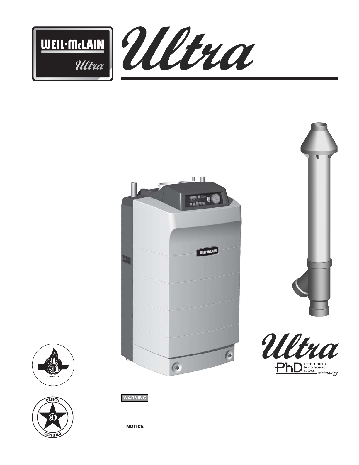
Gas-fired
water boiler
Vent Supplement
Concentric vent/air system:
Through-roof termination
(Weil-McLain kit part number 383-500-350)
[All piping (air and vent) must be PVC only]
with
This document must only be used by a qualified heating installer/service
technician. Read all instructions, including this Supplement and the Boiler
Manual, before installing. Perform steps in the order given. Failure to comply
could result in severe personal injury, death or substantial property damage.
Installation must comply with local requirements and with the National Fuel
Gas Code, ANSI Z223.1 for U.S. installations or CSA B149.1 or B149.2 for
Canadian installations.
Part No. 550-141-965/0703
Page 2
GAS-FIRED WATER BOILER — Vent Supplement
Contents
Please read before proceeding ........................................................ 2
Vent and air piping materials ............................................................ 3
Prepare boiler location ...................................................................... 4
Concentric termination location....................................................... 6
Assembling concentric vent/air kit .................................................. 8
Installing vent & air piping .............................................................. 10
Please read before proceeding
These instructions are for installation of vent and air piping for Weil-McLain Ultra boilers, using WeilMcLain concentric vent termination kit, part number 383-500-350. Do not apply these instructions or
the kit components to any other boiler or appliance. Failure to comply could result in personal injury
or death.
Installer
Read all instructions before installing.
Follow all instructions in proper order
to prevent personal injury or death.
• This document is intended only as a supplement
to the Ultra Boiler Manual. It’s purpose is for the
installation of vent and air piping for the boiler.
All Ultra boilers must be installed as direct vent. This requires piping
installation for both flue products (vent) and combustion air (air piping).
All vent and air piping must be installed, terminated and sealed as described
in this supplement. Failure to adhere to the guidelines in this supplement
can result in severe personal injury, death or substantial property damage.
User
• This document is for use only by your qualified
heating installer/service technician.
• Please refer to the User’s Information Manual for
your reference.
• Keep this supplement near the boiler for use by
your installer or technician.
Hazard definitions
The following defined terms are used throughout this manual to bring attention to the presence of hazards of
various risk levels or to important information concerning the life of the product.
Indicates presence of hazards that will cause severe personal injury, death or substantial property
damage.
Indicates presence of hazards that can cause severe personal injury, death or substantial property
damage.
Indicates presence of hazards that will or can cause minor personal injury or property damage.
Indicates special instructions on installation, operation or maintenance that are important but not
related to personal injury or property damage.
2
Part number 550-141-965/0703
Page 3
GAS-FIRED WATER BOILER — Vent Supplement
1
Vent and air piping materials
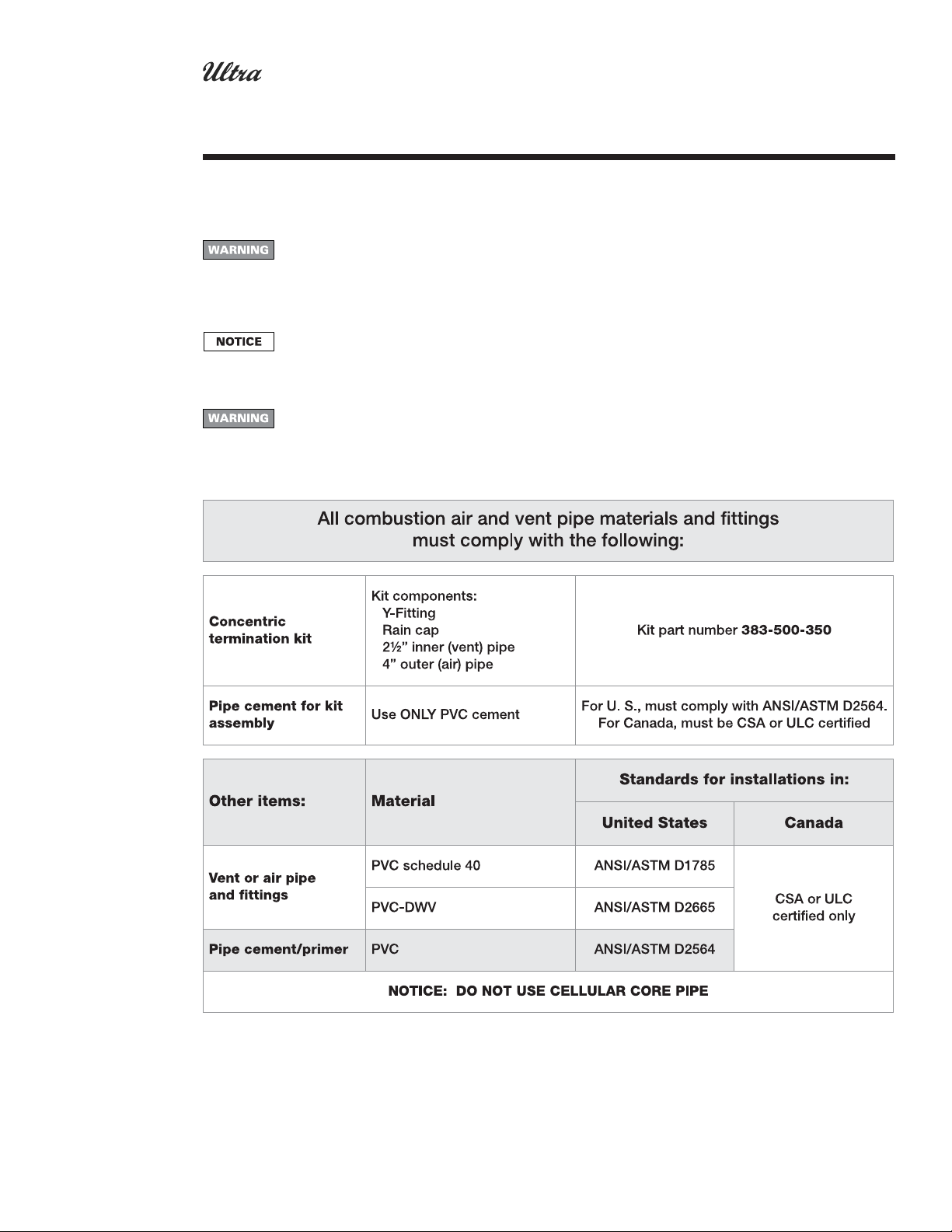
Use only the materials listed in the table below (PVC pipe and PVC cement only) for vent and air pipe
and fittings. Install the concentric vent termination kit as described in this supplement. Failure to
comply could result in severe personal injury, death or substantial property damage.
Installation must comply with local requirements and with the National Fuel Gas Code, ANSI Z223.1
for U.S. installations or CSA B149.1 or B149.2 for Canadian installations.
DO NOT attempt to modify kit components. DO NOT extend or cut the inner or outer PVC pipe
sections provided with the kit. Install the kit as supplied, without alteration. Failure to comply could
result in severe personal injury, death or substantial property damage.
Part number 550-141-965/0703
3
Page 4
GAS-FIRED WATER BOILER — Vent Supplement
2
Prepare boiler location
When removing a boiler from existing vent
Do not install the Ultra into a common vent with any other
appliance. This will cause flue gas spillage or appliance
malfunction, resulting in possible severe personal injury, death
or substantial property damage.
Failure to follow all instructions can result in flue gas spillage
and carbon monoxide emissions, causing severe personal injury
or death.
When removing existing boiler from existing common
vent system:
At the time of removal of an existing boiler, the following steps shall be
followed with each appliance remaining connected to the common venting
system placed in operation, while the other appliances remaining connected
to the common venting system are not in operation.
a. Seal any unused openings in the common venting system.
b. Visually inspect the venting system for proper size and horizontal pitch
and determine there is no blockage or restriction, leakage, corrosion or
other deficiencies which could cause an unsafe condition.
c. Test vent system — Insofar as is practical, close all building doors and
windows and all doors between the space in which the appliances
remaining connected to the common venting system are located and
other spaces of the building. Turn on clothes dryers and any appliance
not connected to the common venting system. Turn on any exhaust fans,
such as range hoods and bathroom exhausts, so they will operate at
maximum speed. Do not operate a summer exhaust fan. Close fireplace
dampers.
d. Place in operation the appliance being inspected. Follow the lighting
instructions. Adjust thermostat so appliance will operate continuously.
e. Test for spillage at draft hood relief opening after 5 minutes of main
burner operation. Use the flame of a match or candle, or smoke from a
cigarette, cigar, or pipe.
f. After it has been determined that each appliance remaining connected to
the common venting system properly vents when tested as outlined herein,
return doors, windows, exhaust fans, fireplace dampers, and any other
gas-burning appliance to their previous conditions of use.
Any improper operation of common venting system should be corrected so
the installation conforms with the National Fuel Gas Code, ANSI Z223.1 —
latest edition. Correct by resizing to approach the minimum size as determined
using the appropriate tables in Part 11 of that code. Canadian installations
must comply with B149.1 or B149.2 Installation Code.
Vent and air piping
Vent and air system
Installation must comply with local
requirements and with the National Fuel
Gas Code, ANSI Z223.1 for U.S.
installations or CSA B149.1 or B149.2 for
Canadian installations.
The Ultra boiler requires a special vent system, designed
for pressurized venting. Ultra boilers are rated ANSI
Z21.13 Category IV (pressurized vent, likely to
condense in the vent).
You must also install air piping from outside to the
boiler air intake adapter. The resultant installation is
categorized as direct vent (sealed combustion).
You may use any of the vent/air piping methods
covered in this supplement or other Ultra venting
supplements. Do not attempt to install the Ultra boiler
using any other means. This supplement covers only
vertical vent/air termination, using the Weil-McLain
concentric termination assembly.
DO NOT mix components from different
systems. The vent system could fail, causing
leakage of flue products into the living space.
Use only PVC pipe and fittings for all vent
and air piping and fittings, with primer and
cement specifically designed for the PVC.
Concentric termination installation
The Ultra boiler concentric vent system can only be
terminated vertically (not intended for sidewall
termination). The maximum vent/air piping length
depends on boiler size. Refer to the information in this
supplement to determine acceptable vent and air piping
length.
Combustion air for the Ultra boiler must be ducted
directly to the boiler from outside (direct vent
installation).
Follow all instructions in this document and the Ultra
Boiler Manual to install vent and air piping.
4
Part number 550-141-965/0703
Page 5
GAS-FIRED WATER BOILER — Vent Supplement
2
Prepare boiler location
Air contamination
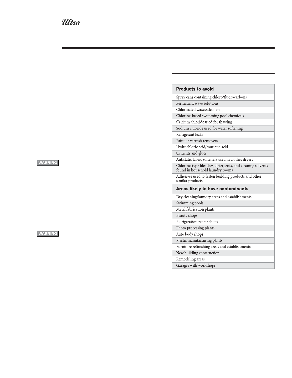
Pool and laundry products and common household
and hobby products often contain fluorine or chlorine
compounds. When these chemicals pass through the
boiler, they can form strong acids. The acid can eat
through the boiler wall, causing serious damage and
presenting a possible threat of flue gas spillage or boiler
water leakage into the building.
Please read the information given in Table 1, listing
contaminants and areas likely to contain them. If
contaminating chemicals will be present near the
location of the boiler combustion air inlet, have your
installer pipe the boiler combustion air and vent to
another location, per the Boiler Manual and Vent
Supplement.
If the boiler combustion air inlet is located in any area
likely to cause air contamination, or if products which
would contaminate the air cannot be removed, you
must have the combustion air and vent repiped and
terminated to another location. Contaminated
combustion air will damage the boiler heat exchanger,
resulting in possible severe personal injury, death or
substantial property damage.
Table 1 Corrosive contaminants
(continued)
Do not operate an Ultra boiler if the boiler combustion
air inlet is located in a laundry room or pool facility,
for example. These areas will always contain hazardous
contaminants.
To prevent the potential of severe personal injury or
death, check for areas and products listed in Table 1
before installing the boiler or air inlet piping.
If contaminants are found, you MUST:
• Remove products permanently. — OR —
• Relocate air inlet and vent terminations to other areas.
Part number 550-141-965/0703
5
Page 6
GAS-FIRED WATER BOILER — Vent Supplement
Concentric termination location3
Follow instructions below when determining vent location
to avoid possibility of severe personal injury, death or
substantial property damage.
Installation must comply with local requirements and
with the National Fuel Gas Code, ANSI Z223.1 for U.S.
installations or CSA B149.1 or B149.2 for Canadian
installations.
Determine location
Locate the concentric vent/air termination using the
following guidelines:
1. The total length of piping for vent or air must not
exceed the limits given in Table 2, page 11.
2. The concentric vent/air assembly must terminate as
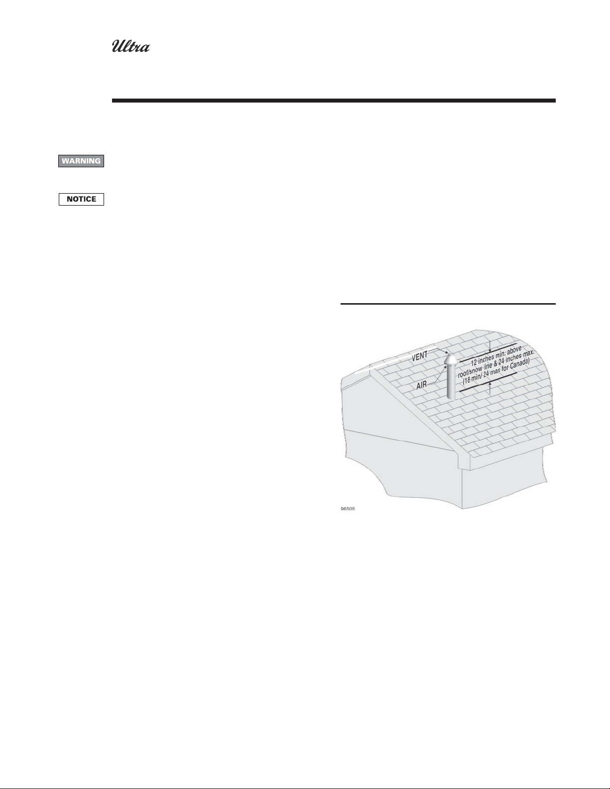
shown in Figure 1.
3. The vent and air piping connected to the termination
assembly must comply with the instructions in this
supplement.
4. You must consider the surroundings when
terminating the vent and air:
a. Position the termination where vent vapors will not
damage nearby shrubs, plants or air conditioning
equipment or be objectionable.
b. The flue products will form a noticeable plume
as they condense in cold air. Avoid areas where
the plume could obstruct window views.
c. Prevailing winds could cause freezing of condensate
and water/ice buildup where flue products impinge
on building surfaces or plants.
d. Avoid possibility of accidental contact of flue products
with people or pets.
e. Do not locate the termination where wind eddies
could affect performance or cause recirculation, such
as inside building corners, near adjacent buildings or
surfaces, window wells, stairwells, alcoves, courtyards
or other recessed areas.
f. Locate or guard vent outlet to prevent condensate
damage to exterior finishes.
5. Maintain clearances to termination as given below:
a. Vent outlet must be located:
• At least 6 feet from adjacent walls.
• No closer than 5 feet below roof overhang.
• At least 7 feet above any public walkway.
• At lease 3 feet above any forced air intake within
10 feet.
• No closer than 12 inches below or horizontally from
any door or window or any other gravity air inlet.
b. Air inlet must terminate at least 12" above the roof or
snow line as shown in Figure 1. (For Canada, the
minimum is 18 inches.)
c. Do not terminate closer to 4 feet horizontally from
any electric meter, gas meter, regulator, relief valve or
other equipment. Never terminate above or below
any of these within 4 feet horizontally.
6. Locate termination so it is not likely to be damaged
by foreign objects, such as stones or balls, or subject
to buildup of leaves or sediment.
7. Do not connect any other appliance to the vent pipe
or multiple boilers to a common vent pipe.
Figure 1 Concentric termination placement
Prepare roof penetration
1. Roof penetration hole:
a. Cut a 5-inch diameter hole to clear the 4½"
termination outside diameter.
b. Insert a galvanized metal thimble in the vent pipe
hole.
2. Follow all local codes for isolation of vent pipe when
passing through floors, ceilings and roofs.
3. Provide flashing and sealing boots sized for the
concentric termination outside diameter, 4½ inches.
4. Mount the termination as shown in Figure 2, with
no changes to any termination component.
6
Part number 550-141-965/0703
Page 7
GAS-FIRED WATER BOILER — Vent Supplement
3
Concentric termination location
Vent termination support
1. Do not alter any component of the concentric vent/
air termination assembly. Assemble and install all
components as supplied.
2. Support the concentric vent/air termination at the
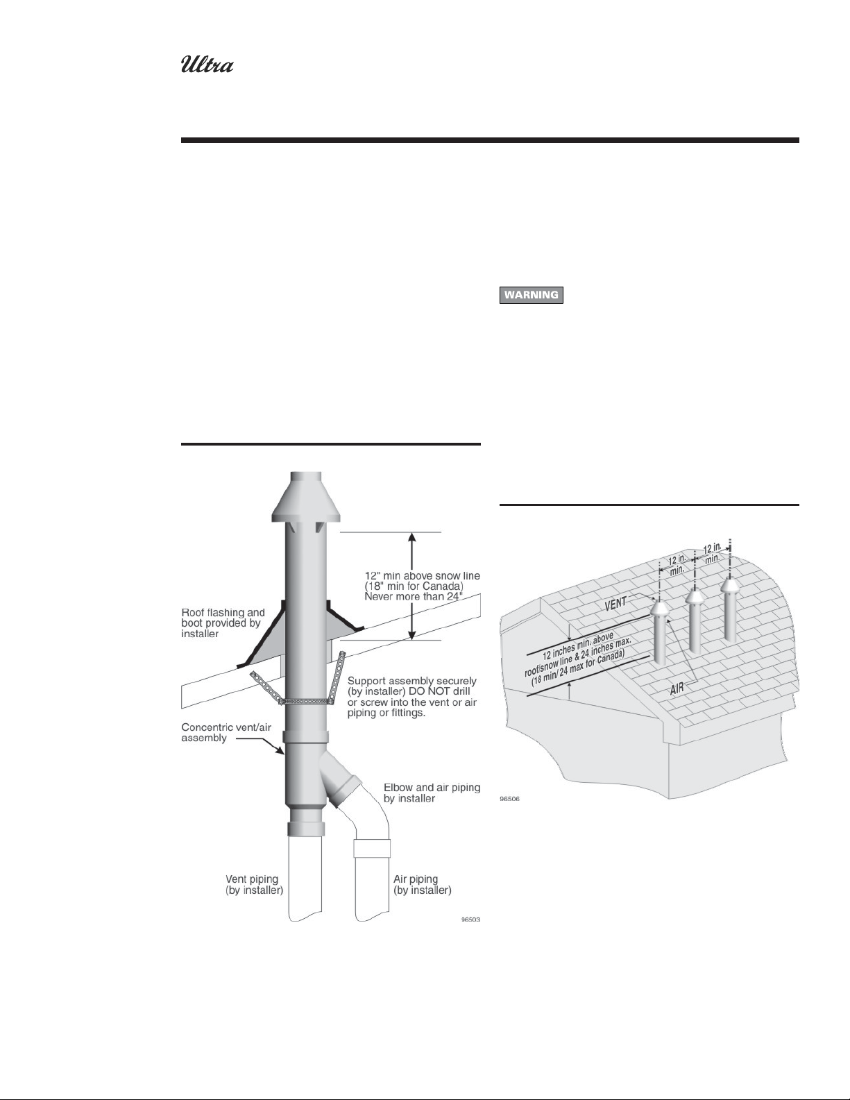
roof penetration as shown in Figure 2.
• The supports/bracing used must support the
termination assembly to prevent vertical slippage
or sideways movement.
• The clamps used on the outside of the termination
pipe must not cut into the pipe or contain sharp
edges that could cause a crack to form.
Figure 2 Termination supports
Multiple vent/air terminations
1. When terminating multiple Ultra boilers, install the
concentric vent/air termination assemblies as
described in this supplement.
All vent outlets must terminate at the same
height to avoid possibility of severe
personal injury, death or substantial
property damage.
2. Place roof penetrations to obtain minimum of 12
inches between centers of adjacent vent pipe of another
boiler for U. S. installations (see Figure 3). For
Canadian installations, provide clearances required
by CSA B149.1 or B149.2 Installation Code.
3. The air inlet of an Ultra boiler is part of a direct vent
connection. It is not classified as a forced air intake
with regard to spacing from adjacent boiler vents.
Figure 3 Multiple terminations
(continued)
Part number 550-141-965/0703
7
Page 8
GAS-FIRED WATER BOILER — Vent Supplement
Assembling concentric vent/air kit4
Assembling the termination
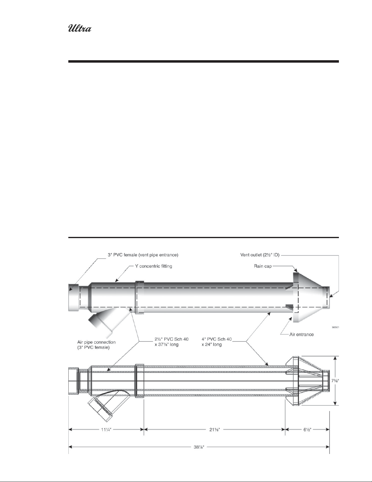
1. See Figure 4 for the dimensions and details of the
termination assembly.
2. Prepare the bird screen.
a. Locate the bird screen provided with the boiler.
b. Cut the bird screen to fit the outside diameter of
the 2½-inch PVC inner pipe supplied with the
termination kit (inner pipe O.D. is 27/8 inches).
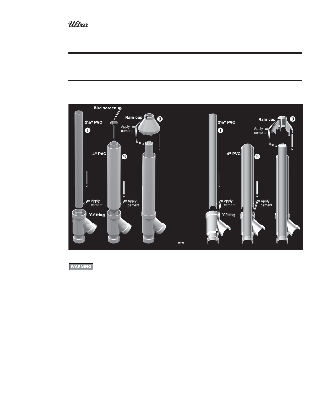
3. Partially assemble the vent termination kit in the
sequence shown in Figure 5.
• DO NOT install the rain cap and bird screen until
the assembly has been inserted through the roof
and all supports have been installed.
• Use the following procedures to prepare
termination components and cement together.
4. Deburr inside and outside of pipe ends.
5. Chamfer outside of each pipe end to ensure even
cement distribution when joining.
Figure 4 Concentric vent termination assembly (DO NOT alter vent components)
6. Clean all pipe ends and fittings. Dry thoroughly.
7. Dry assemble entire vent or air piping to ensure
proper fit before assembling any joint.
8. For each joint:
a. Handle fittings and pipes carefully to prevent
contamination of surfaces.
b. Apply primer liberally to both joint surfaces — pipe
end and fitting socket.
c. While primer is still damp, lightly apply approved
cement to both surfaces in a uniform coating.
d. Apply a second coat to both surfaces. Avoid using too
much cement on sockets to prevent cement buildup
inside.
e. With cement still wet, insert pipe into fitting, twisting
¼ turn. Make sure pipe is fully inserted.
f. Wipe excess cement from joint. Check joint to be
sure a smooth bead of cement shows around the entire
joint.
8
Part number 550-141-965/0703
Page 9
GAS-FIRED WATER BOILER — Vent Supplement
4
Assembling concentric vent/air kit
Figure 5 Concentric vent termination assembly DO NOT alter vent components. DO NOT attach
the rain cap until the termination has been inserted through the roof and all supports have
been installed.
(continued)
Part number 550-141-965/0703
Do not cut or alter any concentric vent termination component. And ensure all joints are secure and
completely sealed. Failure to comply could result in severe personal injury, death or substantial property
damage.
9
Page 10
GAS-FIRED WATER BOILER — Vent Supplement
Installing vent & air piping5
Installation must comply with local requirements and
with the National Fuel Gas Code, ANSI Z223.1 for U.S.
installations or CSA B149.1 or B149.2 for Canadian
installations.
Mount concentric termination
1. Before beginning vent and air piping from boiler,
mount and secure the concentric termination as
shown in Figure 2, page 7.
2. When inserting the partially-assembled termination
kit through the roof penetration, wrap plastic or other
protection over the end of the exposed assembly to
prevent debris from entering the pipes.
3. After the assembly has been positioned in the roof
opening and all supports have been attached, install
the bird screen and rain cap as follows:
• Place the bird screen on the end of the inner pipe
as in Figure 5, page 9.
• Cement the rain cap in place as shown.
Inserting/securing vent or air
pipe into boiler adapters
1. Clean and chamfer insertion end of pipe. Deburr
inside of insertion end. Clean and deburr inside
and outside of other end of pipe.
The pipe end must be smooth and
chamfered to prevent possible damage to
sealing gasket in vent or air pipe adapter.
Failure to comply could result in leakage,
causing possible severe personal injury or
death.
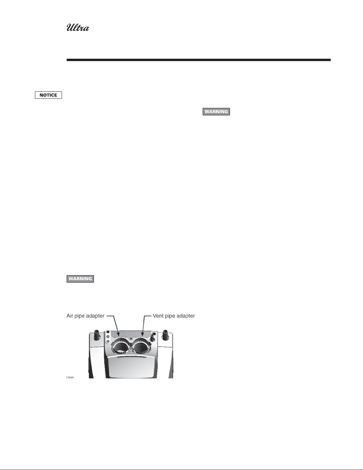
2. Inspect vent or air adapter (above) — verify no
obstructions or foreign objects inside.
3. Loosen clamp screw.
4. Measure 3½ inches from end of pipe and make a
mark with felt-tip pen.
5. Loosen adapter clamp screw.
6. Apply small amount of silicon grease to end of pipe
to ease insertion.
7. Insert pipe into adapter.
8. Slide pipe down until the 3½-inch mark is reached.
Do not apply excessive force or bend the
adapter or flue/air pipe when inserting.
The adapter or seal could be damaged.
9. Secure vent or air pipe by tightening the adapter clamp
securely. Do not overtighten. The seal is accomplished
with the internal gasket. The clamp is only to hold
the pipe in place.
Installing vent or air piping
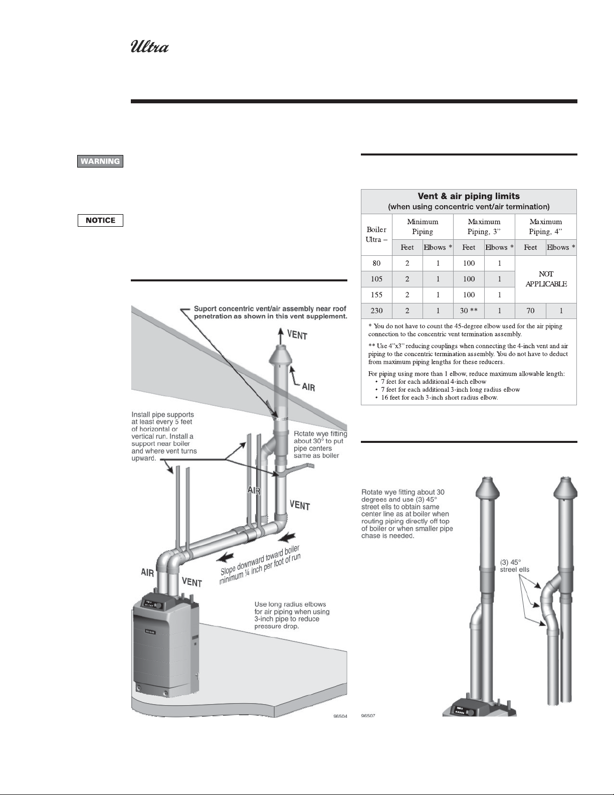
For reference in following see Figure 9, page 11.
1. Work from the boiler to the concentric vent/air
termination. Do not exceed the lengths given in
Table 2, page 11, for either the air or vent piping.
a. Note that the Ultra-230 may be installed with either
3-inch or 4-inch vent and air piping. Table 2 provides
shorter allowable piping lengths when using 3-inch
piping. Reduce the vent and air pipe size at the
connection to the termination fitting using reducing
couplings.
2. Cut pipe to required lengths.
3. Deburr inside and outside of pipe ends.
4. Chamfer outside of each pipe end to ensure even
cement distribution when joining.
5. Clean all pipe ends and fittings. Dry thoroughly.
6. Dry assemble entire vent or air piping to ensure
proper fit before assembling any joint.
7. For each joint:
a. Handle fittings and pipes carefully to prevent
contamination of surfaces.
b. Apply primer liberally to both joint surfaces — pipe
end and fitting socket.
c. While primer is still damp, lightly apply approved
cement to both surfaces in a uniform coating.
d. Apply a second coat to both surfaces. Avoid using too
much cement on sockets to prevent cement buildup
inside.
e. With cement still wet, insert pipe into fitting, twisting
¼ turn. Make sure pipe is fully inserted.
f. Wipe excess cement from joint. Check joint to be
sure a smooth bead of cement shows around the entire
joint.
8. Install perforated metal pipe supports or equivalent
as shown in Figure 9, page 11.
9. Slope vent and air piping continuously toward boiler,
with at least ¼ inch drop per foot of run. Do not
allow sags at any point.
10. Maintain minimum clearance of 0.2 inch between
vent pipe and any combustible wall or material. Seal
wall or floor penetration openings following local
code requirements.
10
Part number 550-141-965/0703
Page 11
GAS-FIRED WATER BOILER — Vent Supplement
5
Installing vent & air piping
Do not insulate vent piping. Exception: Where vent pipes
pass through unheated spaces, such as crawl spaces or
unheated garages, apply ½ inch fiberglass insulation to
the portion of the vent pipe in the unheated space only.
When a large number of elbows is needed with 3-inch
piping, use long radius elbows to reduce pressure drop.
This allows a longer run of piping. See Table 2 notes for
details.
Figure 9 Vent/air piping installation
Table 2 Min/max lengths of either air piping
or vent piping
(continued)
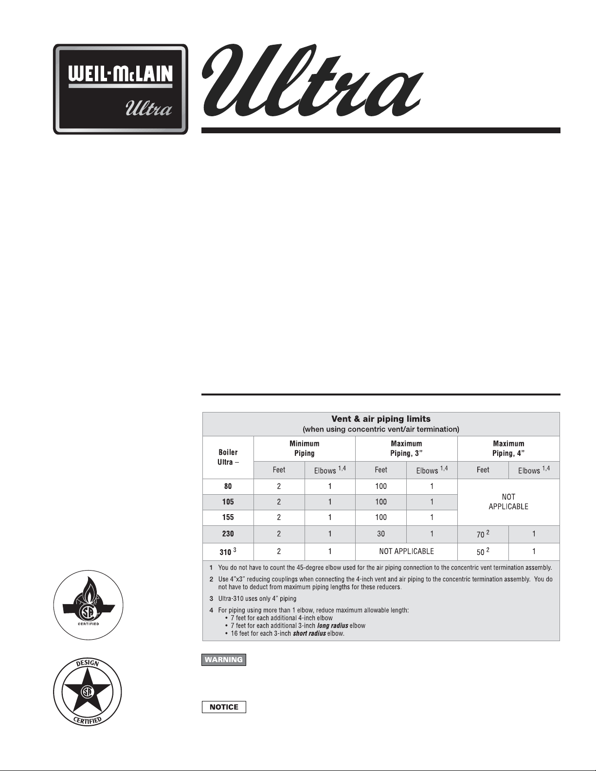
Table replaced by addendum see next page
Figure 9a Alternate piping arrangement using
(3) 45° street ells for closer pipe
centers
Part number 550-141-965/0703
11
Page 12
Gas-fired
water boiler
Vent Supplement
Concentric vent/air system:
Through-roof termination
(Weil-McLain kit part number 383-500-350)
[All piping (air and vent) must be PVC only]
Addendum
This Addendum replaces table 2, page 11 in the “Ultra Vent Supplement”
(Part number 550-141-965/0703).
T able 2 Min/max lengths of either air piping or vent piping
This document must only be used by a qualified heating installer/service
technician. Read all instructions, including this Supplement and the Boiler
Manual, before installing. Perform steps in the order given. Failure to comply
could result in severe personal injury, death or substantial property damage.
Installation must comply with local requirements and with the National Fuel
Gas Code, ANSI Z223.1 for U.S. installations or CSA B149.1 or B149.2 for
Canadian installations.
Part No. 550-141-967/1003
Page 13

GAS-FIRED WATER BOILER — Vent Supplement
12
Part Number 550-141-965/0703
 Loading...