

Page 1
®
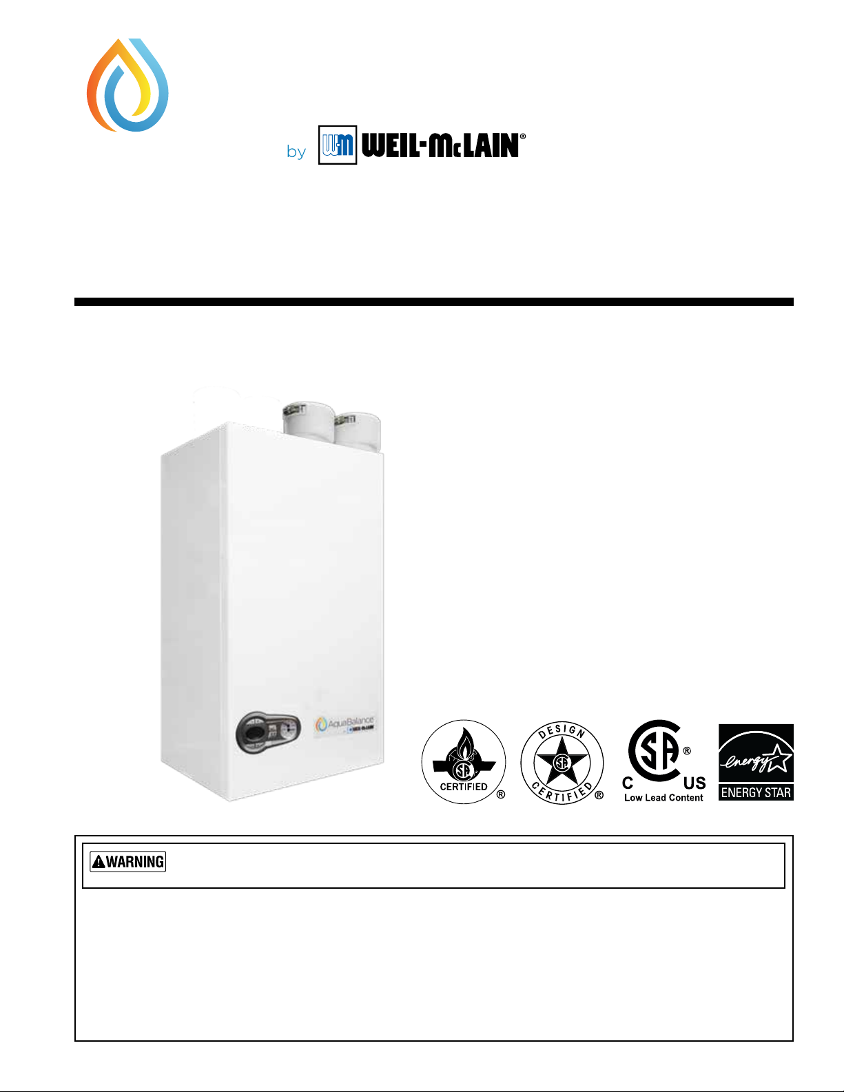
Aqua Balance
80/120/155
Series 2
Wall Mount Gas-Fired
Condensing Boilers – Combi and Heating Only Models
User’s Information Manual
*
If the information in this manual is not followed exactly, a re or explosion may result, causing
property damage, personal injury or loss of life.
Do not store or use gasoline or other ammable vapors and liquids in the vicinity of this or any other appliance.
— WHAT TO DO IF YOU SMELL GAS —
• Do not try to light any appliance.
• Do not touch any electrical switch; do not use any telephone in your building.
• Immediately call your gas supplier from a neighbor’s telephone. Follow the gas supplier’s instructions.
• If you cannot reach your gas supplier, call the re department.
Installation & service must be performed by a qualied installer, service technician or the gas supplier.
Part number 550-100-326/0122
Page 2
AquaBalance
®
series
2
wall mount gas-fired water boiler – user information manual
Please read this page rst
To . . . Read and use . . . Page
Learn
precautions
Locate boiler
components
Guidelines
Prevent air
contamination
Maintain
boiler
Start — or —
Shutdown
boiler
Understand
control
display
See Hazard Denitions, below
See illustration at right
See “Read before proceeding”
Laundry room or pool — make sure
boiler air is piped to boiler per manual.
Read list of air contaminants you must
avoid. Have boiler air re-piped to
another location if you can’t avoid.
Set up a plan for maintaining the
boiler using the schedule included in
this manual.
Schedule an annual start-up by a
qualied service technician before
every heating season.
Follow the Operating instruction
sheet details to start or shutdown your
boiler.
This page shows display screen
modes and menu access information.
2
2
3
4
5
10
11
Boiler Components
Pressure/temperature gauge
Control display
and buttons
Boiler
Return
(inlet)
Hazard denitions
e following dened terms are used throughout this manual to
bring attention to the presence of hazards of various risk levels or
to important information concerning the life of the product.
Indicates presence of hazards that will cause severe
personal injury, death or substantial property damage.
Indicates presence of hazards that can cause severe
personal injury, death or substantial property damage.
Indicates presence of hazards that will or can cause
minor personal injury or property damage.
Indicates special instructions on installation, operation
or maintenance that are important but not related to
personal injury or property damage.
Have this boiler serviced/inspected by
a qualied service technician, at least
annually.
Failure to comply with the above could result
in severe personal injury, death or substantial
property damage.
When calling or writing about the boiler—
Please have the boiler model number from the
boiler rating label and the CP number from the
boiler cabinet.
Boiler Supply
(outlet)
Relief valve
MANUAL GAS VALVE
Condensate drain line installed
here. (Drain line must be installed
by a qualied technician per the
boiler manual).
Relief valve drain line (must be run
to a safe drainage location — must
be installed by a qualied technician
per the boiler manual).
2
Part number 550-100-326/0122
Page 3
AquaBalance
®
series
2
wall mount gas-fired water boiler – user information manual
STOP!! — Read before proceeding
If any part of a boiler, burner or its controls has
been sprayed with or submerged under water,
either partially or fully, DO NOT attempt to operate the boiler until the boiler has been either
replaced or completely repaired, inspected, and
you are sure that the boiler and all components
are in good condition and fully reliable.
Otherwise, by operating this boiler, you will cause
a re or explosion hazard, and an electrical shock
hazard, leading to serious injury, death, or substantial property damage. See the instructions at right.
Failure to adhere to the guidelines on this page can result in severe personal
injury, death or substantial property damage.
Boiler service and maintenance —
• To avoid electric shock, disconnect electrical supply
before performing maintenance.
• To avoid severe burns, allow boiler to cool before per-
forming maintenance.
• You must maintain the boiler as outlined in the manual
and have the boiler started up and serviced at least
annually by a qualied service technician to ensure
boiler/system reliability.
Should overheating occur or gas supply fail to
shut off, DO NOT turn o or disconnect electrical
supply to circulator. Instead, shut o the gas supply at
a location external to the appliance.
Boiler operation —
y Do not block ow of combustion or ventilation air to boiler.
is boiler is equipped with a control which will automatically
shut down the boiler should air or vent be blocked. If vent or
air blockage is easily accessible and removable, remove it. e
boiler should attempt to restart within an hour. If blockage is
not obvious or cannot be removed, have the boiler and system
checked by a qualied service technician.
Combustion air —
y DO NOT obstruct the combustion air intake or
expose the air intake to corrosive chemicals (see
next page).
Carbon monoxide detector —
y A carbon monoxide detector that is wired on the same
electrical circuit as the boiler is strongly recommended.
Boiler water —
y Do not use petroleum-based cleaning or sealing compounds
in boiler system. Gaskets and seals in the system may be damaged. is can result in substantial property damage.
y Leaks in boiler or piping must be repaired at once
to prevent make-up water. Use this boiler ONLY in
a closed-loop system. Continual fresh make-up water
will reduce boiler life. Mineral buildup in heat exchangers
reduces heat transfer, overheats the materials, and causes
failure. Addition of oxygen carried in by make-up water can
cause internal corrosion.
y Do not add cold water to hot boiler. ermal shock can
cause heat exchanger to crack.
Saltwater Damage — e exposure of boiler components to saltwater
can have both immediate and long-term eects. While the immediate effects of saltwater damage are similar to those of freshwater (shorting out
of electrical components, washing out of critical lubricants, etc.), the salt
and other contaminants le behind can lead to longer term issues aer
the water is gone due to the conductive and corrosive nature of the salt
residue. erefore, Weil-McLain equipment contaminated with saltwater
or polluted water will no longer be covered under warranty and should
be replaced.
Electrical Damage
into contact with water, or was suspected to have come into contact
with water, replace the boiler with a new Weil-McLain boiler.
— If any electrical component or wiring came
Water chemistry
Water quality must be maintained as described in boiler
manual.
Water pH between 7.0 and 8.5
1. Maintain boiler water pH between 7.0 and 8.5. Check
with litmus paper or have chemically analyzed by water
treatment company.
2. If pH diers from above, consult local water treatment
company for treatment needed.
Hardness less than 7 grains
1. Consult local water treatment companies for unusually
hard water areas (above 7 grains hardness).
Chloride concentration must be
LESS THAN 50 ppm
1. Filling with chlorinated fresh water should be acceptable
since drinking water chloride levels are typically less than
5 ppm.
2. Do not use the boiler to directly heat swimming pool or
spa water.
3. Do not ll boiler or operate with water containing chloride
in excess of 50ppm.
Verify that the water chemistry meets the limita-
tions and requirements of all other equipment in
the system.
Freeze protection uids —
y NEVER use automotive or standard glycol antifreeze. Use
only freeze-protection uids made for hydronic systems.
Follow all guidelines given by the antifreeze manufacturer.
oroughly clean and ush any replacement boiler system
that has used glycol before installing the new boiler.
Antifreeze
1. Use only antifreeze listed by Weil-McLain as suitable for
use with boilers.
Frozen Water Damage Hazard
Residences or buildings that are unattended in severely cold
weather, boiler system components failures, power outages, or
other electrical system failures could result in frozen plumbing
and water damage in a matter of hours. For your protection, take
preventative actions such as having a security system installed
that operates during power outages, senses low temperature, and
initiates an eective action. Consult with your boiler contractor
or a home security agency.
Part number 550-100-326/0122
3
Page 4
AquaBalance
®
series
2
wall mount gas-fired water boiler – user information manual
Prevent combustion air contamination
Air contamination
Common household and hobby products oen contain
uorine or chlorine compounds. When these chemicals
pass through the boiler, they can form strong acids in
the vent system or boiler. e acid can eat through the
vent or boiler wall, causing serious damage and presenting a possible threat of ue gas spillage into the building.
Please read the information on this page.
If the boiler combustion air inlet is
located in any area likely to cause
contamination, or if products which
would contaminate the air cannot
be removed, you must have the
combustion air and vent re-piped
and terminated to another location
Contaminated combustion air will dam-
age the boiler, resulting in possible severe
personal injury, death or substantial
property damage.
Combustion air contamination:
Ensure that the combustion air will not contain any of
the contaminants in Figure 1
Combustion air supply openings or intake terminations
must NOT be near a swimming pool, for example.
Avoid areas subject to exhaust fumes from laundry facili-
ties. ese areas will always contain contaminants.
Figure 1
Products to avoid
.
Corrosive contaminants and sources
Spray cans containing chloro/uorocarbons
Permanent wave solutions
Chlorinated waxes/cleaners
Chlorine-based swimming pool chemicals
Calcium chloride used for thawing
Sodium chloride used for water softening
Refrigerant leaks
.
Do not operate the boiler if its combustion air inlet is located in a laundry room or pool facility, for example.
ese areas will always contain hazardous
contaminants.
Paint or varnish removers
Hydrochloric acid/muriatic acid
Cements and glues
Antistatic fabric softeners used in clothes dryers
Chlorine-type bleaches, detergents, and cleaning solvents found in
household laundry rooms
Adhesives used to fasten building products and other similar products
Excessive dust and dirt
Areas likely to have contaminants
Dry cleaning/laundry areas and establishments
Swimming pools
Metal fabrication plants
Beauty shops
Refrigeration repair shops
Photo processing plants
Auto body shops
Plastic manufacturing plants
Furniture renishing areas and establishments
New building construction
4
Part number 550-100-326/0122
Page 5
AquaBalance
®
series
2
wall mount gas-fired water boiler – user information manual
Annual startup and general maintenance
Figure 2 Service and maintenance schedules
OWNER MAINTENANCE (see the following pages for instructions)
Contact your boiler service technician to inspect, service and start
BEGINNING OF SEASON
DAILY
up your boiler. You must have an annual start-up performed by
a qualied service technician to ensure reliable operation of the
boiler and system.
• Check boiler area.
• Check air openings.
• Check pressure/temperature gauge.
MONTHLY
EVERY 6 MONTHS
• Verify boiler jacket door is securely closed.
• Check vent piping.
• Check air piping.
• Check relief valve.
• Check condensate drain system.
• Check automatic air vents (if used).
• Check display date and time.
• Check boiler piping (gas and water).
• Operate relief valve.
Follow the service and maintenance procedures given throughout this manual and in component literature
shipped with the boiler. Failure to perform the service and maintenance could result in damage to the boiler or
system. Failure to follow the directions in this manual and component literature could result in severe personal
injury, death or substantial property damage.
Part number 550-100-326/0122
5
Page 6

AquaBalance
®
series
2
wall mount gas-fired water boiler – user information manual
Annual startup and general maintenance
FIRST-YEAR SPECIAL INSPECTION
1. No later than 12 months aer the boiler is installed, perform a
rst-year inspection of the boiler. is should include the following in
addition to routine annual start-up procedures
a. e integrity of the ue system and the ue seals.
b. e integrity of the boiler combustion circuit and the relevant seals.
c. e operational (working) gas inlet pressure at maximum rate, as
described in the boiler manual.
d. e gas rate, as described in the boiler manual.
e. e combustion performance, as described in the boiler manual
for combustion check.
f. Competence to carry out the check of combustion performance.
g. e person carrying out a combustion measurement should have
been assessed as competent in the use of a ue gas analyzer and the
interpretation of the results.
Periodical check
h. To keep the unit working properly over time, it is necessary to
have qualied personnel make an annual check that includes the
following tests:
i. e control and safety devices (gas valve, ow meter, thermostats,
etc.) must function correctly.
j. e ue pipes must be fully intact, secure and clear.
k. e airtight chamber must be sealed.
l. e air-ue terminal and ducts must be free of obstructions and
leaks.
m. e condensate evacuation system must be ecient with no leakage
or obstructions and drain condensate without backing up.
n. e burner and exchanger must be clean and free of scale. When
cleaning, do not use chemical products or wire brushes.
o. e electrode must be free of scale and properly positioned
p. e gas and water systems must be leak free.
q. e water pressure in the heating system must be about 18 pounds;
ll the boiler to that pressure or the system design pressure.
r. e circulation pump must not be blocked.
s. e expansion tank must be lled.
t. e gas ow and pressure must correspond to that given in the
respective tables.
2. Determine any follow-up maintenance and service needs based on the
condition of the heat exchanger and condensate lines.
a. If the heat exchanger shows substantial fouling, or if condensate
lines show accumulation of sediment, schedule a follow-up service
call to perform the rst-year inspection again, sooner than the
normal twelve months between.
b. Heavy fouling of the exchanger or condensate lines indicates
possible combustion air contamination. Inspect the air intake
area carefully, and remove possible contaminants. See page4, for
products to avoid.
.
.
You must eliminate causes of corrosion and contamination
to ensure reliable operation of the boiler and system.
6
Part number 550-100-326/0122
Page 7
AquaBalance
®
series
2
wall mount gas-fired water boiler – user information manual
User maintenance procedures
e boiler should be inspected and started annually, at the beginning of the heat-
Boiler must
be serviced and
maintained
ing season, only by a qualied service technician. In addition, the maintenance
and care of the boiler designated on page 5 and explained on the following pages
must be performed to assure maximum boiler eciency and reliability. Failure
to service and maintain the boiler and system could result in equipment failure,
causing possible severe personal injury, death or substantial property damage.
e following information provides detailed instructions for completing the
maintenance items listed in the maintenance schedule, page 5. In addition to
this maintenance, the boiler must be serviced and started up at the beginning of
each heating season by a qualied service technician.
DAILY
Maintenance
Check boiler area
To prevent potential of se-
vere personal injury, death or
substantial property damage,
eliminate all materials discussed below from the boiler
vicinity. If contaminants are
found:
Remove products immediately
from the area. If they have been
there for an extended period,
call a qualied service technician to inspect the boiler and
vent system for possible damage from acid corrosion.
If products cannot be removed,
immediately call a qualified
service technician to address
the problem.
1. Combustible/ammable materials — Do
not store combustible materials, gasoline
or any other ammable vapors or liquids
near the boiler. Remove immediately if
found.
2. Air contaminants — Products containing
chlorine or uorine, if allowed to contaminate the boiler intake air, will cause
acidic condensate in the vent and boiler.
is will cause signicant damage to the
vent and/or boiler if allowed to continue.
3. Read the list of potential materials listed
on page 4 of this manual. If any of these
products are in the room from which
the boiler takes its combustion air, they
must be removed immediately or the
boiler combustion air must be supplied
from outside.
4. See WARNING above.
Check air openings
1. Verify that combustion and ventilation
air openings to the boiler room and/or
building are open and unobstructed.
2. Verify that boiler vent discharge and air
intake are clean and free of obstructions.
Remove any debris on the air intake or
ue exhaust openings.
Check boiler pressure/
temperature gauge
1. Make sure the pressure reading on the
boiler pressure/temperature gauge does
not exceed 24 psig. Higher pressure may
indicate a problem with the expansion
tank.
2. Contact a qualied service technician if
problem persists.
Verify that boiler jacket
door is securely closed
1. Visually inspect boiler jacket door to be
sure it is sealed all around its perimeter.
Verify that the two door screws are tight.
e boiler jacket door must be
securely fastened to the boiler
to prevent boiler from drawing
air from inside the boiler room.
Screws should be hand tight.
is is particularly important if
the boiler is located in the same
room as other appliances.
Failure to keep the door se-
curely fastened could result in
severe personal injury or death.
Contact your installer or tech-
nician immediately if the front
door does not close correctly or
if the door gaskets are damaged.
Part number 550-100-326/0122
7
Page 8
AquaBalance
®
series
2
wall mount gas-fired water boiler – user information manual
User maintenance procedures (continued)
MONTHLY
Maintenance
Check vent & air piping
1. Visually inspect the ue gas vent piping
and air piping for any signs of blockage,
leakage or deterioration of the piping.
Notify your qualied service technician
at once if you nd any problem.
Failure to inspect the vent/air
system as noted above and have
them repaired by a qualified
service technician can result
in vent system failure, causing
severe personal injury or death.
Check the relief valve
1. Inspect the boiler relief valve and the relief
valve discharge pipe for signs of weeping
or leakage.
2. If the relief valve oen weeps, the expansion tank may not be working properly.
Immediately contact your qualied service technician to inspect the boiler and
system.
Check the condensate
drain system
1. Visually inspect the condensate drain
tubing and the end of the tube. Make sure
the tube is in good condition and that
condensate can run freely.
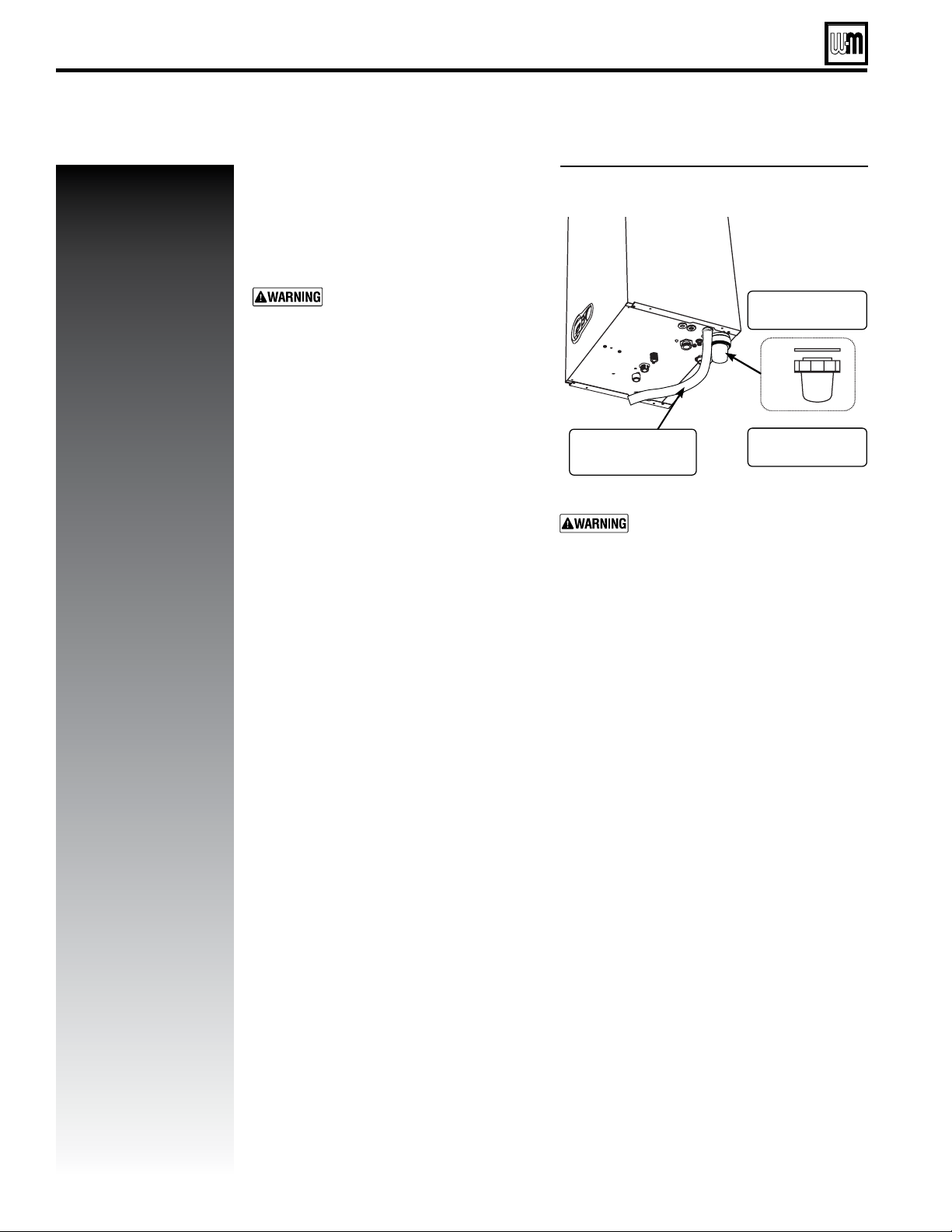
2. Inspect the boiler condensate trap, located
under the boiler (see Figure3). Check for
any sediment and clean out if necessary.
Make sure the trap has water in it.
3. Contact a boiler service technician if you
observe any problems.
Figure 3 Boiler condensate trap
Cap gasket
Condensate
drain line
Contact a boiler service technician
immediately if you nd the trap dry
(no water inside).
Clean out cap
8
Part number 550-100-326/0122
Page 9
AquaBalance
®
series
2
wall mount gas-fired water boiler – user information manual
User maintenance procedures (continued)
EVERY
6 MONTHS
Maintenance
Check boiler piping
1. Check all gas lines and smell for gas
odors. Perform gas leak inspection per
steps 1 through 7, Operating Instructions,
page10. If gas odor or leak is detected,
immediately shut down boiler following
procedures on page10. Call a qualied
service technician.
2. Visually inspect for water leaks around
all piping, circulators, relief valves and
other ttings.
3. Immediately call a qualied service technician to repair any leaks.
Have leaks xed at once by a
qualified service technician.
Continual fresh makeup water
will reduce boiler life. Minerals
can build up in the heat exchanger, reducing heat transfer
and causing overheating. Heat
exchanger failure can occur.
Do not use petroleum-based
cleaning or sealing com
pounds in boiler system. Se-
vere damage to boiler and
system components can occur,
resulting in possible severe
personal injury, death or substantial property damage.
Operate boiler relief valve
1. Before proceeding, verify that the relief
valve outlet has been piped to a safe place
of discharge, avoiding any possibility of
scalding from hot water.
3. Li the relief valve top lever slightly, allowing water to relieve through the valve
and discharge piping.
4. If water ows freely, release the lever and
allow the valve to seat. Watch the end of
the relief valve discharge pipe to ensure
that the valve does not weep aer the line
has had time to drain. If the valve weeps,
li the seat again to attempt to clean the
valve seat. If the valve continues to weep
aerwards, contact your qualied service
technician to inspect the valve and system.
5. If water does not ow from the valve
when you li the lever completely, the
valve or discharge line may be blocked.
Immediately shutdown the boiler, following the lighting instructions on the
inside jacket top. Call your qualified
service technician to inspect the boiler
and system.
To avoid water damage or
-
scalding due to valve operation,
a metal discharge line must
be connected to relief valve
outlet and run to a safe place
of disposal. is discharge line
must be installed by a qualied heating installer or service
technician in accordance with
the instructions in the Boiler
Manual
must be terminated so as to
eliminate possibility of severe
burns should the valve discharge.
. The discharge line
Part number 550-100-326/0122
2. Read the boiler pressure/temperature
gauge to make sure the system is pressurized.
9
Page 10
AquaBalance
®
series
2
wall mount gas-fired water boiler – user information manual
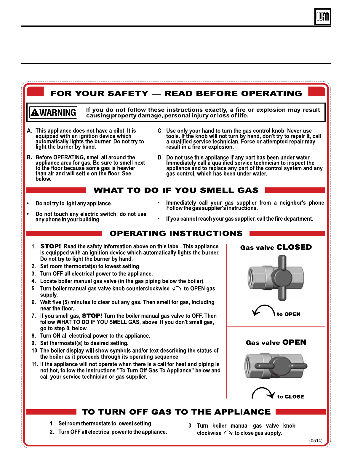
OPERATING INSTRUCTIONS
Figure 4 Operating instructions (see page 2 for location of manual gas valve)
10
Part number 550-100-326/0122
Page 11
AquaBalance
10
®
series
2
wall mount gas-fired water boiler – user information manual
CONTROL INTRODUCTION
Control Introduction
is boiler is a high-eciency condensing pre-mix appliance for
central heating and hot water production, running on Natural
gas or Liqueed Petroleum (Propane) gas, generating extremely
low emissions.
e boiler is constructed with a stainless steel heat exchanger
providing eective condensation of the water vapor contained
in the ue gases, permitting extremely high eciency.
Inside the boiler there is a premix burner with a large stainless
steel surface.
e boiler is sealed from the installation room: the air needed
for combustion is drawn from outside. e boiler also includes
a gas valve, pump, safety valve, ow sensor, dual safety and
control temperature sensor, a safety thermostat and a low water
pressure switch.
anks to the microprocessor control and adjustment system
with advanced self-diagnosis, unit operation is for the most part
automatic. e system heating temperature is automatically
governed by the control system.
e display continuously provides information on the unit’s
operating status and it is easily possible to obtain and adjust
temperature set-points, etc. or congure them. Any operating
problems associated with the boiler are immediately signalled by
the display and, if possible, corrected automatically.
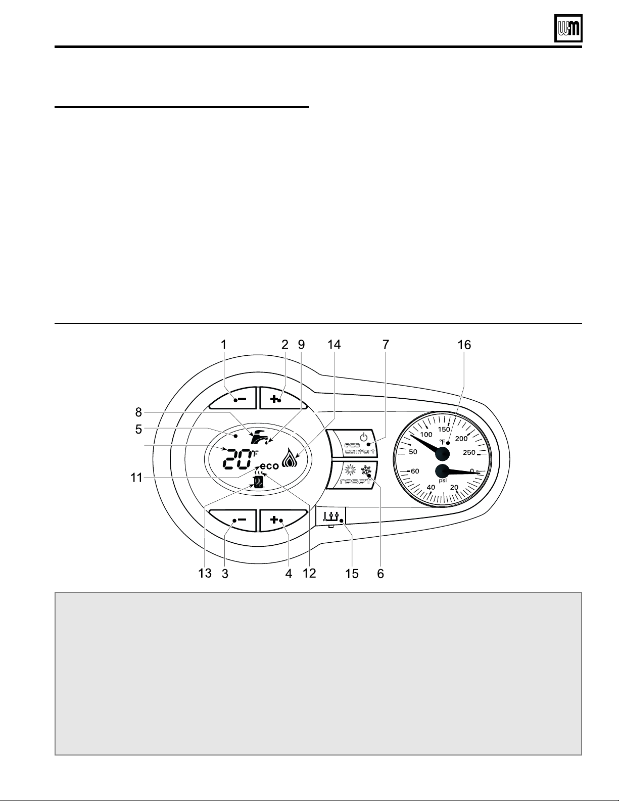
Figure 5 Control module
LEGEND for Figure 5
1 — Domestic Hot Water temperature setpoint decreasing button
2 — Domestic Hot Water temperature setpoint increasing button
3 — Central Heating Water temperature setpoint decreasing
button
4 — Central Heating Water temperature setpoint increasing button
5 — LCD Display
6 — Reset / OTC button
7 — Economy-Comfort On-O -Power button
8 — Domestic Hot Water symbol
9 — Domestic Hot Water mode operation
10 — Multi-function indication (Flashing during heat
exchanger protection)
11 — Economy symbol
12 — Central Heating mode operation
13 — Central Heating symbol
14 — Burner on and actual load indication (Flashing during
ame current supervision)
15 — Service tool connection
16 — Temperature-Pressure gauge
Part number 550-100-326/0122
11
Page 12

AquaBalance
®
series
2
wall mount gas-fired water boiler – user information manual
Part number 550-100-326/0122
 Loading...