

Page 1
CGa, CGi, CGs, EG,
EGH, LGB, PEG, PFG
Gas-Fired Boilers
User’s
Information
Manual
If the information in this manual is not followed exactly, a fire or
explosion may result, causing property damage, personal injury or
loss of life.
Do not store or use gasoline or other flammable vapors and liquids in the
vicinity of this or any other appliance.
WHAT TO DO IF YOU SMELL GAS
• Do not try to light any appliance.
• Do not touch any electrical switch; do not use any phone in your
building.
• Immediately call your gas supplier from a neighbor’s phone. Follow
the gas supplier’s instructions.
• If you cannot reach your gas supplier, call the fire department.
Installation and service must be performed by a qualified installer, service
technician or the gas supplier.
Part Number 550-110-592/0709
Page 2
CGa, CGi, CGs, EG, EGH, LGB, PEG, PFG Boilers
To . . . Read/use . . . Pages . . .
Learn
precautions
Warnings and definitions
1, 2, and 3
Prevent air
contamination
Read list of air contaminants you must avoid. If
found, either remove products permanently
or isolate boiler and provide outside combustion air.
3
Identify boiler
components
The illustration on page 4 or 5, will show you the
location of the main components.
4-5
Maintain
boiler
Set up a plan for maintaining the boiler using
the schedule included in this manual.
Schedule an annual start-up by a qualified service technician before every heating season.
6-12
Start — or —
Shutdown
boiler
Use the Lighting/Operating instruction sheet
for the gas valve installed on your boiler. Ask
your service technician if you are unsure which
one.
12-22
Troubleshoot
common
problems
Use the common problems/solutions table to
resolve typical heating system/boiler problems.
23
How to use this
manual . . .
Please read this page first
Hazard definitions
The following defined terms are used throughout this manual to bring attention to the presence
of hazards of various risk levels or to important information concerning the life of the product.
Indicates presence of hazards that will cause severe personal injury, death
Boiler service and
2
maintenance
or substantial property damage.
Indicates presence of hazards that can cause severe personal injury, death
or substantial property damage.
Indicates presence of hazards that will or can cause minor personal injury
or property damage.
Indicates special instructions on installation, operation or maintenance that
are important but not related to personal injury or property damage.
The Boiler manual is for use only by a qualified heating installer/service
technician. Refer only to this User’s Information Manual for your reference.
Improper installation, adjustment, alteration, service or maintenance can
cause property damage, personal injury (exposure to hazardous materials)
or loss of life. Installation and service must be performed by a qualified
installer, service agency or the gas supplier (who must read and follow the
supplied instructions before installing, servicing, or removing this boiler.
This boiler contains materials that have been identified as carcinogenic, or
possibly carcinogenic, to humans).
Part Number 550-110-592/0709
Page 3
STO P !! — Read before proceeding
Products to avoid
Spray cans containing chloro/fluorocarbons
Permanent wave solutions
Chlorinated waxes/cleaners
Chlorine-based swimming pool chemicals
Calcium chloride used for thawing
Sodium chloride used for water softening
Refrigerant leaks
Paint or varnish removers
Hydrochloric acid/muriatic acid
Cements and glues
Antistatic fabric softeners used in clothes
dryers
Chlorine-type bleaches, detergents, and
cleaning solvents found in household
laundry rooms
Adhesives used to fasten building products
and other similar products
Areas likely to have
contaminants
Dry cleaning/laundry areas and establishments
Swimming pools
Metal fabrication plants
Beauty shops
Refrigeration repair shops
Photo processing plants
Auto body shops
Plastic manufacturing plants
Furniture refinishing areas and establishments
New building construction
Remodeling areas
Garages with workshops
Failure to adhere to the guidelines on this page can result in severe personal injury, death or substantial
Air contamination
Service and maintenance
User’s Information Manual
property damage.
• Topreventpotentialofseverepersonalinjuryordeath,checkforproductsor
areas listed in table at right before installing boiler. If any of these contaminants
are found:
• removecontaminantspermanently. — OR —
• isolateboilerandprovideoutsidecombustionair.Seenational,provincialor
local codes for further information. — OR —
• forCGsboilersonly—combustionairmaybeductedfromoutsidetotheboiler
air intake.
• To avoid electric shock, disconnect electrical supply before performing
maintenance.
• Toavoidsevereburns,
• Youmustmaintain the boiler as outlined in the manual and have the boiler
started up and serviced at least annually by a qualified service technician
to ensure boiler/system reliability.
allow boiler to cool before performing maintenance.
Boiler operation
• Do not block flow of combustion or ventilation air to boiler. This boiler is
• Should
• Do not use this boiler if any part has been under water. Immediately call a
•
Boiler water
• DO NOT use petroleum-based cleaning or sealing compounds in boiler system.
•
• Continualfresh
•
equipped with a control which will automatically shut down the boiler should
air or vent be blocked. If vent or air blockage is easily accessible and removable,
remove it. The boiler should attempt to restart within an hour. If blockage is
not obvious or cannot be removed, have the boiler and system checked by a
qualified service technician.
overheating occur or gas supply fail to shut off, do not turn off or
disconnect electrical supply to pump. Instead,
location
external to the appliance.
shut off the gas supply at a
qualified service technician to inspect the boiler and to replace any part of the
control system and any gas control, which has been under water.
Have the building monitored when it is vacant for an extended period. Safety
controls can shut down the boiler at any time. The loss of heat can result in
significant damage due to freezing.
Water seal deterioration will occur, causing leakage between sections and damage
to heating system components. This can result in substantial property damage.
DO NOT use “homemade cures” or “boiler patent medicines”. Serious damage
to boiler, personnel and/or property may result.
sections reduces heat transfer, overheats cast iron, and causes section failure.
makeup water will reduce boiler life. Mineral buildup in
Addition of oxygen and other gases can cause internal corrosion. Leaks in boiler
or piping must be repaired at once to prevent makeup water.
Do not add cold water to hot boiler. Thermal shock can cause sections to
crack.
Part Number 550-110-592/0709
3
Page 4

CGa, CGi, CGs, EG, EGH, LGB, PEG, PFG Boilers
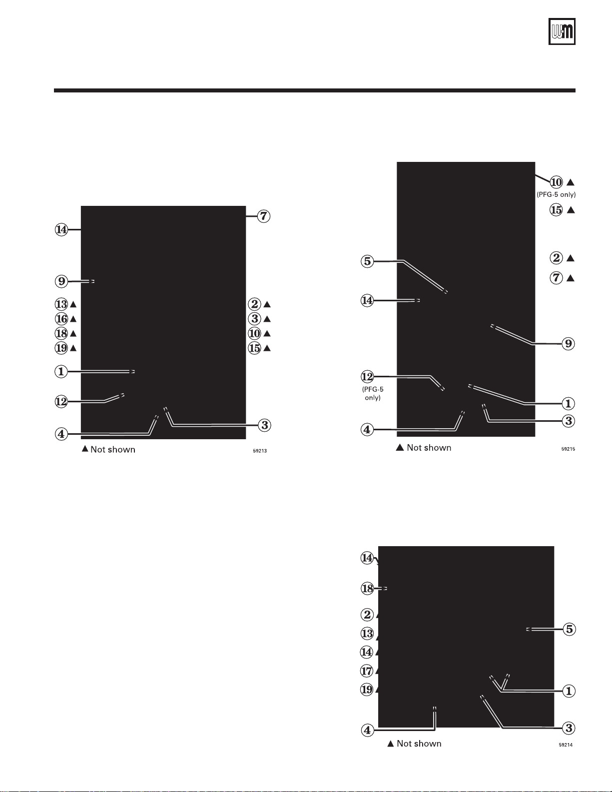
Boiler components
CGa CGi
CGs
4
1 Gas valve
2 Pilot burner
3 Main burner
4 Gas manifold/orifices
5 Control module
6 Inducer (CGi and CGs only)
7 Vent damper (CGa only)
8 Water temperature limit switch
9 Transformer
10 Spill switch (CGa only)
11 Air pressure switch (CGi and CGs only)
12 Rollout thermal fuse element
15 Draft hood (CGa only)
16 Circulator
17 Relief valve
18 Gauge (pressure or pressure/temperature)
Part Number 550-110-592/0709
Page 5
User’s Information Manual
EG/EGH PFG
1 Gas valve
2 Pilot burner
3 Main burner
4 Gas manifold/orifices
5 Control module
7 Vent damper
9 Transformer
10 Spill switch
12 Rollout thermal fuse element
13 Low water cutoff (steam boilers)
14 Limit control(s)
15 Draft hood
16 Circulator
18 Gauge (pressure or pressure/temperature)
19 Gauge glass (steam only)
Part Number 550-110-592/0709
LGB
5
Page 6
CGa, CGi, CGs, EG, EGH, LGB, PEG, PFG Boilers
Service technician
(covered in Boiler Manual — for use only by a
qualified service technician)
Owner maintenance
(see following pages for instructions)
A
NNNUAL
START
-
UP
Inspect:
• Reported problems
• Boiler area
• Air openings
• Flue gas vent system
• Pilot and main burner flames
• Water piping
• Boiler heating surfaces
• Burners, base and inlet air box
Service:
• Oiled-bearing circulators
Start-up:
• Perform start-up per manual
Check/test:
• Gas piping
• Cold fill and operating pressures
• Air vents and air elimination
• Limit controls and cutoffs
• Expansion tank
• Boiler relief valve
Review:
• Review with owner
Daily
• Check boiler area
• Check air openings
• Check boiler pressure/
temperature gauge
Monthly
• Check boiler interior piping
• Check venting system
• Check air vents
• Check boiler relief valve
• Check automatic air vents (if
used)
Periodically • Test low water cutoff (if used)
Every 6 months • Operate relief valve
End of season • Shut down procedure
Maintain boiler using schedule below
6
Tankless water heater (EG and EGH only)
If boiler is used to supply domestic hot water, limit
control should be set to supply adequate hot water.
Weil-McLain tankless heaters are rated at 200 °F boiler
water temperature. To get rated output, set low limit at
200 °F. Limit can be adjusted to meet system hot water
requirements. Differential can be set to 15 ° and adjusted
to control level. Lowering the differential will cause a
slight variation in water temperature but will decrease
burner on-off cycling. High limit should be set at least
20 ° above low limit.
Part Number 550-110-592/0709
Page 7
User’s Information Manual
User maintenance procedures
Boiler must be serviced & maintained
The boiler should be inspected and started annually, at
the beginning of the heating season, only by a qualified
service technician. In addition, the maintenance and
care of the boiler designated on page 6 and explained
on the following pages must be performed to assure
maximum boiler efficiency and reliability. Failure to
service and maintain the boiler and system could result
in equipment failure, causing possible severe personal
injury, death or substantial property damage.
Component information
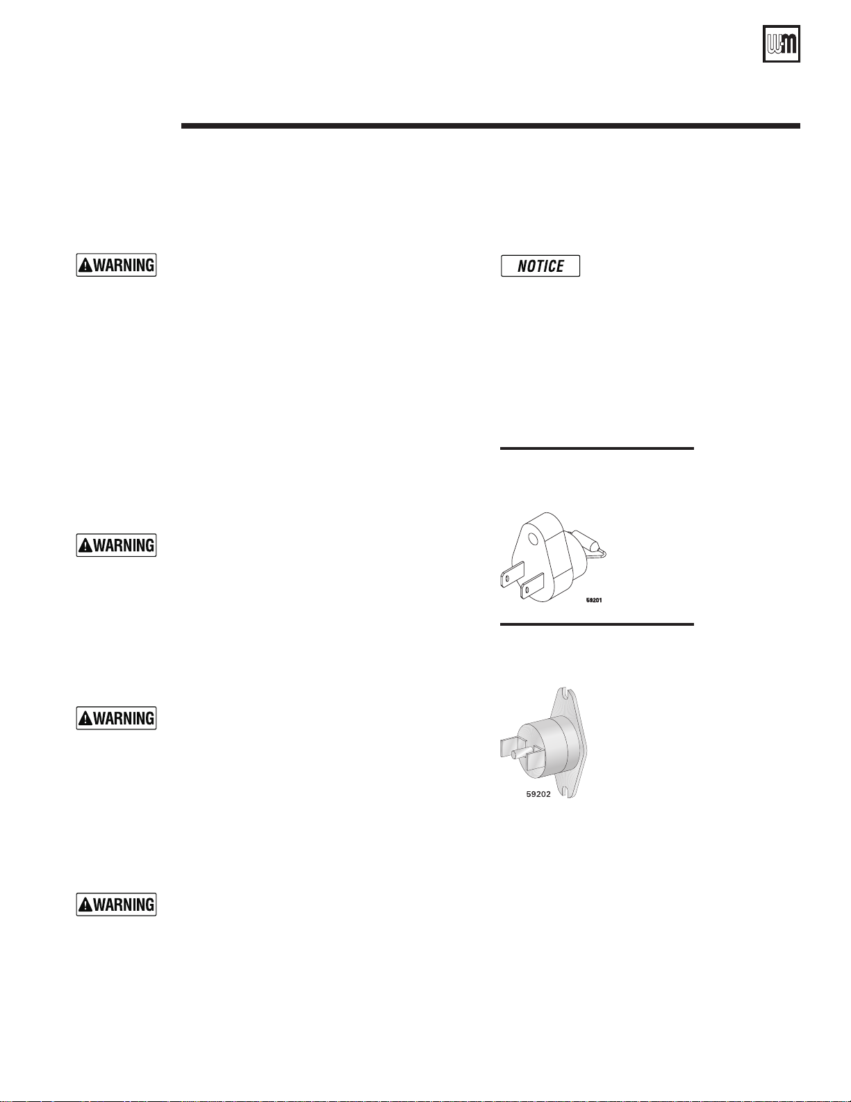
Rollout thermal fuse element
CGa, CGi, CGs, EG, EGH, PEG & PFG-5 only
Cuts off gas flowshould flame rollout occur. See
Figure 1.
Do not attempt to place boiler in operation if rollout
thermal fuse element cuts off gas flow. Immediately
call a service technician. Failure to do so can cause
severe personal injury, death or substantial property
damage.
Spill switch
CGa, EG, EGH, PEG & PFG-5 only
Cutsoffgasowshouldventsystembecomeblocked.
See Figure 2.
Figure 1
Rollout thermal fuse element
Figure 2
Spill switch
The following information provides
detailed instructions for completing
the maintenance items listed in
the maintenance schedule, page 6.
In addition to this maintenance,
the boiler must be serviced and
started up at the beginning of each
heating season by a qualified service
technician.
Do not attempt to place boiler in operation if spill switch
cuts off gas flow. Immediately call a service technician.
Failure to do so can cause severe personal injury, death
or substantial property damage.
❏ Check daily . . . . . . . . . . . . . . . . .
Boiler area
To prevent potential of severe personal injury, death
or substantial property damage, eliminate all materials
discussed below from the boiler vicinity. If found:
• Removeproducts immediately from the area.If
they have been there for an extended period, call
a qualified service technician to inspect the boiler
and vent system for possible damage from acid
corrosion.
• If products cannot be removed,immediately call
Part Number 550-110-592/0709
a qualified service technician to install an outside
combustion air source for the boiler (if not already
installed).
1. Combustible/flammable materials — Do not
store combustible materials, gasoline or any
other flammable vapors or liquids near the boiler.
Remove immediately if found.
2. Aircontaminants—Seelistingofcontaminantson
page 3.
7
Page 8
CGa, CGi, CGs, EG, EGH, LGB, PEG, PFG Boilers
❏ Check daily . . . . . . . . . . . . . . . . .
Pressure/temperature gauge
or pressure gauge (steam)
1. Waterboilers — Make sure thepressurereading
on the boiler pressure/temperature gauge does
not exceed 24 psig. Higher pressure may indicate a
problem with the expansion tank or gauge.
2. Steamboilers—Makesurethepressurereadingon
the boiler pressure gauge does not exceed 15 psig.
Higher pressure indicates a problem with the gauge
or limit control.
3. Contact a qualied service technician if problem
persists.
Air openings
1. Verify that combustion and ventilation air openings
to the boiler room and/or building are open and
unobstructed.
2. CGs boilers — Verifythat boiler vent discharge
and air intake are clean and free of obstructions.
Remove any debris on the air intake or flue exhaust
openings.
❏ Check monthly . . . . . . . . . . . . . . . .
Boiler piping
1. Visually inspect for leaks around piping, circulators,
relief valve and other fittings. Immediately call a
qualified service technician to repair any leaks.
Have leaks fixed at once by a qualified service technician.
Continual fresh makeup water will reduce boiler
life. Minerals can build up in sections, reducing heat
transfer, overheating cast iron, and causing section
If flame blows out or flickers severely, the vent
system must be checked for obstructions or
other causes of improper venting.
b. Verifytheventdamper (CGaandEGboilers)
opens before burners ignite.
3. Notify your qualified service technician at once if
you find any problem.
Boiler relief valve . . . . . . . . .
failure.
Do not use petroleum-based cleaning or sealing
compounds
and system components can occur, resulting in possible
severe personal injury, death or substantial property
in boiler system. Severe damage to boiler
Venting system
Failure to inspect the vent system as noted above and
have them repaired by a qualified service technician can
result in vent system failure, causing severe personal
injury or death.
1. Visually inspect all parts or the flue gas venting
system for any signs of blockage, leakage or joints
or deterioration of the piping.
2. CGa and EG boilers:
a. With boiler firing, hold a candle or match below
lower edge of draft hood “skirt.” If flame does
not blow out, but burns undisturbed, the vent
system is working properly.
8
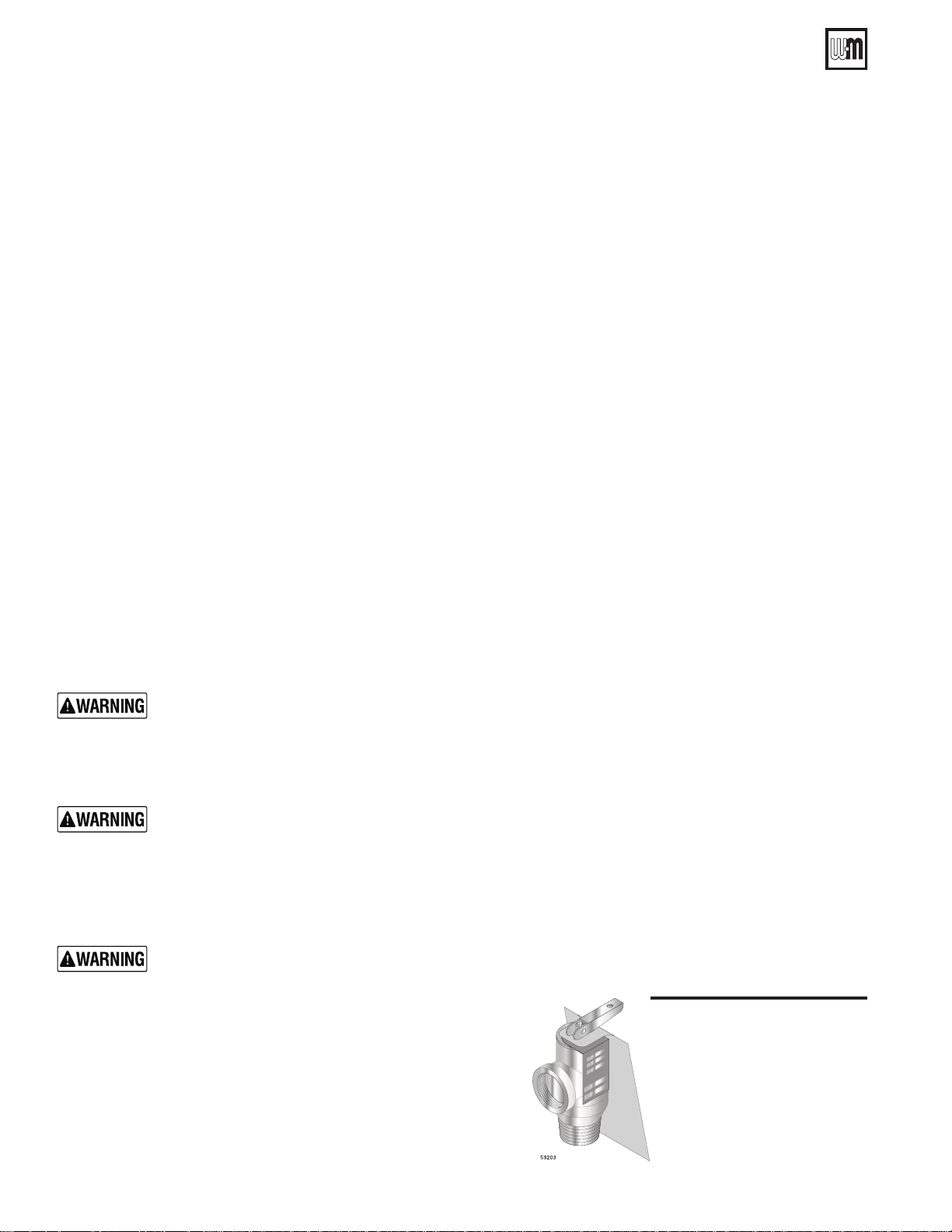
1. Inspect the boiler relief valve (see Figure 3) and the
relief valve discharge pipe for signs of weeping or
leakage.
2. If the relief valve often weeps:
• water boilers—theexpansiontankmaynot
be working properly.
• steam boilers —limitcontrolmaybesettoo
high or there may be system problems.
• Immediately contact your qualified service
technician to inspect the boiler and system.
Figure 3 Relief valve
Part Number 550-110-592/0709
Page 9
User’s Information Manual
❏ Check monthly . . . . . . . . . . . . . . . .
Automatic air vents (if used)
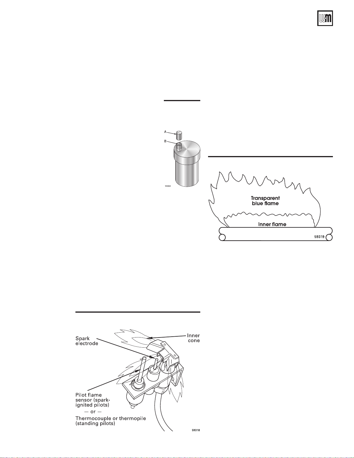
1. See Figure 4.
2. Rem ove the cap fr om any
aut o matic a ir vent i n t he
system and check operation by
depressing valve B slightly with
the tip of a screwdriver.
3. If the air vent valve appears to be
working freely and not leaking,
replace cap
way on.
4. Loosen cap A one turn to allow
vent to operate.
5. Have vent replaced if it does not
operate correctly.
A, twisting all the
Figure 4
Automatic air
vent
Pilot burner flame
Proper pilot flame (see Figure 5):
1. Blue flame.
2. Inner cone engulfing thermocouple or thermopile
(standing pilot) or pilot flame sensor (spark-ignited
pilot).
3. Thermocouple or thermopile, or pilot flame sensor
glowing cherry red.
Improper pilot flame:
1. Overred—Largeameliftingorblowingpastpilot
flame sensor.
2. Underred—Smallame.Innerconenotengulng
pilot flame sensor.
3. Lackofprimaryair—Yellowametip.
4. Incorrectly heated pilot flame sensor.
Main burner flame
Proper main burner flame (see Figure 6):
1. Yellow-orangestreaksmayappear(causedbydust).
Improper main burner flame:
1. Overred—Largeames.
2. Underred—Smallames.
3. Lack of primaryair— Yellow tipping on ames
(sooting will occur).
Figure 6 Main burner flame, typical
Clean vent termination & air
intake screens — CGs boilers only
1. Remove all lint and debris from both the boiler air
intake screen and the flue discharge screen.
Figure 5 Pilot burner and flame, typical
Part Number 550-110-592/0709
The boiler control module will sense blockage of
the air intake or flue and lockout if the blockage
is excessive. It will signal the failure by flashing the
appropriate indicator lights on the control board.
2. If removing the debris does not allow the boiler to
operate correctly afterwards, contact your qualified
service technician to inspect the boiler and vent/air
systems.
Check condensate drain
system
1. Inspect condensate drain fittings and tubing. Verify
that condensate can flow freely to drain.
9
Page 10
CGa, CGi, CGs, EG, EGH, LGB, PEG, PFG Boilers
❏ Service periodically . . . . . . . . . . . .
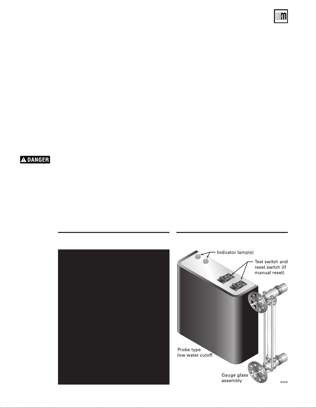
Test low water cutoff (all steam boilers)
(water boilers, if installed)
If the system is equipped with a low water cutoff, test the low water cutoff periodically during the heating season.
Float type — See Figure 7
1. Clean float type low water cutoff to clear float
chamber of sediment.
a. Open blowdown valve at bottom control.
b. Drain water into a bucket.
. Boiler pressure and temperature must be low to avoid
the potential of severe burns from steam or hot water.
2. Check float type low water cutoff for proper
operation.
a. Turn operating control to call for heat.
b. Before water gets hot, drain to bottom of gauge
glass. Boiler should shut off after water level
lowers a few inches.
c. Refill boiler to correct waterline. Boiler should
come back on.
Figure 7 Float type low water cutoff Figure 8 Probe type low water cutoff
Probe type— See Figure 8
1. Clean probe type low water cutoff for proper
operation.
a. Turn off power to boiler and wait 5 minutes.
b. Drain water to bottom of gauge glass.
c. Turn on power.
d. Set thermostat to call for heat. Red neon lamp
on lower water cutoff should light.
e. Wait 5 minutes. Boiler should not fire.
f. Refill boiler to correct water line. Red lamp
should go off.
g. Wait 5 minutes. Boiler should fire.
h. Return thermostat to normal setting.
10
Part Number 550-110-592/0709
Page 11
User’s Information Manual
❏ Service periodically continued . . . . . . .
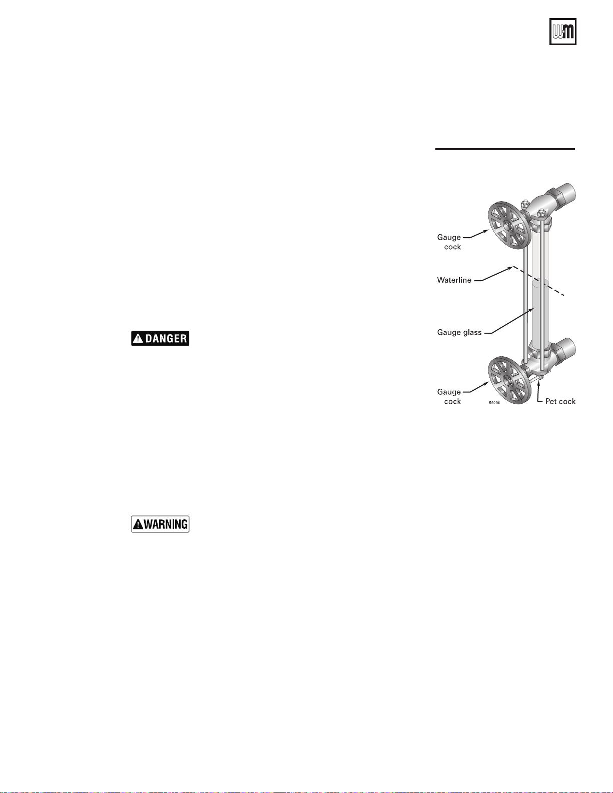
Clean gauge glass
Normal waterline on a steam boiler is halfway up gauge
glass.SeeFigure9.Cleanwhenneeded.
1. Closelowergaugecock.
2. Open pet cock.
3. Open lower gauge cock and allow a small amount
of water to flush out through open pet cock.
4. Closepetcock.
5. Open lower gauge cock.
Boiler pressure must be low to eliminate potential of
severe burns.
6. If gauge glass breaks, close both gauge cocks and call
a qualified service technician to replace gauge glass.
Do not replace with thin glass tubing.
Figure 9 Gauge glass
❏ Service every 6 months . . . . . . . . .
Operate boiler relief valve
To avoid water damage or scalding
due to valve operation, a metal
discharge line must be connected
to relief valve outlet and run to a
safe place of disposal. This discharge
line must be installed by a qualified
heating installer or service technician
in accordance with the instructions
in the Boiler Manual.
The d i s c h a r g e li n e mu s t be
te rminated so as to eliminate
possibility of severe burns should
the valve discharge.
1. Before proceeding, verify that the relief valve outlet
has been piped to a safe place of discharge, avoiding
any possibility of scalding from hot water.
2. Read the boiler pressure/temperature gauge to make
sure the system is pressurized.
3. Lift the relief valve top lever slightly, allowing water
to relieve through the valve and discharge piping.
4. If water flows freely, release the lever and allow
the valve to seat. Watch the end of the relief valve
discharge pipe to ensure that the valve does not
weep after the line has had time to drain. If the valve
weeps, lift the seat again to attempt to clean the
valve seat. If the valve continues to weep afterwards,
contact your qualified service technician to inspect
the valve and system.
5. If water does not flow from the valve when you
lift the lever completely, the valve or discharge line
may be blocked. Immediately shutdown the boiler,
following the instructions on the inside jacket top
Lighting Instructions. Callyour qualiedservice
technician to inspect the boiler and system.
Part Number 550-110-592/0709
11
Page 12
CGa, CGi, CGs, EG, EGH, LGB, PEG, PFG Boilers
Standing pilot Models Page Spark-ignited pilot Models Page
Honeywell VR8200/VR8300
CGa-25 – CGa-8
EG-30 – EG-65
PEG-30 – PEG-55
13
Honeywell VR8204/VR8304
CGa-25 – CGa-8
EG-30 – EG-75
PEG-30 – PEG-55
PFG-5
16
CGi, CGs
21
White-Rodgers 36E
CGa-25 – CGa-6
EG-30 – EG-50
PEG-30 – PEG-50
17
Robertshaw 7200
CGa-25 – CGa-6
EG-30 – EG-50
PEG-30 – PEG-50
14
CGi
CGs
21
Robertshaw 7000ERHC
EG-75
EGH-85, EGH-95
PFG-6, PFG-7
15
White-Rodgers 36C
CGa-7, CGa-8
EG-55 – EG-75
PEG-55, PFG-5
18
CGi, CGs
21
Robertshaw 7200
CGa-25 – CGa-6
EG-30 – EG-50
PEG-30 – PEG-50
19
Robertshaw 7000 DERHC
EGH-85 – EGH-125
PFG-6 – PFG-8
20
--
LGB
22
❏ End-of-season shutdown . . . . . . . .
Follow boiler shutdown procedure
1. Follow “TO TURN OFF GAS TO APPLIANCE” on the
Lighting/Operating instructions
on the inside of
thejacketpanel.Youwillalsondtheseinstructions
on pages 13 through 22 of this manual.
Use the Lighting/Operating instruction for the gas
valve model installed on the boiler.
2. Do not drain system unless exposure to freezing
temperatures will occur.
3. Do not drain the system if it is filled with an
antifreeze solution.
4. Do not shut down boilers used for domestic water
heating. They must operate year-round.
Propane gas odorant
Propane boilers only—Yourpropanesuppliermixesanodorantwiththepropanetomakeitspresencedetect-
able. In some instances, the odorant can fade and the gas may no longer have an odor.
• Propanegascanaccumulateatoorlevel.Smellneartheoorforthegasodorantoranyunusualodor.
If you suspect a leak, do not attempt to light the pilot.
• Usecautionwhenattemptingtolightthepropanepilot.Thisshouldbedonebyaqualiedservice
technician, particularly if pilot outages are common.
• Periodicallychecktheodorantlevelofyourgas.
• Inspectboilerandsystematleastyearlytomakesureallgaspipingisleak-tight.
• Consultyourpropanesupplierregardinginstallationofagasleakdetector.Therearesomeproductson
themarketintendedforthispurpose.Yoursuppliermaybeabletosuggestanappropriatedevice.
Lighting instructions
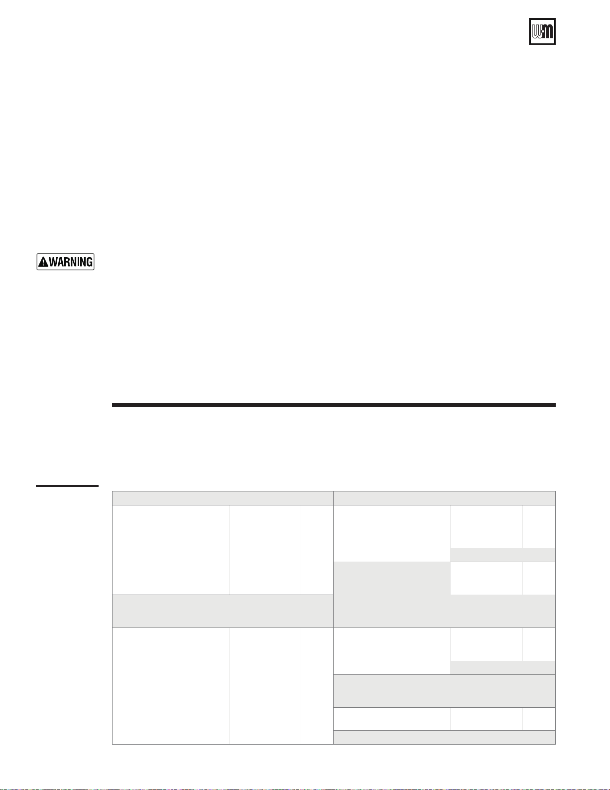
Use Table 2 below to locate the correct Lighting/Operating instruction for the gas valve model installed on your
boiler.
Table 2
Lighting
/Operating
instruction
12
guide
Part Number 550-110-592/0709
Page 13

User’s Information Manual
Lighting instructions
• Standing pilot
• Gas valve — Honeywell VR8200/VR8300
FOR YOUR SAFETY READ BEFORE LIGHTING
If you do not follow these instructions exactly, a fire or explosion may result
causing property damage, personal injury or loss of life.
A. This appliance has a pilot, which must be lighted
by hand. When lighting the pilot, follow these
instructions exactly.
B. BEFORE LIGHTING, s mell a ll ar ound the
appliance area for gas. Be sure to smell next to the
floor because some gas is heavier than air and will
settle on the floor. See below.
WHAT TO DO IF YOU SMELL GAS
• Donottrytolightanyappliance.
• Donottouchanyelectricswitch;donotuseanyphonein
your building.
C. Useonlyyourhand topushdowntheresetbuttonorturn thegas
control knob. Never use tools. If the knob or reset button will not
operate by hand, don’t try to repair it, call a qualified service technician. Force or attempted repair may result in a fire or explosion.
D. Do not use this appliance if any part has been under water.
Immediately call a qualified service technician to inspect the appliance
and to replace any part of the control system and any gas control,
which has been under water.
• Immediatelycallyourgassupplierfromaneighbor’sphone.
Follow the gas supplier’s instructions.
• If you cannot reach your gas supplier, call the fire
department.
CGa, EG-30 to EG-65,
PEG-30 to PEG-55
LIGHTING INSTRUCTIONS
1. STOP! Read the safety information above on this label.
2. Set the thermostat to lowest setting.
3. Turn off all electrical power to the appliance.
4. Remove front panel.
5. Turn gas control knob clockwise to “OFF”.
6. Wait five (5) minutes to clear out any gas. Then smell for
gas, including near the floor. If you smell gas, STOP! Follow
“B” in the safety information above. If you don’t smell gas,
go to the next step.
7. Remove access panel located above burners.
8. Find pilot - follow metal tube from gas control.
The pilot is between two burners behind the access
panel.
9. Turn gas control knob counterclockwise to
“PILOT”.
10.Pushinredresetbuttonandhold.Immediately
lightthepilotwithamatch.Continuetoholdresetbutton
in for about one (1) minute after the pilot is lit.
11.Releasereset button. Pilotshouldremainlit.If pilotgoes
out, repeat steps 6 through 13.
• If reset button stays depressed after release, stop
and immediately call your service technician or gas
supplier.
• Ifthe pilotwillnotstaylit afterseveraltries,turn the
gas control knob clockwise
service technician or gas supplier.
12. Replace access panel.
13. Turn gas control knob counterclockwise
14. Turn on all electric power to the appliance.
15. Set thermostat to desired setting.
16. Replace front panel.
to “OFF” and call your
to “ON”.
TO TURN OFF GAS TO THE APPLIANCE
1. Set the thermostat to lowest setting.
2. Turn off all electric power to the appliance if service is to
be performed.
Part Number 550-110-592/0709
3. Remove front panel.
4. Turn gas control knob clockwise
5. Replace front panel.
to “OFF”.
550-223-038(0906)
13
Page 14
CGa, CGi, CGs, EG, EGH, LGB, PEG, PFG Boilers
Lighting instructions
• Standing pilot
• Gas valve — Robertshaw 7200
FOR YOUR SAFETY READ BEFORE LIGHTING
If you do not follow these instructions exactly, a fire or explosion may result
causing property damage, personal injury or loss of life.
A. This appliance has a pilot, which must be lighted
by hand. When lighting the pilot, follow these
instructions exactly.
B. BEFORE LIGHTING, smell all around the
appliance area for gas. Be sure to smell next to the
floor because some gas is heavier than air and will
settle on the floor. See below.
WHAT TO DO IF YOU SMELL GAS
• Donottrytolightanyappliance.
• Donottouchanyelectricswitch;donotuseanyphonein
your building.
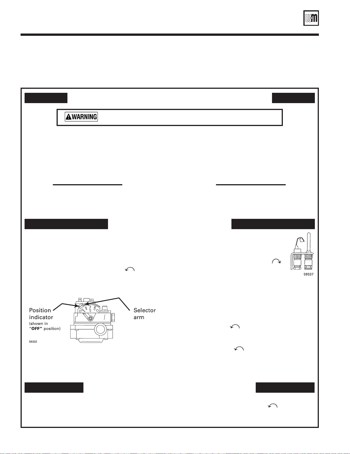
C. Useonlyyourhandtodepresstheselectorarm.Neverusetools.If
D. Do not use this appliance if any part has been under water.
Immediately call a qualified service technician to inspect the appliance
CGa-25 to CGa-6,
EG-30 to EG-50,
PEG-30 to PEG-50
the selector arm will not move by hand, don’t try to repair it, call a
qualified service technician. Force or attempted repair may result in
a fire or explosion.
and to replace any part of the control system and any gas control,
which has been under water.
• Immediatelycallyourgassupplierfromaneighbor’sphone.
Follow the gas supplier’s instructions.
• If you cannot reach your gas supplier, call the fire
department.
LIGHTING INSTRUCTIONS
STOP! Read the safety information above on this label.
1.
2. Set the thermostat to lowest setting.
3. Turn off all electrical power to the appliance.
4. Remove front panel.
5. Depress and move selector arm left
Note: Selector arm cannot be moved to
selector arm is depressed slightly. Do not force.
6. Wait five (5) minutes to clear out any gas. Then smell for
gas, including near the floor. If you smell gas,
“B” in the safety information above. If you don’t smell gas,
go to the next step.
7. Remove access panel located above burners.
to “OFF”.
“OFF” unless
STOP! Follow
TO TURN OFF GAS TO THE APPLIANCE
8. Find pilot - follow metal tube from gas control. The pilot is between two burners behind
the access panel.
9. Move selector arm on gas control right
to “SET” position.
10. Hold selector arm in “SET” position and immediately
lightthepilotwithamatch.Continuetoholdselectorarm
to “SET” for about one-half (1/2) minute after the pilot is
lit.
11. Release selector arm. If pilot does not remain lit, repeat
steps 6 through 13.
• Ifthe pilot will not staylit after severaltries, move
selector arm left
technician or gas supplier.
12. Replace access panel.
13. Turn selector arm left
14. Turn on all electric power to the appliance.
15. Set thermostat to desired setting.
16. Replace front panel.
to “OFF” and call your service
to “ON”.
1. Set the thermostat to lowest setting.
2. Turn off all electric power to the appliance if service is to
be performed.
14
3. Remove front panel.
4. Depress and move selector arm left
Do not force.
5. Replace front panel.
Part Number 550-110-592/0709
to “OFF”.
550-223-039(0906)
Page 15
User’s Information Manual
Lighting instructions
• Standing pilot
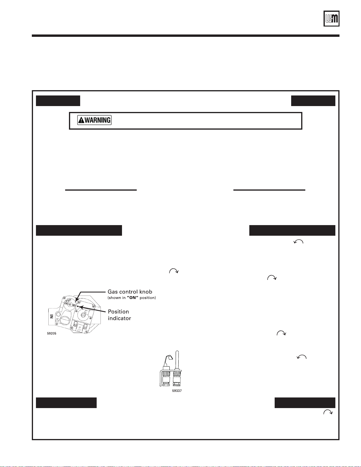
• Gas valve — Robertshaw 7000ERHC
FOR YOUR SAFETY READ BEFORE LIGHTING
If you do not follow these instructions exactly, a fire or explosion may result
causing property damage, personal injury or loss of life.
A. This appliance has a pilot, which must be lighted
by hand. When lighting the pilot, follow these
instructions exactly.
B. BEFORE LIGHTING, smell all around the
appliance area for gas. Be sure to smell next to the
floor because some gas is heavier than air and will
settle on the floor. See below.
WHAT TO DO IF YOU SMELL GAS
• Donottrytolightanyappliance.
• Donottouchanyelectricswitch;donotuseanyphonein
your building.
C. Useonlyyourhandtodepressorturnthegascontrolknob.Never
use tools. If the selector arm will not depress or move by hand, don’t
try to repair it, call a qualified service technician. Force or attempted
repair may result in a fire or explosion.
D. Do not use this appliance if any part has been under water.
Immediately call a qualified service technician to inspect the appliance
and to replace any part of the control system and any gas control,
which has been under water.
EG-75, EGH-85, EGH-95,
PFG-6, PFG-7
• Immediatelycallyourgassupplierfromaneighbor’sphone.
Follow the gas supplier’s instructions.
• If you cannot reach your gas supplier, call the fire
department.
LIGHTING INSTRUCTIONS
1. STOP! Read the safety information above on this label.
2. Set the thermostat to lowest setting.
3. Turn off all electrical power to the appliance.
4. Remove front panel.
5. Depress gas control knob slightly and turn clockwise
to “OFF”. Note:Gascontrolknobcannotbeturnedto
“OFF” unless knob is depressed slightly. Do not force.
6. Wait five (5) minutes to clear out any gas. Then smell for
gas, including near the floor. If you smell gas,
Follow “B” in the safety information above.
If you don’t smell gas, go to the next step.
7. Remove access panel located above burners.
8. Findpilot—followmetaltubefromgascontrol. The pilot is between two burners behind
the access panel.
STOP!
9. Turn gas control knob counterclockwise to “PILOT”.
10. Depress gas control knob and hold. Immediately light the
pilotwithamatch.Continuetoholdgascontrolknobin
for about one (1) minute after the pilot is lit.
• Ifpilotcanbelitwithoutdepressinggascontrolknob,
turn gas knob clockwise to “OFF” and call your
service technician or gas supplier.
11.Releasegascontrolknob.Pilotshouldremainlit.Ifpilot
goes out, repeat steps 5 through 11.
• Ifgascontrolknobstaysdepressedafterrelease,stop
and immediately call your service technician or gas
supplier.
• Ifthepilotwillnotstaylitafterseveraltries,turnthe
gas control knob clockwise to “OFF” and call
your service technician or gas supplier.
12. Replace access panel.
13. Turn gas control knob counterclockwise to “ON”.
14. Turn on all electric power to the appliance.
15. Set thermostat to desired setting.
16. Replace front panel.
TO TURN OFF GAS TO THE APPLIANCE
1. Set the thermostat to lowest setting.
2. Turn off all electric power to the appliance if service is to
be performed.
3. Remove front panel.
Part Number 550-110-592/0709
4. Depress gas control knob slightly and turn clockwise
to “OFF”.
5. Replace front panel.
550-223-081(0609)
15
Page 16
CGa, CGi, CGs, EG, EGH, LGB, PEG, PFG Boilers
Operating instructions
• Spark-ignited pilot
• Gas valve
A. This appliance is equipped with an ignition device
which automatically lights the pilot. Do not try
to light the pilot by hand.
B.
BEFORE OPERATING, smell all around the
appliance area for gas. Be sure to smell next to the
floor because some gas is heavier than air and will
settle on the floor. See below.
• Donottrytolightanyappliance.
• Donottouchanyelectricswitch;donotuseanyphonein
your building.
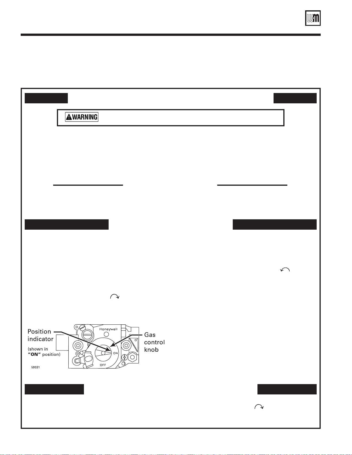
— Honeywell VR8204/VR8304
FOR YOUR SAFETY READ BEFORE OPERATING
If you do not follow these instructions exactly, a fire or explosion may result
causing property damage, personal injury or loss of life.
C. Useonlyyourhandtoturnthegascontrolknob.Neverusetools.If
D. Do not use this appliance if any part has been under water.
Immediately call a qualified service technician to inspect the appliance
WHAT TO DO IF YOU SMELL GAS
CGa, EG-30 to EG-75,
PEG-30 to PEG-55,
PFG-5
the knob will not turn by hand, don’t try to repair it, call a qualified
service technician. Force or attempted repair may result in a fire or
explosion.
and to replace any part of the control system and any gas control,
which has been under water.
• Immediatelycallyourgassupplierfromaneighbor’sphone.
Follow the gas supplier’s instructions.
• If you cannot reach your gas supplier, call the fire
department.
OPERATING INSTRUCTIONS
1. STOP! Read the safety information above on this label.
2. Set the thermostat to lowest setting.
3. Turn off all electrical power to the appliance.
4. Remove from panel.
5. This appliance is equipped with an ignition device which
automatically lights the pilot.
by hand.
6. Turn gas control knob clockwise
Do not try to light the pilot
to “OFF”.
TO TURN OFF GAS TO THE APPLIANCE
1. Set the thermostat to lowest setting.
2. Turn off all electric power to the appliance if service is to
be performed.
7. Wait five (5) minutes to clear out any gas. Then smell for
gas, including near the floor. If you smell gas,
“B” in the safety information above. If you don’t smell gas,
go to the next step.
8. Turn gas control knob counterclockwise to “ON”.
9. Turn on all electric power to the appliance.
10. Set thermostat to desired setting.
11. If the appliance will not operate, follow the instructions
To Turn Off Gas To The Appliance and call your service
technician or gas supplier.
12. Replace front panel.
3. Remove front panel.
4. Turn gas control knob clockwise
5. Replace front panel.
to “OFF”. Do not force.
STOP! Follow
550-223-041(0906)
16
Part Number 550-110-592/0709
Page 17
User’s Information Manual
Operating instructions
• Spark-ignited pilot
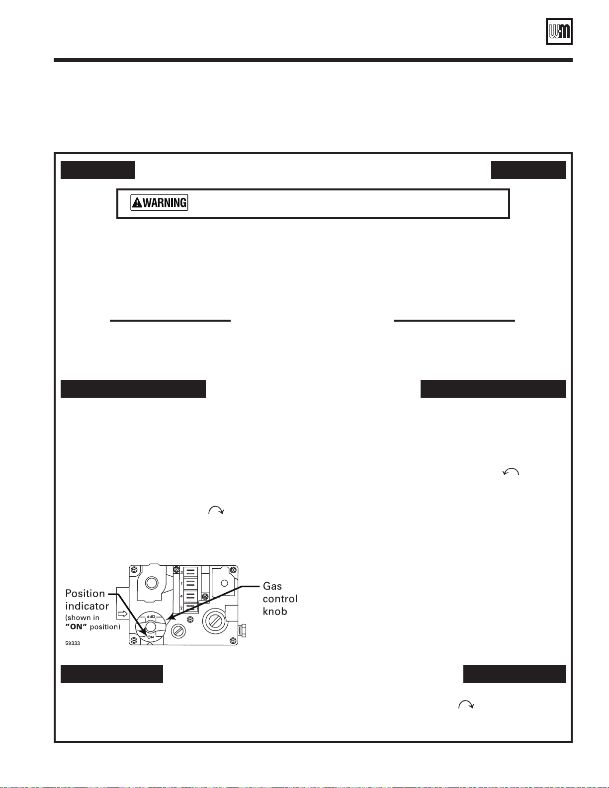
• Gas valve — White-Rodgers 36E
FOR YOUR SAFETY READ BEFORE OPERATING
If you do not follow these instructions exactly, a fire or explosion may result
causing property damage, personal injury or loss of life.
A. This appliance is equipped with an ignition device
which automatically lights the pilot. Do not try
to light the pilot by hand.
B. BEFORE OPERATING, smell all around the
appliance area for gas. Be sure to smell next to the
floor because some gas is heavier than air and will
settle on the floor. See below.
WHAT TO DO IF YOU SMELL GAS
• Donottrytolightanyappliance.
• Donottouchanyelectricswitch;donotuseanyphonein
your building.
C. Useonlyyourhandtoturnthegascontrolknob.Neverusetools.If
D. Do not use this appliance if any part has been under water.
Immediately call a qualified service technician to inspect the appliance
CGa-25 to CGa-6,
EG-30 to EG-50,
PEG-30 to PEG-50
the knob will not turn by hand, don’t try to repair it, call a qualified
service technician. Force or attempted repair may result in a fire or
explosion.
and to replace any part of the control system and any gas control,
which has been under water.
• Immediatelycallyourgassupplierfromaneighbor’sphone.
Follow the gas supplier’s instructions.
• If you cannot reach your gas supplier, call the fire
department.
OPERATING INSTRUCTIONS
1.
STOP! Read the safety information above on this label.
2. Set the thermostat to lowest setting.
3. Turn off all electrical power to the appliance.
4. Remove front panel.
5. This appliance is equipped with an ignition device which
automatically lights the pilot.
by hand.
6. Turn gas control knob clockwise
Do not try to light the pilot
to “OFF”.
TO TURN OFF GAS TO THE APPLIANCE
1. Set the thermostat to lowest setting.
2. Turn off all electric power to the appliance if service is to
be performed.
7. Wait five (5) minutes to clear out any gas. Then smell for
gas, including near the floor. If you smell gas, STOP! Follow
“B” in the safety information above. If you don’t smell gas,
go to the next step.
8. Turn gas control knob counterclockwise to “ON”.
9. Turn on all electric power to the appliance.
10. Set thermostat to desired setting.
11. If the appliance will not operate, follow the instructions
To Turn Off Gas To The Appliance and call your service
technician or gas supplier.
12. Replace front panel.
3. Remove front panel.
4. Turn gas control knob clockwise to “OFF”. Do not force.
5. Replace front panel.
550-223-042(0906)
Part Number 550-110-592/0709
17
Page 18
CGa, CGi, CGs, EG, EGH, LGB, PEG, PFG Boilers
Operating instructions
• Spark-ignited pilot
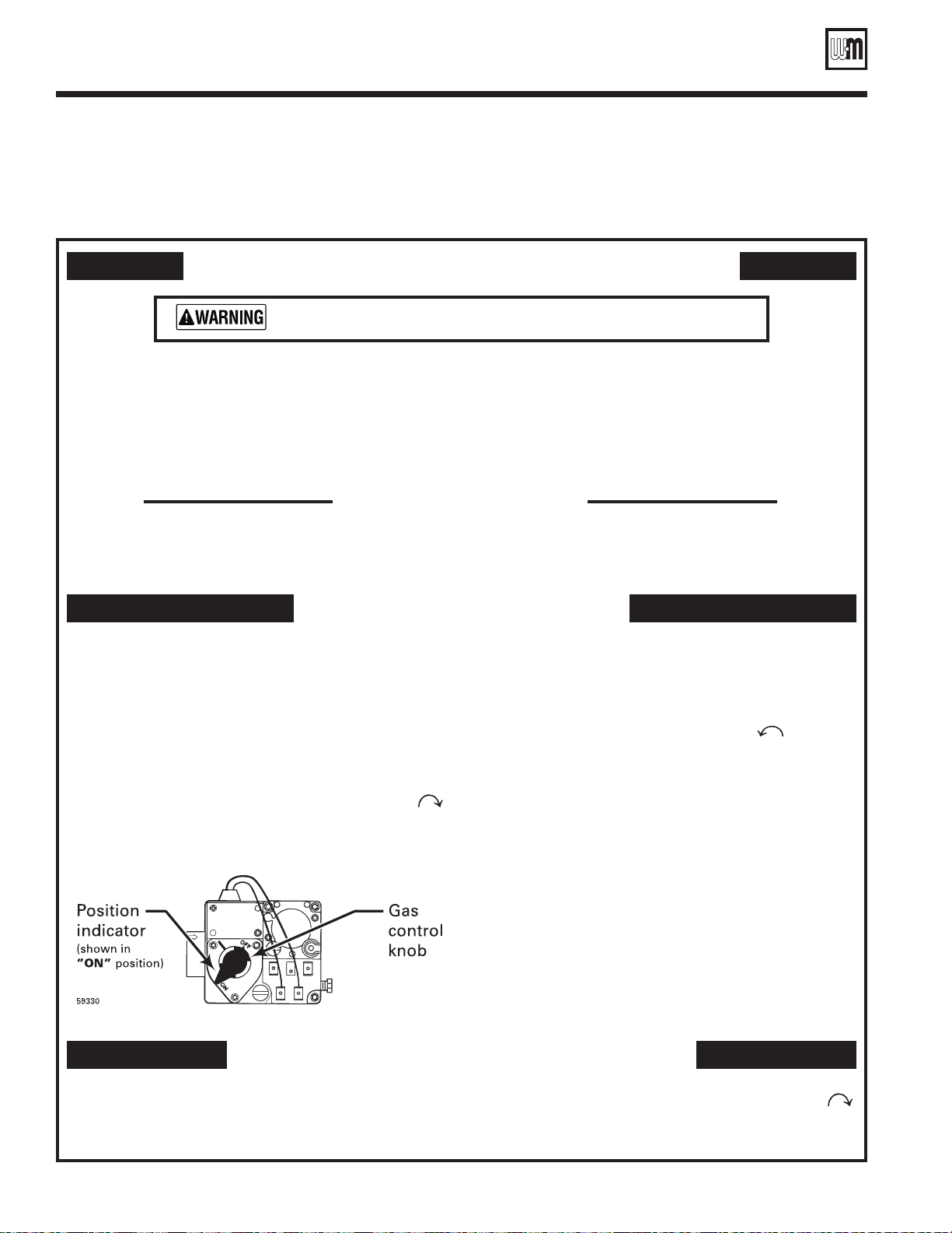
• Gas valve — White-Rodgers 36C
FOR YOUR SAFETY READ BEFORE OPERATING
If you do not follow these instructions exactly, a fire or explosion may result
causing property damage, personal injury or loss of life.
A. This appliance is equipped with an ignition device
which automatically lights the pilot. Do not try
to light the pilot by hand.
B. BEFORE OPERATING, smell all around the
appliance area for gas. Be sure to smell next to the
floor because some gas is heavier than air and will
settle on the floor. See below.
WHAT TO DO IF YOU SMELL GAS
• Donottrytolightanyappliance.
• Donottouchanyelectricswitch;donotuseanyphonein
your building.
C. Useonlyyourhandtodepressorturnthegascontrolknob.Never
D. Do not use this appliance if any part has been under water.
Immediately call a qualified service technician to inspect the appliance
CGa-7, CGa-8,
EG-55 to EG-75,
PEG-55, PFG-5
use tools. If the knob will not depress or turn by hand, don’t try to
repair it, call a qualified service technician. Force or attempted repair
may result in a fire or explosion.
and to replace any part of the control system and any gas control,
which has been under water.
• Immediatelycallyourgassupplierfromaneighbor’sphone.
Follow the gas supplier’s instructions.
• If you cannot reach your gas supplier, call the fire
department.
OPERATING INSTRUCTIONS
STOP! Read the safety information above on this label.
1.
2. Set the thermostat to lowest setting.
3. Turn off all electrical power to the appliance.
4. Remove front panel.
5. This appliance is equipped with an ignition device which
automatically lights the pilot. Do not try to light the pilot
by hand.
6. Depress gas control knob slightly and turn clockwise
to “OFF”. Note: Knob cannot be turned to “OFF” unless
knob is depressed slightly. Do not force.
TO TURN OFF GAS TO THE APPLIANCE
1. Set the thermostat to lowest setting.
2. Turn off all electric power to the appliance if service is to
be performed.
7. Wait five (5) minutes to clear out any gas. Then smell for
gas, including near the floor. If you smell gas,
“B” in the safety information above. If you don’t smell gas,
go to the next step.
8. Turn gas control knob counterclockwise to “ON”.
9. Turn on all electric power to the appliance.
10. Set thermostat to desired setting.
11. If the appliance will not operate, follow the instructions
To Turn Off Gas To The Appliance and call your service
technician or gas supplier.
12. Replace front panel.
3. Remove front panel.
4. Depress gas control knob slightly and turn clockwise
to “OFF”. Do not force.
5. Replace front panel.
STOP! Follow
550-223-043(0906)
18
Part Number 550-110-592/0709
Page 19
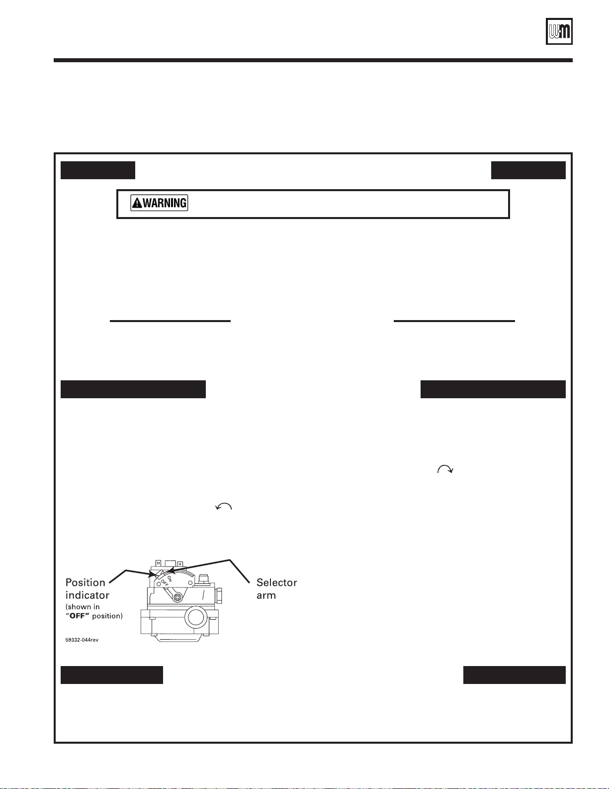
User’s Information Manual
Operating instructions
• Spark-ignited pilot
• Gas valve — Robertshaw 7200
FOR YOUR SAFETY READ BEFORE OPERATING
If you do not follow these instructions exactly, a fire or explosion may result
causing property damage, personal injury or loss of life.
A. This appliance is equipped with an ignition device
which automatically lights the pilot. Do not try
to light the pilot by hand.
B. BEFORE OPERATING, smell all around the
appliance area for gas. Be sure to smell next to the
floor because some gas is heavier than air and will
settle on the floor. See below.
WHAT TO DO IF YOU SMELL GAS
• Donottrytolightanyappliance.
• Donottouchanyelectricswitch;donotuseanyphonein
your building.
C. Useonlyyourhandtodepressormovetheselectorarm.Neveruse
D. Do not use this appliance if any part has been under water.
Immediately call a qualified service technician to inspect the appliance
CGa-25 to CGa-6,
EG-30 to EG-50,
PEG-30 to PEG-50
tools. If the selector arm will not depress or move by hand, don’t try to
repair it, call a qualified service technician. Force or attempted repair
may result in a fire or explosion.
and to replace any part of the control system and any gas control,
which has been under water.
• Immediatelycallyourgassupplierfromaneighbor’sphone.
Follow the gas supplier’s instructions.
• If you cannot reach your gas supplier, call the fire
department.
OPERATING INSTRUCTIONS
1.
STOP! Read the safety information above on this label.
2. Set the thermostat to lowest setting.
3. Turn off all electrical power to the appliance.
4. Remove front panel.
5. This appliance is equipped with an ignition device which
automatically lights the pilot. Do not try to light the pilot
by hand.
6. Depress and move selector arm left to “OFF”. Note:
Selector arm cannot be moved to “OFF” unless selector
arm is depressed slightly. Do not force.
TO TURN OFF GAS TO THE APPLIANCE
1. Set the thermostat to lowest setting.
2. Turn off all electric power to the appliance if service is to
be performed.
7. Wait five (5) minutes to clear out any gas. Then smell for
gas, including near the floor. If you smell gas, STOP! Follow
“B” in the safety information above. If you don’t smell gas,
go to the next step.
8. Move selector arm right to “ON”.
19. Turn on all electric power to the appliance.
10. Set thermostat to desired setting.
11. If the appliance will not operate, follow the instructions
“To Turn Off Gas To The Appliance” and call your service
technician or gas supplier.
12. Replace front panel.
3. Remove front panel.
4. Depress and move selector arm to “OFF”. Do not force.
5. Replace front panel.
550-223-044(0906)
Part Number 550-110-592/0709
19
Page 20
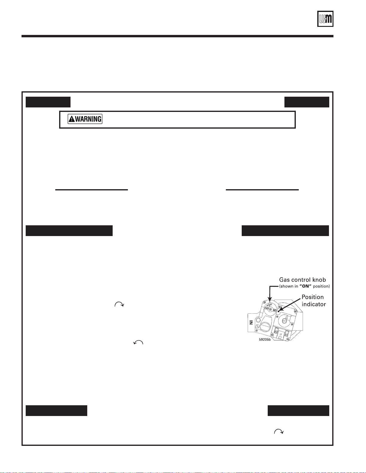
CGa, CGi, CGs, EG, EGH, LGB, PEG, PFG Boilers
Operating instructions
• Spark-ignited pilot
• Gas valve — Robertshaw 7000DERHC
FOR YOUR SAFETY READ BEFORE OPERATING
If you do not follow these instructions exactly, a fire or explosion may result
causing property damage, personal injury or loss of life.
A. This appliance is equipped with an ignition device
which automatically lights the pilot. Do not try
to light the pilot by hand.
B. BEFORE OPERATING, smell all around the
appliance area for gas. Be sure to smell next to the
floor because some gas is heavier than air and will
settle on the floor. See below.
WHAT TO DO IF YOU SMELL GAS
• Donottrytolightanyappliance.
• Donottouchanyelectricswitch;donotuseanyphonein
your building.
C. Useonlyyourhandtoturnthegascontrolknob.Neverusetools.If
the selector arm will not depress or move by hand, don’t try to repair
it, call a qualified service technician. Force or attempted repair may
result in a fire or explosion.
D. Do not use this appliance if any part has been under water.
Immediately call a qualified service technician to inspect the appliance
and to replace any part of the control system and any gas control,
which has been under water.
EGH-85 to EGH-125,
PFG-6 to PFG-8
• Immediatelycallyourgassupplierfromaneighbor’sphone.
Follow the gas supplier’s instructions.
• If you cannot reach your gas supplier, call the fire
department.
OPERATING INSTRUCTIONS
1. STOP! Read the safety information above on this label.
2. Set the thermostat to lowest setting.
3. When equipped with Effikal vent damper Model RVGP, place service switch in Hold
Damper Open position.
4. Turn off all electrical power to the appliance.
5. Remove front panel.
6. When equipped with Johnson Controls vent damper Model M35, manually rotate
damper blade indirection of arrow to “OPEN” position indicated on damper assembly.
7. Turn gas control knob clockwise to “OFF”.
8. When equipped with vent damper, verify damper blade is in full open position.
9. Wait five (5) minutes to clear out any gas. Then smell for gas, including near the floor.
If you smell gas,
gas, go to the next step.
10. Turn gas control knob counterclockwise
11. Turn on all electric power to the appliance.
12. When equipped with Effikal vent damper, place service switch in Automatic Operation
position.
13. Set thermostat to desired setting.
14. If the appliance will not operate, follow the instructions
APPLIANCE
15. Replace front panel.
STOP! Follow “B” in the safety information above. If you don’t smell
to “ON”.
“TO TURN OFF GAS TO
” below and call your service technician or gas supplier.
TO TURN OFF GAS TO THE APPLIANCE
1. Set the thermostat to lowest setting.
2. Turn off all electric power to the appliance if service is to
be performed.
20
3. Remove front panel.
4. Turn gas control knob clockwise
5. Replace front panel.
Part Number 550-110-592/0709
to “OFF”.
550-223-045(1101)
Page 21
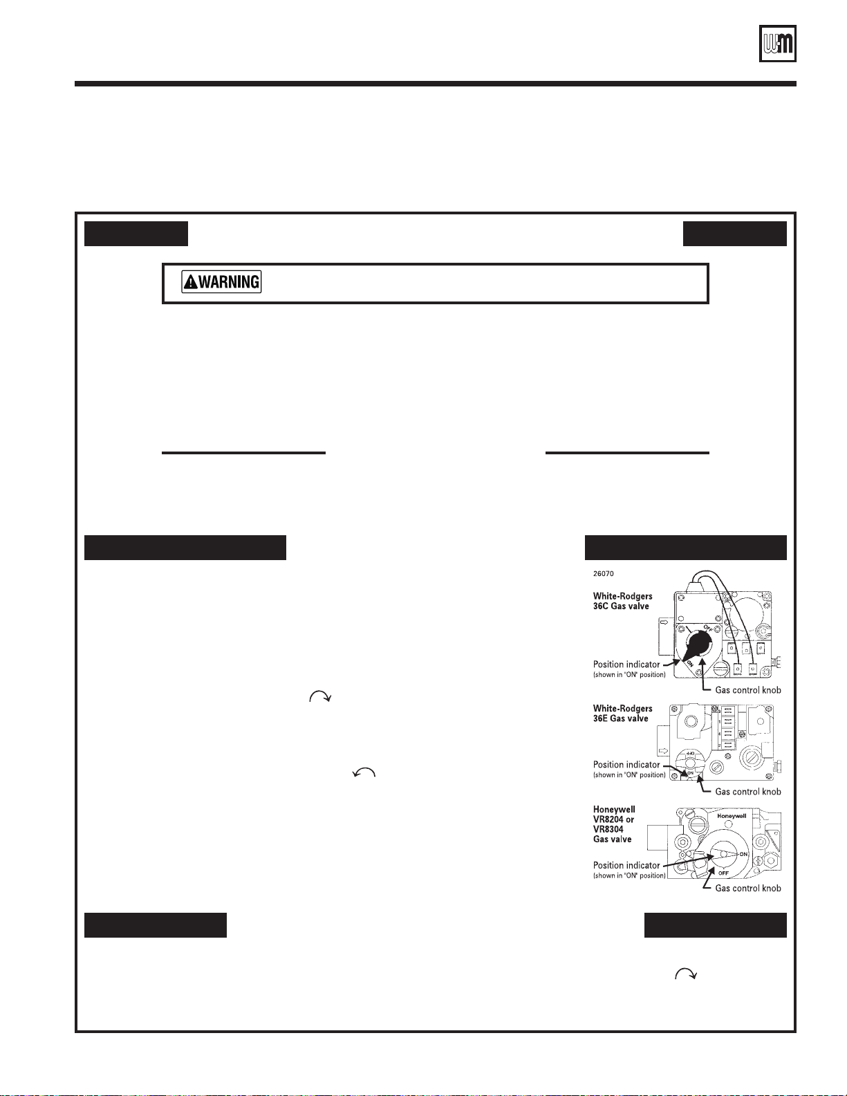
User’s Information Manual
Operating instructions
CGi, CGs
• Spark-ignited pilot
• Gas valve — Honeywell VR8204/VR8304, White-Rodgers 36C and 36E
FOR YOUR SAFETY READ BEFORE OPERATING
If you do not follow these instructions exactly, a fire or explosion may result
causing property damage, personal injury or loss of life.
A. This appliance does not have a pilot. It is equipped
with an ignition device which automatically lights
the burner. Do not try to light the burner by
hand.
B. BEFORE OPERATING, smell all around the
appliance area for gas. Be sure to smell next to the
floor because some gas is heavier than air and will
settle on the floor. See below.
WHAT TO DO IF YOU SMELL GAS
• Donottrytolightanyappliance.
• Donottouchanyelectricswitch;donotuseany
phone in your building.
C. Useonlyyourhandtoturnthegascontrolknob. Neveruse
tools. If the knob will not turn by hand, don’t try to repair it,
call a qualified service technician. Force or attempted repair
may result in a fire or explosion.
D. Do not use this appliance if any part has been under water.
Immediately call a qualified service technician to inspect the
appliance and to replace any part of the control system and any
gas control, which has been under water.
• Immediatelycallyourgassupplierfromaneighbor’sphone.
Follow the gas supplier’s instructions.
• If you cannot r each your g as sup pli er, call the f ire
department.
OPERATING INSTRUCTIONS
1. STOP ! Read the safety information above on this label.
2. Set the thermostat to lowest setting.
3. Turn off all electrical power to the appliance.
4. Remove jacket front panel.
5. This appliance is equipped with an ignition device which automatically lights the burner.
Do not try to light the burner by hand.
6. Turn
7. Wait five (5) minutes to clear out any gas. Then smell for gas, including near the floor.
8. Turn Gas control knob counterclockwise to “ON”.
9. Turn on all electric power to the appliance.
10. Set thermostat to desired setting.
11. If the appliance will not operate, follow the instructions “TO TURN OFF GAS TO
12. Replace jacket front panel.
Gas control knob clockwise to “OFF”.
If you smell gas,
gas, go to the next step.
APPLIANCE
STOP ! Follow “B” in the safety information above. If you don’t smell
” below and call your service technician or gas supplier.
TO TURN OFF GAS TO THE APPLIANCE
1. Set the thermostat to lowest setting.
2. Turn off all electric power to the appliance if service is to
be performed.
Part Number 550-110-592/0709
3. Remove jacket front panel.
4. Turn Gas control knob clockwise to “OFF”.
Do not force.
5. Replace jacket front panel.
21
Page 22
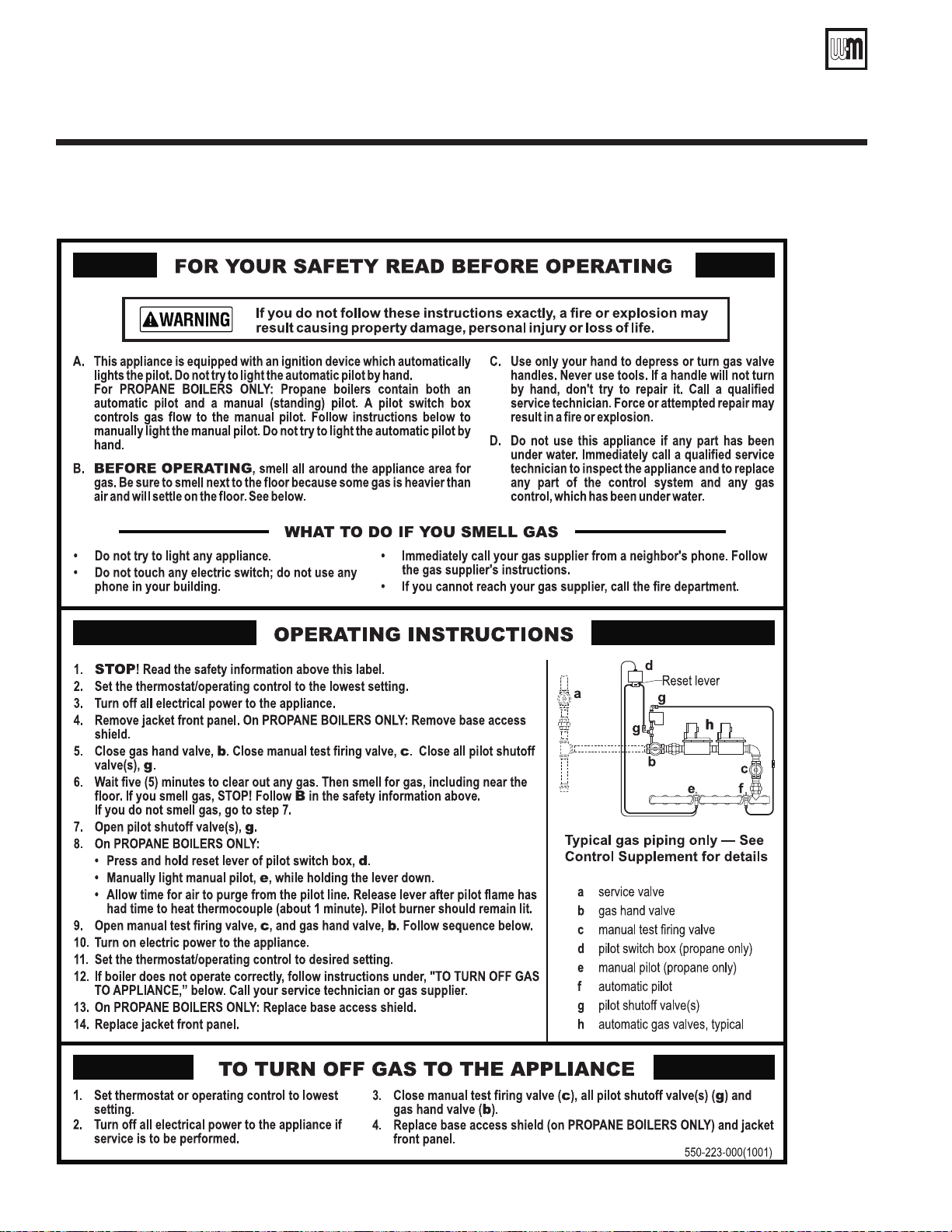
CGa, CGi, CGs, EG, EGH, LGB, PEG, PFG Boilers
Operating instructions
• Spark-ignited pilot
LGB
22
Part Number 550-110-592/0709
Page 23
User’s Information Manual
Symptom Common Causes Possible Corrections
Rapid cycling —
boiler turns on and
off frequently
Thermostat installed where drafts
or heat affect reading
Locate thermostat on inner wall away from heat sources or cool
drafts.
Heat anticipator in thermostat
adjusted incorrectly
Adjust thermostat per manufacturer's instructions.
Incorrect limit setting Set limit according to system needs. Maximum setting is 220˚F.
Increase limit setting to decrease cycling.
Insufficient water flow through
boiler
Check all valves to and from boiler. Return to proper setting.
Confirm circulator size.
Frequent release of
water through relief
valve
Expansion tank sized too small Call qualified service technician to check expansion tank
operation and size.
Flooded expansion tank Call qualified service technician to check expansion tank
operation.
Inoperative limit control Call qualified service technician to replace limit control.
Need to frequently
add makeup water
Leaks in boiler or piping Have qualified service technician repair leaks at once to avoid
constant use of makeup water. Makeup water can cause
mineral deposits which, in turn, can cause boiler section failure.
Do not use petroleum-base stop-leak compounds.
Black water
condition
Oxygen corrosion due to leaks in
boiler and piping
Have qualified service technician repair at once. Keep pH of
water between 7.0 to 8.5.
Popping or
percolating noise
heard in boiler
Mineral deposits in sections due
to constant use of makeup water
Call qualified service technician to de-lime boiler, if necessary.
In some cases, deposits will be too heavy to remove with deliming procedures.
Have qualified service technician repair leaks to eliminate need
for constant makeup water.
Incorrect pH of boiler water Call qualified service technician to check pH level and correct.
pH should be maintained between 7.0 to 8.5.
Insufficient water flow through
boiler
Check all valves to and from boiler. Return to proper setting.
Confirm circulator size.
Metal flakes found in
vent outlet or vent —
flueway corrosion
Contaminated combustion air
supply — See page 3 in this
manual.
Remove any contaminating products. See page 3 in this
manual.
Provide outside air for combustion. Kit available through WeilMcLain distributor. Have qualified service technician pipe-up kit.
Condensation of combustion
gases in boiler sections
Have qualified service technician inspect system piping and
controls to verify proper regulation of return water temperature.
Some radiators or
baseboard units do
not heat or are noisy
Air in system Bleed air from system through air vents in radiators or
baseboard units.
Low system pressure Fill to correct pressure.
Check for leaks in boiler or piping. Have qualified service
technician repair at once.
High limit set too low Adjust high limit to higher setting.
Common problems and solutions
Part Number 550-110-592/0709
23
Page 24

Weil-McLain
500 Blaine Street
Michigan City, IN 46360-2388
http://www.weil-mclain.com
24
Part No. 550-110-592/0709
 Loading...