

Weil-McLain 1194, 1294, 1094, 1394, 1494 Series Manual
...
94
Series 3
Water & steam boilers
for use with Gas, Light Oil, & Gas/Light Oil – Fired Burners
Boiler Manual
• Installation
• Startup
• Maintenance
• Parts
For additional
information, refer to . .
Burner specifi cation
and data sheets
(for burners pre-tested with
model 94 boilers)
This manual must only be used by a qualifi ed
heating installer/service technician. Read
all instructions before installing. Follow
all instructions in proper order. Failure
to comply could result in severe personal
injury, death or substantial property damage.
INSTALLER Consider piping and installation when determining
boiler location.
Any claims for damage or shortage in shipment must be
fi led immediately against the transportation company
by the consignee.
USER . . . . This manual is for use only by your qualifi ed heating
installer/service technician. Boiler and burner must be
installed by a qualifi ed service technician. We recommend regular service by a qualifi ed service technician,
at least annually.
Part No. 550-110-275/1018

Weil-McLain 94 Series 3 Water and steam boilers — for Gas, Light Oil, & Gas/Light Oil-Fired Burners
Read before proceeding
Read before proceeding:
Read all instructions before installing. Fail-
ure to follow all instructions in proper order
can cause severe personal injury, death or
substantial property damage.
Do not use petroleum-based cleaning or
sealing components in boiler system. Severe
damage to system components can result,
causing substantial property damage.
Propane boilers only — Your propane
supplier mixes an odorant with the propane
to make its presence detectable. In some
instances, the odorant can fade and the gas
may no longer have an odor.
■ Propane gas can accumulate at floor
level. Smell near the floor for the gas
odorant or any unusual odor. If you
suspect a leak, do not attempt to light
the burner.
■ Use caution when attempting to light a
propane burner (or pilot burner). This
should be done by a qualified service
technician, particularly if flame outages (or pilot outages) are common.
Hazard Definitions
The terms defined below are used throughout this manual
to bring attention to the presence of hazards of various
risk levels, or to important information concerning the
life of the product.
Indicates presence of hazards that will
cause severe personal injury, death or
substantial property damage if ignored.
Indicates presence of hazards that can
cause severe
substantial property damage if ignored.
Indicates presence of hazards that will or
can cause minor personal injury, death or
substantial property damage if ignored.
Indicates special instructions on installa-
tion, operation or maintenance that are important but not related to personal injury.
personal injury, death or
■ Periodically check the odorant level of
your gas.
■ Inspect boiler and system at least yearly
to make sure all gas piping is leak-tight.
■ Consult your propane supplier regarding installation of a gas leak detector.
There are some products on the market
intended for this purpose. Your supplier may be able to suggest an appropriate device.
Controls:
One limit control is supplied with the
boiler. A second limit control must be
supplied by the installer (field installed)
to comply with current ASME Boiler and
Pressure Vessel Code, Section IV.
IMPORTANT
When calling or writing about the boiler, please provide:
• Boiler model number
• Series
• CP number
This information is located on the boiler label/nameplate.
2 Part No. 550-110-275/1018

Boiler manual: • Installation • Start-Up • Maintenance • Parts
Contents
Before installing boiler . . . . . . . . . . . . . . . . . . . . . . . . . . . . . . . . . 4
Set boiler in place . . . . . . . . . . . . . . . . . . . . . . . . . . . . . . . . . . . . 7
Assembling the block . . . . . . . . . . . . . . . . . . . . . . . . . . . . . . . . . . 8
Perform hydrostatic pressure test . . . . . . . . . . . . . . . . . . . . . . . . . . . 11
Control tapping locations — water boilers . . . . . . . . . . . . . . . . . . . . . . 12
Control tapping locations — steam boilers . . . . . . . . . . . . . . . . . . . . . . 13
Connect water boiler piping . . . . . . . . . . . . . . . . . . . . . . . . . . . . . . 14
Connect steam boiler piping . . . . . . . . . . . . . . . . . . . . . . . . . . . . . . 16
Complete block assembly & install jacket . . . . . . . . . . . . . . . . . . . . . . . 20
Pipe tankless heaters . . . . . . . . . . . . . . . . . . . . . . . . . . . . . . . . . . 25
Install water boiler controls. . . . . . . . . . . . . . . . . . . . . . . . . . . . . . . 26
Install steam boiler controls . . . . . . . . . . . . . . . . . . . . . . . . . . . . . . 28
Connect breeching and venting systems . . . . . . . . . . . . . . . . . . . . . . . 31
Install fuel piping . . . . . . . . . . . . . . . . . . . . . . . . . . . . . . . . . . . . 34
Make final adjustments . . . . . . . . . . . . . . . . . . . . . . . . . . . . . . . . . 35
Handling ceramic fiber and fiberglass materials . . . . . . . . . . . . . . . . . . . 36
Maintenance and troubleshooting . . . . . . . . . . . . . . . . . . . . . . . . . . . 37
Ratings . . . . . . . . . . . . . . . . . . . . . . . . . . . . . . . . . . . . . . . . . . 41
Dimensions . . . . . . . . . . . . . . . . . . . . . . . . . . . . . . . . . . . . . . . 42
Parts . . . . . . . . . . . . . . . . . . . . . . . . . . . . . . . . . . . . . . . . . . . 44
3Part No. 550-110-275/1018
Weil-McLain 94 Series 3 Water and steam boilers — for Gas, Light Oil, & Gas/Light Oil-Fired Burners
Before installing boiler
Installation must comply with —
1. State, provincial and local plumbing, heating and electrical codes.
2. Regulations of servicing utilities.
3. ASME Section IV, Low Pressure Boiler and Pressure Vessel Code.
4. National Fuel Gas Code, ANSI/NFPA 54, when applicable.
5. National codes where applicable.
Before selecting boiler location
1. Check for nearby connections to:
a. Fuel supply.
b. Electrical power.
c. System water or steam piping.
d. Venting systems — see page 31.
e. Combustion and ventilation air supply — see page 5.
2. Check area around boiler. Remove any combustible materials, gasoline
and other flammable vapors and liquids.
Failure to keep boiler area clear and free of combustible
materials, gasoline and other flammable liquids and vapors
can result in severe personal injury, death and substantial
property damage.
Provide clearance around boiler
1. Provide minimum clearances to combustible materials:
• Boiler top — 24 inches.
• Boiler front — 48 inches.
•
Boiler flue — 9 inches.
• Boiler rear — 9 inches.
• Boiler sides — 6 inches.
• Single-wall vent pipe – 18 inches.
• Double-wall vent pipe – refer to vent pipe manufacturer's recom-
mendations for vent pipe clearances.
2. Boiler may be installed on combustible flooring.
3. See page 42 for boiler dimensions.
Flue pipe/breeching clearances take precedence over jacket
clearances. Follow local codes requirements for clearances.
Increase clearances if necessary.
4. Provide minimum clearances for servicing:
• Right side — for cleaning and for tankless heater insertion/re-
moval — 44 inches.
•
Rear — for breeching — 50 inches.
• Allow sufficient space on remaining sides for cleaning, servicing
and burner installation. See burner literature for length and recommended service clearances.
Lay a foundation, if needed
1. Floor construction and condition must be suitable for weight of boiler
when filled with water. See page 42 for approximate boiler operating
weight.
2. A level concrete or brick foundation, constructed per Figure 1 and
Figure 2 is required when:
a. A floor could possibly become flooded.
b. Non-level conditions exist.
c. Boiler must be raised for burner clearance.
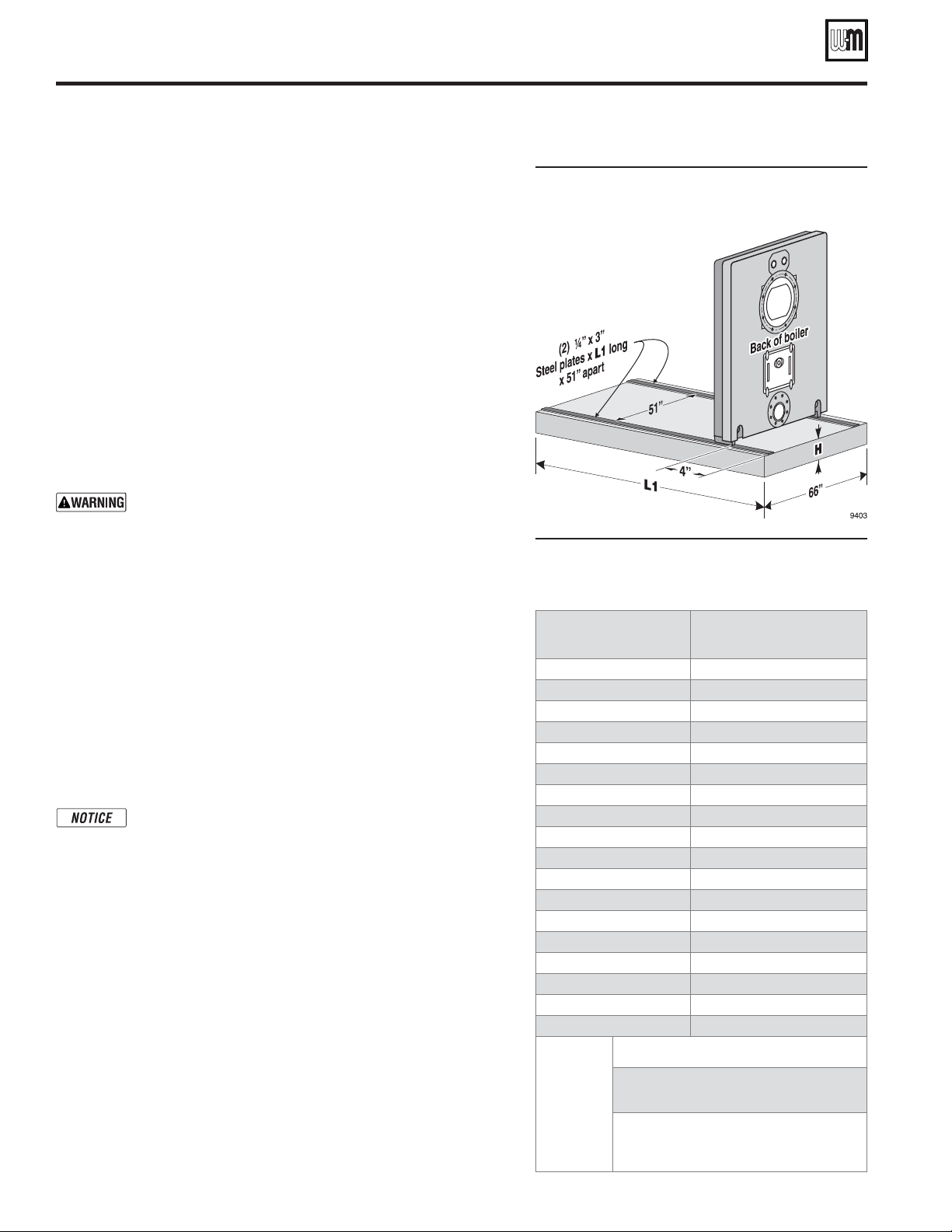
Figure 1 Boiler foundation, when required —
always use steel strips as shown for
proper draw-up and alignment of
sections
Figure 2 Boiler foundation (see Figure 1)
(boiler sections flush with one end of
foundation, 4 inches from the other
end)
Boiler model
number
894
994
1094
1194
1294
1394
1494
1594
1694
1794
1894
1994
2094
2194
2294
2394
2494
2594
Height,
H
(inches)
Gun-type burner: 2 inches min.
Horizontal rotary or air atomizing
burner: 7 inches min.
Consult burner manufacturer for
required clearances if burner is not
supplied by Weil-McLain.
Length,
(inches)
55
61
67
73
79
85
91
97
103
109
115
121
127
133
139
145
151
157
L1
4 Part No. 550-110-275/1018
Boiler manual: • Installation • Start-Up • Maintenance • Parts
Before installing boiler
(continued)
Combustion and ventilation air openings
Adequate combustion and ventilation air must be
provided to assure proper combustion and prevent
possibility of flue gas leakage and carbon monoxide
emissions, causing severe personal injury or death.
Do not install an exhaust fan in boiler room. Incor-
rect burner operation can result.
When combustion and ventilation air enters
through side wall openings, ensure that the openings comply with the requirements of Figure 3 and
Figure 4.
Opening sizes must comply with state, provincial or
local codes. In the absence of local requirements, use
the National Fuel Gas Code, ANSI/NFPA 54). The
following information is taken from ANSI/NFPA 54.
For details and information not addressed below,
refer to the standard.
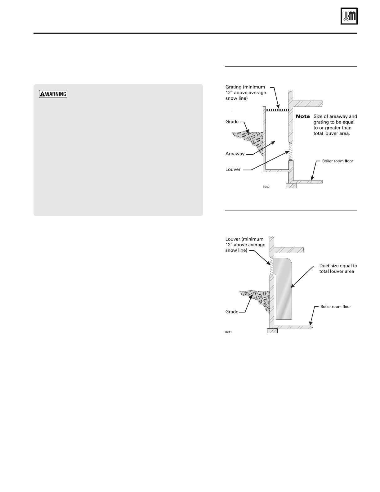
Figure 3 Combustion and ventilation air
openings — Boiler room below grade
Figure 4 Combustion and ventilation air
openings — Boiler room partially or
completely above grade
Combustion air openings to inside
Required volume of interior spaces
ANSI/NFPA 54 allows combustion air to be supplied through openings
to interior spaces if the volume of the connected interior spaces
meets the minimum volume required by the standard.
The minimum volume of interior spaces can be taken as 50 cubic feet
per 1,000 Btuh of all appliances in the spaces, or the minimum volume
can be calculated using the formulas given in ANSI/NFPA 54. Exception: If the air infiltration rate for the spaces is known to be less than
0.40 air changes per hour, the minimum volume must be calculated
as specified in the standard.
Inside air opening sizes and locations
For spaces that provide the minimum volume required by ANSI/
NFPA 54, the air openings must be sized per the following:
Combining spaces on the same story — Each opening shall have
a minimum free area of 1 in2 ⁄1000 Btuh (2200 mm2 /kW) of the total
input rating of all appliances in the space but not less than 100 in2
(0.06 m2). One opening shall commence within 12 inches (300 mm)
of the top, and one opening shall commence within 12 inches (300
mm) of the bottom, of the enclosure. The minimum dimension of air
openings shall be not less than 3 inches (80 mm).
Combining spaces in different stories — The volumes of spaces
in different stories shall be considered as communicating spaces where
such spaces are connected by one or more openings in doors or floors
having a total minimum free area of 2 in2 ⁄1000 Btuh (4400 mm2 /kW)
of total input rating of all appliances.
Combustion air openings to
outside
Outdoor combustion air can be taken through permanent openings (TWO or ONE), as described in the
following. The minimum dimension of air openings
shall not be less than 3 inches (80 mm).
Outside openings: TWO permanent openings
method
Two permanent openings, one commencing within
12 inches (300 mm) of the top and one commencing
within 12 inches (300 mm) of the bottom of the enclosure shall be provided. The openings shall communicate
directly, or by ducts, with the outdoors or spaces that
5Part No. 550-110-275/1018

Weil-McLain 94 Series 3 Water and steam boilers — for Gas, Light Oil, & Gas/Light Oil-Fired Burners
Before installing boiler
freely communicate with the outdoors, as follows:
• Where directly communicating with the outdoors or
where communicating to the outdoors through vertical
ducts, each opening shall have a minimum free area of
2
⁄4000 Btuh (550 mm2/kW) of total input rating of
1 in
all appliances in the enclosure.
• Where communicating with the outdoors through hori-
zontal ducts, each opening shall have a minimum free
area of 1 in
rating of all appliances in the enclosure.
Outside openings: ONE permanent opening method
One permanent opening, commencing within 12 inches
(300 mm) of the top of the enclosure, shall be provided. The
appliance shall have clearances of at least 1 in. (25 mm) from
the sides and back and 6 inches (150 mm) from the front of the
appliance. The opening shall directly communicate with the
outdoors or shall communicate through a vertical or horizontal
duct to the outdoors or spaces that freely communicate with the
outdoors and shall have a minimum free area of the following:
2
(1) 1 in
of all appliances located in the enclosure, and . . .
(2) Not less than the sum of the areas of all vent connectors in
the space.
⁄3000 Btu/hr (700 mm2 per kW) of the total input rating
2
⁄2000Btuh (1100 mm2 /kW) of total input
(continued)
Combustion air — combination indoor
and outdoor openings
ANSI/NFPA 54 allows combustion air to be taken from a combination of openings to outside and to interior spaces. Follow all
requirements of the standard to determine the minimum volume
of interior spaces and to calculate minimum sizes of openings.
Mechanical Combustion Air Supply
Where all combustion air is provided by a mechanical air supply
system, the combustion air shall be supplied from outdoors at
the minimum rate of 0.35 ft3/minute per 1000 Btuh (0.034 m3/
min per kW) for all appliances located within the space.
• Where exhaust fans are installed in the building, additional air shall be provided to replace the exhausted air.
• Each of the appliances served shall be interlocked to the
mechanical air supply system to prevent main burner
operation where the mechanical air supply system is not
in operation.
• Where combustion air is provided by the building’s mechanical ventilation system, the system shall provide the
specified combustion air rate in addition to the required
ventilation air.
Louvers, Grilles, and Screens.
The required size of openings for combustion, ventilation, and
dilution air shall be based on the net free area of each opening.
Where the free area through a design of louver or grille or screen
is known, it shall be used in calculating the size opening required
to provide the free area specified.
Where the louver and grille design and free area are not known,
it shall be assumed that wood louvers will have 25 percent free
area, and metal louvers and grilles will have 75 percent free area.
Non-motorized louvers and grilles shall be fixed in the open
position.
Minimum screen mesh size
Screens shall not be smaller than ¼ inch mesh.
Motorized louvers
Motorized louvers shall be interlocked with the appliance so they
Engineered Installations
Engineered combustion air installations shall provide an adequate supply of combustion, ventilation, and dilution air and
shall be approved by the authority having jurisdiction.
6 Part No. 550-110-275/1018
are proven in the full open position prior to main burner ignition
and during main burner operation. Means shall be proved to
prevent the main burner from igniting should the louver fail to
open during burner startup, and to shut down the main burner
if the louvers close during burner operation.

Boiler manual: • Installation • Start-Up • Maintenance • Parts
Set boiler in place
Ensure the equipment and cables used for lifting are
designed to handle the load. See Figure 5 for approximate
weights of model 94 section assemblies. Failure to comply
can result in severe personal injury, death or substantial
property damage.
The boiler contains ceramic fiber and fiberglass materials.
Use care when handling these materials per instructions
on "Handling ceramic fiber and fiberglass materials,"
page 36 of this manual. Failure to comply could result
in severe personal injury.
For packaged boiler or assembled block
assembly:
1. Packaged boilers only — Remove top jacket panels. Set aside until
after boiler is piped.
2. Remove lag screws from shipping rails.
3. Remove boiler from skid. Cables are already attached to block assembly. See Figure 5 for lifting weight.
• Using crane – attach free end of cables to eye of crane.
• Using hoist – attach free end of cables to hoist. Raise boiler
off skid. Use pipe rollers under steel skid angles to roll boiler.
4. Place ¼" x 3" steel plates on floor or foundation, spaced 51 inches
apart, as shown in Figure 1, page 4.
5. Place boiler in final position. Place boiler on foundation (if used)
as shown in Figure 1, page 4.
6. Level boiler. Shim under legs if necessary.
7. Cut off cables.
Cables are not intended for long-term usage. Cables may
corrode inside boiler, weakening their lifting strength.
Failure to remove cables can result in severe personal
injury, death or substantial property damage.
8. Inspect block assembly for disjointed sections.
a. Check inside section assembly for any light passing through
unsealed areas.
b. Mark all unsealed areas.
c. At unsealed areas, check for:
• Damaged gaskets.
• Sealing rope not in place.
• Loose bolts or nuts.
d. Correct all conditions and repeat step b. If unsealed areas still
exist, contact your Weil-McLain distributor or sales office
before continuing installation.
9. Check gas-tight seal of flue collector hood and cleanout plates.
Do not raise or move assembled sections
using a jack or forklift. This could cause
the sections to shift, resulting in leaks.
Figure 5
Section assembly lifting weights
Boiler
model
number
894 8600
994 9500
1094 10300
1194 11200
1294 12000
1394 12800
1494 13700
1594 14500
1694 15400
1794 16200
1894 17100
1994 17900
2094 18700
2194 19800
2294 20600
2394 21500
Approximate
lifting
weight
(pounds)
Minimum
sling length —
(from crane hook to
boiler lifting lugs)
3' 6"
3' 6"
4' 0"
4' 6"
5' 0"
5' 0"
5' 0"
5' 0"
5' 0"
5' 0"
5' 0"
5' 6"
5' 6"
7' 6"
7' 6"
7' 6"
Gas tight seal must be maintained to prevent possible flue
gas leakage and carbon monoxide emissions, resulting
in severe personal injury or death.
10. Proceed to "Perform hydrostatic pressure test," page 11.
2494 22400
2594 23200
8' 0"
8' 0"
7Part No. 550-110-275/1018

Weil-McLain 94 Series 3 Water and steam boilers — for Gas, Light Oil, & Gas/Light Oil-Fired Burners
Assembling the block
Sections are top heavy. Unbolted sections may fall if not
supported, resulting in severe personal injury or death.
Prepare the back section first
1. Place ¼" x 3" steel plates on the floor or foundation, spaced 51 inches
apart, as shown in Figure 1, page 4.
2. Apply
1
⁄8" continuous bead of sealing rope adhesive in sealing rope
grooves around section perimeter and around flueways — see Figure 6.
Do not get any adhesive on the machined port surfaces.
Place sealing rope in grooves
1. Place 5⁄8" coated and uncoated sealing rope in the rope grooves as shown
in Figure 6.
2. See WARNING below — place coated rope and uncoated rope as
described.
3. Around curves, grasp rope at 1" intervals and push together.
stretch the rope
.
Do not
Figure 6 Sealing rope installation
The boiler is supplied with TWO types of section sealing
rope — uncoated and coated with a narrow uncoated strip.
Use the uncoated rope only on the flueways as shown in
Figure 6.
Use the coated rope around the perimeter and around the
upper nipple port as shown in Figure 6. The uncoated side
of the rope must be pressed into the adhesive as shown in
order to obtain a proper adhesion.
DO NOT pre-cut rope for sections. Cut rope as each section
is placed.
A gas-tight seal must be maintained to prevent possibility
of flue gas leakage and carbon monoxide emissions, causing
severe personal injury or death.
Do not use petroleum-based cleaning or sealing com-
pounds in boiler system. Severe damage to system components can result, causing substantial property damage.
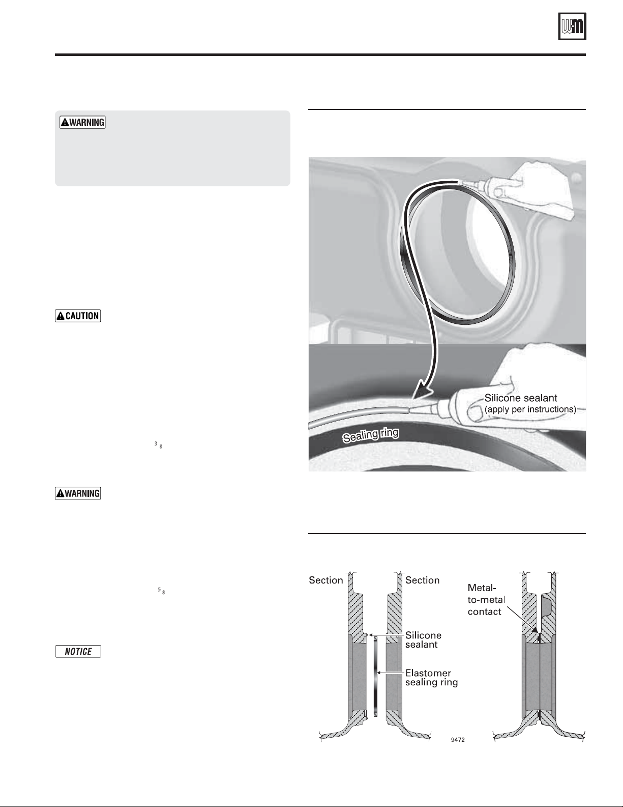
Install nipple port sealing rings
1. Remove any grit from port machined surfaces with clean rag.
2. Place 9" and 6" sealing rings in appropriate port openings as shown in
Figure 6, page 8. If sealing ring slips out of groove, stretch ring gently
for several seconds, then reposition in groove.
3. Apply a continuous bead of silicone sealant no larger than
entire outside edge of the outer machined surface of the port. See Figure 7. Do not apply silicone sealant on, next to or under sealing ring.
1
⁄16" around
8 Part No. 550-110-275/1018
Boiler manual: • Installation • Start-Up • Maintenance • Parts
Assembling the block
Silicone sealant applied as specified above
prevents unburned oil vapors from coming
in contact with sealing ring. Vapor contact can damage rings, resulting in severe
damage to boiler and substantial property
damage.
Raise the rear section upright
1. Hoist the back section upright.
2. Move rear section into position on the steel rails. The
section should be 4 inches from the end of the foundation (if used) as shown in Figure 1, page 4.
3. Block under the flueway outlet to hold the rear section
upright in plumb position.
The back section must be plumb before in-
stalling other sections to ensure the block will
assemble correctly.
4. The blocking under the flueway can be removed later,
after several intermediate sections have been attached
and the assembly is stable.
5. Install intermediate sections and front section as described on the following.
(continued)
Figure 7 Applying silicone sealant around outsides of sealing
rings (shown on 94 intermediate section upper nipple
port)
Install intermediate sections
1. Remove and discard 3⁄8" diameter shipping tie rods.
2. Remove grit from port machined surfaces with clean
rag. Also remove grit from tapped holes in all sections.
Do not use petroleum-based cleaning or
sealing compounds in boiler system. Severe
damage to system components can result,
causing substantial property damage.
3. Position intermediate section so aligning lugs fit into
sockets of next section. See Figure 8.
4. Draw sections together until metal-to-metal contact is
made around machined port openings (see Figure 8):
a. Oil threads on (4)
and nut on end to be tightened. Use nut only on
other end.
b. Uniformly draw sections together, starting at
washer/nut end.
Important — Leave an equal amount of thread
on each end of the draw rod. This is needed
to allow securing the jacket support brackets
in place. The draw rods must not extend past
the face of the front or back section, or they
will interfere with the jacket.
c. Draw rods should be torqued to a range of 100 to
120 ft-lbs. Do not back off draw rods.
d. Metal-to-metal contact will be achieved around port
openings. See Figure 8. If gap occurs, it should be no
greater than .032". Check with feeler gauge.
5
⁄8" x 11" draw rods. Install washer
Figure 8 Sealing ring installation and port alignment, typical
Weil-McLain cast iron section nipple port
9Part No. 550-110-275/1018

Weil-McLain 94 Series 3 Water and steam boilers — for Gas, Light Oil, & Gas/Light Oil-Fired Burners
Assembling the block
e. If, for any reason, the gap around machined port open-
ing exceeds .032", check for rope extending from rope
(continued)
6. Check each section for proper sealing rope position before
proceeding to next section.
grooves, dirt on port openings or sockets, or misaligned
lugs. If corrections are made and gap still exists, contact
your Weil-McLain distributor or sales office before continuing installation.
Failure to position sealing rope properly can
cause boiler to not seal gas-tight. Gas tight seal
prevents possible flue gas leakage and carbon
monoxide emissions, resulting in severe personal
After erecting first intermediate section, check
injury or death.
both sections for plumb. Repeat the check as each
additional section is installed. Failure to plumb sections can cause misaligned piping and breeching,
7. Install remaining intermediate sections and front section
using the same procedure.
possibly resulting in property damage.
5. Repeat steps 1-5 for all remaining sections. NOTE — use
x 10" draw rods between intermediates. When used, install TI
(tankless intermediate) and SI (supply intermediate) sections
in the positions shown in Figure 9, page 10.
5
If using tankless heater (TI) sections
⁄8"
• Install tankless heaters and gaskets or heater cover plates
and gaskets.
3
• Use
⁄8" x 3⁄4"studs, washers and nuts.
Figure 9 Section arrangement (location of TI and SI sections, numbered from REAR to FRONT of block assembly)
Boiler
W = water
S = steam
# of coils ——
894 W or S 5 5, 7 3, 5, 7 — — — — — —
994 W or S 6 6, 8 2, 4, 6 2, 4, 6, 8 — — — — —
1094 W or S 4 2, 4 2, 4, 7 2, 4, 7, 9 — — — — —
1194 W or S 4 2, 4 2, 4, 8 2, 4, 8, 10 — — — — —
1294 W or S 4 2, 4 2, 4, 9 2, 4, 9, 11 2, 4, 7, 9, 11 — — — —
1394 W or S 5 3, 5 3, 5, 10 3, 5, 10, 12 3, 5, 8, 10, 12 — — — —
1494 W or S 6 4, 6 2, 4, 6 4, 6, 11, 13 2, 4, 6, 11, 13 2, 4, 6, 9, 11, 13 — — —
1594 W or S 6 4, 6 2, 4, 6 4, 6, 12, 14 2, 4, 6, 12, 14 2, 4, 6, 10, 12, 14 — — —
1694 W or S 6 4, 6 2, 4, 6 4, 6, 13, 15 2, 4, 6, 13, 15 2, 4, 6, 9, 11, 13 2, 4, 6, 9, 11, 13, 15 — —
1794 W or S 7 5, 7 3, 5, 7 5, 7, 14, 16 3, 5, 7, 14, 16 3, 5, 7, 10, 12, 14 3, 5, 7, 10, 12, 14, 16 — —
1894 W or S 8 6, 8 2, 4, 6 2, 4, 6, 8 2, 4, 6, 8, 15 2, 4, 6, 8, 15, 17 2, 4, 6, 8, 11, 13, 15 2, 4, 6, 8, 11, 13, 15, 17 —
1994 W or S 6 4, 6 2, 4, 6 4, 6, 9, 11 2, 4, 6, 9, 11 2, 4, 6, 9, 11, 16 2, 4, 6, 9, 11, 16, 18 2, 4, 6, 9, 11, 14, 16, 18 —
2094 W or S 6 4, 6 2, 4, 6 4, 6, 10, 12 2, 4, 6, 10, 12 2, 4, 6, 10, 12, 17 2, 4, 6, 10, 12, 17, 19 2, 4, 6, 10, 12, 15, 17, 19 —
If the boiler was ordered with tankless coils, the heaters must be located on the right hand side of the boiler. It is important to position the TI
sections (where used) in the exact location in the boiler section assembly as shown above so the heater knockout openings in the jacket side
panels will accommodate the heaters. If the TI sections and internal water heaters are not positioned in the boiler section assembly as shown
above, the installer must cut openings in the jacket side panels to accommodate the heaters.
>
12 3 4 5 6 7 8
2194 W 6 4, 6 2, 4, 6 2, 4, 6, 9 2, 4, 6, 9, 11 2, 4, 6, 9, 11, 13 2, 4, 6, 9, 11, 13, 16 — 18, 20
2294 W 6 4, 6 2, 4, 6 2, 4, 6, 10 2, 4, 6, 10, 12 2, 4, 6, 10, 12, 14 2, 4, 6, 10, 12, 14, 17 — 19, 21
2394 W 6 4, 6 2, 4, 6 2, 4, 6, 9 2, 4, 6, 9, 11 2, 4, 6, 9, 11, 13 2, 4, 6, 9, 11, 13, 15 2, 4, 6, 9, 11, 13, 15, 18 20, 22
2494 W 8 6, 8 2, 4, 6 2, 4, 6, 8 2, 4, 6, 8, 12 2, 4, 6, 8, 12, 14 2, 4, 6, 8, 12, 14, 16 2, 4, 6, 8, 12, 14, 16, 19 21, 23
2594 W 8 6, 8 2, 4, 6 2, 4, 6, 8 2, 4, 6, 8, 11 2, 4, 6, 8, 11, 13 2, 4, 6, 8, 11, 13, 15 2, 4, 6, 8, 11, 13, 15, 17 22, 24
2194 S 2 2, 9 2, 9, 11 2, 9, 11, 13 2, 9, 11, 13, 20 — — — 4, 6, 16, 18
2294 S 2 2, 10 2, 10, 12 2, 10, 12, 14 2, 10, 12, 14, 21 — — — 4, 6, 17, 19
2394 S 2 2, 9 2, 9, 11 2, 9, 11, 13 2, 9, 11, 13, 15 2, 9, 11, 13, 15, 22 — — 4, 6, 18, 20
2494 S 8 2, 8 2, 8, 12 2, 8, 12, 14 2, 8, 12, 14, 16 2, 8, 12, 14, 16, 23 — — 4, 6, 19, 21
2594 S 8 2, 8 2, 8, 11 2, 8, 11, 13 2, 8, 11, 13, 15 2, 8, 11, 13, 15, 17 2, 8, 11, 13, 15, 17, 24 — 4, 6, 20, 22
[numbering from REAR to FRONT, beginning with rear section as section number 1]
Placement of special intermediate sections (TI and SI)
TI sections
with tankless coil openings
SI sections
with supply
tappings
10 Part No. 550-110-275/1018

Boiler manual: • Installation • Start-Up • Maintenance • Parts
Perform hydrostatic pressure test
Install boiler connections
894 – 1294 W
1. Secure supply elbow and gasket to front section and supply
outlet cover plate and gasket to back section.
• Use
• Thread flat end of stud into section.
2. Secure 6" NPT return opening counter flange and gasket to
back section using ¾" x 2" cap screws and washers.
1394 – 2094 W
1. Secure supply elbow and gasket to front section.
2. Use
3. Thread flat end of stud into section.
4. Secure supply outlet cover plate and gasket to back section.
5. Use
6. Secure 8" pipe with standard 8" flange (not furnished) and
gasket (furnished) to back section. Use ¾" x 2" cap screws
and washers (furnished).
2194 — 2594 W
1. Secure outlet cover plate with 3 holes (¾" tapping on top)
and gasket to front section.
2. Secure outlet cover plate with 2 holes and gasket to back
section.
3. Use
4. Secure 10" supply outlets and gaskets on top of "SI" sections.
• Supply outlet should have 1¼" tapping facing front.
• Use
5. Secure 10" flanged return adapter and gasket to back section
using ¾" x 2" hex head cap screws and washers.
894 S
1. Secure supply elbow and outlet gasket to front section and
supply outlet cover plate and gasket to back section.
• Use
2. Secure 6" return opening counter flange and gasket to back
section. Use ¾" x 2" cap screws and washers.
994 — 2094 S
1. Secure supply elbows and outlet gaskets to front and back
sections.
• Use
• Thread flat end of stud into section.
2. Secure 6" NPT return opening counter flange and gasket to
back section. Use ¾" x 2" cap screws and washers.
2194 — 2594 S
1. Secure outlet cover plates and gaskets to front and back
sections.
• The ¾" tappings in plates should be at top.
• Use
5
⁄8" x 3" studs, nuts, and washers.
5
⁄8" x 3" studs, nuts, and washers.
5
⁄8" x 1¾" bolts.
5
⁄8" x 1¾" bolts.
5
⁄8" x 3" studs, nuts, and washers.
5
⁄8" x 1¾" bolts.
5
⁄8" x 3" studs, nuts and washers.
5
⁄8" x 1¾" bolts.
2. Secure 10" supply outlets and gaskets on top of "SI" sections.
• Supply outlet installed close to boiler front should have
1¼" tapping facing front.
• Use
5
⁄8" x 3" studs, nuts, and washers.
3. Secure 6" NPT return opening counter flange and gasket to
back section using ¾" x 2" hex head cap screws and washers.
Prepare boiler and test:
1. See Figure 10 (water boilers) or Figure 11 (steam boilers) for
tapping locations.
2. Install water pressure gauge —
can handle test pressure — see step 8 for required test pressure. Gauge range should be at least 1.5 times the test pressure. Install the pressure test gauge in the tapping specified
in Figure 10 (water boilers) or Figure 11 (steam boilers).
3. Install an air vent in an upper tapping.
4. On front section: Install 3" close nipples and caps in washout
tappings.
5. On rear section: Install drain valve (furnished by installer)
in one of the washout tappings. (Verify drain valve size per
Figure 15, page 15.) Install 2" x 2
other washout tapping.
6. Plug or use blind flanges on remaining tappings.
Do not pressure test with any control installed.
Damage to control can occur due to overpressure.
7. Fill the boiler with water. Vent all air.
8. Pressure test at least 10 minutes at a pressure not less than
the following:
a.
Steam boiler: Between 45 and 55 psig.
b.
Water boiler: 1½ times maximum allowable working
pressure
(MAWP) stamped on the boiler nameplate,
located on boiler jacket front panel.
Do not exceed above test pressures by more than
10 psig.
Do not leave boiler unattended. Cold water fill
could expand and cause excessive pressure, resulting in severe personal injury, death or substantial
property damage.
9. Check for maintained gauge pressure and leaks. Repair if
found.
Leaks must be repaired at once. Failure to do so
can damage boiler, resulting in substantial property
damage.
Do not use petroleum-based cleaning or sealing
compounds in boiler system. Severe damage to
system components can result, causing substantial
property damage.
10. Drain boiler and remove air vent, boiler drain and gauge.
11. Remove plugs from tappings that will be used for controls
and accessories.
for test only. Be sure gauge
1
⁄2" nipple and cap in the
11Part No. 550-110-275/1018

Weil-McLain 94 Series 3 Water and steam boilers — for Gas, Light Oil, & Gas/Light Oil-Fired Burners
Control tapping locations — water boilers
Figure 10 Model 94 water boiler control tappings
Item # Function Size
(Inches
NPT)
PRESSURE TEST GAUGE — REMOVE AFTER
J1
HYDROSTATIC TEST
J1 Temperature control or limit
J2 & J5
M3 Probe-type low water cutoff
M1 + M2
M3 + M4
P1 or R1 Temperature control or limit
S1 P/T gauge or temperature gauge
T1 or T2
U1 & U2
V1 Temperature control or limit
PLUG these tappings — not used on water boilers
Float-type low water cutoff or LWCO/feeder
combination
Temperature control or limit — or —
Air vent piping to compression tank
Pressure relief valve(s):
894–2094: Install relief valve in one tapping and plug
the other tapping
2194–2594: Install a relief valve in each tapping
(2 relief valves required on these boilers)
1¼
½
½
½
1
1
3
¾
2
4
W1 or W2
X1 or X2
Y1 & Y2
Z1 or Z2
Z3 or Z4
—
Temperature control or limit — or —
P/T gauge or temperature gauge
Temperature control or limit — or —
Air vent piping to compression tank
PLUG this tapping — unless needed for a control
Cleanout tappings — Front section — Install 2" NPT
close nipple and 2" NPT cap in each cleanout tapping
Cleanout or drain tappings — Rear section —
Install drain valve in one tapping; install 2" NPT x 2½"
length nipple and 2" NPT cap in the other
Low limit control (when using tankless heaters) —
locate in control tapping on one of the tankless heaters
Controls and fi ttings must not
obstruct cleanout openings or
prevent required access to the
boiler or components.
1¼
¾
3
⁄8
2
2
—
12 Part No. 550-110-275/1018

Boiler manual: • Installation • Start-Up • Maintenance • Parts
Control tapping locations — steam boilers
Figure 11 Model 94 steam boiler control tappings
Item # Function Size
PRESSURE TEST GAUGE — REMOVE AFTER
J1
HYDROSTATIC TEST
J1 + J5
M3
M1 + M2
M3 + M4
P1 Skim tapping
P2 Steam pressure relief valve
R1 Skim tapping
R2 Steam pressure relief valve
S1
S2 Pressure controls (limit, operating, etc.)
T1 or T2 Pressure controls (limit, operating, etc.)
T3 or T4
U1 or U2
V1 or V2
W1 or W2
W3 or W4 Pressure controls (limit, operating, etc.)
X1 & X2
X3 & X4
Y1 & Y2 Try cocks
Z1 or Z2
Z3 or Z4
Gauge glass
J2
PLUG this tapping — not used
PLUG this tapping — not used
Float-type low water cutoff, LWCO/pump control or
LWCO/feeder combination
Steam pressure gauge — or —
Pressure controls (limit, operating, etc.)
Steam pressure gauge — or —
Pressure controls (limit, operating, etc.)
Steam pressure relief valve — Install relief valve in
one tapping and plug the other
Steam pressure relief valve — or —
Skim tapping
Steam pressure gauge — or —
Pressure controls (limit, operating, etc.)
PLUG these tappings — not used
PLUG these tappings — not used
Cleanout tappings — Front section — Install 2" NPT
close nipple and 2" NPT cap in each cleanout tapping
Cleanout or drain tappings — Rear section —
Install drain valve in one tapping; install 2" NPT x 2½"
length nipple and 2" NPT cap in the other
Low limit temperature control (when using tankless
—
heaters) — locate in control tapping on one of the tankless
heaters
(Inches
NPT)
½
½
½
1
1
3
3
4
4
¾
¾
1¼
1¼
2
4
¾
¾
1¼
1¼
3
⁄8
2
2
—
Controls and fi ttings must not
obstruct cleanout openings or
prevent required access to the
boiler or components.
13Part No. 550-110-275/1018

Weil-McLain 94 Series 3 Water and steam boilers — for Gas, Light Oil, & Gas/Light Oil-Fired Burners
Connect water boiler piping
General water piping information
1. System water supply and return piping should be installed and
piping connections attached to boiler before erecting jacket or
installing controls.
2. Do not pipe in through supply and out through return. This creates
reverse water flow through boiler that must not be used.
3. When installing in a system in which return water temperature can
drop below 140°F, apply the by-pass piping with by-pass pump as
shown in Figure 16, page 15.
4. When three-way valves are used for temperature modulation,
install slow-opening valves to minimize the potential of boiler
thermal shock.
Install piping
Install piping as shown in Figure 12, page 14 and Figure 16, page 15
(if applicable) for single boilers. For multiple boilers, see Figure 17, page 15.
Improperly piped systems or undersized piping can
contribute to erratic boiler operation and possible boiler
or system damage.
1. Connect supply and return piping:
a. Size according to tables below.
• For
• For
known flow rates or higher flow rate (less than 20°F
temperature rise) through boiler, see Figure 13.
unknown flow rates, size piping per Figure 15, page 15,
using 20°F temperature rise through boiler.
Figure 12 Water boiler piping, typical
Flow at higher rates than shown in the tables in this
manual for given pipe sizes can damage the boiler, causing substantial property damage.
b. Locate circulator in supply piping.
c. For return piping, use full diameter pipe for 10 times that
diameter before making any reduction. For example, a 4-inch
return should not be reduced any closer to boiler return tapping than 40 inches.
d. Install system blow-off (drain) valve in lowest part of return
piping close to boiler. ASME minimum size requirements are
given in Figure 15, page 15.
2. Install expansion tank:
a.
Closed type – connect to 1
1
⁄4" tapping T1, T2 or X2 (see
Figure 10, page 12). Use 1" NPT piping. Any horizontal piping must pitch up toward tank at least 1 inch per each 5 feet
of piping.
b.
Diaphragm type – Refer to tank manufacturer's literature for
location. Install automatic air vent in 1
1
⁄4" tapping T1, T2 or
X2 (see Figure 10, page 12).
c. Connect cold water fill to expansion tank piping. Figure 12
shows typical piping when using a closed type tank. Connect
to the same location as the expansion tank connects to the
system when using a diaphragm type tank.
d. Also shown are recommended valves and water meter, when
used. Water meter will detect added make-up water, indicating
leaks in system.
Figure 13 Recommended minimum pipe sizes for
known flow rates
Water flow
rate, GPM
up to 77
78 – 132
133 – 208
209 – 300
301 – 520
521 – 820
Note 1 High temperature rise through boiler is per missible when boiler
Supply pipe sizeAReturn pipe size
3" 3"
4" 4"
5" 5"
6" 6"
8" 8"
10" 10"
piping connections are sized per this table.
Intermittent flow at high velocities may damage any
boiler.
(note 1)
B
14 Part No. 550-110-275/1018

Boiler manual: • Installation • Start-Up • Maintenance • Parts
Connect water boiler piping
Figure 14 Recommended minimum pipe sizes when flow rate is
994 – 1294
1394 – 2094
2194 – 2594
Note 1 Pipe sizes are based on a 20°F temperature rise through the boiler. For
Figure 15 ASME drain valve size
not known (see Figure 12, page 14)
Boiler
model
894
applications with higher flow rates (lower temperature rise), determine
the flow rate and use Figure 13, page 14 to size the piping. DO NOT
use flow rates in excess of 520 GPM through 894–2094 or 820 GPM
through 2194–2594.
Boiler
model
894 – 994
1094 – 2194
2294 – 2594
Supply pipe size
A
5" 5"
6" 6"
8" 8"
10" 10"
Minimum drain/blow-off
(note 1)
Return pipe size
B
valve size
1¼"
1½"
2"
(continued)
Figure 16 By-pass piping for return water less
than 140°F
By-pass circulator sizing:
1. Size system circulator as required. Determine GPM
and head requirements.
2. Provide a by-pass circulator for EACH boiler. The flow
rate for each by-pass circulator will be:
Flow = ¼ x (System circulator GPM) ÷ (# of boilers)
3. All circulators must run at the same time.
4. Example: For a 1,000,000 Btuh single boiler, with
system temperature drop of 20°F:
• System GPM = 1,000,000 ÷ 20 ÷ 500 = 100 GPM
• By-pass GPM = ¼ x 100 GPM = 25 GPM
• Determine by-pass circuit head loss for pipe size
and fittings used.
5. In most applications, a standard booster pump should
be adequate.
Piping multiple boilers
1. See Figure 16. (Expansion tanks, relief valves and other accessories
are required, but omitted from the illustration for simplicity.)
2. The boiler piping circuits are referred to as the secondary circuits
in the following.
3. The legend for Figure 16 and boiler pump sizing recommendations follow:
A Size boiler pump GPM based on the following:
a. Temp rise = High limit temp – Return water temp
b. GPM =
c. Calculate only secondary (boiler) piping circuit resistance. Al-
low for head loss through the boiler equal to three 90 degree
elbows of secondary pipe size.
d. Operate each boiler and its pump with a Weil-McLain boiler
control panel.
e. Size secondary (boiler) circuit piping using the flow rate ranges
given in Figure 15.
B Primary pump GPM and head calculation should not include
secondary boiler circuits. Primary pump can operate continuously
during heating season.
C Connection to primary circuit — Space 12" maximum or as close
as practical.
D Check valve.
E Hand valve.
Boiler Gross Output, Btuh
Temperature rise x 500
Figure 17 Multiple water boiler piping
15Part No. 550-110-275/1018
 Loading...