

Page 1

维 宏 股 份 创 业 板 :
3 0 0 5 0 8
NcStudio V10 CCD System
Quick Start
SPECIAL IZED CO NCEN TR ATED FOCUSED
Page 2

Table of Content
Getting Started............................................................................................................................................. 3
Wiring and IO Configuration ................................................................................................................. 4
Installing the Camera ................................................................................................................................ 6
Dimension of the Camera and Lens .......................................................................................... 6
Connecting the Camera .................................................................................................................. 8
Installing Software of the Camera ............................................................................................. 9
CCD Commissioning ............................................................................................................................... 12
Setting CCD Related Parameters ............................................................................................. 12
Setting CCD Working Plane ....................................................................................................... 15
Setting CCD Magnification Factor ........................................................................................... 16
Setting CCD-spindle Offset ......................................................................................................... 18
Picking Template ........................................................................................................................... 19
Setting Machining Attributes ................................................................................................... 21
Measuring Distance and Angles .............................................................................................. 22
Preparing Toolpath ................................................................................................................................ 22
Retrieving Contour from JPG File ........................................................................................... 22
Related Parameters ............................................................................................................ 23
Editing Toolpath ............................................................................................................................ 28
Setting Layer and Parameters ........................................................................................ 36
Convert DXF File to Toolpath ................................................................................................... 36
Running the Toolpath ............................................................................................................................ 39
FAQs .............................................................................................................................................................. 40
How to set aperture of the camera lens? ............................................................................. 40
What’s the relationship among the focal length, aperture and working distance?
............................................................................................................................................................... 40
Should I use two templates or three templates when getting marking points? 41
Page 3

Glossary ....................................................................................................................................................... 42
Page 4

Getting Started
WEIHONG ELECTRONIC TECHNOLOGY CO., LTD.
- 1 -
NcStudio V10 CCD System is another high-end control system that is exclusively
developed and copyrighted by WEIHONG Company. By taking photos in a real-time
manner, the control system can recognize marking points or templates and
automatically calculate deviations to make corrections to toolpath.
This document guides you how to get started with NcStudio V10 CCD System
quickly.
For wiring and IO ports configuration, please refer to:
Wiring and IO configuration
For installation of the camera, please refer to:
Install camera
For commissioning of CCD, please refer to:
CCD commissioning
For how to prepare the toolpath, please refer to:
Prepare toolpath
For how to run the toolpath, please refer to:
Run toolpath
For frequently-asked questions that you may encounter in your usage, and
important terms and parameters, please refer to:
FAQ
Terms and parameters
Page 5
Wiring and IO Configuration
WEIHONG ELECTRONIC TECHNOLOGY CO., LTD.
- 2 -
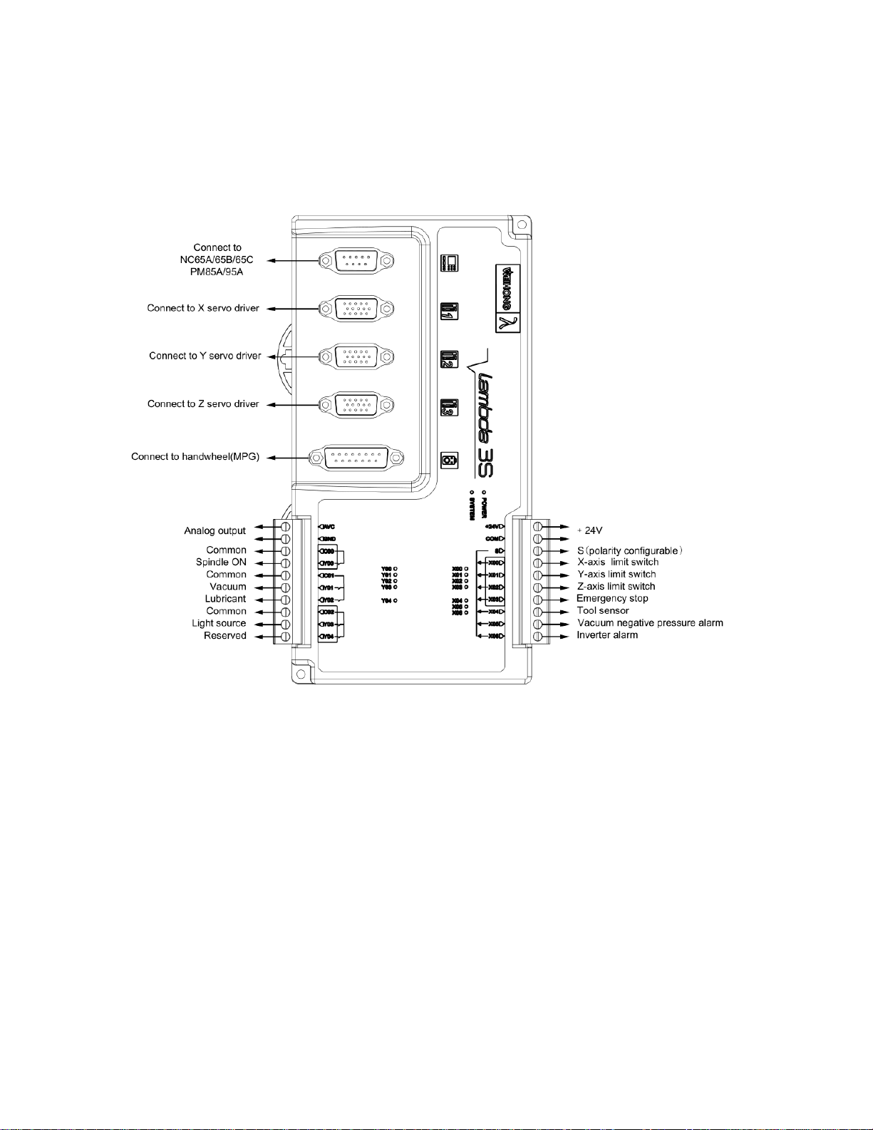
NcStudio V10 CCD System uses Lambda 3S controller.
See figure below for wiring and IO ports of Lambda 3S:
Page 6

Table below describes details of 7 input and 5 output ports.
PIN
Address
Description
X00
00100
Negative limit in X-axis, also used as origin switch
X01
00101
Negative limit in Y-axis, also used as origin switch
X02
00102
Positive limit in Z-axis, also used as origin switch
X03
00103
Emergency stop
X04
00104
Tool sensor signal
X05
00105
Vacuum pressure alarm signal
X06
00106
Spindle alarm
Y00
10016
Spindle ON
Y01
10017
Vacuum pump
Y02
10018
Lube
Y03
10019
Light source
Y04
10020
Reserved for customization
WEIHONG ELECTRONIC TECHNOLOGY CO., LTD.
- 3 -
• X__ represents input ports
• Y__ represents output ports
Page 7
Installing the Camera
WEIHONG ELECTRONIC TECHNOLOGY CO., LTD.
- 4 -
Before using NcStudio V10 CCD System, the installation of camera is required.
Dimension of the Camera and Lens
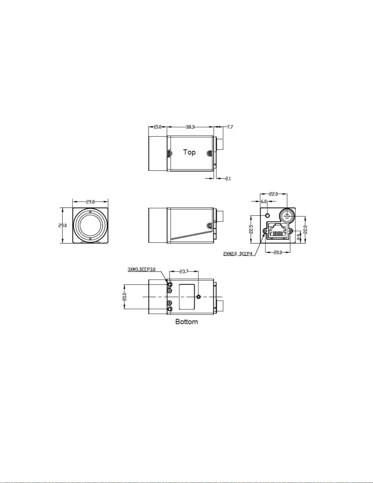
Before you install the camera, refer to dimensions of the camera and lens.
See figure below for dimension of the camera:
Page 8
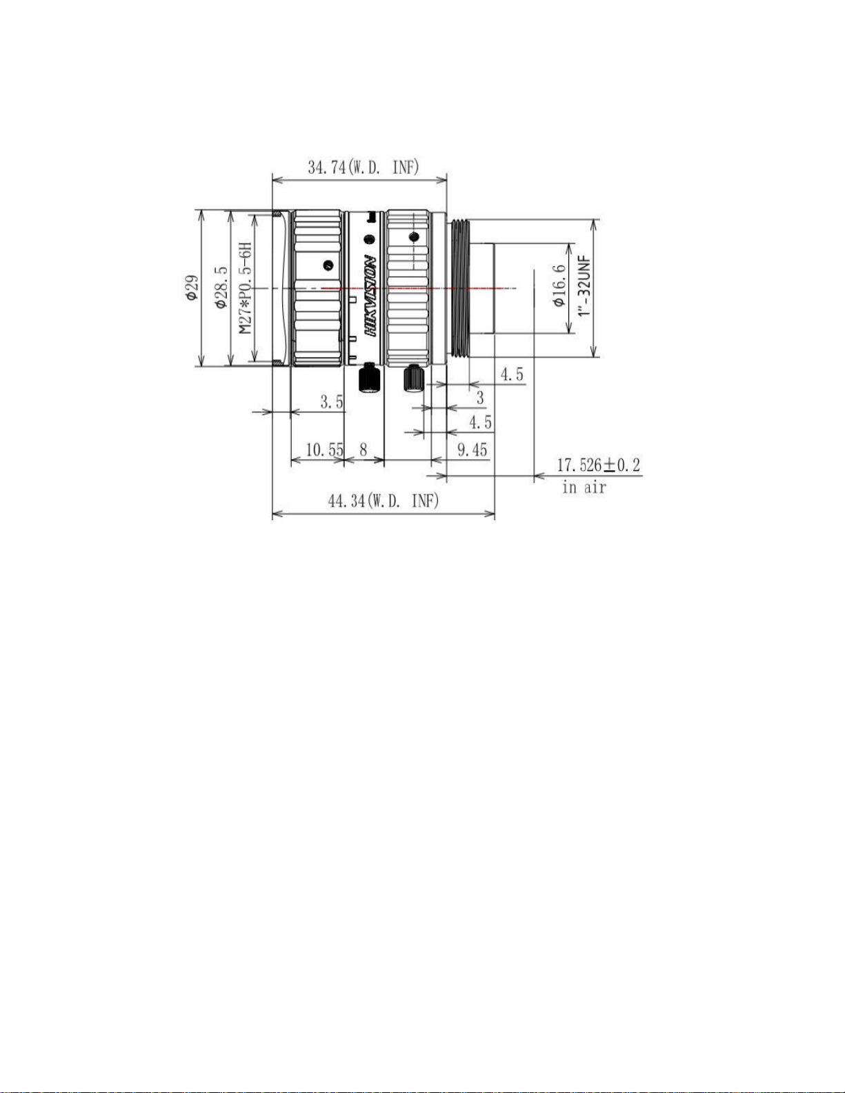
See figure below for dimension of the lens:
WEIHONG ELECTRONIC TECHNOLOGY CO., LTD.
- 5 -
To install the camera, do the following:
1. Connect the camera.
2. Install software of the camera.
Page 9
Connecting the Camera
WEIHONG ELECTRONIC TECHNOLOGY CO., LTD.
- 6 -
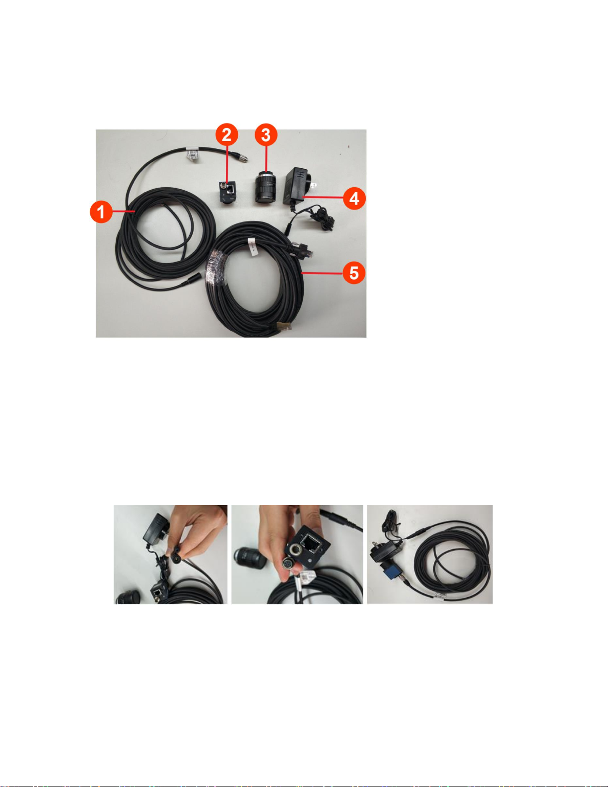
Before connecting the camera, prepare the following products:
1. Power extension cord
2. Industrial camera
3. Industrial lens
4. DC stabilized power adapter 12V
5. Industrial gigabit cable
Attention: Please ensure your computer supports gigabit network.
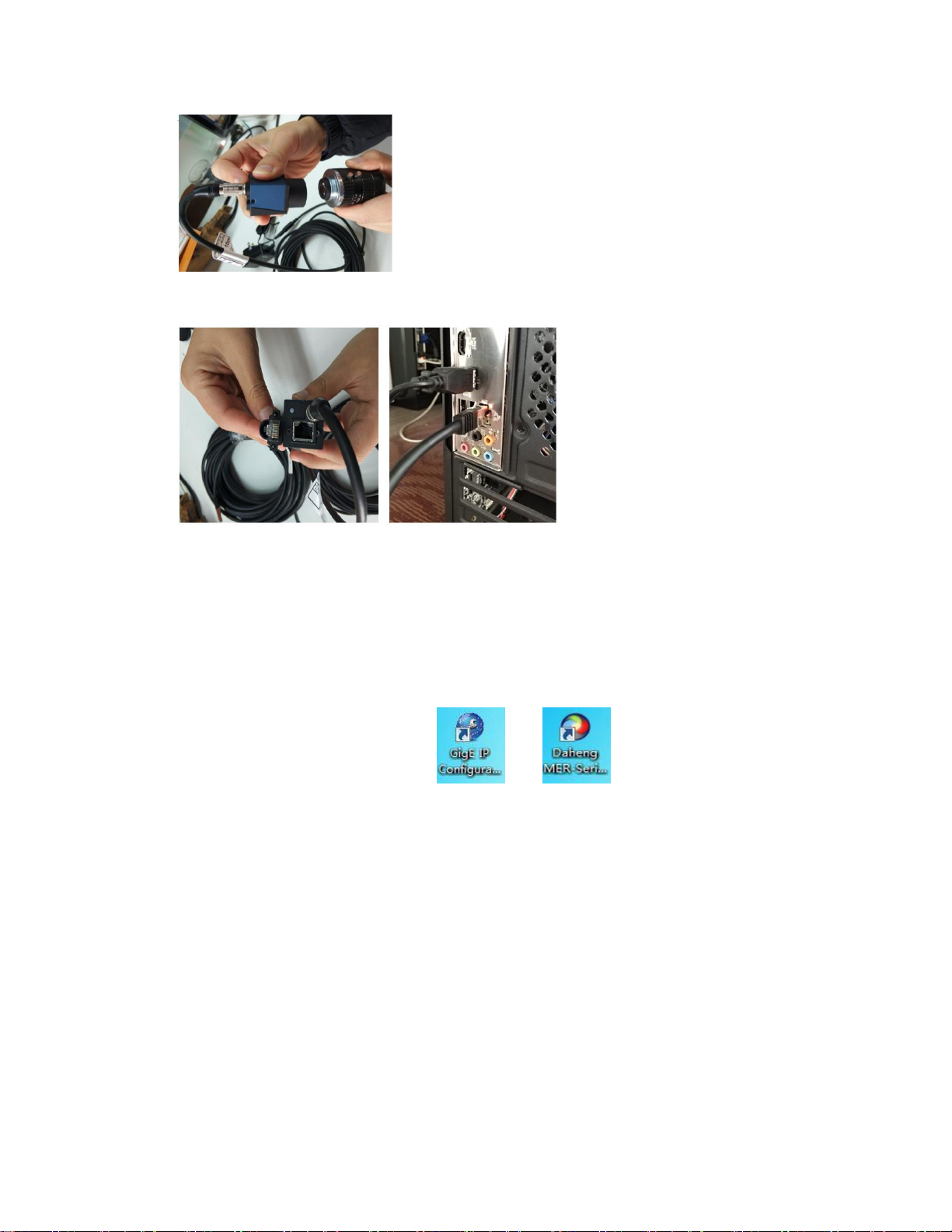
To connect the camera, do the following:
1. Connect the camera to power extension cord:
2. Remove protective cover of camera and industrial lens.
3. Connect the industrial lens to the camera:
Page 10
WEIHONG ELECTRONIC TECHNOLOGY CO., LTD.
- 7 -
4. Connect industrial gigabit cable to the camera and the computer:
Installing Software of the Camera
To install software of camera, do the following:
1. Unzip the file DAHENG_MER_Series_Win_en.rar to a local directory.
2. Double click MER_Setup_cn.exe to initiate the installation procedure.
3. Follow the setup wizard to install the camera driver until end.
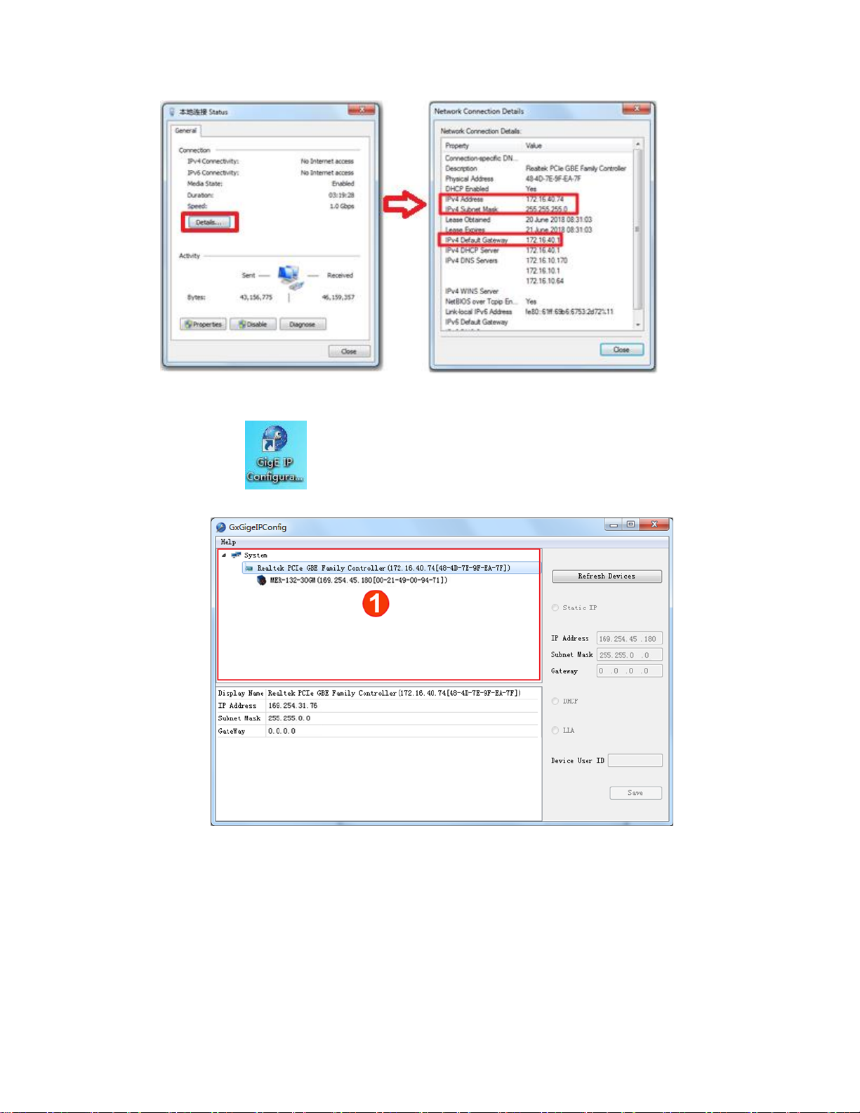
After the installation, two icons ( and ) appear on the desktop.
4. Open Control Panel → Network and Internet → Network and Sharing
Center → Local Connection → Details on your computer to check IP address,
subnet mask and gateway of your computer:
Page 11
WEIHONG ELECTRONIC TECHNOLOGY CO., LTD.
- 8 -
5. To configure static IP for the camera, do the following:
1. Click . The dialog box GxGigeIPConfig pops up.
2. Click Refresh Devices to refresh the camera list in area ①.
3. Select the camera in the camera list.
4. Check Static IP and modify the IP address of the camera to the IP
address which is on the same subnet with your computer.
Attention: The IP address of the camera and your computer
must be on the same subnet and cannot conflict with IP
addresses of other terminals. Otherwise, communication
exception occurs.
Page 12
5. Click Save to save the modification.
WEIHONG ELECTRONIC TECHNOLOGY CO., LTD.
- 9 -
Although the system can obtain IP address automatically, it is
unstable. It is suggested to manually configure static IP address.
The software is installed successfully. And the system automatically starts the
camera driver.
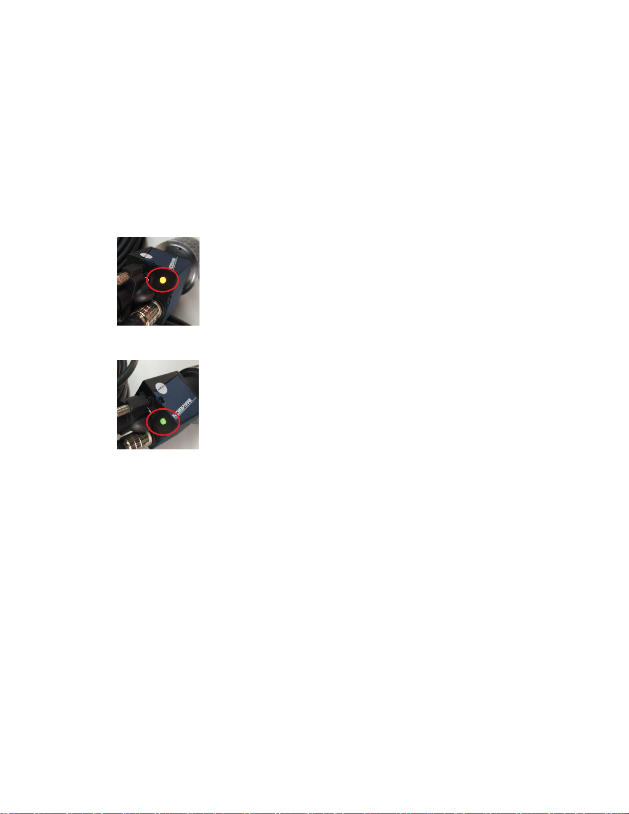
After installing the software, check the status of the camera’s indicator lamp:
• No light on: no power supply.
• Orange-red light on: power is on.
• Green light on: communication succeeds.
Page 13

CCD Commissioning
WEIHONG ELECTRONIC TECHNOLOGY CO., LTD.
- 10 -
To make CCD ready for machining, you need to adjust the camera and do some
commissioning.
Follow steps below to do the commissioning.
1. Power up and start the NC system.
2. Turn the system to Homing mode, and return all machine axes to the machine
origin.
3. Turn the system to Manual mode, Click Vision → CCD → Parameters →
Manufacturer Param → Measure to switch to Measure interface.
4. Use the function Pick Current to decide the working plane.
It is recommended to leave distance between the camera bottom to the
workpiece surface 125mm.
See Setting CCD Working Plane for details.
5. Adjust the camera, including the focal length, aperture, etc. to ensure the
camera can get a clear sight.
6. Measure the magnification of the camera.
7. Move to the shooting position.
8. Camera shoots and gets marking points.
Setting CCD Related Parameters
To make CCD ready for machining, you need firstly set related parameters, including
parameters of different access.
Prerequisite
All machine axes have returned to the machine origin.
Steps
To set CCD related parameters:
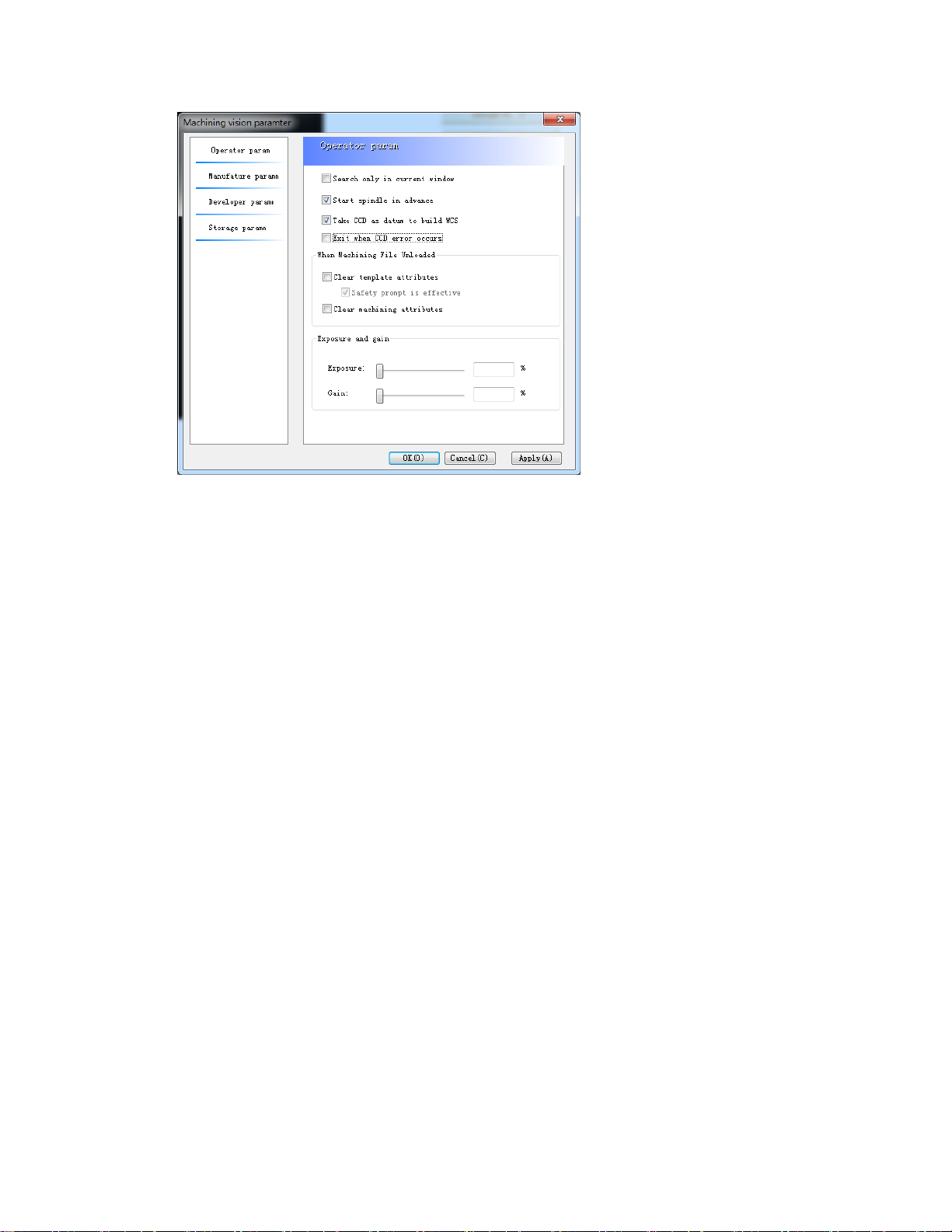
1. Click Vision → CCD → Parameters. It opens dialog box titled "Machine Vision
Parameter".
Page 14
WEIHONG ELECTRONIC TECHNOLOGY CO., LTD.
- 11 -
2. Click Operator (default)on the left side, and set parameters of operator’s
access on the right.
Following are parameters of operator’s access.
Search only in current window
If the box is checked, search only in CCD window for templates during automatic
machining in Shoot-Cut mode. Otherwise, search the whole camera sight for
templates.
Start spindle in advance
If the box is checked, start the spindle in advance once Start button is clicked.
Take CCD as datum to build WCS
If the box is checked, take CCD center as the origin to build workpiece coordinate
system; otherwise, take the spindle center as the origin to build workpiece
coordinate.
Exit when CCD error occurs
If the box is checked, the system will exit machining if there is recognition failure,
otherwise, the system will skip the path if there is recognition failure.
Clear template attributes
If the box is checked, templates and parameters of the program file will be removed
when the file is removed from the system; otherwise, templates and parameters of
the program file remained.
Page 15
Clear machining attributes
WEIHONG ELECTRONIC TECHNOLOGY CO., LTD.
- 12 -
If the box is checked, parameter settings of the program file will be removed when
the file is removed from the system; otherwise, parameters of the program file
remain.
Exposure
Drag the slide to adjust the exposure of the camera. See Exposure for its definition.
Gain
Drag the slide to adjust the gain of the camera. See Gain for its definition.
It is not recommended to set a high value.
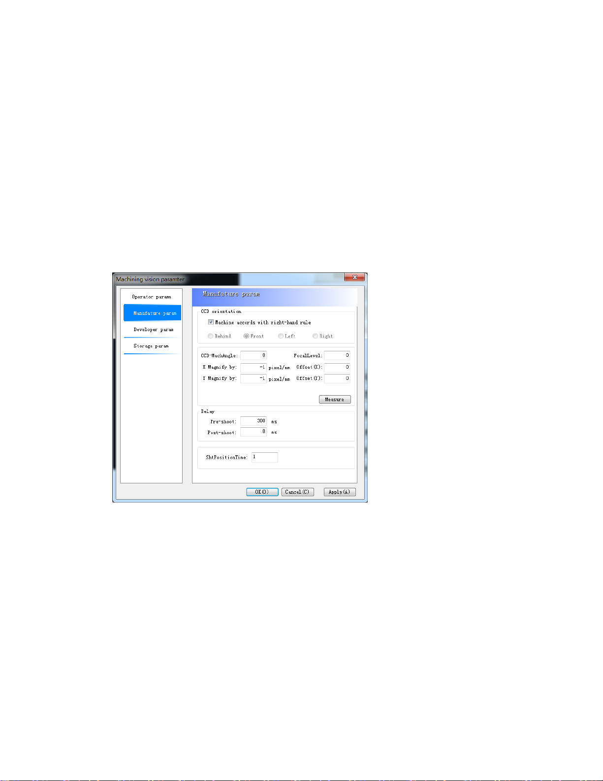
3. Click Manufacturer on the left side, and set parameters of manufacturer’s
access on the right.
CCD orientation
Sets the camera position relative to the spindle.
Only Front is supported at present. If you find the camera positions is wrong,
discharge the camera and adjust the position.
CCD-Machine angle
It sets the angle between camera and the spindle. The angle comes from the
misalignment of camera and the machine.
Magnification factors
It includes magnification factors in X-axis and Y-axis.
CCD offset
It sets distances between the camera and the spindle in X-axis and Y-axis.
Page 16
Focal Level
WEIHONG ELECTRONIC TECHNOLOGY CO., LTD.
- 13 -
It sets the height in Z-axis when the camera takes clear photos.
Pre-shoot delay
It sets the delay time to stabilize the camera before taking a photo.
Post-shoot delay
It sets the delay time after the camera takes a photo.
Shoot times
It sets how many times the camera takes photos at a shooting position.
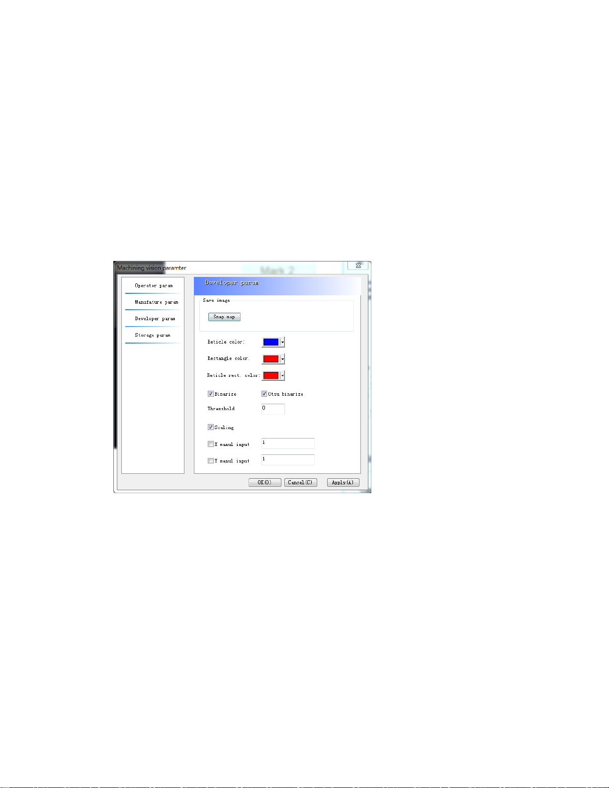
4. Click Developer on the left side, and set parameters of developer’s access on
the right.
• Click Snap image button to take photos at current position.
• It is recommended to check the box Scaling for Three-point shooting.
Setting CCD Working Plane
CCD working plane refers to the XY plane at focal height. To set the working plane is
to set the focal height in Z-axis.
Prerequisite
Well adjust focal length and aperture of the camera lens. See camera lens for details.
Steps
1. Turn the system to Manual mode, Click Vision → CCD → Parameters →
Manufacturer Param → Measure to switch to Measure interface.
Page 17

2. Adjust Z-axis height and fine tune the knob on the camera.
WEIHONG ELECTRONIC TECHNOLOGY CO., LTD.
- 14 -
3. When the photo in camera sight becomes enough clear, click Get Current. The
system records the current height.
It proves that when the magnification factor sets to 15X, the camera
gets the best adjusting result. In this case, working distance needs to
be within 120mm~130mm.
Once the working plane is set, it will be the height for Z-axis in the processes of
measuring magnification factor, CCD-spindle offset, picking template and shooting.
In addition, the height is independent to workpiece coordinate system.
Setting CCD Magnification Factor
Image takes pixel as unit, but machine moves in millimeter. Therefore, the
relationship between the pixel and millimeter is the magnification factor.
Characteristic point on the workpiece is used to decide the magnification factor.
Steps
To set parameter CCD Magnification Factor:
1. Turn the system to Manual mode, Click Vision → CCD → Parameters →
Manufacturer Param → Measure to switch to CCD Measure interface.
Page 18
WEIHONG ELECTRONIC TECHNOLOGY CO., LTD.
- 15 -
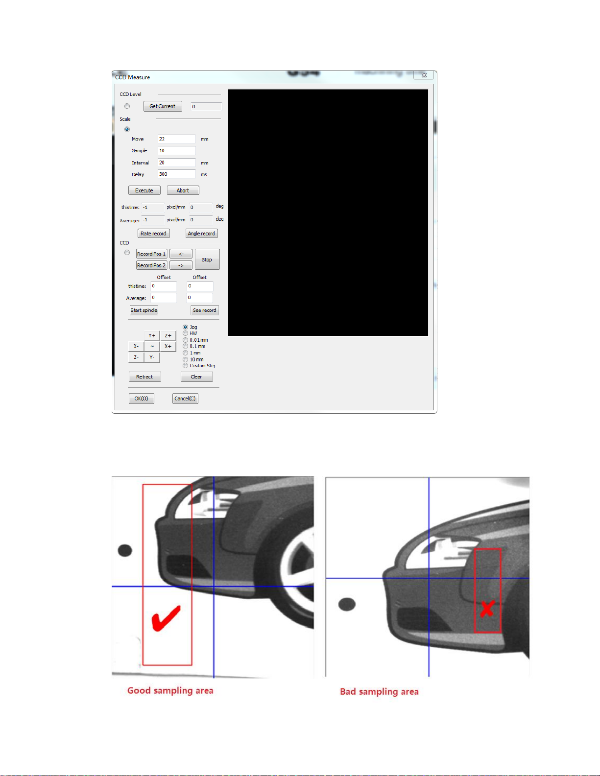
2. Adjust the machine axes to appropriate position until a clear characteristic
point appears in the right window.
Following are good and bad sampling areas.
Page 19

3. Set parameters.
WEIHONG ELECTRONIC TECHNOLOGY CO., LTD.
- 16 -
Move
It sets the moving distance of the machine.
Sample
It sets how many times that CCD shoots and acquires sample or characteristic points.
Interval
It sets the sampling interval distance.
Sampling delay
It sets the delay time before each sampling.
4. Click Execute.
The machine automatically moves and conducts measurement.
(Optional) Click Stop to suspend the sampling process.
5. Click History Record after the measurement finishes.
Magnification factor and CCD-Spindle angle of each measurement will be shown
in history records.
6. Click OK.
Average value of measuring results will be updated as camera parameter.
For repeated measurement, please clear the history record before next
measurement, to avoid possible interference.
Example
Following is parameter setting suggestion.
Moving distance: 22mm
Sampling times: 10
Sampling distance: 20mm
Sampling delay: 300
Setting CCD-spindle Offset
CCD-spindle offset refers to the distance between the camera and the spindle. It
includes X-axis offset and Y-axis offset.
Steps
1. Drill a hole on the workpiece surface.
2. Click Record Pos 1. The system records the current machine coordinates.
Page 20
3. Click left and right arrow buttons to move the camera. Stop moving the camera
WEIHONG ELECTRONIC TECHNOLOGY CO., LTD.
- 17 -
until the cross in camera center is at the hole center.
4. Click Record Pos 2. The system will automatically calculate the offsets in both
X-axis and Y-axis.
Picking Template
In shoot-cut mode, marks (also called marking point or template) are used to figure
out the tool path.
Requirements of the target marking points:
• Clear enough
• Being unique
Steps
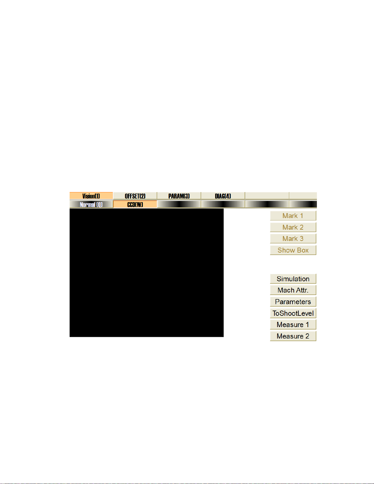
1. Turn to Manual mode, and click Vision → CCD to switch to CCD interface.
2. Click Mark 1, Mark 2 and Mark 3 in order. Three marking points will be
recorded.
Tip: For how many marking points you need to take, see Should I use
two templates or three templates?
Tip: It is recommended to take marking points at specified shooting
positions on workpiece that will be machined next.
3. Click Show Box, and select templates of different size by dragging the mouse.
Make sure characteristic of the template is obvious enough.
Page 21
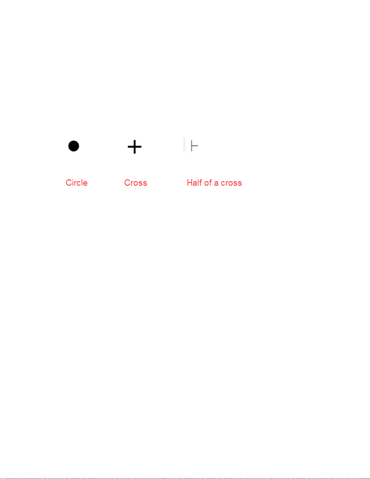
All patterns can be used as templates. For different patterns, steps to take the
WEIHONG ELECTRONIC TECHNOLOGY CO., LTD.
- 18 -
template may differ.
• If the marking point (or called shooting point) is a circle:
Move the CCD center to the circle point, and click Mark button.
• If the marking point is a cross or half of a cross:
Move the CCD center to the center point of the cross or half of a cross, and click
Mark button.
Page 22
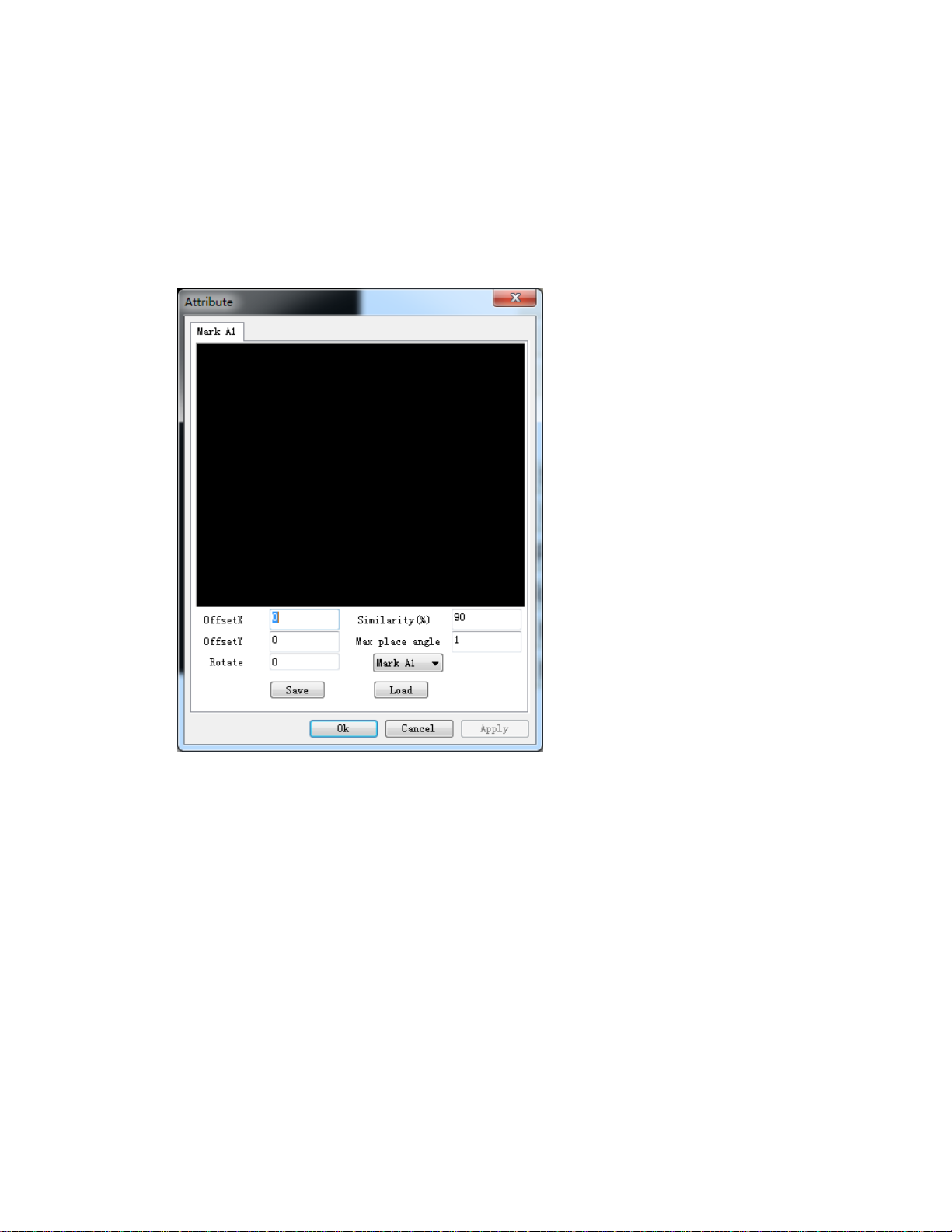
Setting Machining Attributes
WEIHONG ELECTRONIC TECHNOLOGY CO., LTD.
- 19 -
Prerequisite
You have successfully picked out marking points.
Steps
1. Click Mach Attr. to open a dialog box named “Attribute”.
2. Click Mark A1. Set parameters.
Offset X/Y
Offsets in X-axis and Y-axis, which decide the position of picking template.
Offset value can be obtained by Measure function or trial cutting.
Rotate
It refers to the plate placing angle of the position of picking template.
Similarity
Default value is 90%.
If the image is relatively clear, set the parameter to a relatively high value.
Max. place angle
Default value is 1 degree.
Page 23

It refers to the maximum angle deviation between snapping and template. If actual
WEIHONG ELECTRONIC TECHNOLOGY CO., LTD.
- 20 -
deviation exceeds this value, shooting may fail.
3. Click Apply to activate parameter settings and click OK.
Measuring Distance and Angles
Use Measure function to measure the distance or angle between two specified
points.
Steps
1. Move the machine axes to one point, and click Measure 1.
2. Move the machine axes to another point, and click Measure 2.
The system will calculate the results.
Note that the angle refers to the angle relative to the positive
direction of X-axis.
Preparing Toolpath
At present, CCD system supports two kinds of working modes:
• General engraving mode
No marking points or shooting points are needed. The system is used as a
general engraving control system.
• Machining with marking points
– Retrieving toolpath from a .jpg file
– Importing toolpath from a .dxf file
Retrieving Contour from JPG File
By setting related parameters, the control system can automatically retrieve contour
from a JPG file.
Do the following to retrieve contour from a JPG file.
Steps
1. Launch NcStudio, and switch to NcEditor interface.
2. Click File → Import JPG file…. A dialog box named Open opens.
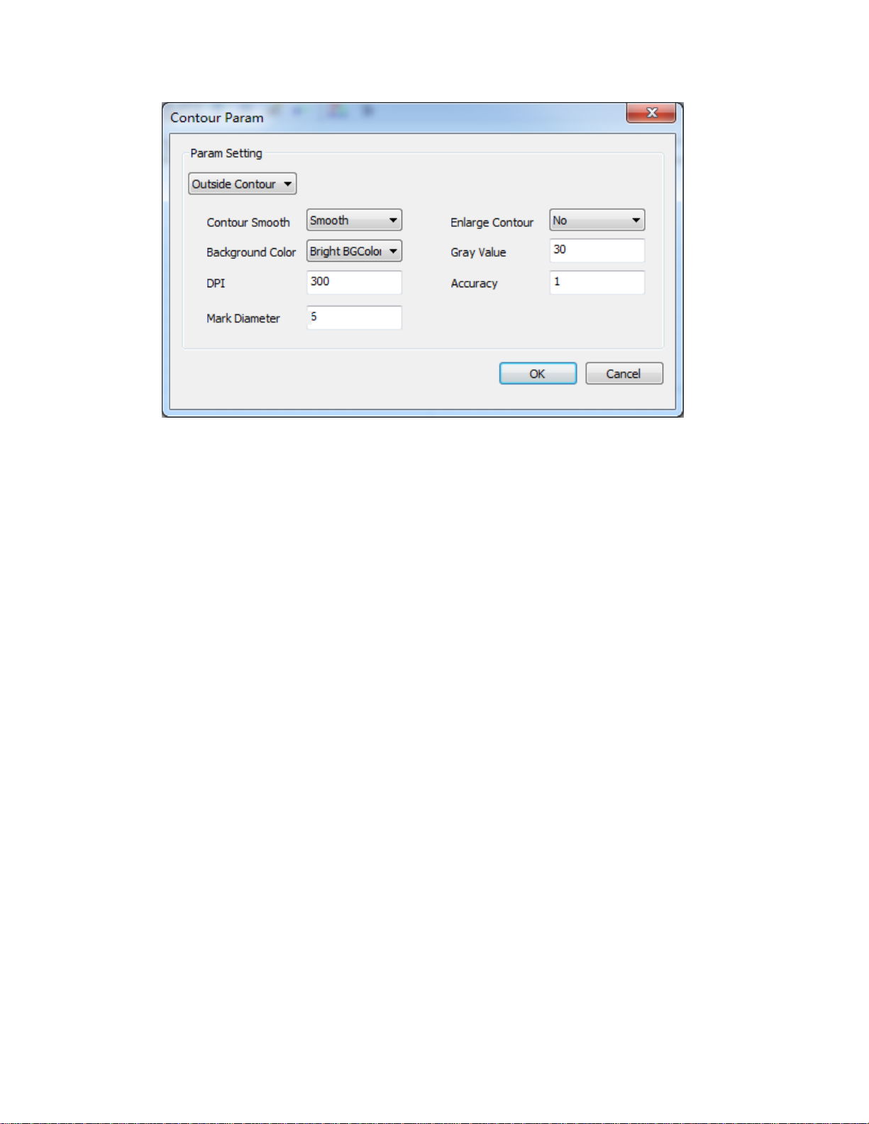
3. Select the target .jpg file. A dialog box named Contour Param opens.
Page 24
WEIHONG ELECTRONIC TECHNOLOGY CO., LTD.
- 21 -
4. Set related parameters. See Related Parameters for details.
5. Click OK.
By default, the system will automatically do followings to deal with the
imported .jpg file and retrieve the contour.
1. Converting color to grayscale according to setting value of Grayscale
parameter.
2. Pixel scaling.
3. Adjusting distance between marking points.
4. Automatically recognize marking points.
5. Finishing contour retrieving.
Related Parameters
Followings are related parameters that influence the contour retrieved from JPG
image. You can get how each parameter works through comparison and make your
own decision.
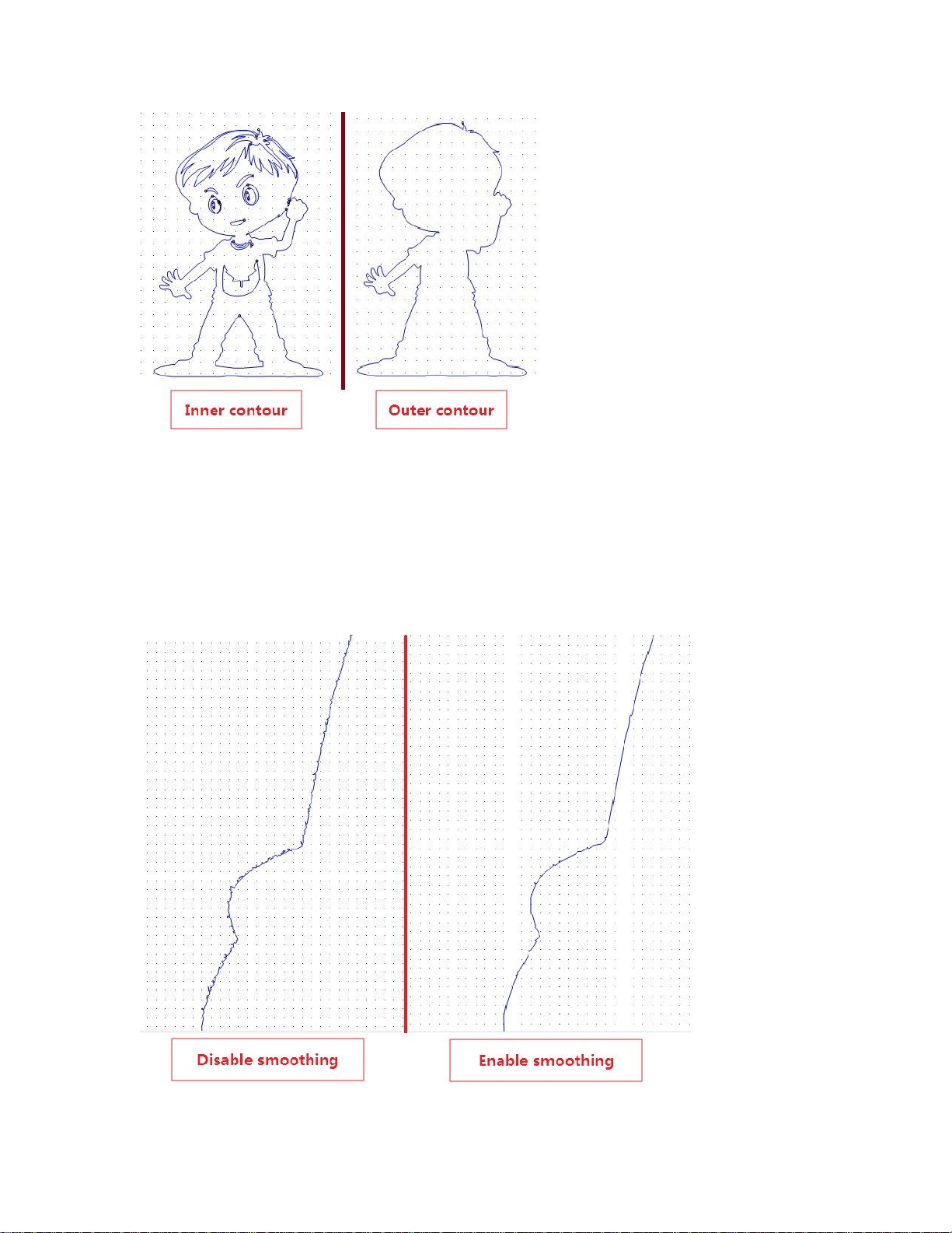
Inner or Outer Contour
Inner contour means to retrieve the inside part of the imported .jpg file. Outer
contour means to retrieve the outside part of the imported .jpg file.
See figure below for comparison.
Page 25
WEIHONG ELECTRONIC TECHNOLOGY CO., LTD.
- 22 -
Smoothing Contour
To smooth or not smooth the contour.
If the imported image file has relatively low resolution or the edges of the contour
are vague, use the Smoothing contour function to remove bad points and smooth
the path.
See figure below for comparison.
Page 26
Enlarge Contour Line
WEIHONG ELECTRONIC TECHNOLOGY CO., LTD.
- 23 -
To retrieve relatively thin lines, use Enlarge contour line function to magnify the
contour.
It does not affect the actual machining size.
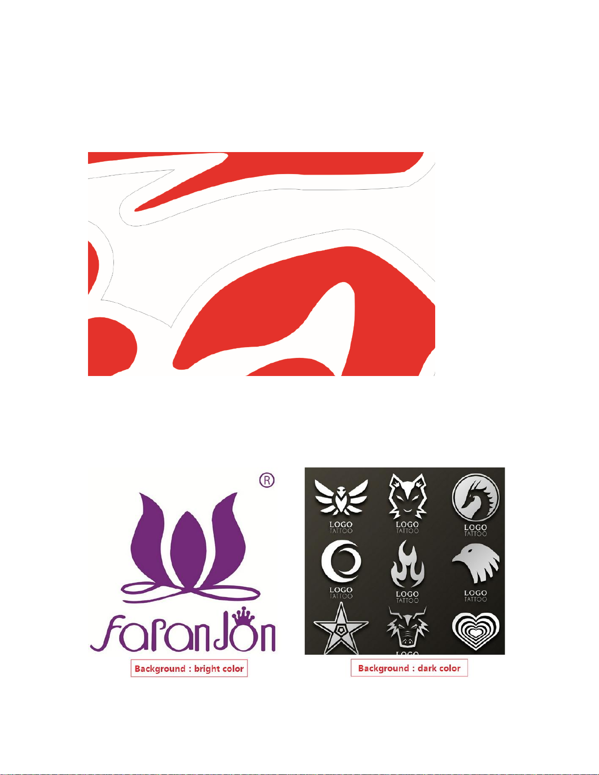
Background Color
Choose the background color according to the imported image.
See figure below for images with bright color background and dark color
background.
Page 27
DPI
WEIHONG ELECTRONIC TECHNOLOGY CO., LTD.
- 24 -
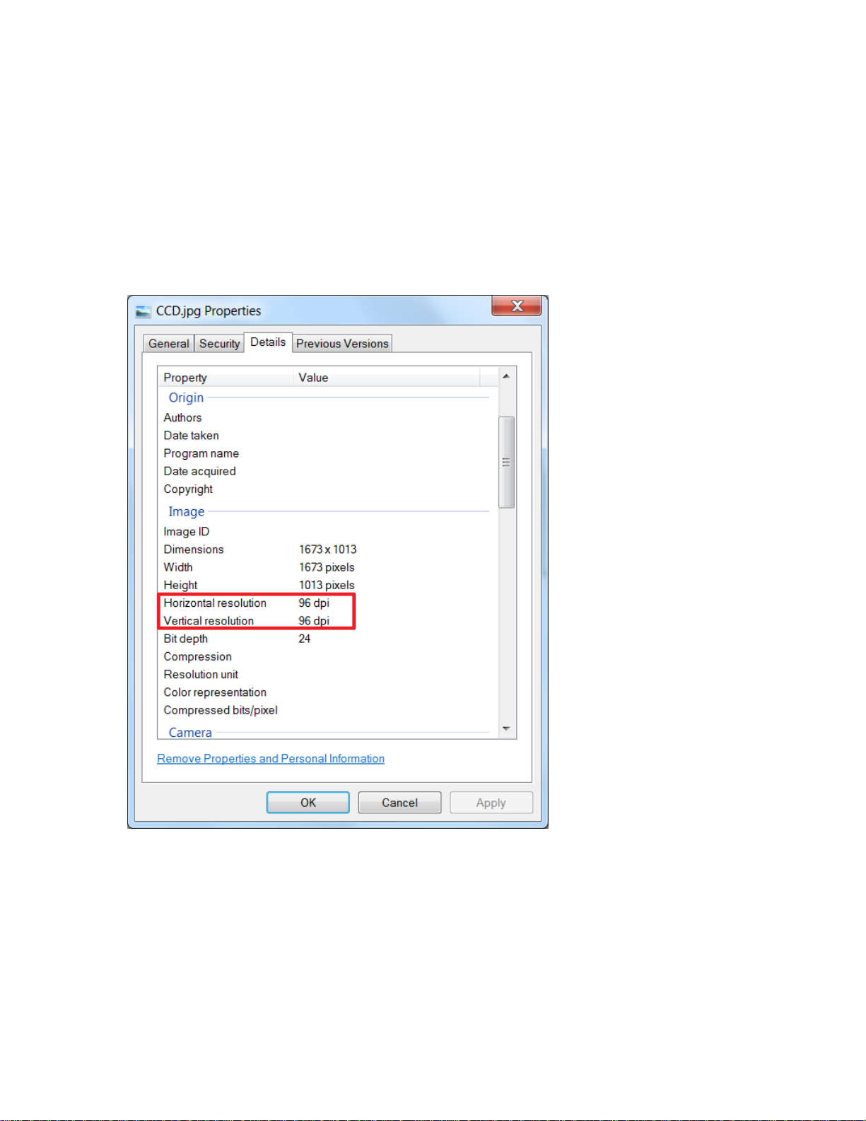
Dots Per Inch, is a measure of spatial printing or video or image scanner dot density,
in particular the number of individual dots that can be placed in a line within the
span of 1 inch (2.54cm).
How to check DPI of an image:
1. Right-click on the image file, and select Property.
2. Switch to tab Details. You can get detailed information about the image.
Greyscale
In photograph, computing, and colorimetry, a greyscale or greyscale image is one in
which the value of each pixel is a single sample representing only an amount of light,
that is, it carries only intensity information. Images of this sort, also known as blackand-white or monochrome, are composed exclusively of shades of gray, varying
from black at the weakest intensity (0) to white at the strongest (255).
Best practices for setting greyscale:
Page 28
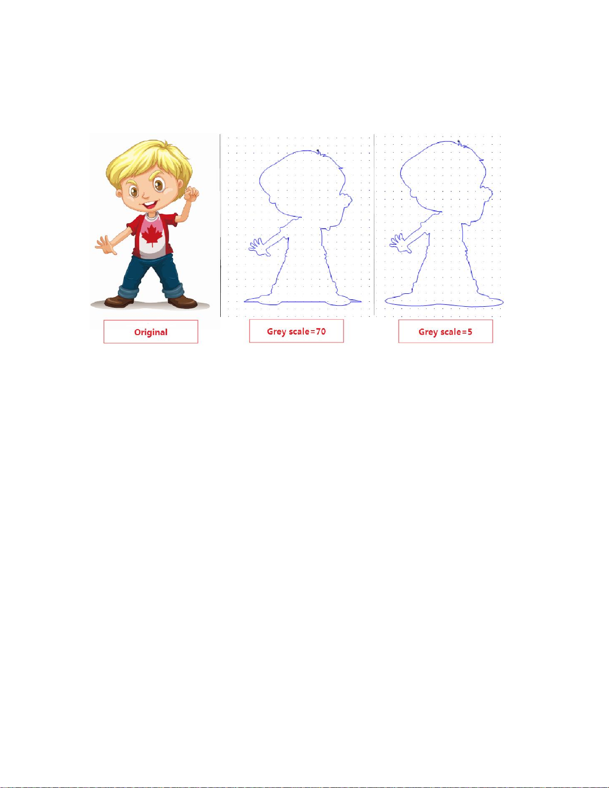
• For images with light color background, set low greyscale.
WEIHONG ELECTRONIC TECHNOLOGY CO., LTD.
- 25 -
• For images with dark color background set high greyscale.
See figure below for comparison.
Precision
Default value is 1.
Precision will affect the distance between two marking points and how many
marking points can be retrieved.
Relationship among precision, distance between marking points and number of
marking points are:
• Higher precision, larger marking points distance, less marking points.
• Lower precision, smaller marking points distance, more marking points.
Page 29
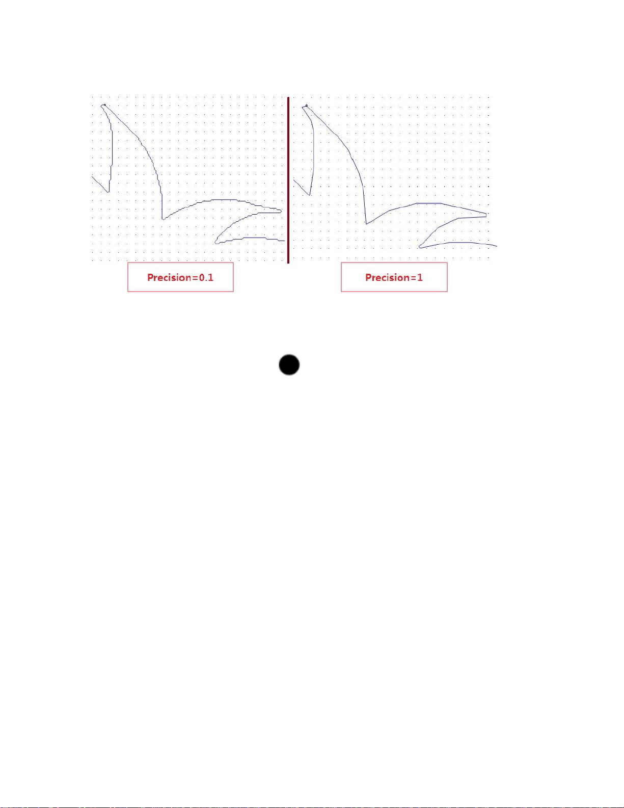
See figure below for comparison.
WEIHONG ELECTRONIC TECHNOLOGY CO., LTD.
- 26 -
Marking Point Diameter
At present, the system can automatically recognize marking points of circular type.
For marking points of circular type , the system will do the following:
1. Calculate the contour area of the circle.
Area = πr² //r represents circle diameter, namely, setting value of
Mark point diameter parameter
2. Make a threshold according to the result of circle area.
Threshold: [-(20%*Area), +(20%*Area)]
3. According to the threshold, pick out all circles whose diameters are within the
range and make them marking points.
For circles whose diameters are smaller than the minimum value of the
threshold, they will be recognized as useless points and be ignored in retrieving
process.
Editing Toolpath
After retrieving contour from a JPG file, users can edit the contour and convert it to
toolpath that is ready for machining.
Users need to do followings when editing toolpath:
1. Setting workpiece origin.
2. Setting machining direction.
3. Setting tool compensation.
Page 30
4. Setting lead lines.
WEIHONG ELECTRONIC TECHNOLOGY CO., LTD.
- 27 -
5. Deciding active objects.
6. Setting in-process parameters.
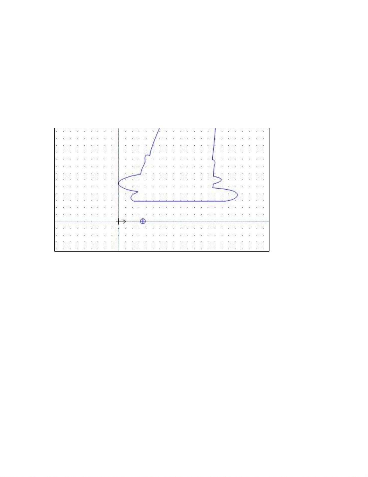
Setting Workpiece Origin
After contour is retrieved and has been imported it into the system, a default
workpiece origin will be defined at the lower-left of the contour.
See figure below for default workpiece origin.
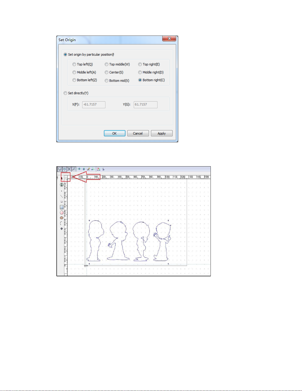
Do one of the followings to modify the workpiece origin.
• Click Draw → Set Origin and set the workpiece origin in the pop-up dialog box.
– (Recommended) Select the position of the marking point that will be
used as the workpiece origin.
– Directly enter X, Y coordinates of the workpiece origin.
Page 31
WEIHONG ELECTRONIC TECHNOLOGY CO., LTD.
- 28 -
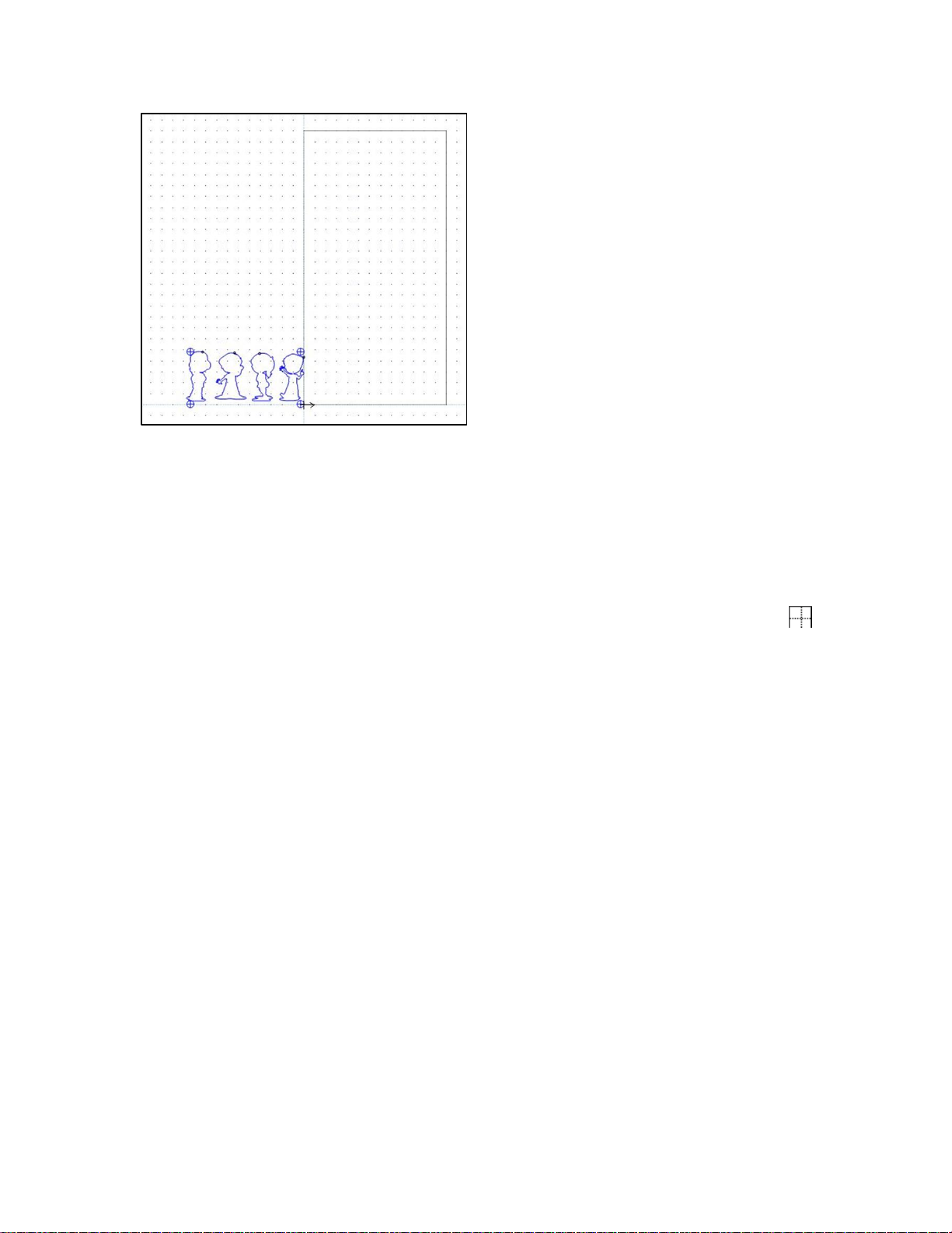
• Turn to NcEditor interface and drag icon with left mouse to target workpiece
origin position.
See figure below for the toolpath that has defined the workpiece origin.
Page 32
WEIHONG ELECTRONIC TECHNOLOGY CO., LTD.
- 29 -
After the workpiece origin is defined, the system can know workpiece coordinates
of each marking point.
Setting Machining Direction
Before you begin, import the contour that has been retrieved into the system.
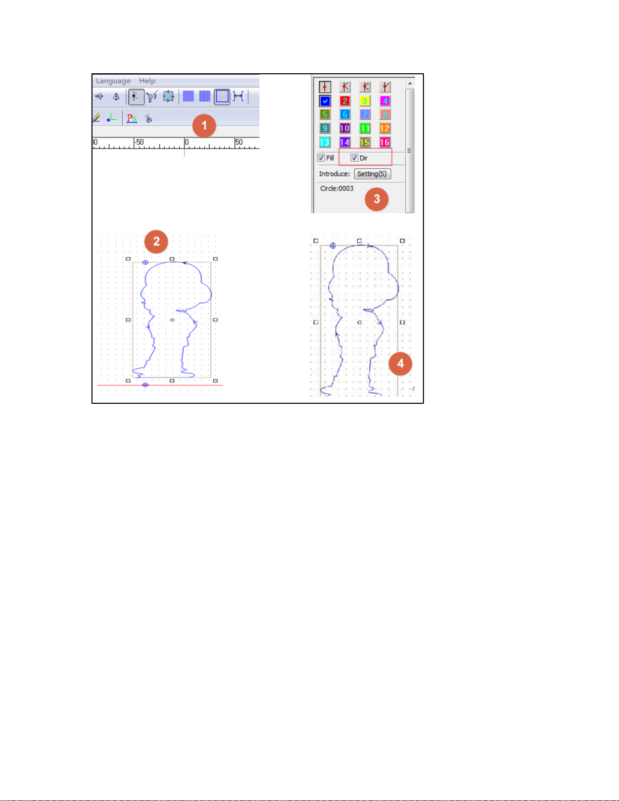
Do the following to set machining direction.
1. Turn to NcEditor interface, and click show/hide machining direction icon
on the tool bar.
2. Select the contour whose machining direction needs to be set in the drawing
area.
3. On the Property pane, check the setting of Direction parameter.
– If Direction parameter has been checked already, uncheck it.
– If Direction parameter has not been checked, check it.
4. Check the machining direction in the drawing area.
Example:
See figure below for how to set machining direction.
Page 33
WEIHONG ELECTRONIC TECHNOLOGY CO., LTD.
- 30 -
Setting Tool Compensation
In real machining scenario, users need to make tool compensation to improve
engraving precision.
Steps
Do as following to set tool compensation.
1. Turn to NcEditor interface, and select the contour that is ready for machining.
2. Click Object → Toolpath. It opens a dialog box named Toolpath.
3. Set parameters as demand.
Following are related parameters.
Compensation type
It decides what the actual toolpath look like compared with original contour. It
includes two types: shrink and extend.
Shrink: The actual toolpath deviates inward by distance that is decided by setting
value of Shrink parameter, compared with the original contour.
Extend: The actual toolpath deviates outward by distance that is decided by setting
value of Extend parameter, compared with the original contour.
Page 34
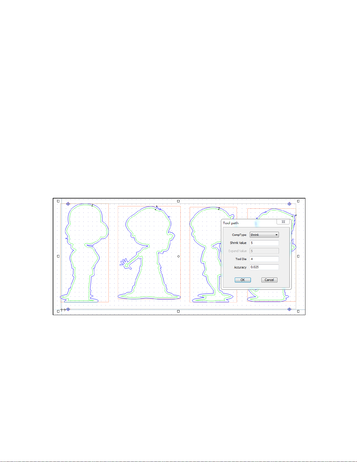
Shrink
WEIHONG ELECTRONIC TECHNOLOGY CO., LTD.
- 31 -
The distance between the shrinked toolpath and original contour. Default unit: mm.
Extend
The distance between the extended toolpath and original contour. Default unit: mm.
Tool diameter
Diameter of the tool. Default unit: mm.
Examples
Following are examples of how to set the tool compensation.
Blue color represents the original contour; and green color represents the actual
toolpath with tool compensation.
Shrink
See figure below for the preview.
Page 35
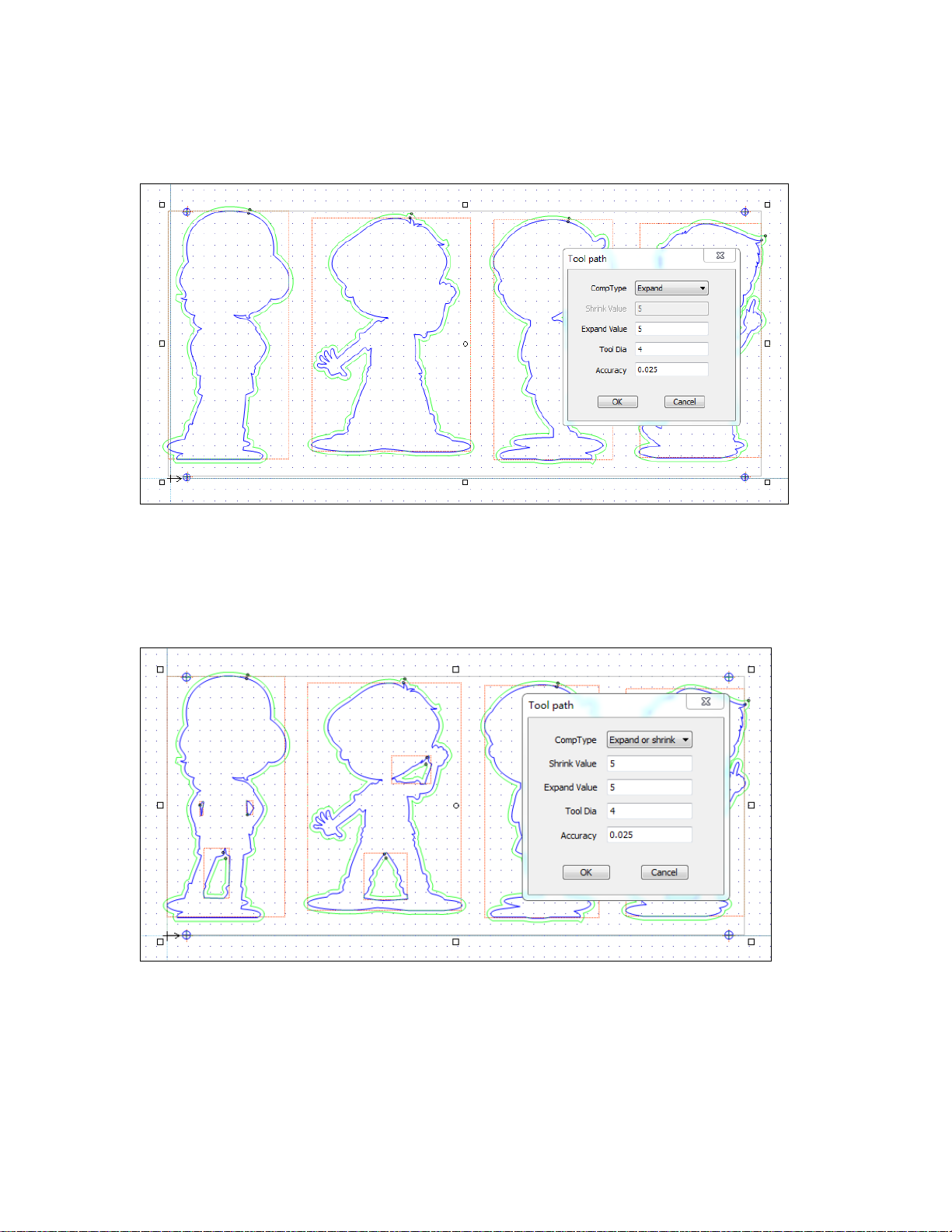
Extend
WEIHONG ELECTRONIC TECHNOLOGY CO., LTD.
- 32 -
See figure below for the preview.
Shrink the internal contour and extend the external contour
If the original contour includes nested objects, it is recommended to shrink the
internal contour and extend the external contour.
See figure below for the preview.
Page 36
Adding Lead Lines
WEIHONG ELECTRONIC TECHNOLOGY CO., LTD.
- 33 -
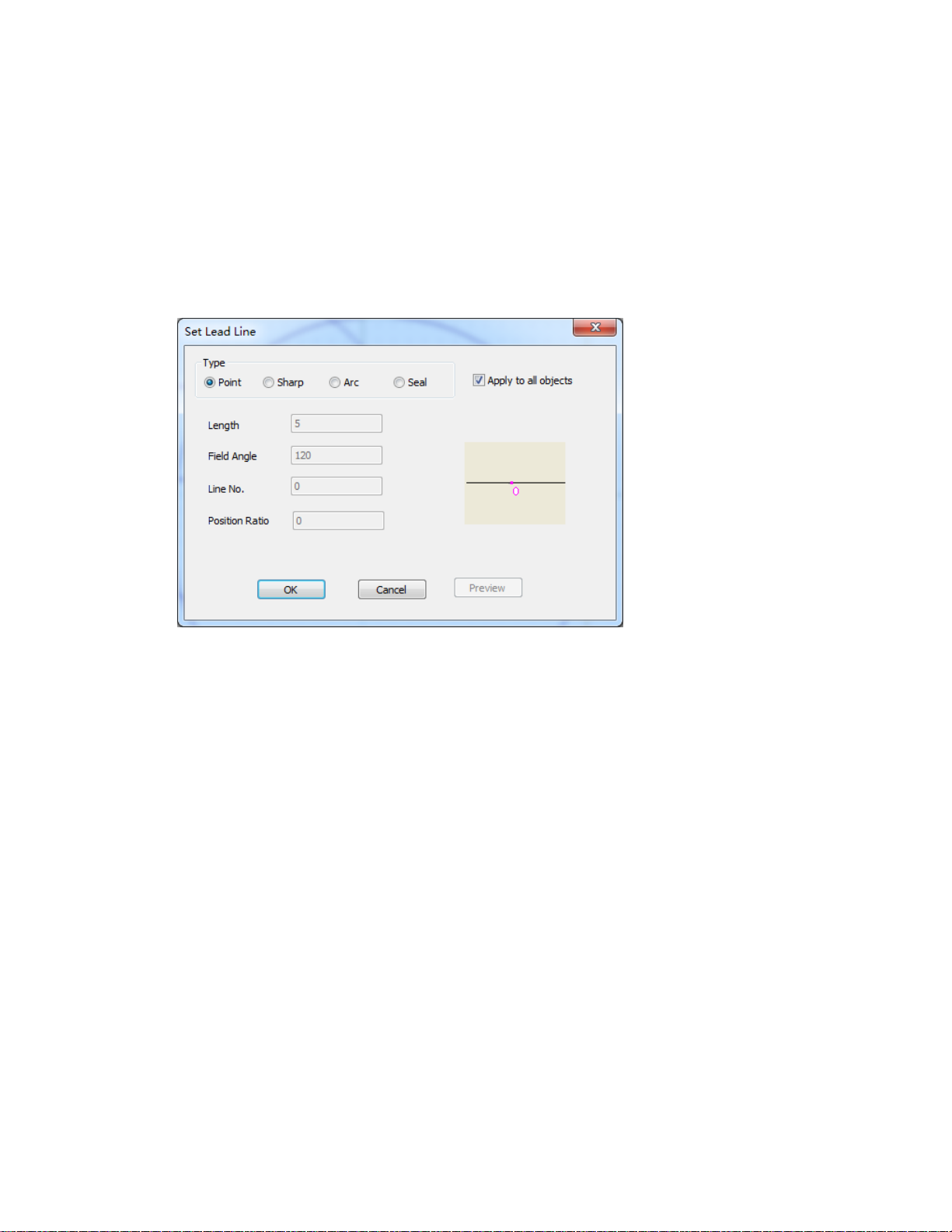
Setting lead lines decide where and how to start the cutting.
Steps
Do the following to add lead lines for machining.
1. Turn to NcEditor interface.
2. Click Object → Set lead line. It opens the Set lead line dialog box.
3. Select the lead line type, and set parameters.
4. (Optional) Check the box Apply to all objects if you want to add the lead line to
all contours.
5. Click OK
Types of Lead Lines
According to the shape, lead lines include four types:
• Dot
• Acute angle
• Arc
• Seal
Except for dot, the other three lead lines are only effective for closed graphic.
According to the position, lead lines include two types:
• Internal lead line
• External lead line
Page 37

Deciding Active Objects
WEIHONG ELECTRONIC TECHNOLOGY CO., LTD.
- 34 -
To decide the contour will be machined or not this time.
Steps
Do the following to decide the contour or object to be machined or not.
1. Turn to NcEditor interface and select the contour.
2. Right click on the contour, and select Not to machine menu on the pop-up list.
When machining starts, this contour will be skipped.
3. (Optional) Right click on the selected contour, and select Machine menu on the
pop-up list. When machining starts, this contour will be machined as required.
Setting Layer and Parameters
NcEditor takes objects that have the same parameter settings as a layer by default.
Each layer is represented in a color. That is, if you modify a parameter of one layer
in one color, the parameter setting of all objects in this layer will be updated.
Convert DXF File to Toolpath
A DXF file can be directly imported to the system and converted to toolpath.
Steps
1. Prepare DXF file.
1. Draw in AutoCAD or other drawing software.
2. Add marks to the objects.
3. Save the drawing as .dxf file format.
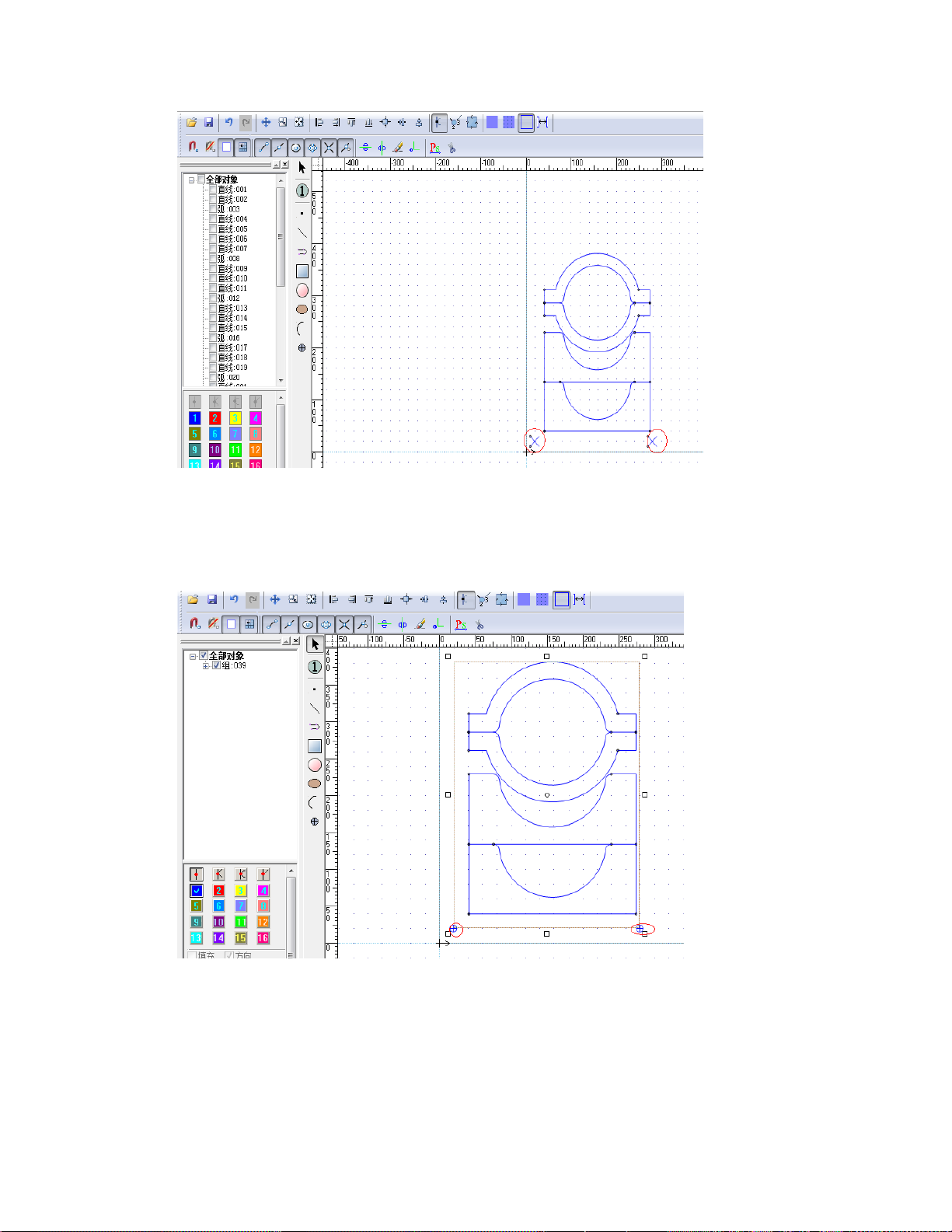
2. Launch NcStudio, and switch to NcEditor interface. Click File → Import DXF
file to import the prepared .dxf file into NcEditor.
Page 38
WEIHONG ELECTRONIC TECHNOLOGY CO., LTD.
- 35 -
3. (Optional) According to the desired cutting quantity and position, set arraying
related parameters.
4. Adding marking points. Click the cross icon on the tool bar, and replace the
marks with cross icon to add marking points.
Shooting points must be nearby the characteristic points or the marks.
5. Click Object → Toolpath to set tool compensation.
6. Frame check all contour and marking points, and right click the mouse, select
Group.
Page 39

All toolpaths or objects that have used marking points must be
WEIHONG ELECTRONIC TECHNOLOGY CO., LTD.
- 36 -
grouped before being saved as program file.
7. Save the file as .nce program file.
Page 40

Running the Toolpath
WEIHONG ELECTRONIC TECHNOLOGY CO., LTD.
- 37 -
Prerequisite
Before you start automatic running the program, make sure the following:
• All machine axes have returned to the machine origin.
• CCD commissioning has been done.
• Related parameters have been well set.
• Toolpath has been imported into the system.
Steps
Turn to Auto mode, and click Start.
To sum up, an overall machining process goes like:
1. Launch NcStudio system.
2. Return all machine axes to the machine origin.
Is the first-time machining for the graphic?
– Yes: turn to step 3
– No: turn to step 7
3. Turn to NcEditor interface, and import .jpg image file into NcEditor.
4. Edit the toolpath and save it as .nce program file.
5. Move to the shooting position and get marking points.
Are the marking points correct?
– Yes: turn to Manual mode, move the camera center to any shooting
center, and click Mark 1, Mark 2, Mark 3 in order.
– No: turn to Manual mode, move the camera center to the actual position
corresponding to marking point 1, and click Mark 1; move the camera
center to the actual position corresponding to marking point 2, and click
Mark 2; move the camera center to the actual position corresponding to
marking point 3, and click Mark 3.
6. Click CCD → Property, and set image similarity.
7. Move the camera center to specified workpiece origin in NcEditor and clear
coordinates to zero.
8. Turn to Auto mode, and click Start.
Page 41
FAQs
WEIHONG ELECTRONIC TECHNOLOGY CO., LTD.
- 38 -
Frequently-asked questions.
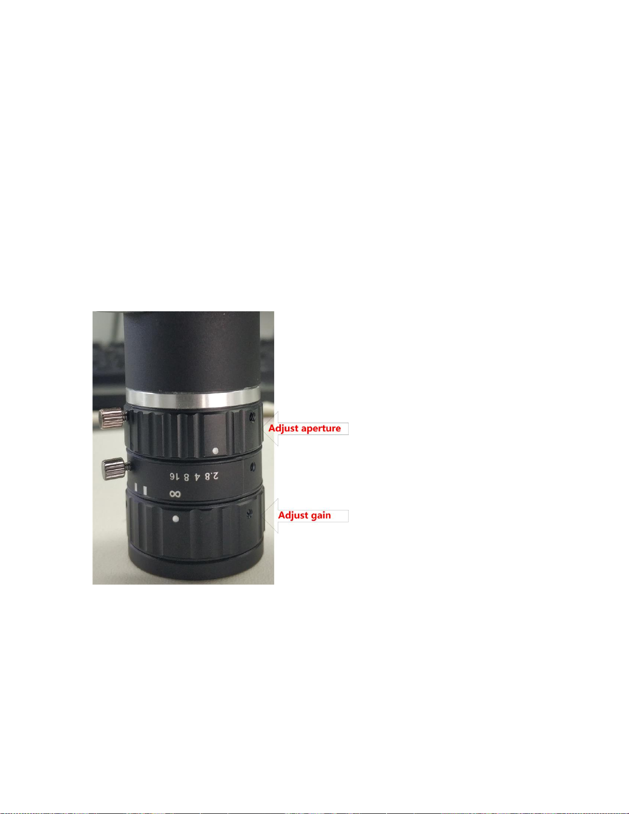
How to set aperture of the camera lens?
In NcStudio V10 CCD system, the camera lens is used, whose f-number (aperture)
ranges from F2.8 to F16.
Following are suggestions to adjust the f-number.
• If there are several light sources on the spot, it is suggested to set f-number to
F2.8, in order to ensure enough light passing through the lens.
• If there is individual light source for the camera, it is suggested to set f-number
to F4, in order to balance the depth of field and light passing through the lens.
See figure below for where to adjust aperture on the lens.
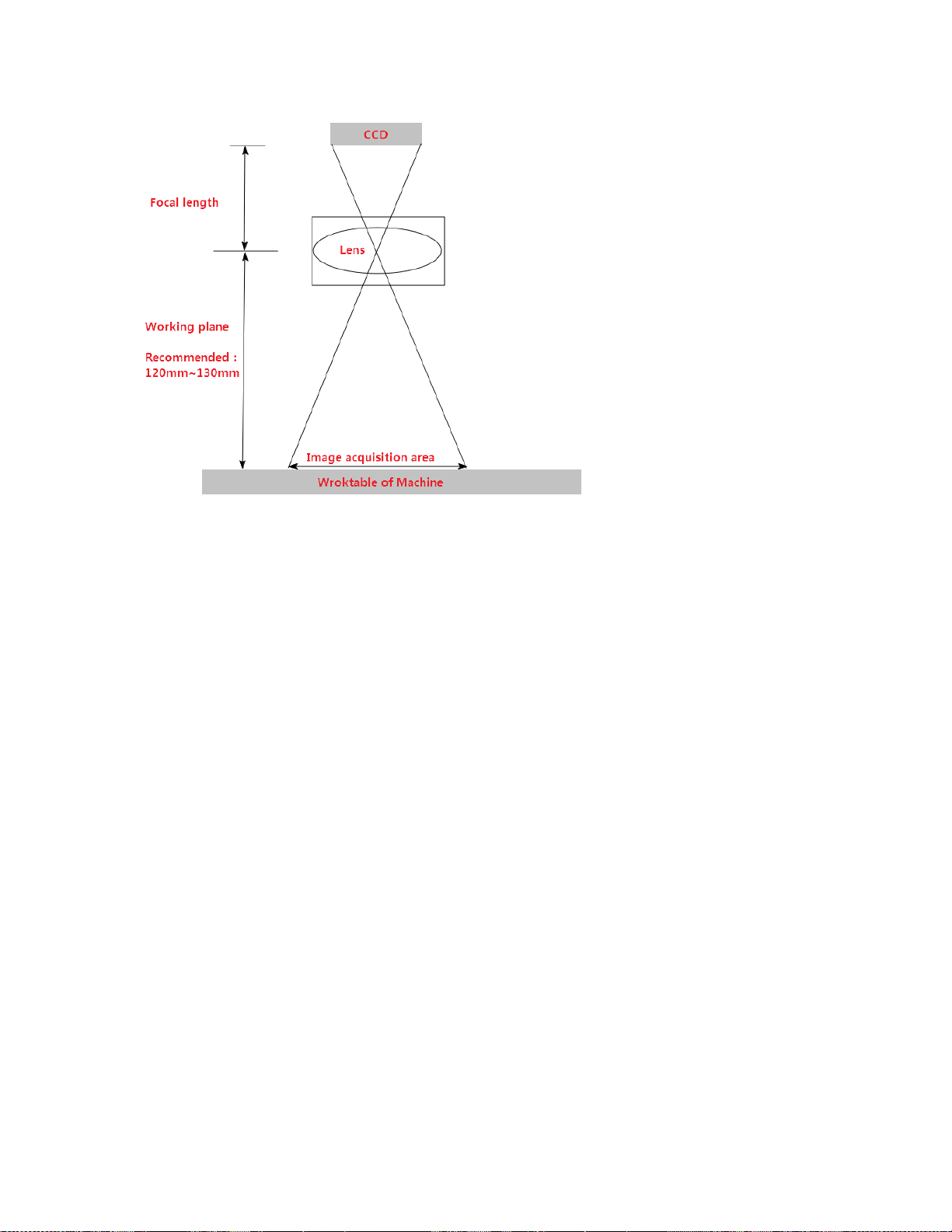
What’s the relationship among the focal length, aperture and
working distance?
CCD camera equals to a lens. See figure below for the light traveling road after going
through the lens.
Page 42
WEIHONG ELECTRONIC TECHNOLOGY CO., LTD.
- 39 -
Should I use two templates or three templates when getting
marking points?
When getting marking points, users need to decide the template number as actual
cutting demand.
• Two templates can be used to adjust plate placing angle, and meet the demand
of most cutting scenarios.
• Three templates are more precise and reliable.
Page 43

Glossary
WEIHONG ELECTRONIC TECHNOLOGY CO., LTD.
- 40 -
This part lists important concepts and terms in CCD software.
Focal length
The focal length of an optical system is a measure of how strongly the system
converges or diverges light. A system with a shorter focal length has greater optical
power than one with a long focal length.
Gain
Adjusting the gain of the camera can adjust the contrast between black color and
white color of image. It is recommended not to set a high value.
Exposure
In photography, exposure is the amount of light per unit area (the image plane
luminance times the exposure time) reaching a photographic film or electronic
image sensor, as determined by shutter speed, lens aperture and scene luminance.
Spindle-CCD offset
It specifies the distance between the centerline of the spindle and CCD.
Aperture
Adjustment of the lens opening measured as f-number, which controls the amount
of light passing through the lens. Aperture also has an effect on depth of field and
diffraction. The higher the f-number, the smaller the opening, the less light, the
greater the depth of field, and the more the diffraction blur.
Working distance
It refers to the distance between workpiece and the front-end of the camera lens
when image is within the focal length.
A shorter working distance gets smaller camera angle and higher magnification
factor. On the contrary, a longer working distance gets bigger camera angle and
lower magnification factor.
Page 44

SPECIALIZED / CONCENTRATED / FOCUSED
Shanghai Weihong Electronic Technology Co., Ltd.
Address: No. 1590, Huhang Rd., Fengxian, Shanghai, China, 201401
Hot-line: 400 882 9188
Website: www.weihong.com.cn/en
 Loading...