

Page 1
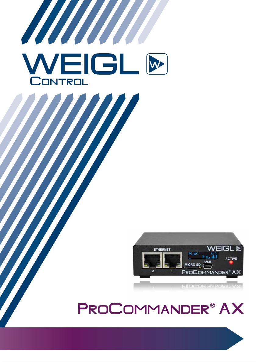
Instruction Manual
Page 2
Weigl GmbH & Co KG
+43 650 84 333 48
www.WeiglControl.com
Weigl Control (except Americas)
Weigl Works, LLC
+1 440 941 5849
www.WeiglControls.com
Weigl Control Americas
ProCommander® AX
Version 1.01
© 2018 – Weigl GmbH & Co KG
Page 3

Table Of Contents
1 Important Information and Safety Tips .5
1.1 FCC and CE Compliance .............................8
1.2 FCC Instruction to User ............................... 8
1.3 FCC DECLARATION OF CONFORMITY....10
1.4 CE DECLARATION OF CONFORMITY ...... 11
2 Warranty ...............................................13
3 ProCommander
3.1 ProCommander® AX FRONT ....................15
3.1.1 Pin assignment FRONT ....................... 15
3.2 ProCommander® AX REAR ....................... 18
3.2.1 Pin assignment REAR .......................... 18
3.3 ProCommander® AX REAR Gecko (Vendor
specific, special order) ..............................21
3.3.1 Pin assignment REAR Gecko .............. 21
3.4 ProCommander® AX Display ....................24
3.4.1 ProCommander® AX Outputs ............. 24
3.4.2 ProCommander® AX Sub-Device-ID ...25
3.4.3 ProCommander® AX Loudspeaker ..... 26
®
AX Pin Assignment ..15
4 ProCommander®AX Update .................27
4.1 ProCommander® AX Firmware Update ... 27
4.2 Wi-Fi Module Firmware Update ................ 33
5 ProCommander®AX Wi-Fi
Configuration .......................................41
5.1 Setup Wi-Fi Configuration ......................... 41
5.2 Network Configuration ..............................43
5.2.1 WLAN IP Address Configuration ........43
5.3 Tunnel Configuration .................................44
5.4 WLAN Profile Configuration ...................... 45
6 Analog MIN- and MAX-value ...............47
Page 4

7 Variable ................................................49
8 Control.ini .............................................51
8.1 Structure of the Control.ini file .................52
8.1.1 !i: Input events ..................................... 52
8.1.2 !t: Time events .................................... 52
8.1.3 !v: Variable events .............................. 53
8.2 Case studies ............................................... 56
8.2.1 Project 1 – The first show runs in a loop
and is interrupted by the second show
every 45 minutes .................................56
8.2.2 Project 2 – Three switches trigger three
shows ................................................... 57
8.2.3 Project 3 – One area has to be filled with
four different recorded voice sounds 59
8.2.4 Project 4 – External control of a VU-
meter display ....................................... 61
8.2.5 Project 5 – One pushbutton controls
five shows ............................................. 63
9 Folder structure of the Flash Card.......65
10 Programming the ProCommander
®
AX ........................................................67
11 Network Connection Communication .69
11.1 Network Connection between
ProCommander® AX and Pro I/OTM .......... 69
11.2 Network Connection between
ProCommander® AX and another
ProCommander® AX .................................74
12 Appendix ..............................................75
12.1 Measurements ALU Housing .................... 75
12.2 Measurements ........................................... 76
12.3 Electrical and operating requirements ..... 77
Page 5

12.4 Wi-Fi Module Specification ....................... 78
12.4.1 Network ................................................78
12.4.2 Security & Authentication ..................78
12.4.3 Certifications & Compliance ............... 78
12.5 Pin assignment IX Connector - RS485/
CAN ............................................................79
12.6 Pin assignment ProCommander® AX
GECKO - GECKO connector......................80
12.7 Assignment ProCommander® AX - Analog
IN 1-4/ Digital IN 1-8, Analog OUT 1-4 /
Digital OUT/ PWM 1-4 (Pin 5-8) ................ 81
12.8 Assignment ProCommander® AX GECKO
- Digital IN 5-8 (Pin 1-4), Digital OUT/ PWM
1-4 ............................................................... 82
12.9 Pin assignment LS (Loudspeaker) ........... 83
13 Glossary ................................................85
14 F.A.Q. ...................................................87
15 Index .....................................................89
Page 6

Page 7

Important Information and Safety Tips
1 Important Information and Safety Tips
The ProCommander® AX is an electronic device that can fail,
in part or in full despite careful testing. Therefore, it must not be
used in applications where personal safety could be at risk due
to the malfunction of the device.
Weigl equipment is not designed, intended, authorized or
warranted to be suitable in life support applications, devices,
systems, or other critical applications. Inclusion of Weigl
equipment in such applications is understood to be the full risk
of the customer.
Weigl assumes no liability for applications assistance,
customer produced design, software performance or
infringements of patents or copyrights.
Weigl does not warrant or represent that any license,
either expressed or implied, is granted under any patent right,
copyright, mask work right, or other intellectual property right
of Weigl covering or relating to any combination, machine or
process in which Weigl products or services might be or are
used.
7
ATTENTION!
The ProCommander
connected to voltages greater than 24V.
It is important to read this manual and familiarize yourself
with the function of the ProCommander® AX before working
with the device. Failure to do so may cause damage to the
®
AX must not be directly
Page 8

Important Information and Safety Tips
ProCommander® AX or connected components.
8
Only experienced personnel should connect the
ProCommander
®
AX to other systems and only do so such that
they comply with required safety regulations.
ATTENTION!
Please ensure that all cables from and to the
ProCommander
®
are laid carefully and that they
aren't damaged at any time.
ATTENTION!
External power sources connected to the
ProCommander
®
must not exceed the maximum
allowable voltage (24V) and must be protected
accordingly. In addition, correct polarity must be
utilized to avoid damage to the ProCommander®.
Failure to do so will void the warranty and Weigl
GmbH & Co KG or Weigl Works, LLC will not be liable
for any resulting damages.
When connecting solenoids, a freewheeling diode for each
solenoid is required. They should be mounted as close as
possible to the solenoid. Please refer to the wiring diagram in
the manual. If this is not observed, the output driver will be
destroyed, thus voiding the warranty.
Page 9

Important Information and Safety Tips
ATTENTION!
The ProCommander
®
should not be exposed to
extreme heat or humidity before, during or after
installation. Please refer to "Electrical and operating
requirements".
If the device is used for outdoor installations, it must be
protected with proper weather proofing enclosures. Direct
sunlight may also lead to overheating.
ATTENTION!
Damages caused by improper handling, improper
wiring or improper use will void warranty and Weigl
GmbH & Co KG or Weigl Works, LLC cannot be held
liable.
ATTENTION!
With the removal of the label of a ProCommander
®
,
the warranty automatically will be void.
9
Weigl makes every effort to ensure that the information
in this manual is accurate and complete. Please note that all
information is subject to change. Neither is any liability assumed
for damages resulting from the use of the information contained
herein.
Page 10

Important Information and Safety Tips
1.1 FCC and CE Compliance
10
Weigl ProCommander® AX have been tested to comply with
FCC and CE requirements.
The ProCommander
therefore, neither UL nor CE require additional safety testing.
For fireproofing or additional radio frequency interference
shielding, the ProCommander® AX can be rack mounted in a
19" rack space with optional hardware.
®
AX is a low voltage DC device and
1.2 FCC Instruction to User
This equipment has been tested and found to comply
with the limits for a class B digital device, pursuant to part
15 of the FCC Rules. These limits are designed to provide
reasonable protection against harmful interference in a
residential installation. This equipment generates uses and
can radiate radio frequency energy and if not installed and
used in accordance with the instructions, may cause harmful
interference to radio communications. However, there is
no guarantee that interference will not occur in a particular
installation. If this equipment does cause harmful interference
to radio or television reception, which can be determined by
turning the equipment off and on, the user is encouraged to
try to correct the interference by one or more of the following
measures:
• Reorient or relocate the receiving antenna.
• Increase the separation between the equipment and
reconnect the equipment into an outlet on a circuit
different from that to which the receiver is connected.
Page 11

Important Information and Safety Tips
• Consult the dealer or an experienced radio/TV technician
for help.
This equipment has been verified to comply with the limits
for a class B computing device, pursuant to FCC Rules. In order
to maintain compliance with FCC regulations, shielded cables
must be used with this equipment. Operation with non-approved
equipment or unshielded cables is likely to result in interference
to radio and TV reception. The user is cautioned that changes
and modifications made to the equipment without the approval
of manufacturer could void the user's authority to operate this
equipment.
This device complies with Part 15 of the FCC Rules. Operation
is subject to the following two conditions: (1) This device may
not cause harmful interference and (2) this device must accept
any interference received, including interference that may cause
undesired operation. This Class B digital apparatus meets all
requirements of the Canadian Interference-Causing Equipment
Regulations.
11
Page 12
Important Information and Safety Tips
1.3 FCC DECLARATION OF CONFORMITY
12
This device complies with Part 15 of the FCC Rules Class B.
Application of Council Directives: EMC Directive, 89/336/EEC
Manufacturer’s Name: Weigl GmbH & Co KG
Manufacturer’s Address: Limberg 3, 4201 Gramastetten, Austria
US Importer’s Name: Weigl Works, LLC dba Weigl Controls
Importer’s Address: 441 W.Bagley Rd. #177 Berea, OH 44107
Type of Equipment: Entertainment and Lighting Control
Equipment Class: Commercial and Light Industrial
®
Model: Weigl ProCommander
Year of Manufacture: 2018
AX
I the undersigned, hereby declare that the equipment specified
above conforms to the above directive(s) and standard(s).
Place: Gramastetten
Date: February 14
th
, 2018
Full Name: Manfred Weigl
Page 13

Important Information and Safety Tips
1.4 CE DECLARATION OF CONFORMITY
Weigl ProCommander® AX have been tested to comply with
CE requirements.
®
Model: Weigl ProCommander
This product herewith confirmed to comply with the requirements
set out in the Council Directive on the approximation of the laws
of the Member States relating to Electromagnetic Compatibility
Directive 2004/108/EG. For the evaluation regarding EMC, the
following standards were applied:
EN 61000-6-2:2005 – Electromagnetic compatibility (EMC) - Part
6-2: Generic standards - Immunity for industrial environments
EN 61000-6-4:2007 – Electromagnetic compatibility (EMC) -
Part 6-4: Generic standards - Emission standard for industrial
environments
EN 61000-6-3:2007 – Electromagnetic compatibility (EMC) -
Part 6-3: Generic standards - Emission standard for residential,
commercial and light-industrial environments
AX
13
EN 55022:2010 Class B – Information technology equipment
- Radio disturbance characteristics - Limits and methods of
Page 14

Important Information and Safety Tips
measurement.
14
This device complies with Part 15 of the FCC Rules Class B.
I the undersigned, hereby declare that the equipment specified
above conforms to the above directive(s) and standard(s).
Place: Gramastetten
Date: February 14
Full Name: Manfred Weigl
th
, 2018
Page 15
Warranty
2 Warranty
The ProCommander® AX has a warranty period of 24 months
from the original date of purchase. The warranty applies only
to the original purchaser and is non-transferable between end
customers. For the claim of the guarantee the final consumer's
bill is required.
ATTENTION!
With the removal of the label of a ProCommander,
the warranty automatically will be void.
The warranty covers parts that have been determined
defective due to manufacturing or material defects and will be
replaced or repaired. The replaced or repaired part(s) do not
affect the warranty and the warranty will still expire 24 months
from the original date of purchase. Damaged parts will not
be returned. Any further legal claims, in particular those for
compensation for direct or indirect damages are excluded from
the warranty.
15
The customer shall pay all shipping costs to and from Weigl
GmbH & Co KG or Weigl Works, LLC should there be a need for
parts be repaired or replaced in the ProCommander
transport of the ProCommander is at the risk of the customer.
If a repair order was issued, but no fault could be detected,
we reserve the right to charge service and diagnostic fees.
Excluded from the warranty are:
• Damage from natural causes such as fire, lightening,
®
AX. The
Page 16

16
Warranty
water damage, etc.
• Damage caused by errors in installation.
• Damage caused by tampering with the device by persons
not expressly authorized by Weigl GmbH & Co KG or
Weigl Works, LLC to do so.
• Failure to follow the instructions (i.e. connection to the
wrong voltage or incorrect input or output circuit)
• Damage caused by negligent handling, misuse, or
improper use of ProCommander
• Damage caused by extreme heat and/ or cold.
• Damage caused by reverse polarity.
• Damage caused by voltages over 24 VDC.
®
AX.
Page 17
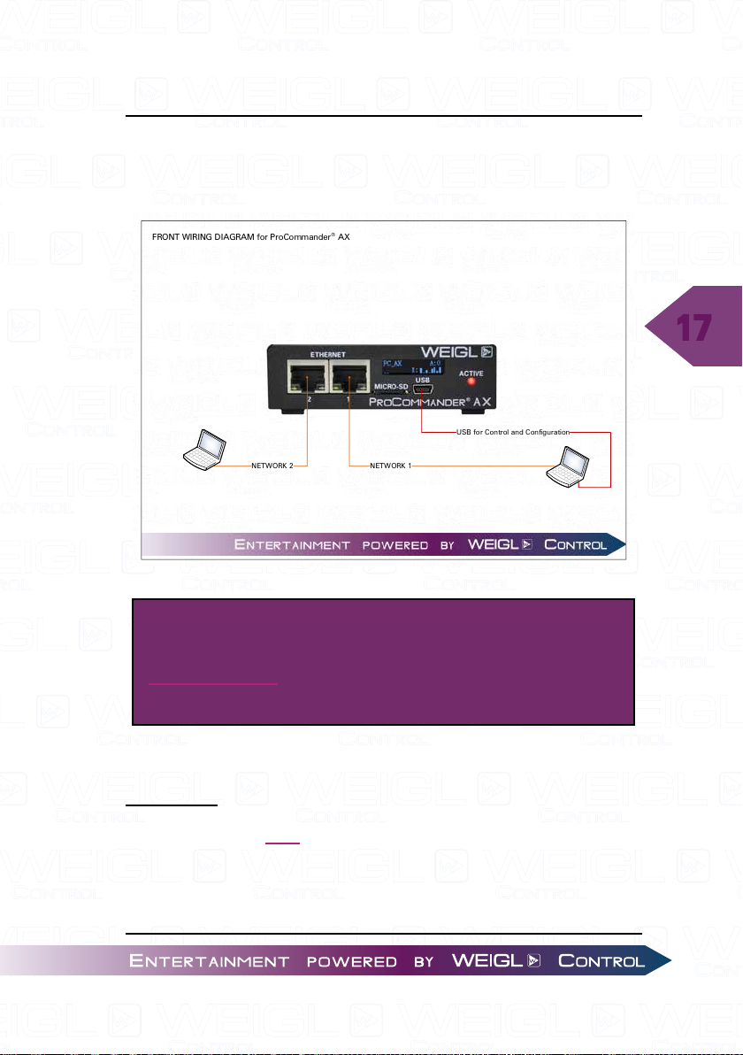
ProCommander® AX Pin Assignment
NETWORK 2
FRONT WIRING DIAGRAM for ProCommander® AX
USB fo r Control and C onfigurati on
NETWORK 1
3 ProCommander® AX Pin Assignment
3.1 ProCommander® AX FRONT
17
ATTENTION!
For a higher resolution, please download the
wiring diagram from Weigl Support and Solutions
Center.
3.1.1 Pin assignment FRONT
NETWORK
The network port 1 and 2 can be used for programming
and configuration. Network port 1 and 2 operates as a fixed-
IP address, UDP/ TCP Ethernet connection primarily supporting
IPV4 type communications. You can configure both the required
Page 18
ProCommander® AX Pin Assignment
fixed IP address, as well as the subnet mask through network
or USB messages. Additional enterprise settings available on
request and in the ASCII list.
USB
18
Using the USB port you can configure the ProCommander
®
AX. Please make sure that you have installed the applicable
driver for RS-232 support to use the USB port in conjunction with
either the Weigl Hardware Configurator or a terminal program
of your choice. You can download this stand-alone driver from
our website, as well as complete firmware packages inclusive
of these tools. Further information for installation you can find
here "USB – driver installation".
microSD
On the front panel of the ProCommander
®
AX is a slot for
storing a microSD for storing both logic, show and audio data.
Please switch OFF the unit before plug in or removing a microSD
card.
ATTENTION!
Weigl highly recommends to use SLC NAND industrial
grade instead of MLC microSD cards. We also offer
SLC industrial grade memory cards, which we have
tested with our devices. Other cards need to be
tested in terms of speed.
To plug in the card, push the card until it is flush with the
front panel. To remove the card, press gently on top of the card
and then let the card go. It will be pushed out a few millimeters
Page 19
ProCommander® AX Pin Assignment
by the internal mechanism for easy removal.
ATTENTION!
Please ensure that you do not press too hard on
the card, otherwise the ejection mechanism can be
destroyed.
When the card is valid "Card detected" will be shown in
the display. You may also see "Control.ini", success or "OK",
messages, meaning that the data in your control.ini file is
correct. Only if you have a Control.ini file stored on your card.
Display
Please refer to the chapter "ProCommander
®
AX Display".
19
Page 20
20
Rel1
1N4007
D1
1
1
223
4
RELA Y 1
Rel1
1N4007
D1
1
1
223
4
RELA Y 4
4/8 Ohm
4/8 Ohm
LEFT +
LEFT -
RIGHT +
RIGHT -
DIGITAL IN 5
PS+: 12V-24V
DIGI TAL IN 6
DIGI TAL IN 7
DIGI TAL IN 8
max. 500mA/24V
max. 500mA/24V
ALWAYS MOUNT FL YBACK DIODE IN REVERSE
DIRECTIO N PARALLEL TO EACH INDUCTI VE LOAD!
GND
REAR WIRING DIAGRAM for P roCommander® AX
PS+: 12V-24V/ma x. 96Watt
PS: GND
EXTERNAL POWER SUPPLY +
EXTERNAL AUDIO-AMPLI FIER
ALWAYS TAKE CARE OF
POWER POLARITY!
RS485/ CAN
ANALOG OUT 1 ANALOG OUT 4
max. 10mA
0-10V
ANALOG IN 1
(0-10V)
ANALOG IN 1/
DIGI TAL IN 1
ANALOG IN 2/
DIGI TAL IN 2
ANALOG IN 3/
DIGI TAL IN 3
ANALOG IN 4/
DIGI TAL IN 4
ANALOG IN 4
(0-10V)
max. 24V DC
INPUT CIRCUIT IN1-IN4
IN1-IN4
4K7
R2
10K
R1
D1
ZD3V3
2
1
1
1
2
2
TO_IN1-4
INPUT CIRCUIT IN1-IN4
IN1-IN4
4K7
R2
10K
R1
D1
ZD3V3
2
1
1
1
2
2
TO_IN1-4
The pin assignment
of the IX connector
can be found on a
separate page in this
wiring diagram!
ATTENTION!
IX Connector Type A
ProCommander® AX Pin Assignment
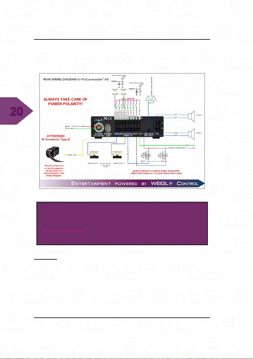
3.2 ProCommander® AX REAR
3.2.1 Pin assignment REAR
ATTENTION!
For a higher resolution, please download the
wiring diagram from Weigl Support and Solutions
Center.
POWER
The ProCommander
from 12V to 24V/ max. 96Watt (for class-2 installations).
®
AX can be operated with voltages
Page 21
ProCommander® AX Pin Assignment
ATTENTION!
The 24V may not be exceeded in any case. Thus,
if the power supply has a ripple in the voltage, the
peak voltage must not exceed 24V.
ANALOG IN 1-4/ DIGITAL IN 1-8
The ProCommander
®
AX has four analog and eight digital
inputs for connecting external dry contacts for the purpose of
logic evaluations or show starts. Inputs 1-4 are analog inputs,
which can evaluate voltages from 0-10V with a 12-bit resolution.
The query of the inputs is also available via the "GET" commands
(see ASCII chart).
A level change of individual inputs can trigger show starts,
if shows are stored on a microSD card. The assignment of the
shows to the different inputs can be defined in the Control.ini
file. Please refer to chapter "Control.ini" for more information.
ANALOG 1-4 (0-10V Output)
The ProCommander
®
AX has four 0-10V analog outputs
with a 12-bit resolution are available. The maximum current per
output is 10mA. Additional output current available from our
Pro I/OTM Analog 8.
DIGITAL OUT 5-8/ PWM 5-8
The ProCommander
®
AX has four digital open collector
outputs. Outputs 5-8 can be utilized additionally as PWM
outputs. Switching to PWM output is done automatically by the
ProCommander® AX, as soon as the channel is controlled by
21
Page 22
22
ProCommander® AX Pin Assignment
the control software with an analog- or an ASCII-command. The
PWM resolution is 12-bit.
If inductive loads (relays, solenoids, etc.) are connected, it
is essential to ensure that a free-wheeling diode is mounted
parallel to the load in the reverse direction (see diagram).
Otherwise the output drivers are destroyed. The common
cathode of the internal free-wheeling diodes is brought out on
pin 9 of the upper plug DIGITAL IN. Thus, if the internal free-
wheeling diodes are to be used, this must be connected to the
positive terminal of the external power supply.
ATTENTION!
The maximum current per output must not exceed
500mA. Do not use inbound power supplies of
higher than 24VDC.
LINE OUT
An external audio amplifier can be connected to the line-out
outputs of the ProCommander
®
AX. A parallel operation with
the internal amplifier is possible under certain conditions, and
depends on the connected external amplifier. If necessary, the
function must be independently tested and verified.
LS-OUT
The ProCommander
®
AX has a built in 2x20W Class D
amplifier. At the two outputs LS-L (left channel) and LS-R (right
channel), either 4-ohm or 8-ohm speakers may be connected.
Page 23
ProCommander® AX Pin Assignment
Rel1
1N4007
D1
1
1
223
4
RELAY 4
Rel1
1N4007
D1
1
1
223
4
RELAY 1
IN1-IN4
100NF/50V
C1
10K
R2
10K
R1
D1
ZPD5V1
2
1
1
1
1
2
2
2
TO_IN1-4
INPUT CIRCUIT IN1-IN4
4/8 Ohm
4/8 Ohm
LEFT +
LEFT -
RIGHT +
RIGHT -
DIGI TAL IN 5
PS+: 12V-24V
DIGI TAL IN 6
DIGI TAL IN 7
DIGI TAL IN 8
max. 500mA/24V
max. 500mA/24V
ALWAYS MOUNT FL YBACK DIODE IN REVERSE
DIRECTIO N PARALLEL TO EACH INDUCTI VE LOAD!
GND
REAR WIRING DIAGRAM for P roCommander® AX Gecko
PS+: 12V-24V/ma x. 96Watt
PS: GND
EXTERNAL POWER SUPPLY +
max. 24V DC
GND
PS-OUT+: 12V-24V/max . 96 Wat t
CAN-LOW
CAN-HIGH
EXTERNAL AUDIO-AMPLI FIER
ALWAYS TAKE CARE OF POWER
POLA RITY!
GND
PS-OUT+: 12V-24V/max . 96 Wat t
RS485 -
RS485 +
The pin assignment of the
IX connector can be found
on a separate page in this
wiring diagram!
RS485/ CAN
ATTENTION!
IX Connector Type A
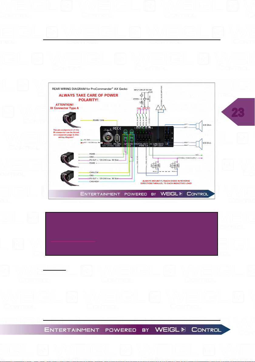
3.3 ProCommander® AX REAR Gecko (Vendor
specific, special order)
3.3.1 Pin assignment REAR Gecko
23
ATTENTION!
For a higher resolution, please download the
wiring diagram from Weigl Support and Solutions
Center.
POWER
The ProCommander
from 12V to 24V/ max. 96 Watt (Class-2 compliant).
®
AX can be operated with voltages
Page 24
ProCommander® AX Pin Assignment
ATTENTION!
The 24V may not be exceeded in any case. Thus,
if the power supply has a ripple in the voltage, the
peak voltage must not exceed 24V.
DIGITAL IN 1-4
24
The ProCommander
®
AX has 4 inputs for connecting external
dry contacts for the purpose of logic evaluations or show
starts. The query of the inputs is also available via the "GET"
commands (see ASCII chart), via UDP or external connections.
A level change of individual inputs can trigger shows, if they
are stored on a microSD card. The assignment of the shows to
the different inputs can be defined in the Control.ini file. Please
refer to chapter "Control.ini" for more information. Inputs can
be normally closed (NC), normally open (NO) or toggle.
DIGITAL OUT 1-4
The ProCommander
®
AX has four digital open collector
outputs.
If inductive loads (relays, solenoids, etc.) are connected, it
is essential to ensure that a free-wheeling diode is mounted
parallel to the load in the reverse direction (see diagram).
Otherwise the output drivers may be damaged. The common
cathode of the internal free-wheeling diodes is brought out on
pin 5 of the upper plug DIGITAL IN. Thus, if the internal free-
wheeling diodes are to be used, this must be connected to the
positive terminal of the external power supply.
Page 25
ProCommander® AX Pin Assignment
ATTENTION!
The maximum current per output must not exceed
500mA. Do not use inbound power supplies of
higher than 24VDC.
LINE OUT
An external audio amplifier can be connected to the line-out
outputs of the ProCommander
®
AX. A parallel operation with
the internal amplifier is possible under certain conditions, and
depends on the connected external amplifier. If necessary, the
function must be proven if it works properly.
LS-OUT
The ProCommander
®
AX has a built in 2x20W Class D
amplifier. At the two outputs LS-L (left channel) and LS-R (right
channel), either 4-ohm or 8-ohm speakers may be connected.
25
Page 26
26
ProCommander® AX Pin Assignment
3.4 ProCommander® AX Display
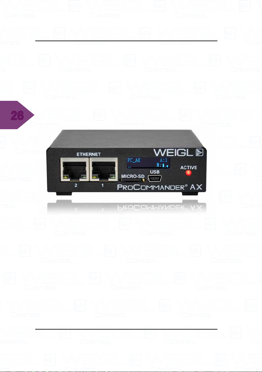
3.4.1 ProCommander® AX Outputs
The information of the motor outputs is located in the bottom
right section of the ProCommander® AX display. After the "M:"
the current status of each channel is displayed on the screen.
In this example only three outputs are displayed, channel one
to three.
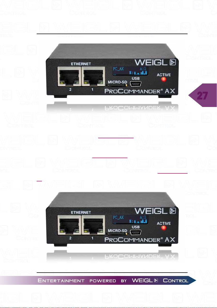
With the command !amm8# (RS-485 motors) or !acn8#
(CAN motors) eight outputs will be shown on the display.
This command can be send via the command line of the Weigl
Configurator. The ProCommander® AX display looks like this:
Page 27
ProCommander® AX Pin Assignment
:
3.4.2 ProCommander® AX Sub-Device-ID
The information of the Sub-Device-ID is located in the upper
right section of the ProCommander® AX display with "A:1".
In this example the Sub-Device-ID is 1. This means, that in
this case the ProCommander
OTM module from another ProCommander® via the Sub-Device-
ID 1.
®
AX can be addressed like a Pro I/
27
Page 28
28
ProCommander® AX Pin Assignment
The network connection of the other ProCommander® has
to be modified as well, please refer to the instruction manual of
the other ProCommander®. Detailed information can be found
in chapter 14 "Network connection between ProCommander®
and Pro I/O" in every ProCommander® instruction manual.
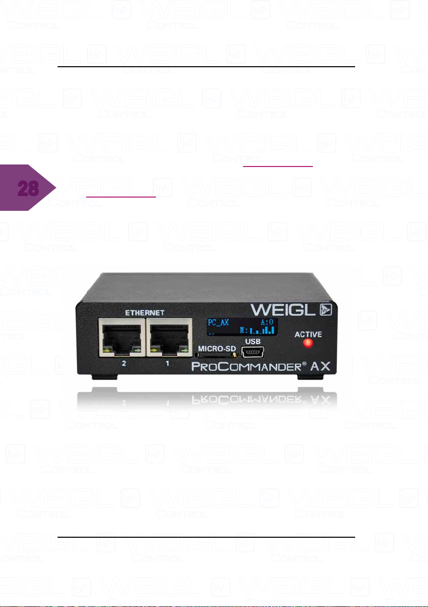
With the command !ssid0# the Sub-Device-ID can be
changed to 0 in the command line of the Weigl Configurator.
If the Sub-Device-ID is set to 0, then the ProCommander
®
AX
behaves like a typical ProCommander®, which can only be
addressed through the IP address and port number.
The ProCommander
®
AX display looks like this:
3.4.3 ProCommander® AX Loudspeaker
The information of the current volume of the audio is located
in the bottom left section of the ProCommander® AX display. It
is displayed with two bars corresponding to the current volume
of the audio file.
Page 29
ProCommander® AX Update
4 ProCommander®AX Update
4.1 ProCommander® AX Firmware Update
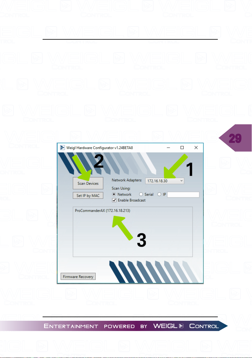
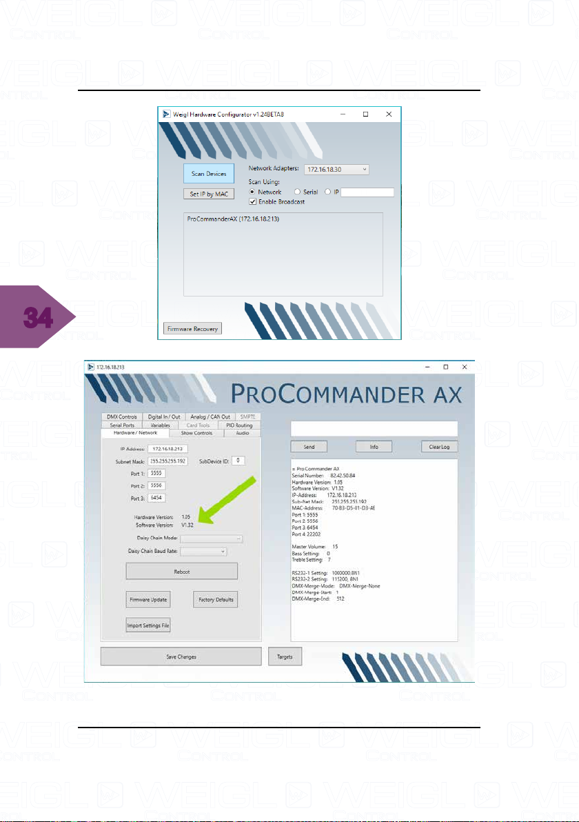
For the Firmware Update use Configurator v1.24BETA8 or
newer for PC, MAC users are auto updated.
Connect your computer with the ProCommander
Ethernet jack 1 via an Ethernet cable.
Select the correct network, then scan for devices and select
the ProCommander
®
AX with a double click.
®
AX
29
Page 30
30
ProCommander® AX Update
Select the button "Firmware Update" and then in the pop up
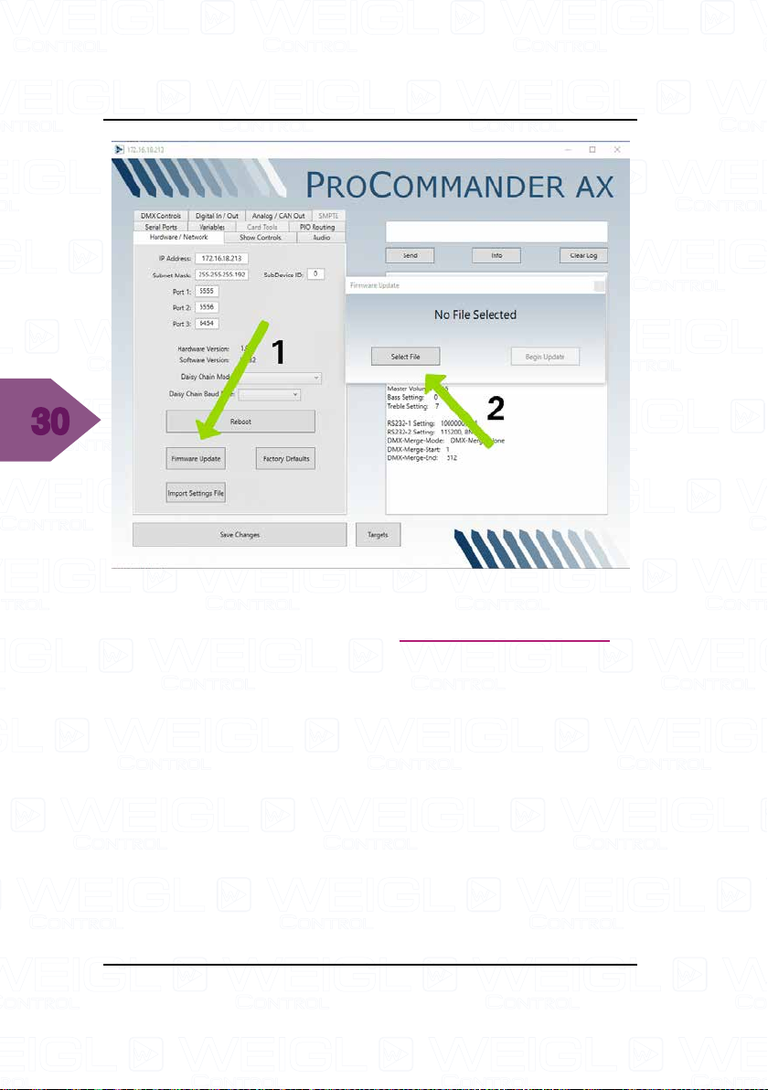
window "Select File". Choose the latest Firmware Update. In
this example it is Firmware Version BETA V132.bin.
Page 31
ProCommander® AX Update
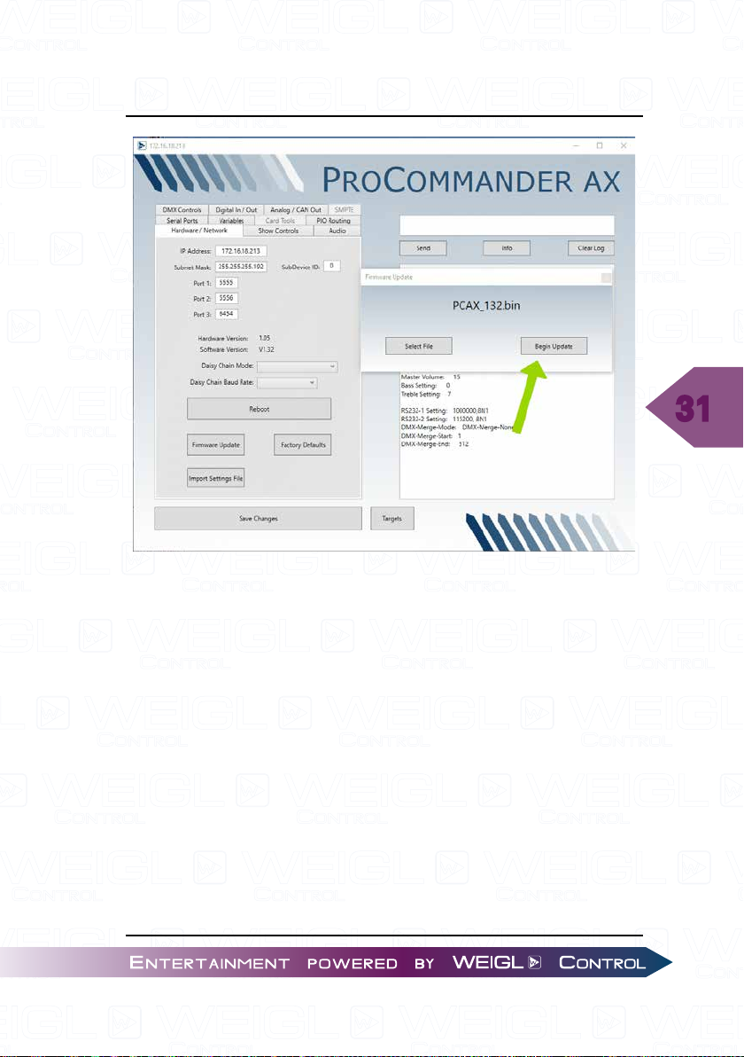
Start the update process with the button "Begin Update".
31
As soon as you can see the pop up window with "The firmware
update completed successfully." your ProCommander
ready.
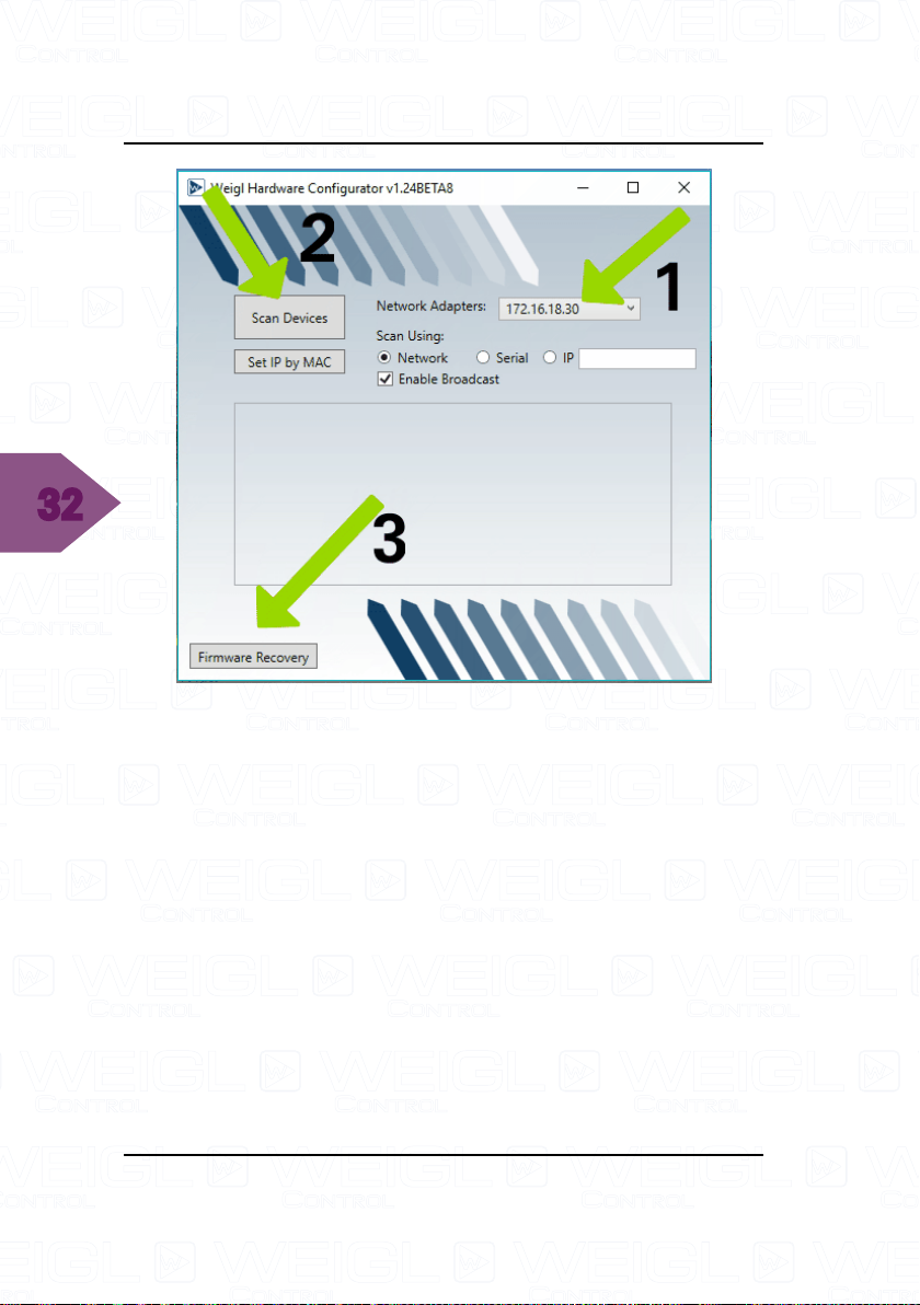
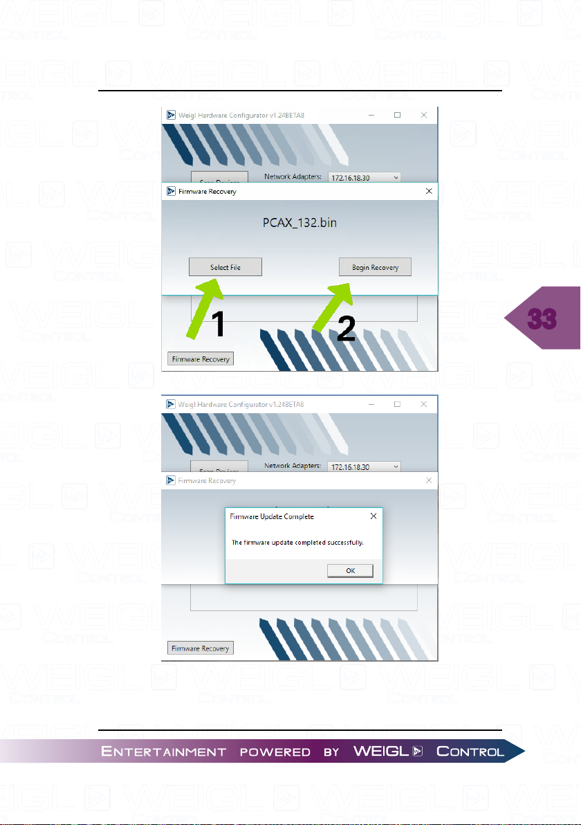
Please follow the following steps, if you see a looping display:
Reopen the Configurator, select your network and scan for
devices. No device will be listed. Press the button "Firmware
Recovery".
®
AX is
Page 32
32
ProCommander® AX Update
Press the button "Select File". Afterwards select the latest
firmware update and start the firmware update with the button
"Begin Recovery".
Page 33
ProCommander® AX Update
33
Page 34
34
ProCommander® AX Update
Page 35
ProCommander® AX Update
4.2 Wi-Fi Module Firmware Update
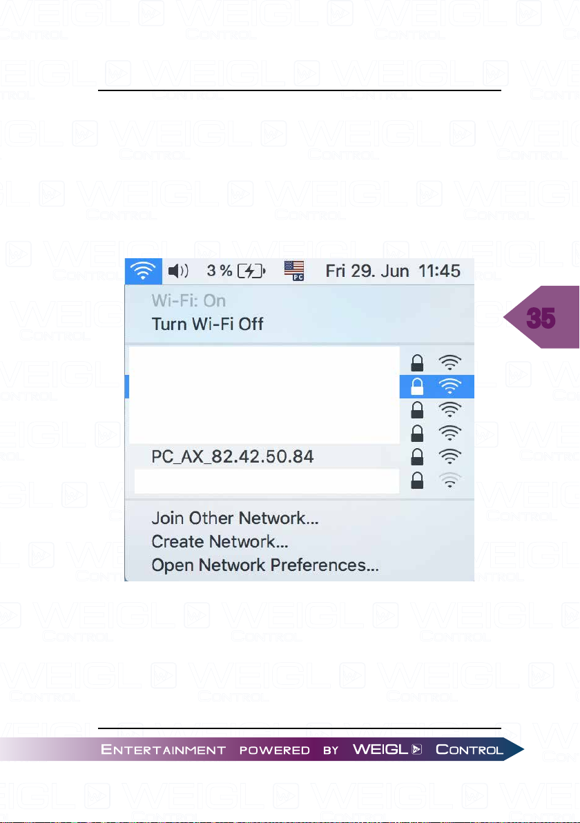
For updating the firmware of the Wi-Fi module of a
ProCommander® AX follow these steps:
Scan for the ProCommander
ProCommander® AX with the Serial number 82.42.50.84, so the
SSID of the ProCommander® AX looks like this:
®
AX. In this example it is the
35
Page 36
36
ProCommander® AX Update
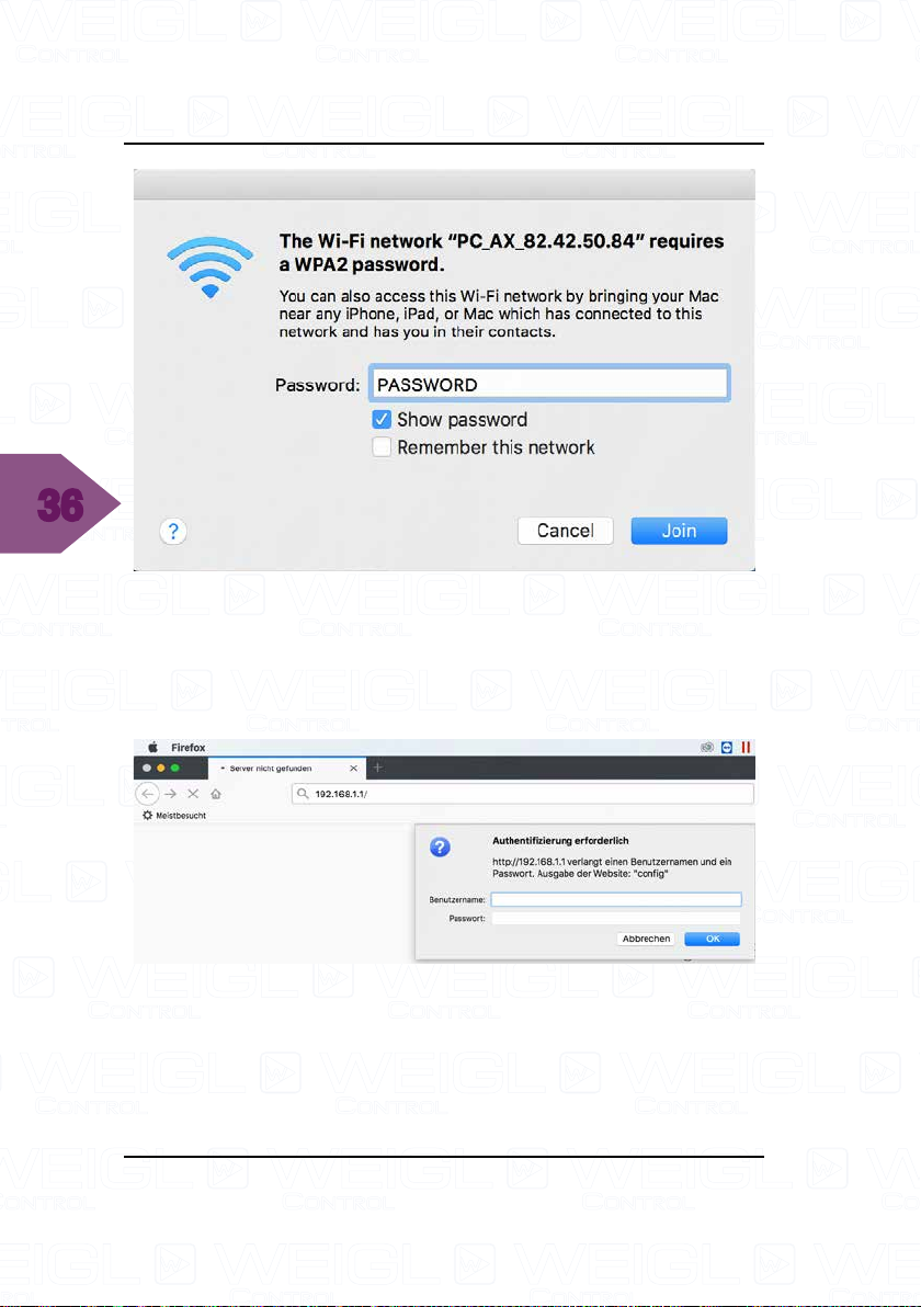
Enter "PASSWORD" as Password and confirm with "Join"
or "OK".
Open a web browser and type 192.168.1.1 in the URL.
Enter as username "admin" and as password "PASSWORD".
Page 37
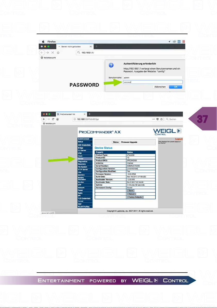
Select the menu tab "Device".
ProCommander® AX Update
37
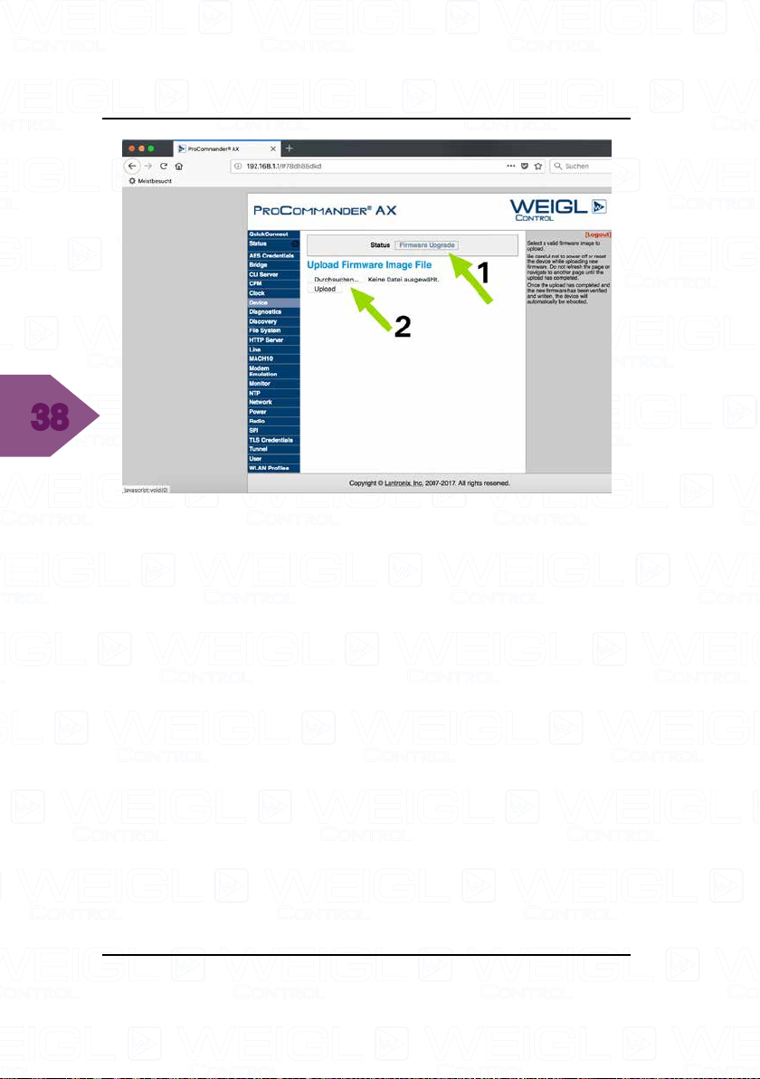
Select the button "Firmware Upgrade" and then the button
"choose".
Page 38
38
ProCommander® AX Update
Select the latest Wi-Fi module firmware update, in this
example it is xPico200_1.7.01R7.singed.rom. Afterwards press
the button "Upload".
Page 39
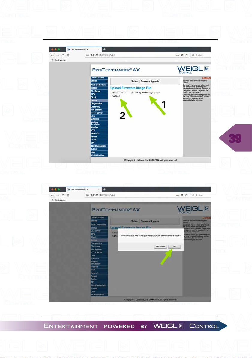
Confirm the alert with "OK".
ProCommander® AX Update
39
Page 40
40
ProCommander® AX Update
Page 41
ProCommander® AX Update
41
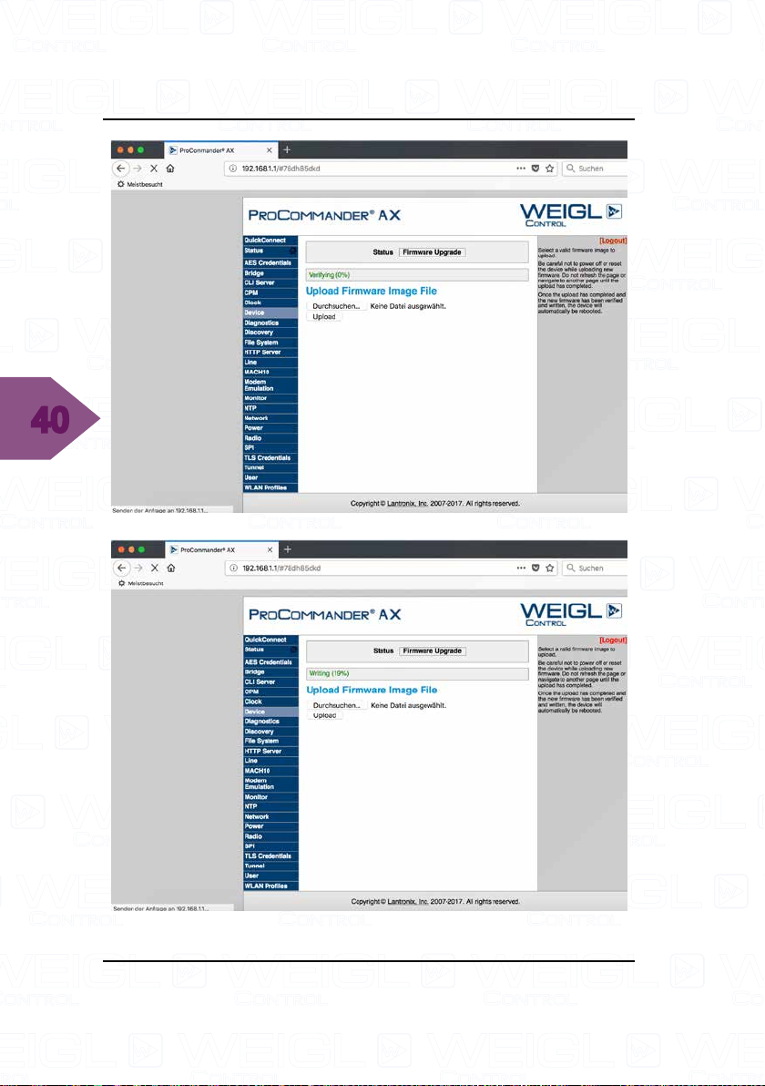
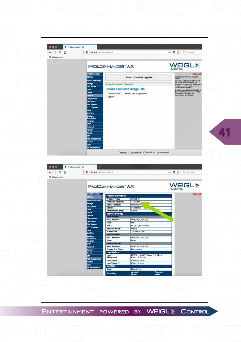
Check the firmware version in the menu tab "Status". You
may have to reconnect first after the update.
Page 42
42
ProCommander® AX Update
Page 43
ProCommander® AX Wi-Fi Configuration
5 ProCommander®AX Wi-Fi Configuration
The configuration of the ProCommander® AX Wi-Fi is
similar to the setup of a typical IOT device. First connect to the
ProCommander® AX setup SSID and then add our preferred
WLAN to the other WLAN profiles. Up to five WLAN profiles
can be stored in a Wi-Fi module of a ProCommander® AX.
5.1 Setup Wi-Fi Configuration
For configuration of the Wi-Fi settings you can use the
ProCommander® AX Wi-Fi web interface. Therefore you
have to connect the ProCommander® AX via Wi-Fi with your
computer, scan for the "ProCommander_AX" Wi-Fi, which is
by default a combination of "PC_AX" and the serial number
of your ProCommander® AX, which can be found on the label
underneath the device or via the Weigl Configurator in the line
"Serial Number: XX.XX.XX.XX". The password is "PASSWORD"
by default. After establishing a Wi-Fi connection, open up a web
browser and type "192.168.1.1" into the URL.
43
The username is "admin" and the password is "PASSWORD"
by default.
Page 44
44
ProCommander® AX Wi-Fi Configuration
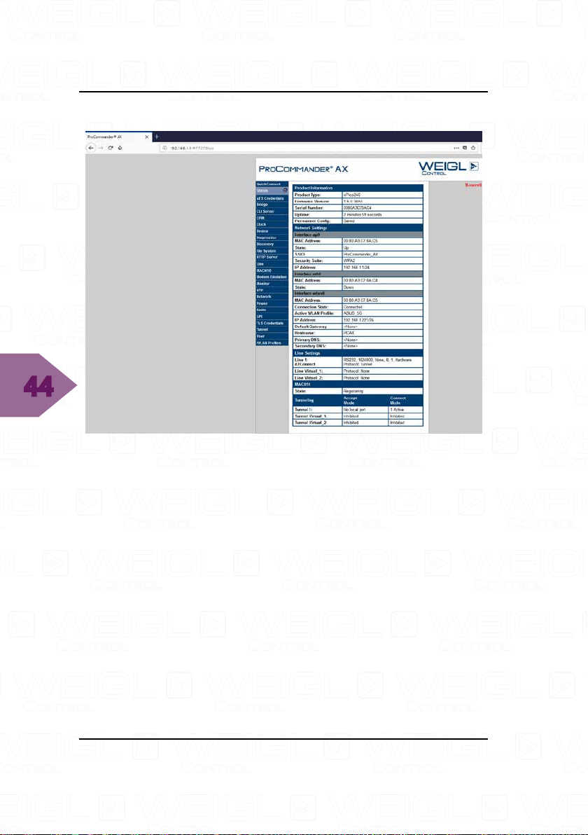
You should see the following:
Page 45
ProCommander® AX Wi-Fi Configuration
5.2 Network Configuration
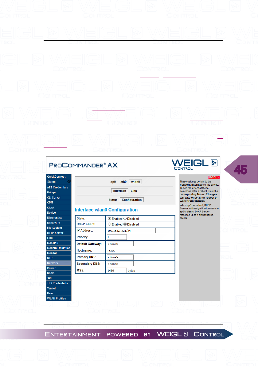
5.2.1 WLAN IP Address Configuration
If you want to change the WLAN IP address of your
ProCommander® AX activate "Network" in the left menu bar.
Select "wlan0" -> "Interface" -> "Configuration".
Through this IP address the ProCommander
controlled via Wi-Fi access points. Change the IP address
accordingly to your network. Afterwards save the changes with
"Submit", after a power cycle of the ProCommander® AX the IP
address is changed.
®
AX can be
45
Page 46
46
ProCommander® AX Wi-Fi Configuration
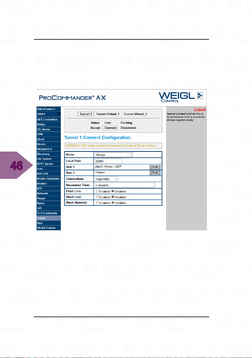
5.3 Tunnel Configuration
The default local port is "22202", if you want to change
it please select in the left menu "Tunnel" -> "Tunnel1" ->
"Connect" and change the local port as you wish.
Page 47
ProCommander® AX Wi-Fi Configuration
5.4 WLAN Profile Configuration
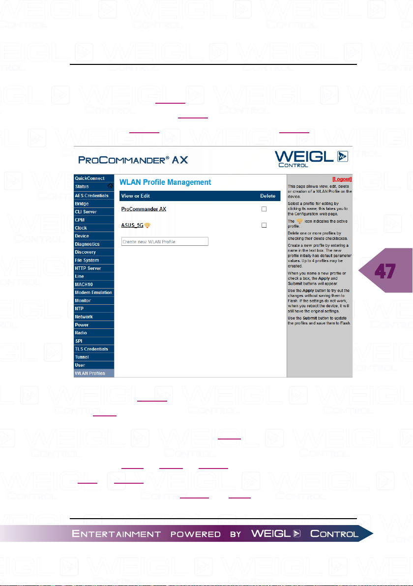
To add a new WLAN profile to your ProCommander® AX
select in the left menu "WLAN Profiles" and type in the text file
"Create new WLAN Profile" the name of your WLAN.
47
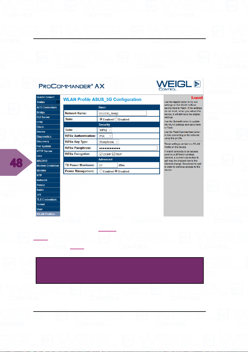
Select your WLAN and change all the settings accordingly to
your Wi-Fi network.
Type in the network name (SSID) into the field "Network
Name". Choose your security preference such as "Suite"
("NONE", "WEP", "WPA", "WPA2"), "WPAx Authentification"
("PSK", "8021X"), "WPAx Key Type" ("Passphrase", "Hex"),
"WPAx Encryption" ("CCMP", "TKIP") and type in your
password in the "WPAx Passphrase" field.
Page 48
48
ProCommander® AX Wi-Fi Configuration
Next select "Submit" to save it permanently.
Please be patient, this procedure takes a couple of minutes
until it is finished.
As soon as the new WLAN profile is saved you can use this
Wi-Fi connection to control the ProCommander® AX, even if it
has a hidden SSID.
ATTENTION!
Please be patient during the connection process.
Page 49
Analog MIN- and MAX-value
6 Analog MIN- and MAX-value
For each of the four 0-10V analog-channels, the four servo-
channels, as well as for the four PWM-channels a minimum and
maximum value can be adjusted.
So the voltage range, servohub or the PWM-value can be
circumscribed. Hereby, it is important to consider that after the
start-up all four analog-values have the voltage level 0V. The
eventually adjusted minimum value will be set at the output
immediately after the booting of the ProCommander® AX. This
takes a few milliseconds.
!san…# is the command for the minimum level. The
resolution of values is in 0.01%-steps from 0 to 10000. The
command !san1=1055# sets for the analog-channel 1 to a
minimum value of 10.55%. The minimum value must not be
higher than the maximum value. If a higher value will be entered
the minimum value will be set to the adjusted maximum value.
In this case, the analog-output remains at the adjusted value.
49
!sax…# adjust the maximum value, whereby the same
criteria as for the minimum value apply. The resolution is also in
0.01% steps from 0-10000 and the maximum value must not be
less than the minimal value. !sax2=9023# sets for the analog-
channel 2 the maximum value to 90.23%. The maximum value
must not be lower than the minimum value. If a lower value is
entered, the maximum value will be set to the level of minimum
value.
!qmm# lists all channels with their min and max values at
once.
Page 50
50
Analog MIN- and MAX-value
Page 51
Variable
7 Variable
With variables decisions can be made, conditional show
starts or counter can be realized.
Variables can be manipulated inside a show or through
external events. Possible actions are setting a value of a variable
or executing mathematical operations like add, subtract, multiply
or divide. A variable can also be loaded with the content of
another variable.
Basically there exist two types of variables, RAM-variables
and EEProm-variables. The RAM-variables are only valid during
the runtime of the device and lose their content after power off.
After power up, they are set to the value 0.
The EEProm-variable keeps their value also after power off.
Therefore, they can be used for example as a show-counter.
ATTENTION!
Although both types of variables may be handled
in the same way, RAM-variables should be used in
general, if there is no need of saving the content
after power off.
The variables are addressed by a number, where the numbers
1 to 70 refers to the 70 RAM-variables and the numbers 71 to
100 the 30 EEProm-variables.
51
Page 52
Variable
52
Page 53
Control.ini
8 Control.ini
The Control.ini file is a new and easy way to assign different
input events to any of the available ASCII-commands without
any special show programming. It is even possible to assign an
input event to several successive commands. An input event
may be a change of the remote inputs, a time event or a variable
change.
A level change of the remote inputs may be defined as
"close"-event (means activation of an input), "open"-event
(deactivation of an input) or "toggle"-event (every level change
at an input). With toggle, both the press and the release of a key
action will cause a trigger event.
If the device has resources to process the commands, all
functions of the ASCII-protocols are available. They have to
follow instantly the entry event. Further commands have to
start with the "!" exclamation mark. After the last command a
"#" hash tag has to be placed (see example).
The Control.ini file can be created with any text editor. After
completion, it should be copied into the main directory (root
directory) of the microSD card.
ATTENTION!
During execution there is no complex syntax check.
Therefore, the programmer is responsible for correct
command syntax.
53
Page 54
Control.ini
8.1 Structure of the Control.ini file
It must always start with the definition of the input event. As
a start condition either an "!i: Input events", "!t: Time events"
or "!v: Variable events" can be used.
ATTENTION!
The limit is one trigger event per line.
Only variable conditions can be combined in one
line. If you need a combination of several trigger
events you have to do this via variables.
8.1.1 !i: Input events
Event related to the digital inputs 1-8.
Example:
!i1c!...# -> if input 1 is activated (c=close), then the
downstream command will be executed.
54
!i1o!...# -> if input 1 is deactivated (o=open), then the
downstream command will be executed.
!i1t!...# -> if input 1 changes (t=toggle), then the
downstream command will be executed.
8.1.2 !t: Time events
The internal timer of the clock starts counting with zero
seconds, zero minutes and zero hours at the moment the device
is powered up. With insertion of the microSD-card, this clock is
also set to "0" zero.
Page 55
Control.ini
Each time value must be entered in the format
minutes:seconds. Hours must be converted to minutes. A time
of 2 hours, 15 minutes and 20 seconds should be formatted as
135:20.
The character after the "t" determines the way the time
should be interpreted.
m is the absolute time after powering on the ProCommander
AX or after the insertion of a microSD card. After each removal
or new insertion of the card the time is set to zero.
& means "modulo" which means, that any time the value is
reached the command is executed.
Example:
!tm01:20!…# -> if the time 1 minute 20 seconds is reached
after the start-up or plug in of the card, then the downstream
command will be executed.
!t&05:00!…# -> all 5 minutes the downstream command
will be executed.
®
8.1.3 !v: Variable events
For basic information about the variables read the chapter
"Variable".
After each change of a variable the Control.ini file is checked,
if an event is assigned to this variable.
55
If this variable condition is true, the following command will
be executed.
Page 56
56
Control.ini
Immediately after the input event, the command definition
has to follow.
Example:
!vcc1=1!...# -> if the variable 1 has the value 1, then the
downstream command will be executed.
You can assign several commands to an input event. In this
case, attach the additional commands. The total number of
characters of a command line must not exceed 150 characters.
ATTENTION!
AFTER EACH #-CHARACTER A NEW COMMAND
LINE HAVE TO BE BEGUN.
The following command combination cannot be
interpreted properly and therefore it will not be
executed correctly:
!i1c!rsn1#!i2c!rsn2#
The correct Control.ini looks like this:
!i1c!rsn1#
!i2c!rsn2#
Page 57
Control.ini
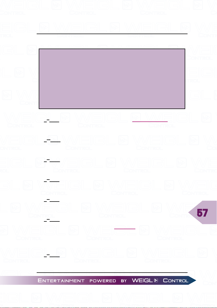
The content of the Control.ini file can look like this:
!i1c!ess1001#
!i3o!epf1%20<2.5#
!i4t!epl1_4%50#
!i5c!cfm0<5#
!i5o!cfm32<5#
!tm01:20!rsn:\SHOW\001_SHOW.WM1#
!t&05:00!rsn2#
1st line: If input 1 is closed (!i1c), the open collector outputs
1 and 4 will be activated (!ess1001).
nd
2
line: If input 3 is open (!i3o), then PWM output 1 fades
within 2.5 seconds to 20% (!epf1%20<2.5).
rd
3
line: With every level change of input 4 (!i4t), the PWM
value of outputs 1 to 4 are set to 50% (!epl1_4%50).
th
4
line: If input 5 is closed (!i5c), the volume fades to level 0
within 5 seconds (!cfm0<5).
th
5
line: If input 5 is open (!i5o), the volume fades in within 5
seconds to that value which is stored in EE-Prom (!cfm32<5).
th
6
line: At 1 minute and 20 seconds after switching on the
device or after insertion of the microSD card (!tm01:20), the
first show starts in normal mode (!rsn:\SHOW\001_SHOW.
WM1).
th
7
line: Every 5 minutes (!t&05:00) the second show starts
in normal mode (!rsn2).
57
Page 58
Control.ini
8.2 Case studies
8.2.1 Project 1 – The first show runs in a loop and
is interrupted by the second show every 45
minutes
The project consists of two show files. The first show (001_
SHOW.WM1) runs in a loop and is interrupted every 45 minutes
by the second show (002_SHOW.WM1). After the second show
ends, the first show restarts. This will be repeated till, the device
is turned off or the card is removed.
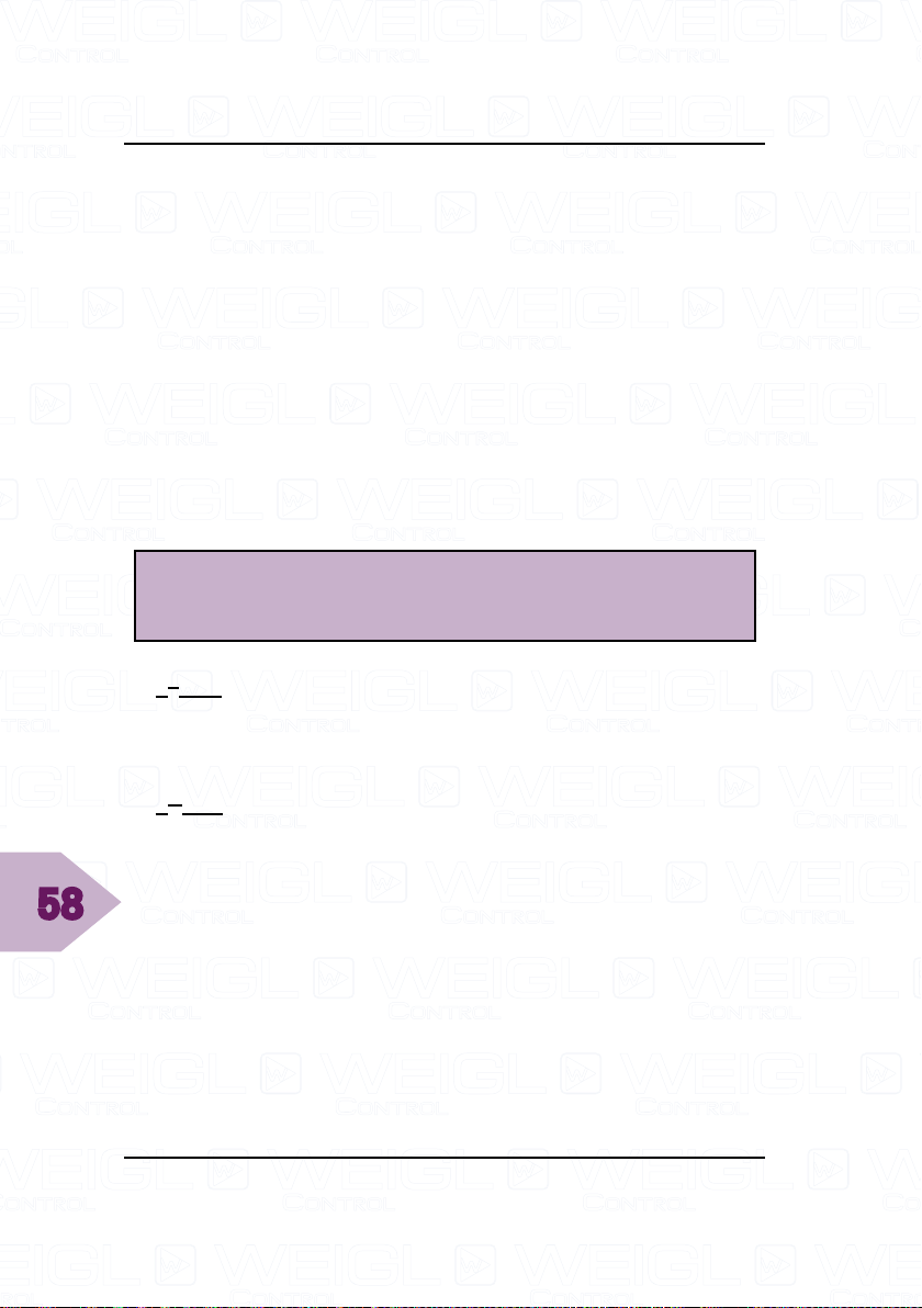
The content of the Control.ini file looks like this:
!tm00:00!rsnl1#
!t&45:00!vcc1=1!rst2#
1st line: At time 00:00, right after power up of the device or
insertion of the memory card (!tm00:00), the first show (001_
SHOW.WM1) will start in loop mode (!rsnl1).
58
nd
2
line: Because the command (!t&45:00#) is already true at
power up or insertion of the card, a variable !vmc1=1# needs
to be included in show 1. So every 45 minutes, this variable will
be checked, if the value is 1 (!vcc1=1). If the condition is true,
the second show will be started in terminate mode, i.e. all other
shows will be stopped. In this example the loop of show 1 is
interrupted. With a !rsa1# command at the end of the second
show, the first show starts again.
Page 59
Control.ini
8.2.2 Project 2 – Three switches trigger three shows
ATTENTION!
The limit for an input event is one per line.
Only variable conditions can be combined in one
line. If input combinations are needed it has to be
done via variables.
This project consists of three shows and is triggered with
three switches.
The first show should start, if switch 1 and 3 are closed and
switch 2 is open.
The seconds show should start, if switch 1 and 2 are closed
and switch 3 is open.
The third show should start, if switch 1 is open and switch 2
and 3 are closed.
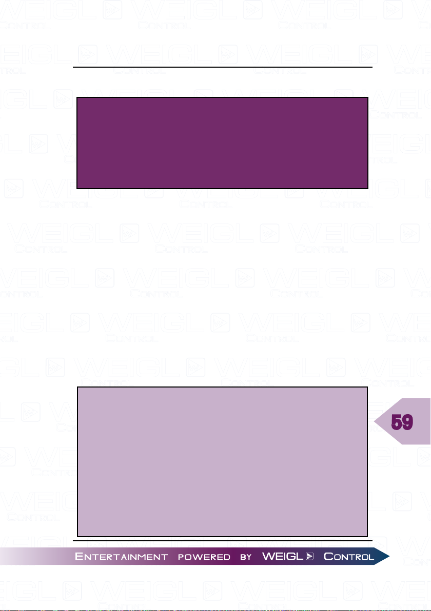
The content of the Control.ini file looks like this:
!i1c!vmc1=1#
!i1o!vmc1=0#
!i2c!vmc2=1#
!i2o!vmc2=0#
!i3c!vmc3=1#
!i3o!vmc3=0#
!vcc1=1!vcc2=0!vcc3=1!rsn1
!vcc1=1!vcc2=1!vcc3=0!rsn2
!vcc1=0!vcc2=1!vcc3=1!rsn3
59
Page 60
Control.ini
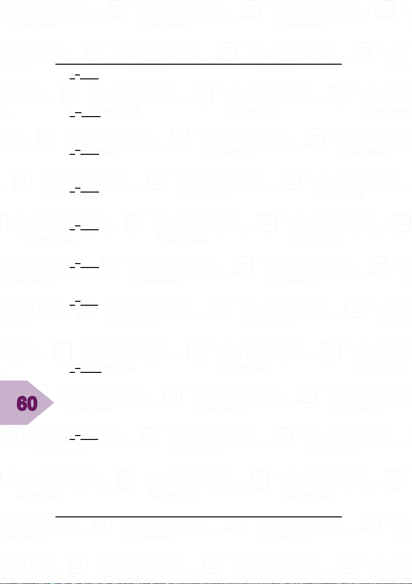
1st line: If input 1 is closed (!i1c), then the value of variable 1
will attain 1 (!vmc1=1).
nd
2
line: If input 1 is open (!i1o), then the value of variable 1
will attain 0 (!vmc1=0).
rd
3
line: If input 2 is closed (!i2c), then the value of variable 2
will attain 1 (!vmc2=1).
th
4
line: If input 2 is open (!i2o), then the value of variable 2
will attain 0 (!vmc2=0).
th
5
line: If input 3 is closed (!i3c), then the value of variable 3
will attain 1 (!vmc3=1).
th
6
line: If input 3 is open (!i3o), then the value of variable 3
will attain 0 (!vmc3=0).
th
7
line: If variable 1 gets the value 1 (!vcc1=1), the variable 2
the value 0 (!vcc2=0) and the variable 3 the value 1 (!vcc3=1),
then the first show (001_SHOW.WM1) will start in normal mode
(!rsn1).
60
th
8
line: If variable 1 and 2 gets the value 1 (!vcc1=1)
(!vcc2=1) and the variable 3 the value 0 (!vcc3=0), then the
second show (002_SHOW.WM1) will start in normal mode
(!rsn2).
th
9
line: If variable 1 gets the value 0 (!vcc1=0), the variable 2
the value 1 (!vcc2=1) and the variable 3 the value 1 (!vcc3=1),
then the third show (003_SHOW.WM1) will start in normal mode
(!rsn3).
Page 61
Control.ini
8.2.3 Project 3 – One area has to be filled with four
different recorded voice sounds
The project has one area. The area can be filled with four
different recorded voice sounds, which are German, Spanish,
French and English. The languages can be changed with a
rotary switch. So four shows have to be created.
The area is activated with switch 1. The pins of the rotary
switch are assigned to pin 2-5.
The content of the Control.ini file looks like this:
!i2c!vmc1=1#
!i3c!vmc1=2#
!i4c!vmc1=3#
!i5c!vmc1=0#
!i1c!vcc1=1!rsn1#
!i1c!vcc1=2!rsn2#
!i1c!vcc1=3!rsn3#
!i1c!vcc1=0!rsn4#
1st line: If input 2 is activated (!i2c), then the value of variable
1 will attain 1 (!vmc1=1).
nd
2
line: If input 3 is activated (!i3c), then the value of variable
1 will attain 2 (!vmc1=2).
rd
3
line: If input 4 is activated (!i4c), then the value of variable
1 will attain 3 (!vmc1=3).
th
4
line: If input 5 is activated (!i5c), then the value of variable
1 will attain 0 (!vmc1=0).
61
Page 62
Control.ini
5th line: If input 1 is activated (!i1c) and the value of variable
1 is equal 1 (!vcc1=1), then the first show (001_SHOW.WM1)
will start (!rsn1). In this case the show is in German.
th
6
line: If input 1 is activated (!i1c) and the value of variable 1
is equal 2 (!vcc1=2), then the second show (002_SHOW.WM1)
will start (!rsn2). In this case the show is in Spanish.
th
7
line: If input 1 is activated (!i1c) and the value of variable
1 is equal 3 (!vcc1=3), then the third show (003_SHOW.WM1)
will start (!rsn3). In this case the show is in French.
th
8
line: If input 1 is activated (!i1c) and the value of variable
1 is equal 0 (!vcc1=0), then the fourth show (004_SHOW.WM1)
will start (!rsn4). In this case the show is in English.
62
Page 63
Control.ini
8.2.4 Project 4 – External control of a VU-meter
display
The project consists of one show, which is triggered by
each contact closure via input 1. Therefore the restart mode is
required.
In show 1 there are four variable decrement commands
(!vmc-1#) with a time gap of one second. If LEDs are connected
on the digital outputs, each time the button is activated another
LED is illuminated similar to a VU-meter display. If the button
isn't activated, the variable will be decremented by the variable
commands in the show and the LEDs turn off.
The content of the Control.ini file looks like this:
!i1c!rsr1#
!i1c!vcc1<4!vmc1+1#
!vcc1=0!ess0000#
!vcc1=1!ess1000#
!vcc1=2!ess1100#
!vcc1=3!ess1110#
!vcc1=4!ess1111#
!vcc1=4!vmc1=0#
63
1st line: If input 1 is closed (!i1c), then the show 1 (001_
SHOW.WM1) will start in restart mode (!rsr1).
nd
2
line: Each time if input 1 is activated (!i1c) and the variable
1 is less than 4 (!vcc1<4), then the variable increments by one
(!vmc1+1).
Page 64
Control.ini
3rd line: If the value of variable 1 is equal 0 (!vcc1=0), then
the output 1 to 4 will be cleared (!ess0000).
th
4
line: If the value of variable 1 is equal 1 (!vcc1=1), then
the output 1 will be activated and output 2 to 4 will be cleared
(!ess1000).
th
5
line: If the value of variable 1 is equal 2 (!vcc1=2), then
the output 1 and 2 will be activated and output 3 to 4 will be
cleared (!ess1100).
th
6
line: If the value of variable 1 is equal 3 (!vcc1=3), then
the output 1 to 3 will be activated and output 4 will be cleared
(!ess1110).
th
7
line: If the value of variable 1 is equal 4 (!vcc1=4), then
the all four outputs will be activated (!ess1111).
th
8
line: If the value of variable 1 is equal 4 (!vcc1=4), then
the value of variable 1 will be set to zero (!vmc1=0).
64
Page 65
Control.ini
8.2.5 Project 5 – One pushbutton controls five shows
This project consists of five shows, which are controlled by
one pushbutton. After each actuation of the pushbutton a new
show is started.
Therefore the command !vmc1=X# has to be inserted
at the end of each show, whereby the character X has to be
incremented in each show by one.
In this example the command !vmc1=1# will be inserted at
the end of the first show, !vmc1=2# at the end of the second
show, !vmc1=3# at the end of the third show and so on.
The content of the Control.ini file looks like this:
!tm00:10!vmc1=0#
!i1c!vcc1=0!rst1#
!i1c!vcc1=1!rst2#
!i1c!vcc1=2!rst3#
!i1c!vcc1=3!rst4#
!i1c!vcc1=4!rst5#
!vcc1=4!vmc1=0#
1st line: At 10 seconds after power on or inserting the
memory card (!tm00:10), the value of variable 1 will be set to
0 (!vmc1=0).
nd
2
line: If input 1 is closed (!i1c) and the value of variable 1
is equal 0 (!vcc1=0), then the first show (001_SHOW.WM1) will
start in restart mode (!rst1).
65
Page 66
Control.ini
3rd line: If input 1 is closed (!i1c) and the value of variable 1
is equal 1 (!vcc1=1), then the second show (002_SHOW.WM1)
will start in restart mode (!rst2).
th
4
line: If input 1 is closed (!i1c) and the value of variable 1 is
equal 2 (!vcc1=2), then the third show (003_SHOW.WM1) will
start in restart mode (!rst3).
th
5
line: If input 1 is closed (!i1c) and the value of variable 1
is equal 3 (!vcc1=3), then the fourth show (004_SHOW.WM1)
will start in restart mode (!rst4).
th
6
line: If input 1 is closed (!i1c) and the value of variable 1 is
equal 4 (!vcc1=4), then the first show (005_SHOW.WM1) will
start in restart mode (!rst5).
th
7
line: If the value of variable 1 is equal 4 (!vcc1=4),
then variable 1 will attain the value zero (!vmc1=0). If the
pushbutton is activated again the whole process will start from
the beginning.
66
ATTENTION!
If you want to learn more about how to write a
correct control.ini, please check also other case
studies on Weigl Support and Solutions Center.
Page 67
Folder structure of the Flash Card
9 Folder structure of the Flash Card
To begin shows, audio files, folder and file names have to
follow a predefined order.
Generally, only one subdirectory is supported.
All shows must therefore be in the folder "SHOWS". The first
three characters of the show name must have a number in the
range of 001-999. The remaining 5 characters do not matter.
Leading zeros in the range from 001-099 are required. The file
extension must be "WM1".
Example:
001_SHOW.WM1, 023_TEST.WM1, 320_PLAY.WM1
By using this order, remote access to the shows can be done
very easily just by number. This can be used for starting shows
within a show as well as for calling shows from outside by a
corresponding definition in the Control.ini file.
The same syntax applies to audio files. These must be stored
in the folder "AUDIO". The naming of the audio file is analogous
to the show files. The file name has to begin with a number
between 001 and 999 followed by any 5 other characters. The
file extension must an WAV audio format.
ATTENTION!
Weigl X Series devices support only the WAV audio
format.
67
Page 68
Folder structure of the Flash Card
68
Page 69
Programming the ProCommander® AX
10 Programming the ProCommander® AX
Due to the open interface protocol, there are various software
programs that support the ProCommander® AX.
Please refer to the manual of the respective software to learn
how to program the ProCommander
®
AX.
69
Page 70

Programming the ProCommander® AX
70
Page 71
Programming the ProCommander® AX
11 Network Connection Communication
11.1 Network Connection between
ProCommander® AX and Pro I/O
The ProCommander® AX commands an intern chart, which
associate each "Sub-Device-ID" of a Pro I/OTM module with an
IP address.
By default for all modules broadcast addresses are adjusted,
which read in all commands, independently of the adjusted
IP address of the Pro I/O
address adjustment (A1, A2, …) of a device, each Pro I/O
module analyze only the own commands.
If it's necessary to assign individual IP addresses, so that
conflicts with other devices in the network can be avoided, the
values of the charts can be modified.
Two commands are available for that. On the one hand the
global command !swi…# and on the other hand the individual
command !spi…#.
With !swi…# a consecutive numbering takes place for all
Pro I/O
TM
modules, beginning with the entered start-IP address.
With !spi…# each module can be assigned to an individual
address. These commands can be assigned via the configurator.
TM
modules. Because of the Sub-Net
TM
TM
71
!spp1=22202# sets the port of the Sub-Device-ID with the
ID 1 to 22202.
!gpo1# gets the port of the Sub-Device-ID 1.
Page 72
Programming the ProCommander® AX
72
ATTENTION!
If the communication between the ProCommander
and the Sub-Device is not working, please check the
intern chart, if all values of the IP address and port
of the Sub-Device are set correctly and correspond
to its Sub-Device-ID in the chart.
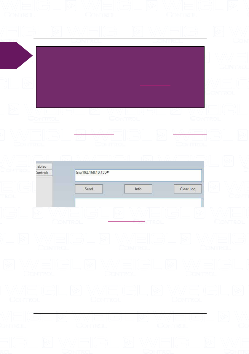
Example:
For the "Sub-Device-ID" address 1 the IP address
192.168.10.150# is chosen. The command reads as followed
!swi192.168.10.150#.
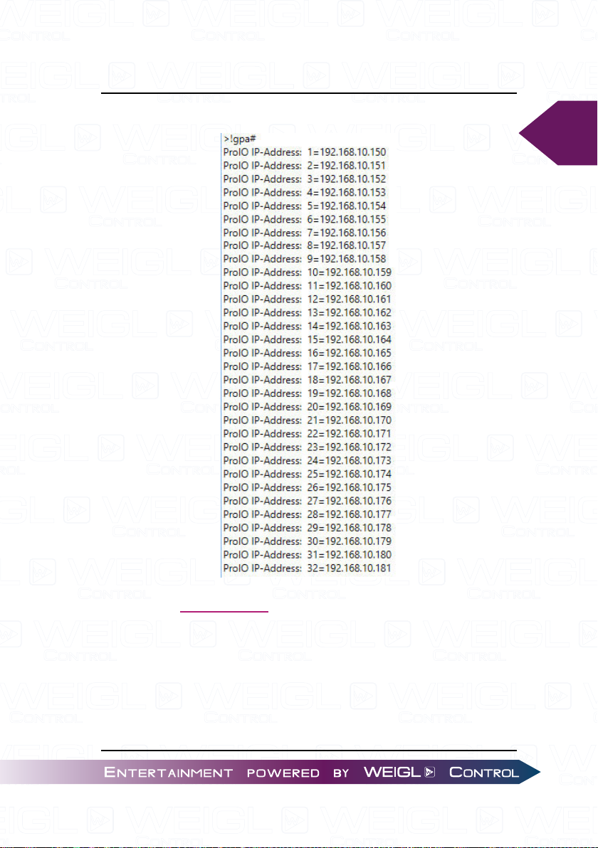
It assigns automatically IP addresses in ascending order for
all 32 possible modules on the ProCommander® AX. With the
command !gpa# the intern chart can be called.
®
Page 73
Programming the ProCommander® AX
In this case the result looks like this:
73
Now, all IP addresses of the Pro I/OTM modules have to be
modified in accordance with the chart above. So, module with
A1 on the display gets 192.168.10.150, with A2 on the display
gets 192.168.10.151 etc.
Page 74

Programming the ProCommander® AX
74
ATTENTION!
If in the same network two or multiple ProCommander
are in use, different IP addresses for all devices have
to be assigned for their Pro I/O
TM
modules.
Example:
For the second ProCommander
®
the first Pro I/OTM module
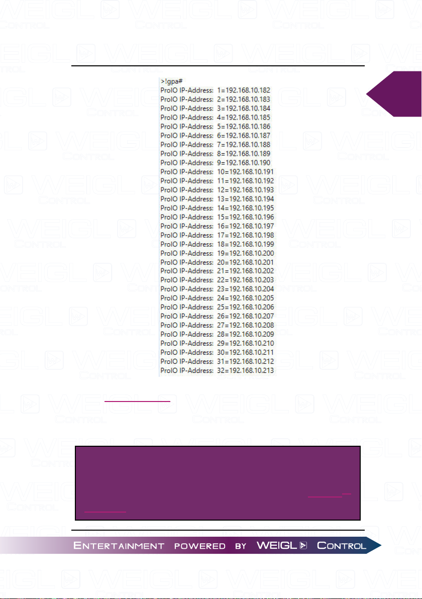
will be assigned with the IP address 192.168.10.182 with the
command !swi192.168.10.182#. With the command !gpa# the
intern chart will be called, these looks like this:
Page 75
Programming the ProCommander® AX
75
All IP addresses of the Pro I/OTM modules which are
connected with the second ProCommander® have to begin with
192.168.10.182.
ATTENTION!
More detailed information to configure a Pro I/O
module can be found in the manual for the Pro I/OTM
modules.
TM
Page 76
76
Programming the ProCommander® AX
11.2 Network Connection between
ProCommander® AX and another
ProCommander® AX
Instead of using a Pro I/OTM module as Sub-Device-ID
another ProCommander® AX can be used instead.
Therefore the Sub-Device-ID of the ProCommander
which should be controlled by another ProCommander® AX has
to be changed from 0, which means its in the ProCommander®
mode, to a Sub-Device-ID from 1 to 32, which means
the ProCommander® AX can be controlled by another
ProCommander® as it would be a Pro I/OTM module.
With the command !ssid1# the Sub-Device-ID can be
changed to 1 in the command line of the Weigl Configurator. In
the display the "A:0" will change to "A:1", for further information
on the display please refer to ProCommander® AX Display.
As soon as the ProCommander
mode the device can be controlled like a Pro I/OTM module through
the Sub-Device-ID network communication. Please refer to
Network Connection between ProCommander® AX and Pro I/
OTM for setting up a Sub-Device network communication.
®
AX left the ProCommander®
®
AX,
Page 77
ProCommander® AX Appendix
12 Appendix
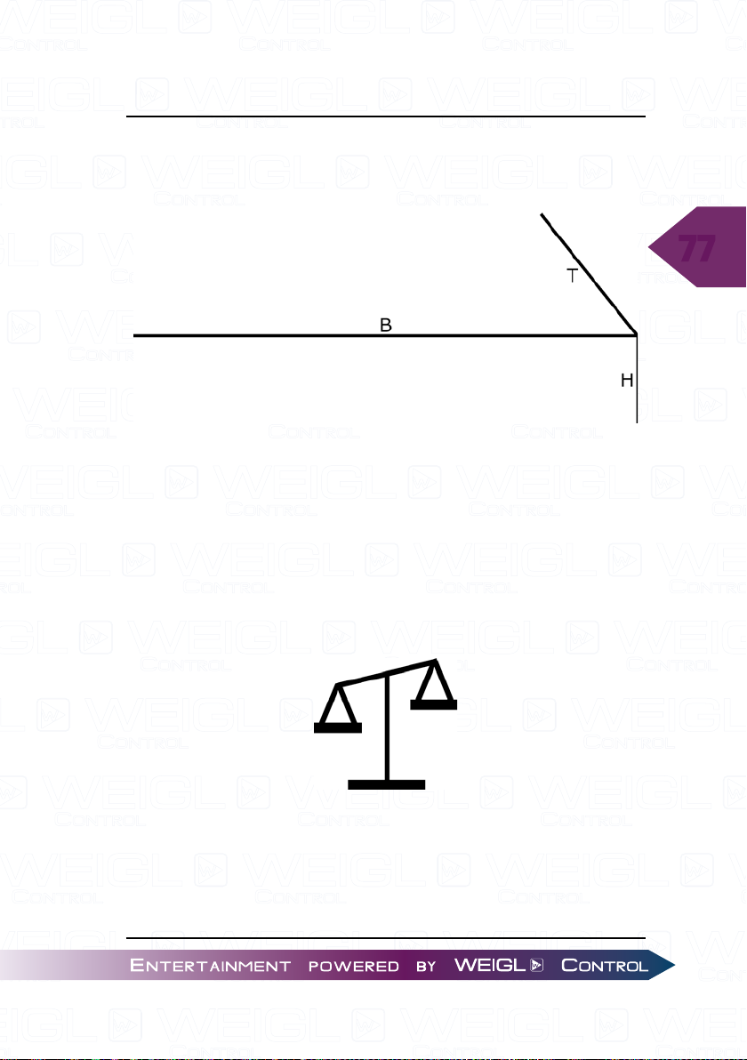
12.1 Measurements ALU Housing
H: 35 mm 1.38 in
B: 94 mm 3.70 in
T: 85 mm 3.35 in
(T= exclusive antenna)
77
0,19 kg 0.43 lb
Page 78
78
ProCommander® AX Appendix
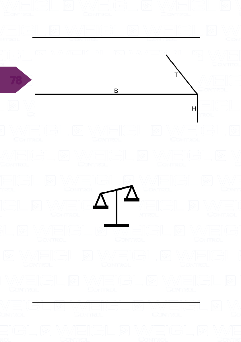
12.2 Measurements
H: 28 mm 1.10 in
B: 88 mm 3.46 in
T: 85 mm 3.35 in
0,13 kg 0.29 lb
Page 79
ProCommander® AX Appendix
12.3 Electrical and operating requirements
Surrounding temperature: -5°C to 50°C (23°F to 122°F)
Relative humidity: 0% to 90% non condensing
Operating altitude: tested up to 2.700m (9,000 ft)
ATTENTION!
Exceeding this limits will reduce the life time of the
product.
79
Page 80

ProCommander® AX Appendix
12.4 Wi-Fi Module Specification
12.4.1 Network
Wireless LAN Specifications
80
• IEEE 802.11 a/b/g up to 54 Mbps; 802.11 n (1x1) up to
150 Mbps
• 20 and 40 MHz channel width with optional SGI
• Dual Band 2.4 GHz and 5 GHz, Channels 1-13, UNII-1, 2a,
2e and 3
• Supports IEEE 802.11 d/h/i
12.4.2 Security & Authentication
• AES/ CCMP and TKIP encryption, WPA/ WPA2 Personal
• WPA2 Enterprise
12.4.3 Certifications & Compliance
• Type Approvals: USA (FCC Part 15), Canada (IC RSS),
EU (RED), Japan (MIC), China (SRRC), AU/NZS
• Safety: IEC 62368, EN 62368, EN 62311, UL 60950
• RoHS, REACH
Page 81
ProCommander® AX Appendix
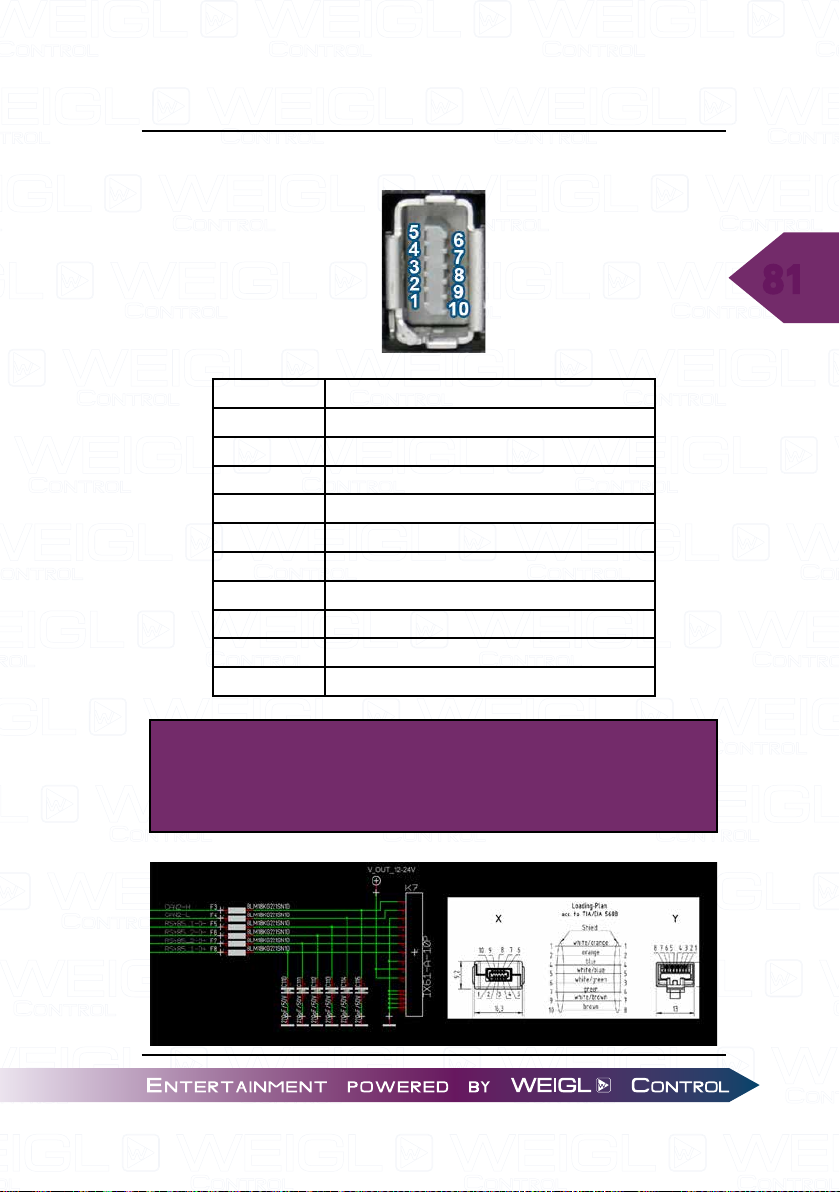
12.5 Pin assignment IX Connector - RS485/ CAN
Connector RS485/ CAN
Pin 1 CAN-HIGH
Pin 2 CAN-LOW
Pin 3 GND
Pin 4 RS485_1_D- / Servo-OUT (Dynamixel, ...)
Pin 5 RS485_2_D- / DMX-IN/DMX-OUT
Pin 6 RS485_2_D+/ DMX-IN/DMX-OUT
Pin 7 RS485_1_D+/ Servo-OUT (Dynamixel, ...)
Pin 8 GND
Pin 9 PS-OUT+: 12V-24V/max. 96 Watt
Pin 10 PS-OUT+: 12V-24V/max. 96 Watt
81
ATTENTION!
IX Connector Type A
Standardized cable for IX to RJ45 connector:
Page 82
82
ProCommander® AX Appendix
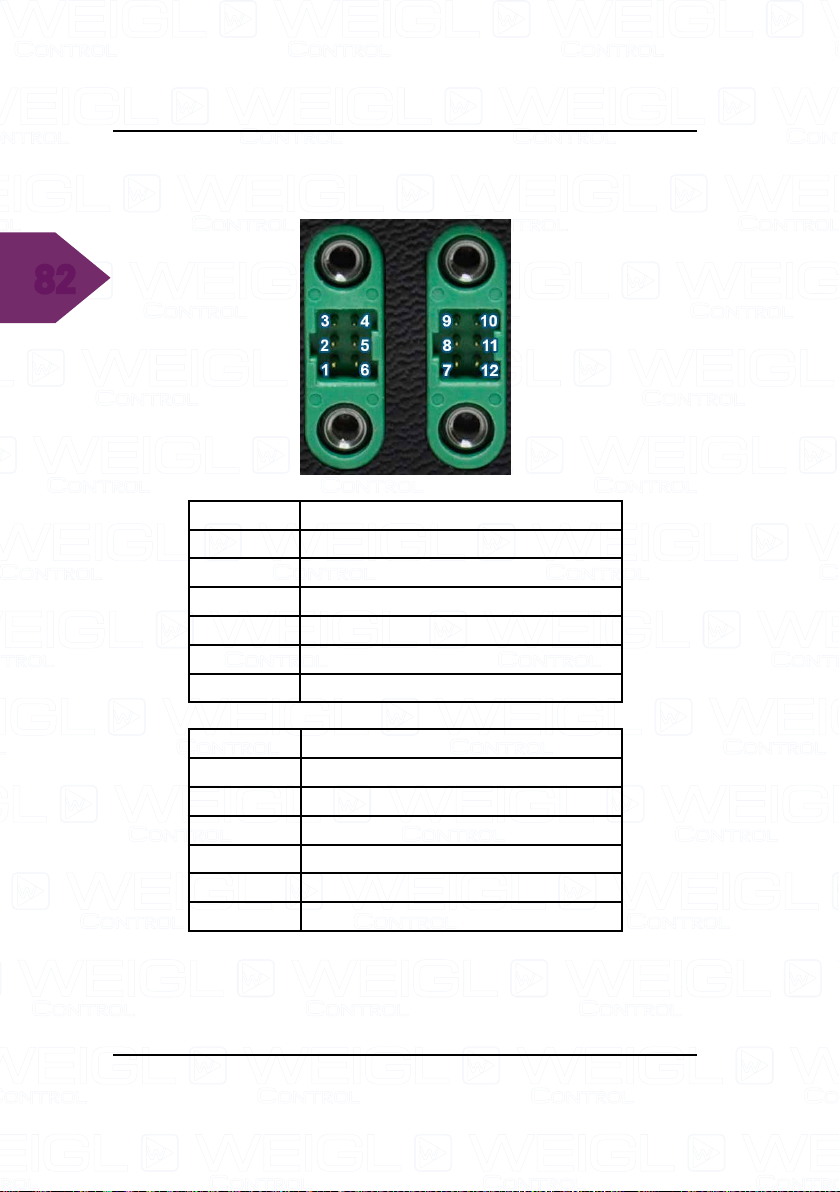
12.6 Pin assignment ProCommander® AX GECKO -
GECKO connector
Connector GECKO left (facing from the rear)
Pin 1 PS-OUT+: 12V-24V/max. 96 Watt
Pin 2 GND
Pin 3 RS485 -
Pin 4 RS485 +
Pin 5 GND
Pin 6 PS-OUT+: 12V-24V/max. 96 Watt
Connector GECKO right (facing from the rear)
Pin 7 PS-OUT+: 12V-24V/max. 96 Watt
Pin 8 GND
Pin 9 CAN-LOW
Pin 10 CAN-HIGH
Pin 11 GND
Pin 12 PS-OUT+: 12V-24V/max. 96Watt
Page 83
ProCommander® AX Appendix
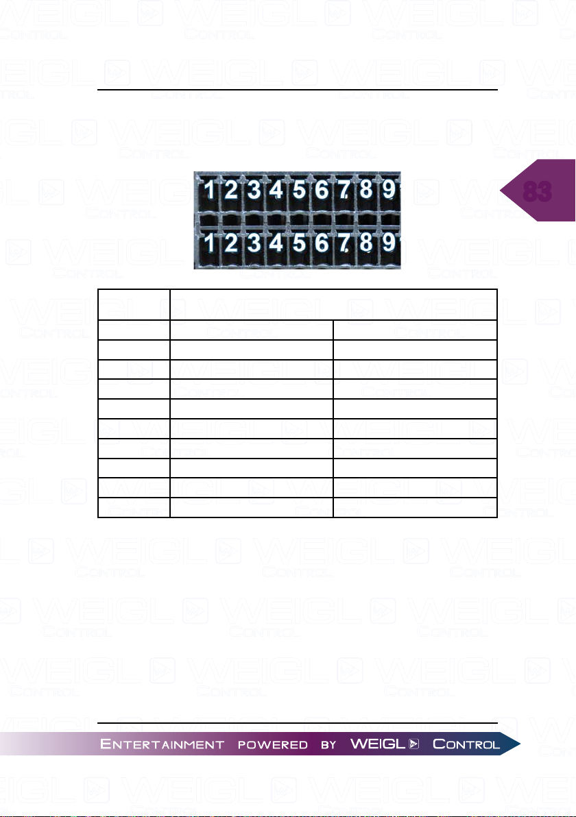
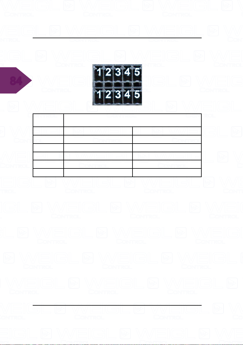
12.7 Assignment ProCommander® AX - Analog IN
1-4/ Digital IN 1-8, Analog OUT 1-4 / Digital
OUT/ PWM 1-4 (Pin 5-8)
83
Analog OUT 1-4/ Digital OUT/ PWM 1-4 (Pin 5-8)
Connector Upper row Lower row
1 Analog Input 1/ Digital Input 1 0-10V Analog Out 1
2 Analog Input 2/ Digital Input 2 0-10V Analog Out 2
3 Analog Input 3/ Digital Input 3 0-10V Analog Out 3
4 Analog Input 4/ Digital Input 4 0-10V Analog Out 4
5 Digital Input 5 Open-Collector/ PWM 1
6 Digital Input 6 Open-Collector/ PWM 2
7 Digital Input 7 Open-Collector/ PWM 3
8 Digital Input 8 Open-Collector/ PWM 4
9 Power-Supply + GND
Analog IN 1-4/ Digital IN 1-8
Maximum current of each analog output: 10mA.
Maximum current of each digital open collector output:
500mA.
Page 84
84
ProCommander® AX Appendix
12.8 Assignment ProCommander® AX GECKO -
Digital IN 5-8 (Pin 1-4), Digital OUT/ PWM 1-4
Digital IN 1-4
Digital OUT/ PWM 1-4
Connector Upper row Lower row
1 Digital Input 5 Open-Collector/ PWM 1
2 Digital Input 6 Open-Collector/ PWM 2
3 Digital Input 7 Open-Collector/ PWM 3
4 Digital Input 8 Open-Collector/ PWM 4
5 Power-Supply + GND
Maximum current of each digital open collector output:
500mA.
Page 85
ProCommander® AX Appendix
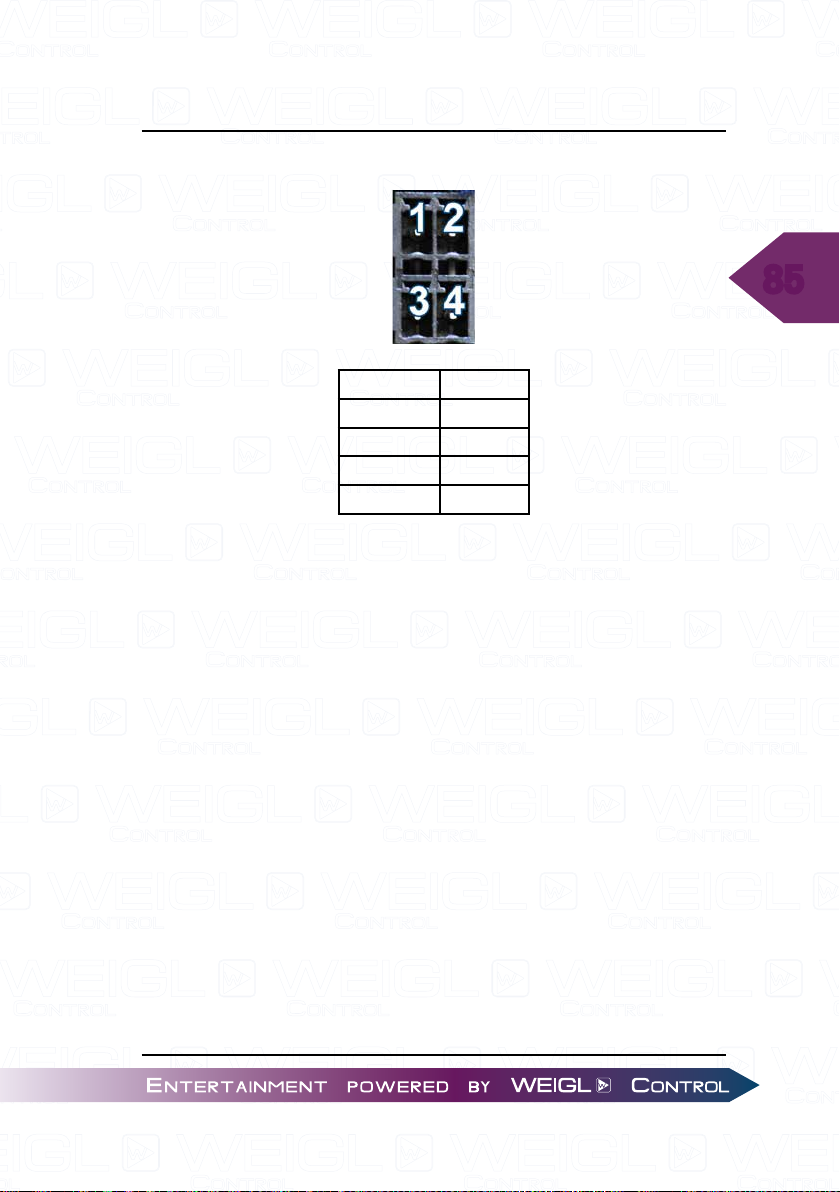
12.9 Pin assignment LS (Loudspeaker)
Connector Function
Pin 1 Left +
Pin 2 Left -
Pin 3 Right +
Pin 4 Right -
85
Page 86

86
ProCommander® AX Appendix
Page 87
Glossary
13 Glossary
Sub-Device-ID
Device address. Each device has its own device address it is
required to issue commands, which are sent to a device to be
correctly handled.
This device can be controlled by all ProCommander
the Sub-ID network communication.
ProCommander
The device can not be controlled by other devices through
the Sub-Device-ID. In the display the information can be found
in the upper right corner as "A:0".
®
mode
®
through
87
Page 88
88
Glossary
Page 89
ProCommander® AX F.A.Q.
14 F.A.Q.
Why should I run a Firmware Update on my Weigl device?
Please do so, if you want that your Weigl device is capable
of all the latest features and able to interpret the new ASCII
commands correctly, which have been developed lately.
Is there any reason why the control.ini will not be executed,
although the commands are correct?
After each "#"-character a new command line have to be
begun. For further information please read the example in the
"Control.ini" chapter. Or check out our latest examples at www.
Weigl.support.
Please run also a Firmware Update on your Weigl device
to ensure that your device is able to interpret the latest ASCII
commands.
Even though I've read the manual, I still have questions
what can I do next?
89
Please check out our Weigl Support and Solutions Center.
There you can submit a ticket or browse through our latest
solutions.
Where do I find the latest Firmware Updates, technical
documentations, video trainings and other F.A.Q.?
Please check out our Weigl Support and Solutions Center.
Is there any easy way to be informed automatically if a new
Firmware Update is available?
You can subscribe our Twitter account WeiglControl.
Page 90
90
ProCommander® AX F.A.Q.
Page 91
Index
15 Index
A
ANALOG 1-4 (0-10V Output) ... 21
Analog IN 1-4 ............................ 83
ANALOG IN 1-4 ........................ 21
Analog MIN- and MAX-value ... 49
Analog OUT 1-4........................ 83
Appendix .................................. 77
Audio ............ See Menu
B
Bass ............. See Audio
C
CE DECLARATION OF CONFOR-
MITY .......................................... 13
Control.ini.................................. 53
Case studies .......................... 58
Project 1 ............................. 58
Project 2 ............................. 59
Project 4 ............................. 61
Project 6 ............................. 63
Project 8 ............................. 65
Example ............... 54, 55, 56
Structure of the Control.ini
file .......................................... 54
Input events ....................... 54
Time events ....................... 54
Variable events .................. 55
91
D
Page 92
Index
92
Day.......... See RealTimeClk
Day-Of-Week .. See RealTimeClk
Digital IN 1-4 ............................. 84
DIGITAL IN 1-4 ......................... 24
Digital IN 1-8 ............................. 83
DIGITAL IN 1-8 ......................... 21
Digital OUT ............................... 83
DIGITAL OUT 1-4 ..................... 24
DIGITAL OUT 5-8 ..................... 21
Digital OUT/ PWM 1-4 ............. 84
Display ...................................... 19
E
EaseIn Time .... See Configure
Electrical and operating require-
F.A.Q. ........................................ 89
FCC and CE Compliance .......... 10
FCC DECLARATION OF CON-
FORMITY................................... 12
FCC Instruction to User ........... 10
Firmware update ...........
See Configuration
Firmware Update ............ 29, 35
Firmware update via batch-
......... See Configuration
file
Firmware Ver. ....... See Info
Folder structure of the Flash
Card .................................. 67
G
GECKO connector .................... 82
, 69
ments ........................................ 79
F
Glossary .................................... 87
H
Hour ......... See RealTimeClk
I
Page 93
Index
IgnStartClr ..... See Configure
Important Information and Safety
Tips ............................................. 7
Info
.............. See Menu
IP-Address ......... See Info
IP Address Configuration ......... 45
IX Connector............................. 81
L
LINE OUT ......................... 22, 25
LS (Loudspeaker) ..................... 85
LS-OUT ............................ 22, 25
LTC-TimeOut ... See Configure
M
MAC-Address ....... See Info
Measurements .......................... 78
Measurements ALU Housing .. 77
microSD .................................... 18
Minute ....... See RealTimeClk
Month ........ See RealTimeClk
N
NETWORK ................................ 17
Network Configuration ............. 45
Network connection between
ProCommander 2 and Pro I/O . 71
P
93
Page 94
Index
94
Port .............. See Info
POWER ............................ 20, 23
ProCommander AX GECKO .... 82
ProCommander AX Update .... 29
ProCommander AX Wi-Fi Config-
uration .............................. 43, 45
Programming the ProCommand-
er 2 ............................................ 69
PWM 1-4 ................................... 84
PWM 5-8 .......................... 21
, 83
R
RealTimeClk ....... See Menu
REAR ...... See Pin assignment
Relay mounted ..... See REAR
RS485-2 Drv .... See Configure
RS485/ CAN ............................. 81
SerialNumber ....... See Info
Set Factory ..... See MainSetup
Set IP-Adrs ..... See MainSetup
Set Port ....... See MainSetup
Setup Wi-Fi Configuration ....... 43
StrtPlaylst ...... See Configure
Structure of the Control.ini file
Input event ............................ 54
Sub-Device-ID ........................... 87
T
Treble ............ See Audio
Tunnel Configuration................ 46
U
USB ........................................... 18
S
V
Variable ..................................... 51
Volume
........... See Audio
W
Page 95
Warranty ................................... 15
Wi-Fi Configuration .................. 43
Wi-Fi Module Firmware Up-
date ........................................... 35
WLAN IP Address Configura-
tion ............................................ 45
WLAN Profile Configuration .... 47
Y
Year ......... See RealTimeClk
Index
95
 Loading...