

Page 1

MicroWeigh Datascale
WeighTech, Inc. Staff
Waldron, Arkansas
1-800-457-3720
March 30, 2011
Page 2

Contents
1 Introduction 4
1.1 MicroWeigh Features . . . . . . . . . . . . . . . . . . . . . . . . . . 4
1.2 MicroWeigh Applications . . . . . . . . . . . . . . . . . . . . . . . . 4
2 Keypad Operation 4
3 Main menu items 5
3.1 “Power off” . . . . . . . . . . . . . . . . . . . . . . . . . . . . . . . 5
3.2 “Washdown” . . . . . . . . . . . . . . . . . . . . . . . . . . . . . . 5
3.3 “Totals” . . . . . . . . . . . . . . . . . . . . . . . . . . . . . . . . . 5
3.4 “Calibrate” . . . . . . . . . . . . . . . . . . . . . . . . . . . . . . . 5
3.5 “Setup Menu” . . . . . . . . . . . . . . . . . . . . . . . . . . . . . . 5
3.6 “Audit cfg” . . . . . . . . . . . . . . . . . . . . . . . . . . . . . . . 5
3.7 “Audit cal” . . . . . . . . . . . . . . . . . . . . . . . . . . . . . . . 5
3.8 “Tare” . . . . . . . . . . . . . . . . . . . . . . . . . . . . . . . . . . 6
4 How to Step Through Menus 6
4.1 Menus can contain several different items . . . . . . . . . . . . . . . 6
4.2 How to enter a number . . . . . . . . . . . . . . . . . . . . . . . . . 6
4.3 How to select from a list . . . . . . . . . . . . . . . . . . . . . . . . . 7
5 General Scale Operations 7
5.1 Scale On Procedure . . . . . . . . . . . . . . . . . . . . . . . . . . . . 7
5.2 Scale Off Procedure . . . . . . . . . . . . . . . . . . . . . . . . . . . 8
5.3 Zero Procedure . . . . . . . . . . . . . . . . . . . . . . . . . . . . . 8
5.4 Units Procedure . . . . . . . . . . . . . . . . . . . . . . . . . . . . . 8
5.5 Tare Operation . . . . . . . . . . . . . . . . . . . . . . . . . . . . . 8
5.6 Data Mode . . . . . . . . . . . . . . . . . . . . . . . . . . . . . . . 8
6 Label Setup 9
7 Calibration Procedure 10
7.1 Entering the calibration menu . . . . . . . . . . . . . . . . . . . . . . 10
7.2 Keying in cal weight . . . . . . . . . . . . . . . . . . . . . . . . . . 10
7.3 Calibration Example . . . . . . . . . . . . . . . . . . . . . . . . . . 10
7.4 Establishing a zero . . . . . . . . . . . . . . . . . . . . . . . . . . . 12
7.5 Accepting a cal weight . . . . . . . . . . . . . . . . . . . . . . . . . 12
8 Scale Parameters 13
8.1 “Units” . . . . . . . . . . . . . . . . . . . . . . . . . . . . . . . . . 13
8.2 “Capacity” . . . . . . . . . . . . . . . . . . . . . . . . . . . . . . . . 13
8.3 “Resltn” . . . . . . . . . . . . . . . . . . . . . . . . . . . . . . . . . 13
8.4 “Stability” . . . . . . . . . . . . . . . . . . . . . . . . . . . . . . . . 13
8.5 “Motion sns” . . . . . . . . . . . . . . . . . . . . . . . . . . . . . . 13
8.6 “Prefilter” . . . . . . . . . . . . . . . . . . . . . . . . . . . . . . . . 13
2
Page 3

8.7 “AZT” . . . . . . . . . . . . . . . . . . . . . . . . . . . . . . . . . . 14
8.8 “AZT band” . . . . . . . . . . . . . . . . . . . . . . . . . . . . . . . 14
8.9 “Calibrate” . . . . . . . . . . . . . . . . . . . . . . . . . . . . . . . 14
8.10 “IZ set” . . . . . . . . . . . . . . . . . . . . . . . . . . . . . . . . . 14
8.11 “lb units” . . . . . . . . . . . . . . . . . . . . . . . . . . . . . . . . 14
8.12 “kg units” . . . . . . . . . . . . . . . . . . . . . . . . . . . . . . . . 14
8.13 “g units” . . . . . . . . . . . . . . . . . . . . . . . . . . . . . . . . . 14
8.14 “oz units” . . . . . . . . . . . . . . . . . . . . . . . . . . . . . . . . 14
8.15 “Defaults” . . . . . . . . . . . . . . . . . . . . . . . . . . . . . . . . 14
9 Menus 15
9.1 Main Level . . . . . . . . . . . . . . . . . . . . . . . . . . . . . . . 15
9.2 Setup menu . . . . . . . . . . . . . . . . . . . . . . . . . . . . . . . 15
9.3 Parameters . . . . . . . . . . . . . . . . . . . . . . . . . . . . . . . . 16
9.4 Totals menu . . . . . . . . . . . . . . . . . . . . . . . . . . . . . . . 16
9.5 Label setup . . . . . . . . . . . . . . . . . . . . . . . . . . . . . . . . 17
9.6 New/Edit label . . . . . . . . . . . . . . . . . . . . . . . . . . . . . . 17
9.7 Info menu . . . . . . . . . . . . . . . . . . . . . . . . . . . . . . . . 18
10 Troubleshooting 18
10.1 Load cells . . . . . . . . . . . . . . . . . . . . . . . . . . . . . . . . 18
10.2 Before calling WeighTech... . . . . . . . . . . . . . . . . . . . . . . 19
11 Replacement Parts 19
12 Wiring Diagram 20
13 Load Cell Color Codes 21
3
Page 4

1 Introduction
With the WeighTech MicroWeigh a combination of state-of-the-art technology with
common down-to-earth basics creates a digital indicator that makes troubleshooting and
actual maintenance repair so simple that anyone can be trained to make repairs on this
indicator in just minutes.
1.1 MicroWeigh Features
• High impact ABS alloy construction.
• Highly visible, easy-to-read display with adjustable contrast and backlight.
• Environmentally sealed touch-sensitive operator control panel.
• Standard units of measure include grams, kilograms, ounces, and pounds.
•
RS-232 and Infrared communications are standard with RS-485 option available.
• Wireless data collection using a PDA with WeighTech ScaleTrax software.
1.2 MicroWeigh Applications
• Standard weighing
• Label printing
• Tank or vat weighing
• Checkweighing (boxes, bags, and pieces)
• Bench and floor scales
• Batch weighing
2 Keypad Operation
The WeighTech MicroWeigh keypad is a watertight sealed touch sensitive sensor. The
keys are actually sensitive to contact area, not force. Press lightly with the ball of your
fingertip as though you were giving fingerprints. Best results come from using the
ball of your finger, not the very tip. Most objects will not trigger the keypad–knives,
screwdrivers, tools, etc. do not have enough surface area in contact with the key to
register as a keypress. (You might get it to trigger with a medium sized conductive bolt
head, if you have skin in contact with the bolt.)
One consequence of the design of the touch sensitive keypad is that it is sensitive
to water streams. For this reason, WeighTech includes a unique “washdown mode” to
prevent unwanted keypad activity during washdown/sanitation/cleanup intervals. When
the indicator is in washdown mode, the indicator will weigh normally but the keypad is
locked out.
4
Page 5

To unlock the keypad, you must play follow the leader. One key will be lit. Press
it. Another key will then light up. Press it. Continue until the indicator displays “Exit
washdown”. The indicator will require that you press five keys in a row correctly before
it will unlock the keypad. Any wrong keypress will restart the counter back to five. The
odds are extremely slight that random water splashing would ever be able to trigger the
correct keys in the correct order to unlock the keypad.
3 Main menu items
3.1 “Power off”
Touch the enter key to select this menu item, which will power down the indicator. If
the auto-on jumper is installed on the interface board, the indicator will immediately
turn back on.
3.2 “Washdown”
This function puts the indicator in washdown mode to prevent inadvertent keypad
activity. See the washdown section of this manual for more information.
3.3 “Totals”
This function leads to the totals submenu.
3.4 “Calibrate”
This function allows you to calibrate the scale. Refer to the calibration section of this
manual for details.
3.5 “Setup Menu”
Enter the setup submenu, where scale parameters can be viewed or set.
3.6 “Audit cfg”
Displays the audit counter for configuration. Every time a sealed scale parameter is
modified this counter will increment by one. This setting is nonvolatile (it will be
retained even if the batteries go dead) and cannot be altered except by modifying an
audited configuration parameter.
3.7 “Audit cal”
Displays the audit counter for calibration. Every time the scale is calibrated this counter
will increment by one. This setting is nonvolatile (it will be retained even if the batteries
go dead) and cannot be altered except by performing a calibration.
5
Page 6

3.8 “Tare”
Keypad entered tare: Touch the Enter key to set a new pushbutton tare by scrolling
through digits one place at a time. Keypad tare values are entered in the current units,
and are limited to be greater than gross zero weight and less than the indicator capacity.
Entering a tare of zero will clear any existing tare from indicator.
4 How to Step Through Menus
From the main weight display, press the “Menu/Help” key. You are now in a menu, and
the keys now have different functions:
Cancel Help Enter Down Up
• “Cancel” will back you out of the menu one level at a time.
• “Help” will display information about the current choice (option).
• “Enter” has various functions, depending on where you are in the menu.
• The “Down” key will scroll backward through the menu choices.
• The “Up” key will scroll forward through the menu choices.
4.1 Menus can contain several different items
An item with a “*” on the right end will do something when you press the enter key–
something might be turn the indicator off, drill down into another menu, clear totals, or
start a calibration routine. The item with a numeric value (scale capacity, for instance)
at the right side of the display might allow you to change the number by pressing the
enter key. An item with text (such as “on” or “off”) at the right side of the display might
allow you to select from a list of options by pressing the enter key. Some items are just
for reference and cannot be changed at all. Examples of reference items would be the
software name and revision–these are set when the software is written and cannot be
changed.
4.2 How to enter a number
Using the calibration routine as an example: Press the “Enter” key. The indicator display
will show “Cal weight ” and the cursor will be blinking. The blinking cursor is the
clue that you can enter an arbitrary number using the up, down, right, and enter keys.
Pressing the up/down keys will scroll through the list (0 1 2 3 4 5 6 7 8 9 - . ) in
turn. When the desired number appears, press the right arrow (menu/help) key. The
blinking cursor will advance one digit to the right, leaving your selected number in
place. Continue this sequence until the desired numeric value is visible on the display.
Press the “Enter” key to accept the value, or the “Cancel” key to abort.
Example: Enter a calibration weight of 25 pounds
• Start with the indicator at a normal weight display (“ 0.00 lb”)
6
Page 7

• Press the “Menu/Help” key
•
Scroll through the main menu using the up or down arrow keys until “Calibrate *”
is displayed on the indicator
• Press the “Enter” key to start the calibration routine
•
The indicator may display “Password” if a calibration password is required. If so,
enter it (default calibration password is “Zero” “Zero” “Zero”)
• The indicator should now be displaying “Cal Weight” and a blinking cursor.
• Press the up arrow key. The display should now show “Cal weight 1”
• Press the up arrow key again. The display should now show “Cal Weight 2”
•
Press the right arrow key to accept the first digit (2) and advance the blinking
cursor to the next digit. The indicator should display “Cal weight 2 ”
•
Press the up arrow key five times to select a 5 as the second digit. The indicator
should now display “Cal weight 25”
• Press the “Enter” key to accept 25 pounds as a calibration weight.
•
The indicator will display “Cal–zero weight”. Press the “Cancel” key to abort the
calibration process.
4.3 How to select from a list
This is very much like stepping through a menu. Some settings (such as displayed
resolution) must be limited to one of several predetermined values. To edit one of these
settings, press the “Enter” key. The currently selected value will move from the far right
of the display to the left. This indicates that you may use the up and down arrow keys to
scroll through a list of possible values for this setting. Once you’ve selected a value for
the setting, press the “Enter” key to complete the selection process. As always, pressing
the “Cancel” key will cancel the selection and restore the setting to the previous value.
5 General Scale Operations
5.1 Scale On Procedure
Touch the “Zero / On” key. Indicator will come on and display will read “MicroWeigh
by WeighTech” and then continue to the weigh mode. At this point the scale is ready
for product or operator input.
7
Page 8

5.2 Scale Off Procedure
To turn the scale off touch the “Menu / Help” key. The indicator will display “Power
off *”. At this point touch the “Print / Enter” key and scale display will go blank, and
the indicator will be off. (If the auto-on jumper is installed on the interface board, the
indicator will immediately power up.)
5.3 Zero Procedure
To zero the indicator touch the “Zero / On” key and the indicator will take a new zero.
If the current weight reading is unstable, under capacity, or over capacity, no new
pushbutton zero will be established.
5.4 Units Procedure
To change the units of measure touch the “Units / Cancel” key. The units will change
between pounds, kilograms, grams and ounces (assuming all the units are enabled in the
“Parameter” menu) each time that the key is touched.
5.5 Tare Operation
Press and hold the tare button to establish a pushbutton tare reference. If a valid tare is
established, the indicator will switch to the net weight display. If the gross weight is
equal to or less than gross zero, any existing tare value will be cleared, the display will
show “Tare cleared” for about one second, and the display will revert to gross weight
display.
Toggle between net and gross display modes by touching the “Tare” button. If no
tare reference has been established, the indicator will not switch to net weight mode.
An arbitrary tare weight can be entered from the tare setting in the main menu
(keypad tare). Scroll and select digits one at a time to enter the desired value. The
indicator will not accept a keypad tare value in excess of scale capacity, or less than
zero. Entering a value of zero will clear any existing tare and return the indicator to the
gross weight display mode. Units for the entered weight is the same as the currently
displayed units. (To enter a six pound tare, be sure that the display is showing weight in
pounds before entering the keypad tare.)
5.6 Data Mode
Press the “Menu” key, then scroll until “Data mode” is visible. Press “Enter”. The
indicator will then prompt for the kill date, which should be entered in mm.dd.yy format
(such as “5.2.02” for May 2nd, 2002). As a shortcut, you can just press the “Enter”
key to use the current day as the kill date. Once the kill date has been entered, the
indicator will display “Data mode on” for a couple of seconds and enter datascale mode.
In datascale mode, the display will show the current product code on the left side, and
the current net weight on the right side. Several of the keys will also act differently in
datascale mode. Touch the “Print” key while the current weight is stable to print a label.
8
Page 9
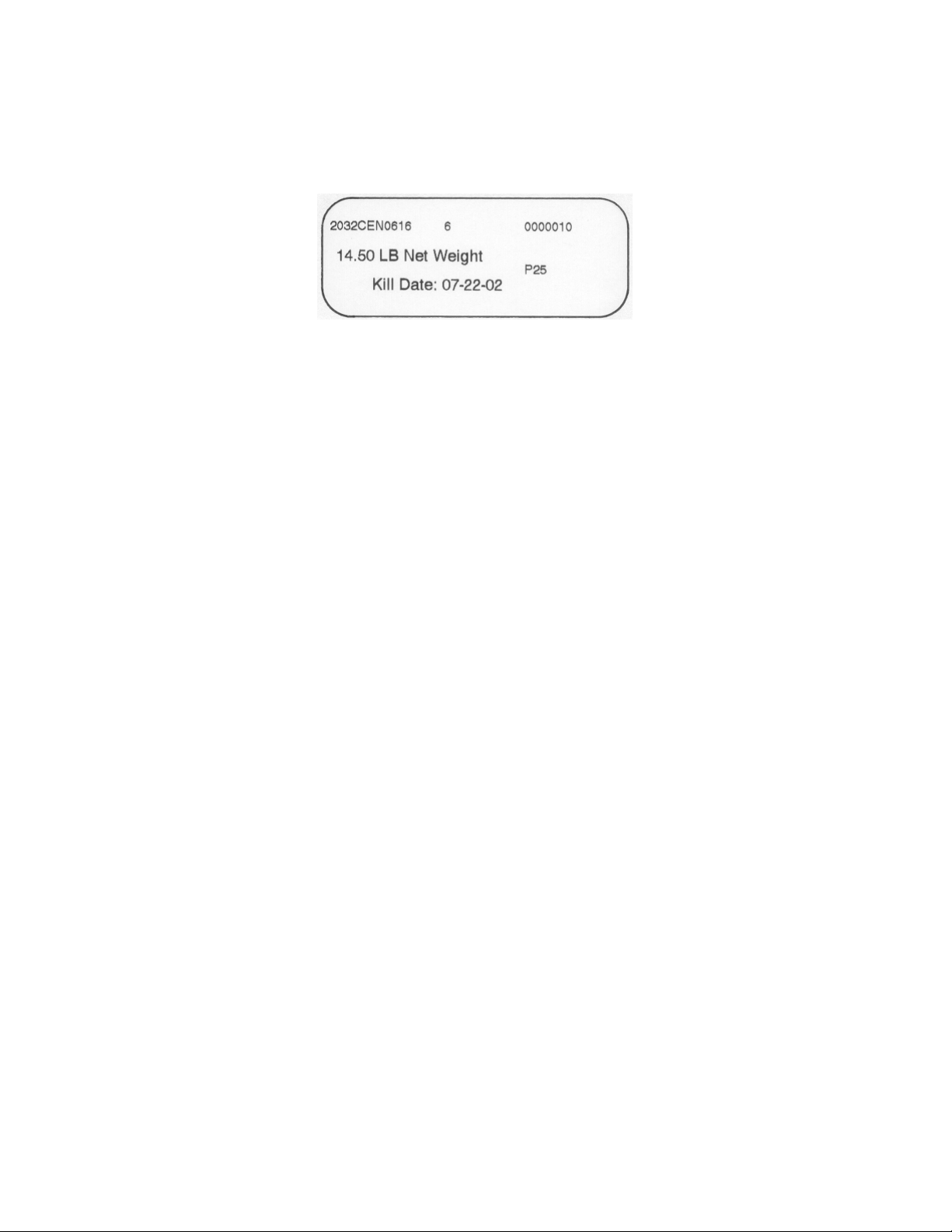
Figure 1: A sample text-only label
The “Units/Cancel” key will undo the last printed label. The “Menu” key will display a
list of product codes and the “Product Exit” option. To switch to another product code,
simply scroll using the up and down arrows until the desired product code is displayed
and press the “Enter” key. Selecting “Product Exit” will exit the datascale mode and
return the scale to normal weighing operation.
Entering the use-by date is optional. If you do not enter a date and instead just touch
the “Enter” key, the indicator will calculate the use-by date from the kill date and the
use-by interval in the label setup section.
6 Label Setup
First, decide whether a full barcode label or a simpler text label is required. The text
label requires less information to be entered–only a product code and tare weight for
most applications. Create a new label by pressing the “Menu” key, scrolling to “Label
Setup”, and entering the label setup password (“Units” “Units” “Units”). The indicator
will then allow you to enter the product code, UPC (only used with barcode label), a tare
weight, an optional serial number (only used if serializing by product code), an auxiliary
field (used in place of the serial number if serialization is disabled), and a pallet size
(used only with barcode label).
Once the label information has been entered, the indicator will ask you to confirm
before actually storing the new label and product code to memory (“New code...sure?”).
Press “Enter” to confirm, or “Cancel” to abort. Once created, the label information is
stored in nonvolatile memory and will not be lost when the indicator is powered off.
For example, this text-only label contains:
“2032CEN0616”: “203” is the Julian day, “2” is the units digit of the current year (2002),
“CEN” is the plant name (Center, TX), “06” is the line number (assigned in the label
setup menu), and “16” is the current hour, in 24 hour format.
“6” is the line number.
“0000010” is the serial number.
“14.50 LB Net Weight” is the current weight, using the tare weight (in pounds) for
this product code.
“P25” is the product code (the “P” is automatic).
“Kill Date: 07-22-02” is the entered kill date.
9
Page 10
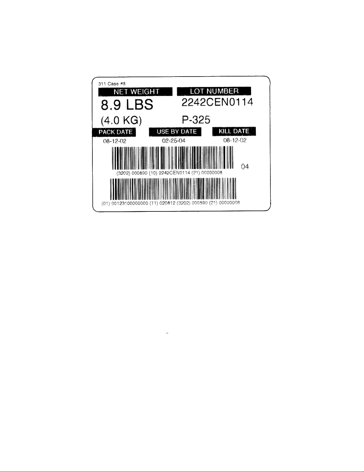
Figure 2: A sample full label
7 Calibration Procedure
7.1 Entering the calibration menu
With the indicator on and displaying weight, touch the “Menu / Help” key. The display
will read “Power off *”. Use the up / down arrows until the display reads “Calibrate
*”. Touch the “Print / Enter” key and the display should then show “Password”. At
this point key in the calibration password. (The default calibration password is “Zero”
“Zero” “Zero” .)
7.2 Keying in cal weight
The display will show “Cal weight ” and the cursor will be blinking. Using the up,
down, and right keys to enter the size of your calibration weight in pounds (i.e. 1, 2, 5,
or 10). Press “Enter” to accept the cal weight, or “Cancel” if you make a mistake.
7.3 Calibration Example
(Entering a 25.00 lb cal weight value.) The blinking cursor is the clue that you can enter
an arbitrary number using the up and down keys. Pressing the up/down keys will scroll
through the list (0 1 2 3 4 5 6 7 8 9 - . ) in turn. When the desired number appears (2),
press the right arrow “Menu / Help” key. The blinking cursor will advance one digit to
10
Page 11
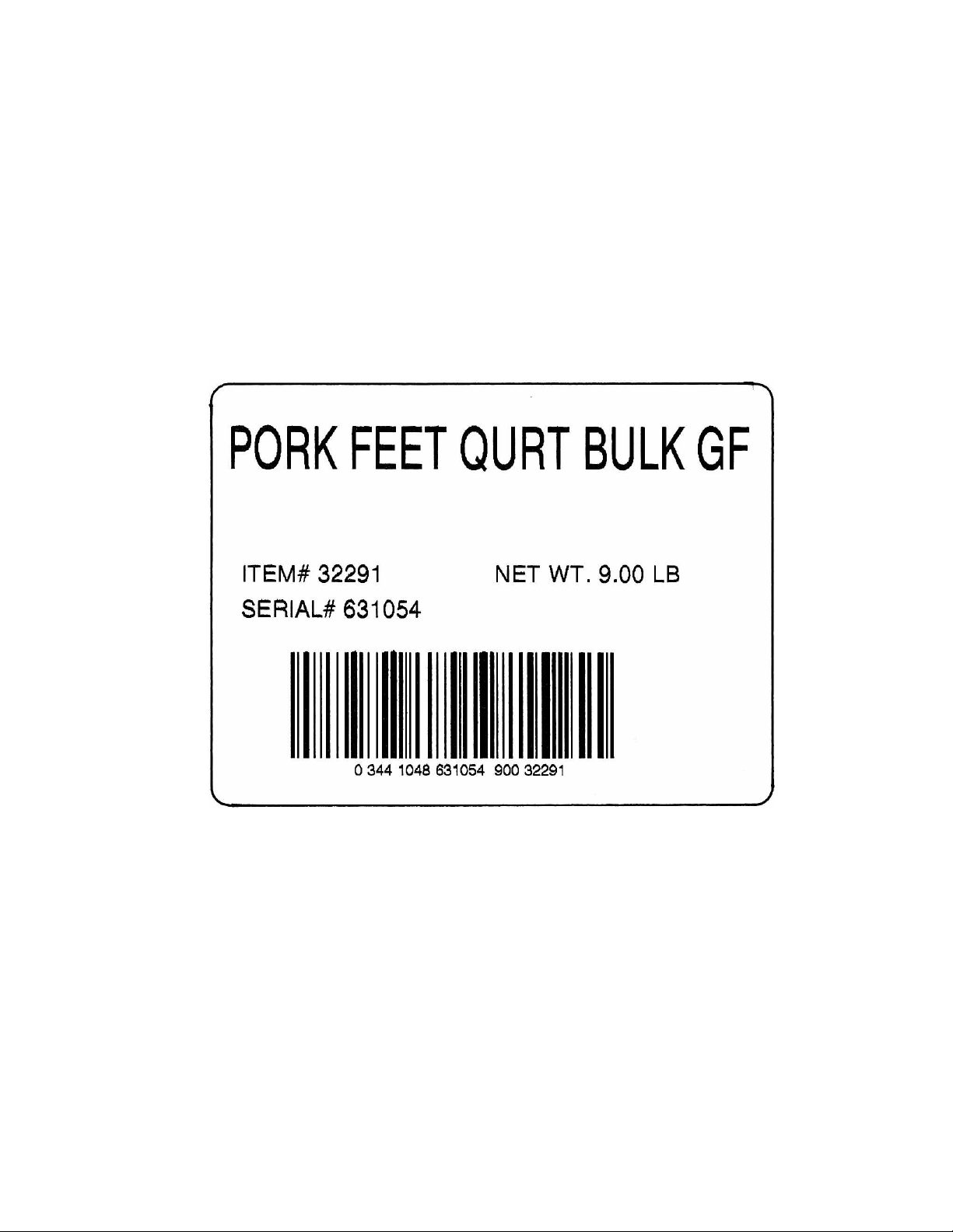
Figure 3: Neosho label sample
11
Page 12
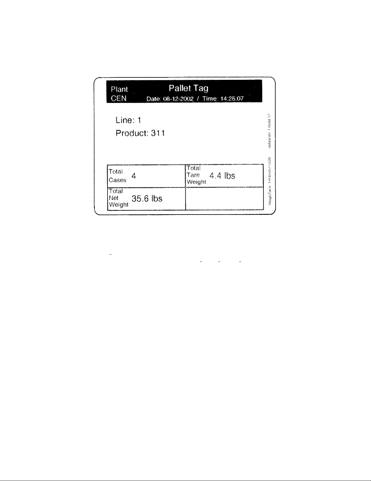
Figure 4: A sample pallet tag
the right (2 ), leaving your selected number in place. Continue this sequence until the
desired numeric value is visible on the display (25 ) (25. ) (25.0 ) (25.00). Press the
“Enter” key to accept the value, or the “Cancel” key to abort.
7.4 Establishing a zero
The indicator will display “Cal–zero weight”. Clear the weighing platform of any
foreign objects and once all vibration has died out, press the “Enter” key. Make sure
that the platform is not disturbed during this process. Indicator will display “Zeroing...”
as it takes an average reading of the zero offset weight (about three seconds).
7.5 Accepting a cal weight
The indicator will then display “Cal–add weight”. Add weight to the weighing platform
(the weight should be the same amount as the keyed in cal weight) then touch the “Enter”
key. The indicator will display “Scaling...” for about three seconds as it performs
internal calculations. Finally, the indicator will display “Cal done” for about one second
once the calibration cycle is complete.
12
Page 13

8 Scale Parameters
To get to the parameters touch the “Menu/Help” key (indicator will display “Power off
*”). Use the up or down arrows until the indicator displays “Setup Menu”. Touch the
“Print/Enter” key and the indicator will prompt for a password. The password for this
step will be as follows: starting from the left side of the keypad touch each key in turn
from left to right. After entering the password the indicator will display “Parameters *”.
At this point touch the “Print/Enter” key to access the parameters. Use the up and down
arrows to scroll through and view each parameter.
8.1 “Units”
This parameter controls the setup unit of the indicator. Select from pounds (lb), kilograms (kg), grams (g), and ounces (oz). Once set, the indicator capacity, resolution, and
calibration weights will be entered in this unit. The units parameter is both sealed and
audited.
8.2 “Capacity”
Capacity sets the maximum capacity of the indicator, in setup units. This parameter
is both sealed and audited. Factory default is 0, which must be changed before the
indicator will weigh.
8.3 “Resltn”
Parameter that sets the resolution of the indicator. Resolution is limited to values
available on the scroll list. Resolution is set in terms of the setup units. This parameter
is both sealed and audited.
8.4 “Stability”
This parameter controls how many consecutive weight readings are required to be within
the motion sense band before the weight indication is considered to be stable. The
indicator reads the analog input 7.5 Hz (7.5 times per second), so the default setting
of four requires about a half second of stable weight. Either the net or gross light will
come on when the weight is stable. This parameter is both sealed and audited.
8.5 “Motion sns”
Amount of motion, in divisions, allowed before the weight is considered unstable.
Default is one division. This parameter is both sealed and audited.
8.6 “Prefilter”
Length of the Prefilter buffer. Larger numbers provide slower and cleaner weight
readings. Default is 2. This parameter is both sealed and audited. Range?
13
Page 14

8.7 “AZT”
Auto zero tracking on/off. This parameter is neither sealed nor audited. When on, stable
weights within the “AZT band” of zero will automatically rezero the scale.
8.8 “AZT band”
Amount of weight, in divisions, that can be automatically zeroed out at one time. Default
is 1 division. Parameter is sealed and audited.
8.9 “Calibrate”
This function starts the indicator calibration routine. It is sealed and audited. Refer to
the calibration section of this manual for details.
8.10 “IZ set”
When this parameter is on, the indicator will attempt to establish a new initial zero
every time the indicator powers on. HB44 limits the amount of weight that can be
initially zeroed to 20% of scale capacity. (This initial zero does not reduce the indicator
capacity.) This parameter is both sealed and audited.
8.11 “lb units”
Select on/off to enable or disable the pounds (lb) units when the Unit key is pressed in
weighing mode. This parameter is both sealed and audited.
8.12 “kg units”
Select on/off to enable or disable the kilograms (kg) units when the Unit key is pressed
in weighing mode. This parameter is both sealed and audited.
8.13 “g units”
Select on/off to enable or disable the grams (g) units when the Unit key is pressed in
weighing mode. This parameter is both sealed and audited.
8.14 “oz units”
Select on/off to enable or disable the ounces (oz) units when the Unit key is pressed in
weighing mode. This parameter is both sealed and audited.
8.15 “Defaults”
Restore all configuration parameters to factory default. This function is sealed and
audited. Restoring factory defaults will require that the indicator be calibrated and
reconfigured before it will weigh.
14
Page 15

9 Menus
9.1 Main Level
Power off Turn off the indicator
Data mode Go into datascale mode
Washdown Disable keypad to prevent false keypresses during washdown
Totals Display total weight, batch count, and average batch weight
Calibrate Enter quick calibration routine
Label setup Enter the label setup menu
Setup menu Bunch of stuff...see below
Audit cfg
Audit cal Number of times indicator has been calibrated (HB44)
Tare Current tare weight
9.2 Setup menu
Parameters Scale settings
Speed keys Speed key setup
Weighment Weighment target and database control
Hotkey test Hotkey communications test
Info menu Troubleshooting features
Clock Set time/date
Contrast Control display intensity
Number of times an audited config parameter has been changed
(HB44)
15
Page 16

9.3 Parameters
Setup units
Capacity Scale capacity, in setup units
Resltn Scale resolution, in setup units
Stability Number of consecutive readings required for stability
Motion sns
Prefilter Super filter adjustment–bigger numbers make the filter slower
AZT
AZT band Amount of weight (in divisions) that can be zero tracked out
Calibrate Start calibration routine
IZ set Set initial zero at power up (default to off)
Address Communications address
lb units On/Off: Enables the units toggle key to include pound units
kg units On/Off: Enables the units toggle key to include kilogram units
g units On/Off: Enables the units toggle key to include gram units
oz units On/Off: Enables the units toggle key to include ounce units
Remote 1 Function when remote switch is pressed quickly
Remote 2
Cntst Three key quick contrast adjustment on/off
Defaults
Setup units: used for entering capacity and resolution (defaults to
pounds)
Number of divisions allowed before weight is considered unstable
On/Off: Autozero tracking on/off, only affects weights near zero
Function when remote switch is pressed and held for a couple of
seconds
Restore scale to factory default settings (all settings will be lost!)
9.4 Totals menu
Clear totals
Print totals Print totals for each product code
Print settings Print all scale settings
Print codes Print all active product codes and label settings
Clear totals–you will be asked to confirm by pressing “Enter” a
second time
16
Page 17

9.5 Label setup
New label Create a new product code and label
Edit label Modify an existing product code and label
Delete label Delete a product code and label
P-code Set plant code, which will appear on labels as “P-”
Plant name Set the three letter plant name code
Line Two digit production line identifier
Serial
Ser mode
Label
L margin
B margin
Backfeed Distance past end of label to advance
# labels Number of labels to print when key is pressed
Current serialization number for all products (only used if “Ser
Mode” is set to “Code”
“All”/“Code”/“Aux”: Select how serial numbers increments for
each product code
“Full”/“Text”: Select between full barcode label and smaller text-
only label
Fudge factor to move print area away from left edge of label stock
(default to 0)
Fudge factor to move print area away from bottom edge of label
stock
9.6 New/Edit label
Code
UPC
Tare Tare weight for this product code, in pounds
Serial
Aux
Pallet size Not used
Use-by Number of days from kill date to use-by date
Wgt Total net weight for this product code
Cases Total case count for this product code
Product code, limited to about 16 characters, no duplicates are
allowed
UPC code, must be 14 digits (shorter codes will have leading
zeros added), all numeric
Incrementing serial number for this product code only, only used
if “Ser Mode” is set to “Code”
Non-incrementing field number for this product code, used instead of serial if “Ser Mode” is set to “Aux”
17
Page 18

9.7 Info menu
ADC Raw counts display from analog to digital converter
Offset Calibration zero offset, in raw counts
App Name of firmware app (datascale 1)
Build Software revision info (Build 66)
Date Date firmware was compiled (03/30/2011)
Time Time of firmware compilation (08:28:31)
Batt Current power supply/battery input voltage, in V
S1+
S1—
Excite Load cell excitation voltage (should be about 4.5V)
Deadload
232 audit Transmit audit trail through RS-232 port (experimental)
IZ autoset Force a new initial zero
IZ Current initial zero setting
Debug msg
Off Timer Minutes to automatic shutoff, set to 0 to disable auto-off
Bootload WeighTech use only
Load cell #1 positive signal voltage (should be about half of
excite voltage with good load cell)
Load cell #1 negative signal voltage (should be almost exactly
the same as S1+ voltage)
Display platform deadload weight (assumes load cell has no
offset)
On/Off: Turn this parameter on for more extensive messages
during boot and dump cycle
10 Troubleshooting
10.1 Load cells
Go to the “Info menu” and verify that the “Excite” voltage is about 4.5V. A reading of
less than 1V probably indicates a short from excite to ground. Confirm by removing the
load cell connections. If the excite voltage reads normal with the load cell disconnected,
you’ve got a short in the cable or a bad load cell.
Check to see that the signal voltage in the “Info menu” are about half of excite and
equal. If one signal voltage is near zero, or near 4V, you may have a disconnected signal
wire. Check that connection at the interface board. If the signal voltages are not near
zero or 4V, but are more than a 0.5V different, you may have the load cell miswired, or
a bent load cell.
If the indicator constantly shows “OVERLOAD” or “UNDERLOAD”, follow the
instructions above. In addition, go to the “Info menu” and watch the “ADC” reading
(raw counts). It shouldn’t vary more than 100-300 counts with a good load cell and a
stable environment. With no load on the cell, it should be within +/- 10,000 counts of
zero. (Deadload can cause the no load reading to shift.) If the no load reading is really
large (say, greater than one million counts or less than negative one million counts) and
the connections are solid, you probably have a bent load cell.
Unstable or noisy weights? Perform all the steps listed above. A really good test is
to temporarily disconnect the load cell and substitute a known good load cell simulator
18
Page 19

(available for purchase from WeighTech), or a known good load cell. Calibrate the scale
with a convenient test weight and check to see if the weight reading is stable. If so,
the noisy load cell has probably been damaged or water-soaked. If the indicator still
displays a noisy weight with a load cell simulator, the problem may be in the indicator.
Contact WeighTech for further assistance.
10.2 Before calling WeighTech...
Write down a few key pieces of information. Gather the indicator serial number from
the front panel, the software application name and build number from the “Info menu”,
and grab the current settings if you have access to a Palm. If anything on the indicator
has changed, been replaced, or been modified, mention that to the service technician too.
If the problem involves fill rates, hangs, or questions regarding machine capabilities,
be ready to describe the product, product flow rate, and any bag/box/tote/combo sizes.
If you’re calling about unstable weight readings, over/underload, or other load cell
related problems, have the ADC, excite, and signal readings from the “Info menu”
handy. When calling, be prepared to describe what is wrong (“it doesn’t work!” isn’t a
good description–“hopper gate doesn’t shut in off mode” is much better) and what you
expected to see.
11 Replacement Parts
Part Number Description
1000-10 Load cell, 200 lb capacity
1001-40 Datamax printhead assembly
BB-2020-200 Bench base, 20”x20” w/ 200 lb capacity load cell
EF0009 Strain relief, MicroWeigh
HW0018 MicroWeigh housing screw (pack of 4)
HW0019 Screw, 6-19 x 0.375, trilobe PPH, MicroWeigh (pack of 10)
HW0020 Lobed knobs, MicroWeigh (pack of 2)
WE0028-101 Datamax I class label printer w/ internal rewind
WE0028 Main gasket, MicroWeigh
WE0029-1 Power cord, detachable, MicroWeigh
WE0031 Front housing assembly, MicroWeigh
(specify firmware name and revision)
WE0032 Back housing assembly, MicroWeigh
WE0035-101 Interface board assembly, MicroWeigh
WE0059 Printer cable
19
Page 20
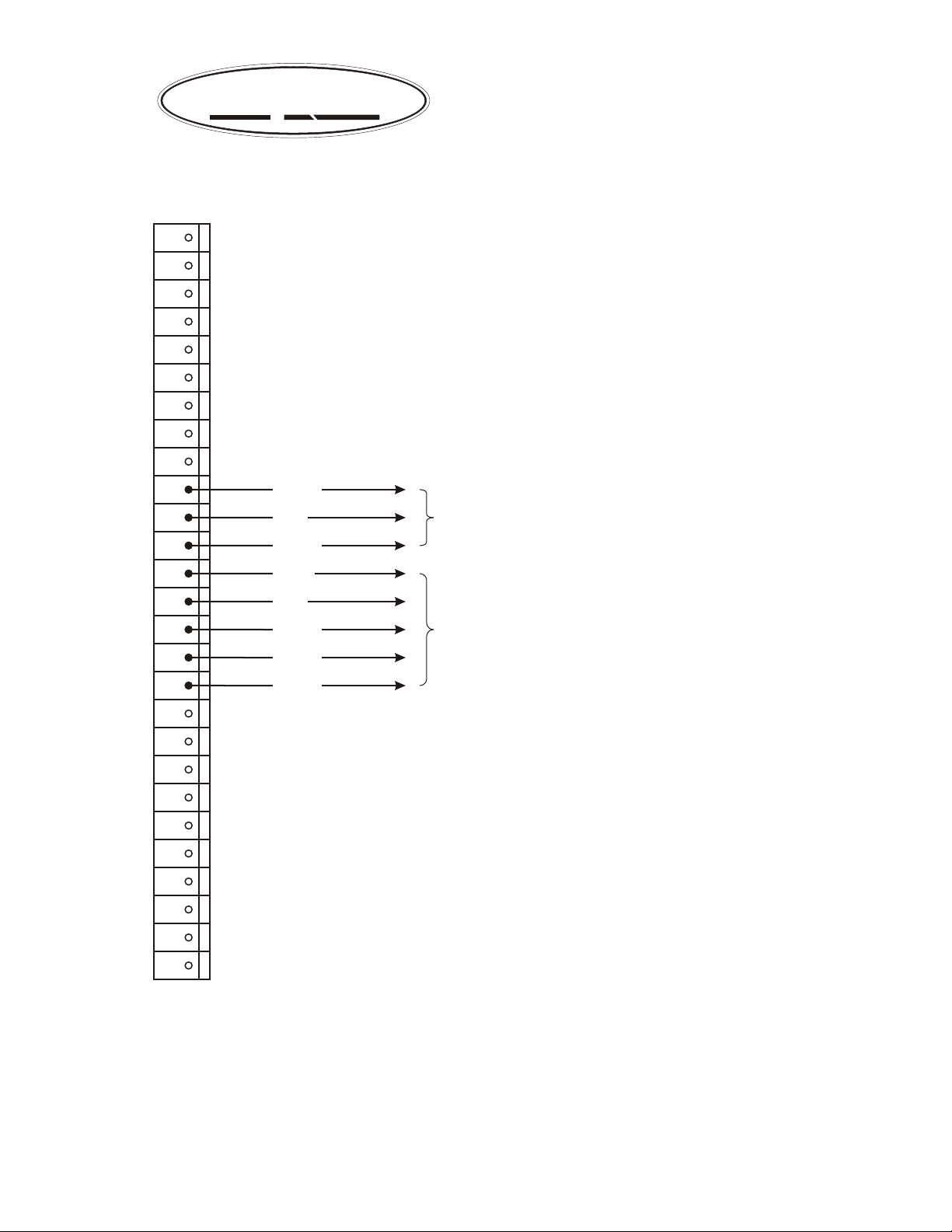
TX+
TX-
RX+
RX-
COM
RI1
RI2
RO1
RO2
Weigh
Te ch
JOB: DATASCALE
PLANT:
TM
LOCATION:
PAGE: 1 OF 1
DRAWN BY: NEWELL
FIRMWARE: DATASCALE_1
DATE: 03-30-2011
RX
GND
S1+
S1-
EX+
EX-
SHD
S2+
S2-
EX+
EX-
S3+
S3-
EX+
EX-
S4+
TX
BLACK
RED
CLEAR
WHITE
RED
GREEN
BLACK
SHIELD
PRINTER
LOAD CELL
S4-
Page 21
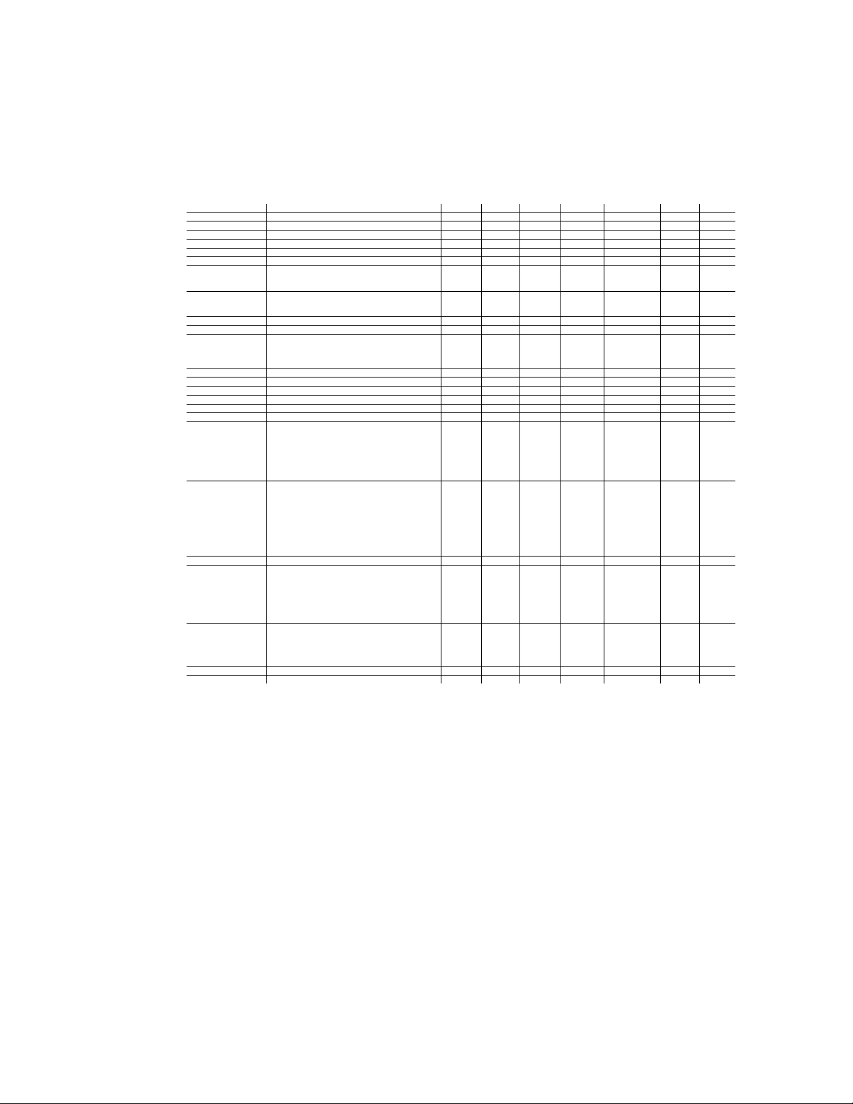
13 Load Cell Color Codes
Manufacturer Models Signal + Signal - Excite + Excite - Shield Sense + Sense -
Advanced Transducers Green White Red Black Bare wire
Allegany Technology Red White Green Black Bare wire
Artech Green White Red Black
Beowulf White Red Green Black
BLH C2P1 C3P1 T2P1 T3P1 White Red Green Black Yellow
Cardinal White Red Green Black Bare wire
Celtron CSB DSR LOC SQBSTC STC-SS DSR CLB HED DLB Green White Red Black Bare wire
Dillon Canister Tension Black Red Green White Orange
Force Measurement Green White Red Black Bare wire
GSE White Green Red Black Bare wire
HBM BLC BLF JRT PWS RSC SBF SB3 USB U1T Z6 White Red Green Black Yellow
Interface SSM 1200 3200 Green White Red Black Bare wire
Kubota Green Blue Red White Yellow
National White Red Green Black Yellow
NCI White Green Red Black Bare wire
Pennsylvania Green White Orange Blue Bare wire
Phillips Green Grey Red Blue Bare wire
Revere Transducer 62HU 63HU 363 953 9523 Green White Red Black Bare wire
Rice Lake RL20000 RL20000SS RL20001 RL20001HE RL30000
Sensotec White Green Red Black Bare wire
Sensortronics 60001 60008 60018 60030 60036 60040 60048 60048SS
Tedea Huntleigh 4158 Green White Red Black Bare wire
Toledo White Red Green Black Yellow
Weigh-Tronics White Red Green Black White/Orange
LPS Green White Red Blue Barewire
HOC MOC Red White Green Black Bare wire
Compression Black Red White Green Orange
Z-cell White Green Red Black Orange
BBS White Red Green Black Bare
PLC B35 Green White Red Black Yellow
SP4 White Red Green Black Yellow Orange Blue
92CC 93CC 42U 43U 263D 462 5102 5103 5123 5223
5723 6762 9102 9103 9123 9363
392B 642 652 692B2 BSP HPS USP1 White Red Green Black Bare wire
792 933 SHB SSB White Red Green Black Clear
CP1 CSP1 White Red Green Black Orange
RLC Brown White Pink Grey Bare wire
RL35023 RL35023S RL35082 RL35082S RL35083
RL39123 RL39523 RL50210 RL65044 RL70000
RL75016 RL75016SS RL75040A RL75058 RL75060
RL75223 RL90000 RLETB RLETS RLHSS RLMK4
RL50500 RL70000SS RL71000HE RL75016HE
RLMK15 RLMK21 RL75061
RLMK1 White Green Red Black Orange Yellow Blue
RL1521 Green White Red Blue Bare wire
60050 60051 60060 60060-0101 60063 65007 65016
65016SS 65016W 65023 65023S 65023SS 65024
65040A 65040S 65058 65058S 65061A 65083 65083S
65114
60007 60064 White Red Green Black Bare wire
65088-1000 65088-1114 White Red Green Black Orange
3411 3421 Green White Red Black Bare wire Blue Brown
240 1010 1022 1040 1042 1140 1250 1260 1320 9010
605 1030 1240 1241
355 620 3510 White Red Blue Black Bare wire Green Grey
Green White Red Black Orange
Green White Red Black Bare wire
Green White Red Black Bare wire
Red White Green Black Bare wire Blue Brown
21
Page 22

WeighTech, Inc.
1649 Country Elite Drive
Waldron, AR 72958
Toll free: (800)-457-3720
Phone: (479)-637-4182
Fax: (479)-637-4183
Email: [email protected]
Web: www.weightechinc.com
$Id: datascale_1.tex,v 1.1.2.26 2011/03/30 14:37:45 newell Exp $
22
 Loading...