

Page 1

GBDA60 User Guide
1. Introduction
This document specifies the ways for simple use to GBDA60 .
2. User interface tables
2.1 Press
Function GSH300 GBDA60 Button
Power On / Off
Pairing Pairing Off
Long-press (2s) PAP until blue
LED flashes
Very-long-press (5s) PAP until
LED flashes blue/red
Initiate
connect
Power Off / On
Note: A Short Press is assumed to be any button press less than or equal to 1 seconds. A
On and no AV
connect
On and in Standby
state
Short-press (1s) PAP
Very-long-press (5s) PAP until
red LED f l ashes
Long Press is assumed to be any button press longer than 2 seconds. See the following
tables for detailed press-functionality descriptions
2.2 LED
GBDA60 State Blue LED Red LED
Power off OFF OFF
Pairing mode Blue LED and Red LED
flash by turns
Pairing successful Flash 3 times OFF
Standby(no audio channel) Flash 1 time every 2s OFF
Active mode (audio
channel open)
Flash 3 times in 500ms,long
off 2s
Standby(Low battery) Flash 1 time every 2s Flash 1 time every 5s
Active mode(Low battery) Flash 3 times in 500ms,long
off 2s
Charging mode Across to the status On until charging is over
Note : Full battery voltage has been set to 3.7V
Low battery voltage has been set to 3.3V
Shutdown voltage has been set to 3.0V
To temporarily return from shutdown point change battery
Red LED and Blue LED
flash by turns
OFF
Flash 1 time every 5s
Page 2
2.3 PIO Assignment
PIO Definition Function
PIO0 REDLED_ENA Blue led control
PIO1 BLUELED_ENA Red led control
PIO3 PAP
Power and pairing button, pairing/connect/
power on/power off
PIO9 POWER_HOLD Power on/off control
3.TRANSMITTER CHARACTERISTICS
The requirements stated in this section are given as power levels at the
antenna connector of the equipment. If the equipment does not have a connector,
a reference antenna with 0 dBi gain is assumed .
Due to difficulty in measurement accuracy in radiated measurements, it is preferred
that systems with an integral antenna provide a temporary antenna conne ct or
during type approval.
If transmitting antennas of directional gain greater than 0 dBi are used, the
applicable paragraphs in ETSI 300 328 and FCC part 15 must be compensated
for.
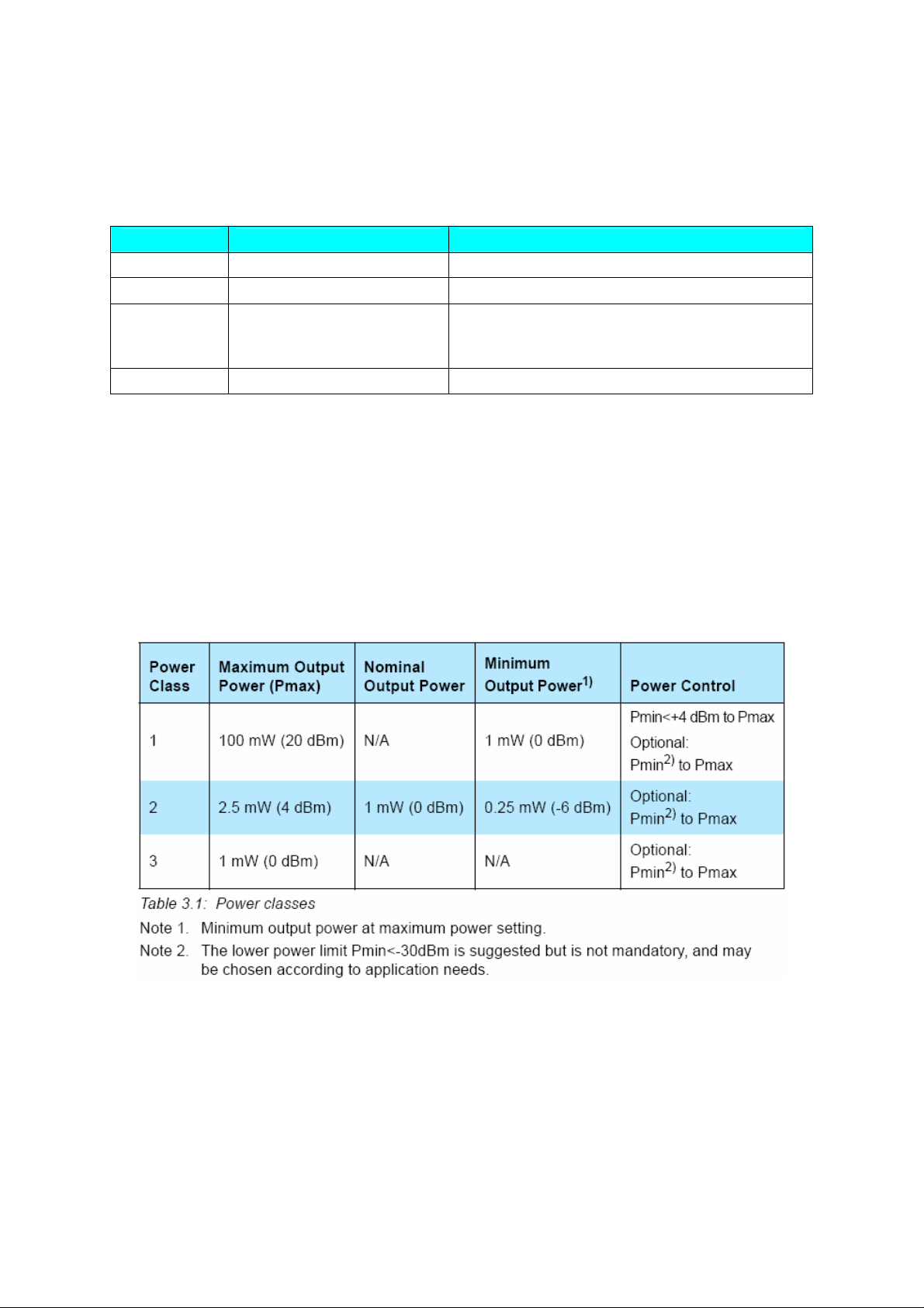
The equipment is classified into three power classes.
A power control is required for power class 1 equipment. The powe r cont ro l is
used for limiting the transmitted power over 0 dBm. Power control capability
under 0 dBm is optional and could be used for optimizing the power consumption
and overall interference level. The power steps shall form a monotonic sequ en ce ,
with a maximum step size of 8 dB and a minimum step size of 2 dB.
A class 1 equipment with a maximum transmit power of +20 dBm must be able
to control its transmit power down to 4 dBm or less.
Page 3

Equipment with power control capability optimizes the output power in a link
with LMP commands . It is done by measuring RSSI and report back if the power
should be increased or decreased.
Note that power class 1 must not be used for sending packets from one device
to another if the receiving side of a connection does not support the necessary
messaging for power control of the sending side (i.e. RSSI mea surem ents and
related messages). In this case, the transmitter should comply with the rules of
a class 2 or class 3 transmitter.
Also note that if a class 1 device is paging or inquiring very close to another
device, the input power could be larger than the requirement in 4.5 Maximum
usable level. This can cause the listening device to fail to respond. It is therefore
useful to page and inquireas well using transmission according to power
class 2 or class 3.
3.1 MODULATION CHARACTERISTICS
The Modulation is GFSK (Gaussian Frequency Shift Keying) with a BT=0.5.
The Modulation index must be between 0.28 and 0.35. A binary one is represented
by a positive frequency deviation, and a binary zero is represented by a
negative frequency deviation. The symbol timing shall be better than ±20 ppm.
For each transmit channel, the minimum frequency deviation (Fmin = the
lesser of {Fmin+, Fmin-}) which corresponds to 1010 sequence shall be no
smaller than ±80% of the frequency deviation (fd) which corresponds to a
00001111 sequence.
In addition, the minimum deviation shall never be smaller than 115 kHz. The
Page 4
data transmitted has a symbol rate of 1 Ms/s.
The zero crossing error is the time difference between the ide al symbol period
and the measured crossing time. This shall be less than ± 1/8 of a symbol
period.
3.2 SPURIOUS EMISSIONS
The spurious emission, in-band and out-of-band, is measured with a frequency
hopping transmitter hopping on a single frequency; this means that the synthesizer
must change frequency between receive slot and transmit slot, but
always returns to the same transmit frequency.
For the USA, FCC parts 15.247, 15.249, 15.205 and 15.209 are applicable
regulations.
For Japan, RCR STD-33 applies and, for Europe, ETSI 300 328.
3.2.1 In-band Spurious Emission
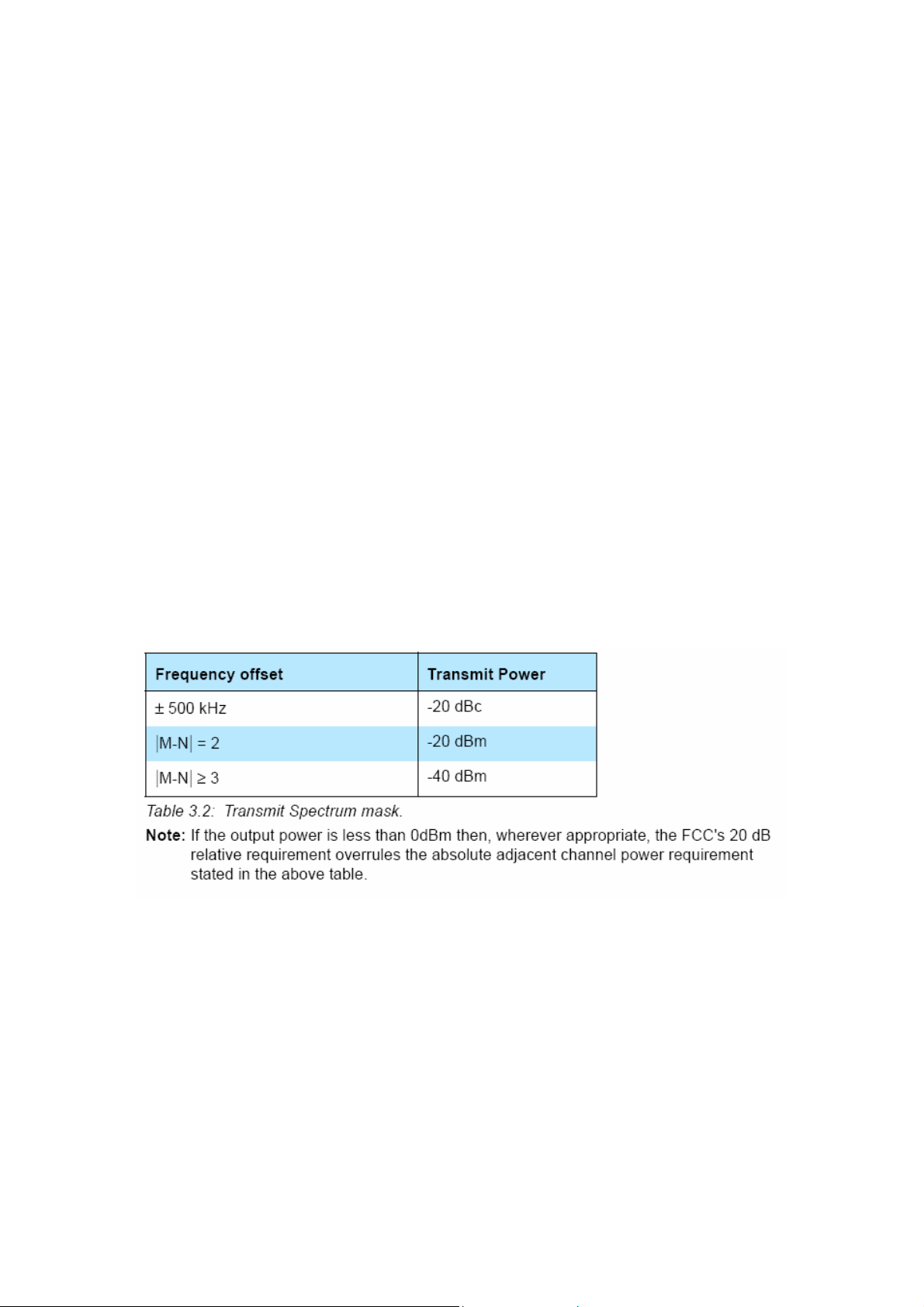
Within the ISM band the transmitter shall pass a spectrum mask, given in
Table 3.2. The spectrum must comply with the FCC's 20-dB bandwidth definit ion
and should be measured accordingly. In addition to the FCC requirement
an adjacent channel power on adjacent channels with a difference in channe l
number of two or greater an adjacent channel power is defined. This adjacent
channel power is defined as the sum of the measured power in a
1 MHz channel. The transmitted power shall be measured in a 100 kHz bandwidth
using maximum hold. The transmitter is transmitting on channel M and
the adjacent channel power is measured on channel number N. The transmitter
is sending a pseudo random data pattern throughout the test.
Exceptions are allowed in up to three bands of 1 MHz width centered on a frequency
which is an integer multiple of 1 MHz. They must, however, comply with
an absolute value of –20 dBm.
3.2.2 Out-of-Band Spurious Emission
The measured power should be measured in a 100 kHz bandwidth.
Page 5

3.3 RADIO FREQUENCY TOLERANCE
The transmitted initial center frequency accuracy must be ±75 kHz from Fc.
The initial frequency accuracy is defined as being the frequ ency ac cur acy
before any information is transmitted. Note that the frequency drift requirement
is not included in the ±75 kHz.
The transmitter center frequency drift in a packet is specified in Table 3.4. The
different packets are defined in the Baseband Specifi cat ion.
Page 6

Federal Communications Commission (FCC) Statement
15.21
You are cautioned that changes or modifications not expressly approved by the part responsible for
compliance could void the user’s authority to operate the equipment.
15.105(b)
This equipment has been tested and found to comply with the limits for a Class B digital device,
pursuant to part 15 of the FCC rules. These limits are designed to provide reasonable protection
against harmful interference in a residential installation. This equipment generates, uses and can
radiate radio frequency energy and, if not installed and used in accordance with the instructions,
may cause harmful interference to radio communications. However, there is no guarantee that
interference will not occur in a particular installation. If this equipment does cause harmful
interference to radio or television reception, which can be determined by turning the equipment off
and on, the user is encouraged to try to correct the interference by one or more of the following
measures:
-Reorient or relocate the receiving antenna.
-Increase the separation between the equipment and receiver.
-Connect the equipment into an outlet on a circuit different from that to which the receiver is
connected.
-Consult the dealer or an experienced radio/TV technician for help.
Operation is subject to the following two conditions:
1) this device may not cause interference and
2) this device must accept any interference, including interference that may cause undesired
operation of the device.
FCC RF Radiation Exposure Statement:
This equipment complies with FCC radiation exposure limits set forth for an uncontrolled
environment. End users must follow the specific operating instructions for satisfying RF exposure
compliance. This transmitter must not be co-located or operating in conjunction with any other
antenna or transmitter.
 Loading...