


OPERATING MANUAL
SPARE PART LIST
W aschbär SE 1 12 / 1 18
HWY1 18 EXT
Weidner Reinigungssysteme
D-74523 Schwäbisch Hall, Steinbeisweg 29
Telefon (0791) 95012-0 Fax (0791) 54 742
e-mail:info@weidner-cleaning.com
Internet: www .weidner-cleaning.com

GeneralRemarks:
1. the "Guidelines for LiquidJets" (RFL) ofthe CentralFederation ofIndustrial Trade Unions
-Technical Committee on Chemistry are to be observed. The brochure "Guidelines
forLiquidJets" is available from the Carl Heymanns- Verlag KG, Luxemburger Straße
449,50939 Cologne, under order No. ZHl/406.
2. The RFL orders that high-pressure cleaning equipment must be tested for operational
safe as often as required, though at least every 12 months by a qualified person
(persons who have adequate knowledge of the pertinent regulations on account of
theirtraining and experience to be able to assess thesafeworkingcondition
oftheequipment). Theresultsofsuch tests are to be puton written record.
3. The owner of the equipment must issue corresponding instructions necessary for a
safe operation and monitor their observance. It is thus necessary that the owner of the
equipment observes the Guidelines for Liquid Jets.
4. If connectedinto the public waternetwork the regulations of the waterworks are to be
observed.
5. When making the electrical connections, pleas pay attention tho the regulations of the
pertinent electric company ( electricity works ).
6. The heating device consists of a bumerwhich must be checked once a year by your
local chimney sweep in accordance with the 1
st
Implementing Order oft the Federal
Pollution Protection Legislation to ensure that the immission limit values are observed.
7. When operatingthe equipmentin rooms, a safe discharge ofthe flue gases must
beensured (flue gas pipe with airflue interruption/ chirnney). Care must also be taken to
ensure that adequate ventilationis provided ( combustion air).
8. Repairs to the high-pressure cleaner may only be carried out by the firm of Weidner or
by a person authorised by such.
9. During repairwork only original Weidner parts may be used in accordance with the
enclosed parts list.
10. 0nly original high-pressure hoses, type DN 8 ST1, operating pressure 210 bar, are to be
used. Please pay particulare attentione to the hoses. Every-pressure hose must comply
with the safety regulations and be marked with the operating pressure, date of
manufacture regulations and be marked with the operating pressure, date of
manufacture and manufacture.
Attention:
High~pressure hoses with a short service life and repaired high-pressure hoses are
extremely dangerous. Burst or leaky high-pressure hoses can lead to injuries, in
particular scaldings through pressurizedhot water.
11. 0nly use chemicals which comply with the detergents act, are biologically degradable
and do not burden the environment. Askfor aDIN specification sheet.
12. We recommend the conclusion of a maintenance contract with the firm of Weidner
agencies to ensure the regular and professional testing of the high-pressure cleaner.

13. Accessories and cleaning agents can be found in our list of accessories. We will be
delighted to help you in the choice accessories and cleaning agents suitable for your
cleaning needs.
14. Befor working on the high-pressure cleaner it must be disconnected from the mains,
remove plug from socket.

Description and function ofthe safety devices
Unloader valve with switch:
The unloader valve limits the operating presur. The desired operating pressure can be infinitely varied with this. If
the max. permissible operating pressure is exceeded or the spray gun closed the unloader valve channels the
water through its bypass line depressurized back to the high-pressure pump.
While the gun is closed the integrated micro-switch will open. About 20 sec. After the mikro-switch opened, the
motor of devices with time delay stop will be cut of.
If thepressure sinks below 10bar , the motor switches on irnmediately again.
*There will be no time delayed stop after the gun closed at devices without time delay stop. The device r uns
without pressure in the bypass. /
Attention:
The unloader valve has to be adjusted that overpressure is not more than 10% over working pressure.
Use and description of the equipment
The Weidner Waschbär SE 112/118 is a fully enclosed mobile hot -water high-pressure cleaning device.
The working pressure is generated by a Triplex pump with 3 ceramic plungers. The pump is flange- mounted
directly on thequill motor. There is apressure regulator with mechanical switch, flow controller and presure relief
valve on the high-pressure side of the pump. When the gun ist closed the pressur e regulator receives a switching
surge which causes the water conveyed by the high-pressure pump to be retumed to the high-pressure pump' s
suction side depressurized. The motor and pump run without a load. Heating is by means of af low heaterwith
heating spiral. The oil feed is controlled by thecontrol chain thermostat, flow controller and microswitch in the
mechanical pressure regulator. Ap-type heating oil switch can be incorporated in this control chain as an
accessory.
If workis interruptedfor longer than 1 minutes the device should be switched offto saveenergy .The device is
suitable to remove dirt from surfaces by means of a freely-expelled water jet. The cleaning device is particularly
suitable forcleaning machines, building facades, stables and floors as well as vehicles such as cars and trucks.
The choice of working pressure depends on the cleaning task. In the case of hard and stubborn dirt the highest
possible pressure should be used for cleaning. The operating pressure depends on the size of t he spray nozzle,
whereby the max. operating pressure is limited by the pressure regulator.
Apart from the working pressure and working distance from the object to be cleaned , thejet shape is also
important for the cleaning effect. A round spray nozzle with an angle of O degrees has the highest mechanical
effect an is, e.g. appropriate for cleaning stables or heavily soiled construction machinery and equipment. Normal
work can be carried out with a 25 degree nozzle. In case oflarge-scale cleaning work, e.g. floors, a 40 degree
nozzle can be used.
Important notices
If you discover transportation damage during unpacking pleas contact your Weidner sales office.
Start-up:
Open the stainless steel cover ( 64), check the oil level in the high-pressure pump and top up as required (see
specifications). /
Electrical connections
The voltage shown on the ratings plate must correspond with the voltage from the source of electr ic power.
The current lead must be fused with 32A on the SE112 ans with 50A on the SE118. A higher fusing is
not allowed.An FI safety switch is to be provided by the customer. .
The electrical connections and mains fusing should ony be installed by a professional.
The device may only be connected to a socket which has been installed in accordance with local laws . Work on
electrical components in the device may only be carried out by a qualied electrican.

Additional safety measures and precautions when working with el
1. Only connect the equipment to regular sources of electric power.
2. Check the cables for darnage before use -never connect damaged cables.
3. Connections must be dry and should not lie on the tl oor .
4. Do not touch the plug with wethands.
5. If an extension cable is used this should be completelyunwound from its drum and should have an adequate
wire cross section, otherwise the cable can overheat (scorch) andcause ashort-circuit;
(Threephase current equipment up to 10 meters long wire cross section 1.5 mm, up to 30 m long 2.5 mm, singlephase device type Waschbär SE 112/118. ..generally at least 2.5 mm wire cross section.)
Water supply
Connect water hose with Geka coupling on high-pressure cleaner at .
Connect water connection piece.
Fully open water tap.
Water feed pressure min. 2 bar,.max. 4 bar:A pressure reducing va1ve must be incorpor atedin the feed
line with higher water mains pressures.
Connection ofthe high.pressure hose
Screw one end of the high-pressure hose onto the pressure output nipple on the device. The other end
ofthe high-pressure hose is screwed to the spray gun.
Cleansant feed and supply
An injector will meter out the cleansant. Connect the cleansant hose to the injektor and place the suction
filter into the cleansant. The quantity of cleansant can be adjusted by turning the hand nut at the cleansant-injektor.
If all the prenamed points are fullfilled, activate the cleansant feed while opening the pressure adjusting nozzle at
the end of the jet pipe. The more the pressure adjusting nozzle is opened the more cleansant will be feed and the
other way around.
The function of the injector takes place only in case of*low pressure*. Feeding takes place only to a max. hose
length of 15 meters. Before using for other purposes consult with the firm of weidner or one of their agencies first.
Protection against freezing
Freeze can destroy equipment which has not been completely emptied of water .The best protection against freeze
is to place the device in a room protected against frost.
Warnings
Do not point the water jet at persons or animals (risk of injuries through pressure and heat as well as irritation of
mucous membranes and acid burn through chemicals ).
Do not point the water jet at the device itself or other electrical components (risk of short-circuits and other
damage ).
The device may not be used in rooms exposed to the risk of explosions.
When using chemicals suitable safety equipment should be worn ( safety goggles, safety overall, safety gloves,
boots etc.).
PIease pay attention to Section " A " of the appendix to VBG 1 35-47, Protection against dangerous chernicals.

Operation
Cold-water operatibn
Appliance switch to "0".
Thermostat to "0" degrees C (off).
Insert appliance plug into socket.
Turn on water supply .
Pull spray gun trigger and set appliance switch to position 1 "pump on".
The device starts.
The pump at first empties the device of air. After a while water comes out of the spray gun. Hold the spray gun
open unntil a steady jet of water is ejected. Now close the spray gun and switch off device.
Screw the lance with nozzle piece (34) onto the spray gun.
The device is now ready for operation.
Attention:
The water jet emitted causes a repulsion power in he spray gun. In the case of an angular lance with a spray
nozzle size 05 the repulsion power amounts to43 N (Newton).
Keep a tight hold on the lance and spray gun.
Cleansant additive
The dilution of the cleansant and the adjustment of the concentration at the metering valve depends on the
cleansant and the field of application.
Cleansant from integrated cleansant tank -turn the switch into the direction "tank".
Cleangant from seperate drum -turn the gwitch into the direction "2" .
If the cleangant tank/ drum is empty the metering valve should be closed (pos since otherwise air will be sucked in
and the working pressure will drop completely. On completion of work with cleansant the device should be
thoroughly rinsed with clear water .
Stopping
Close gun.
Set selector switch to "0".
Close water tap.
Open gun to allow remaining air to escape.
Close gun and secure trigger .
Remove plug from socket
Store hoses without bending ,
Care and maintenance
The care and maintenance of the device are the concern of the oper ator.
This must be carried out carefully so as to maintain the operational safety and efficiency of the device.
Attention:
The most important components of the high-pressure clianer suche as the high-pressure hoses, spray gun, pum p
and safety devices are to be checked for proper function before every use.
Maintenance plan:
Weekly oil level: is the oil cloudly or has it dropped to below the MIN mark ? Change or top up oil.
Oi lchange every 5O working hours at the latest, thoug at the latest every 6 months.
Check heating oil filter for dirt and lean as required.
Scheck filling of lime stabilizer, always keep the stabilizer bottle fun.

Fault and remedies
Fault Possible cause Remedy
device does not start no electricity check cables, plugs
socket and fuse
thermoprobe motor deterrnine and remedy
triggered cause of overload
pilot fuse defect replace pilot fuse
find out cause if there
is a burn throuh again
pump under pressure trigger spray gun
water leak packing worn or plunger pipe defect replace
pump does not reach pressure or water supply inadequate open wat er tap
is loud, pressure fluctations check float valve
clean water inlet sieve
reduce height of suction
suction valve clogged rins pump with clear water
soiled or wom valves, packing worn clean or replace
unloader valve leaky or soiled
nozzle washed out or replace
wrong nozzle size
oil leak on crankshaft shaft seal faulty replace seal, scheck shaft
incrased noise with no loss baring worn out replace bearing,
of pressure change
interval to long
pump oil milky white condensation water forrnation reduce oil change
interval
unloader valve tops at short gun or hp-hose leaky seal, replace
intervals with gun closed jack valve or unloader valve worn out replace jach valve
hight pressure gauge defection when unloader valve incorrectly set or foul adjust unloader valve,
gun closed replace
Water volu me to small wrong no zzle size
use nozzle acc. to rating, plates
nozzle dirty clean or replace
unloader valve too low set sorrectly
unloader valve faulty replace
Chemicals are not sucked in chemical tank emty fill

Chemical line blocked clean
Chemical line faulty replace
injector blocked clean
injector faulty replace
pressure adjustment nozzle too far open
closed
hp-hose too long use a hose w. nominal diameter
20


Pos. No. Bezeichnung Description
2 3851502700 1 Passfeder parallel key
5 3851502745 8 Schraube screw
8 EPACA43344 halb Lagerdeckel quill
10 EPACA43343 2 O-Ring Lagerdeckel o-ring quill
11 EPACA43222 halb Simmering simmering
15 EPACA014480 2 Lager camp
20 EPACA043345 3 Pleuel, kompl. piston rod
25 EPACA044923 1 Kurbelwelle crankshaft
30 EPACA044949 1 Hauptschalter für Bodenbefestigunng main switch for soil attachment
32 EPACA043211 1
Verschluß
(Öleinfüllstutzen
)
catch
33 EPACA014177 1 O-Ring Verschluß o-ring catch
37 EPACA043987 1 Ölschauglas
38 EPACA044428 1 Flachdichtung gasket
40 EPACA092520 4 Schraube screw
48 EPACA025625 1 Ölablaßschraube oil drain plug
49 EPACA023170 1 O-Ring, Ablaßschraube o-ring,
50 EPACA043339 1 Gehäusedeckel discharge screw
51 EPACA043340 1 O-Ring, Gehäusedeckel o-ring, fram cover
53 EPACA043338 1 Kurbelgehäuse crank case
56 EPACA043355 1 Ölwanne oil pan
64 EPACA043351 3 Bolzen pin
65 EPACA43365 3 Plungerstange plunger seaweeds
70 EPACA043228 3 Simmerring Buna-N simmering
75 3851502778 3 Stauscheibe pilot disk
88 EPACA045697 3 Scheibe disk
90 EPACA043367 3 Keramikplunger creamics plunger
96 EPACA043235 3 Stützring, Plungerhalter back-up ring
97 EPACA017399 3 O-Ring, Plungerhalter o-ring, plunger owner
98 EPACA045891 3 Scheibe disk
99 EPACA104360 3 Plungerhalter plunger owner
100 EPACA0456812 3 Dichtungshalter kmpl. seal owner
101 EPACA043302 3 Ölfilz oil felt
106 EPACA043305 3 ND-Dichtung ND-seal
120 EPACA045679 3 Dichtungsgehäuse seal housing
121 EPACA014200 3 O-Ring, Dichtungsgehäuse.Buna-N o-ring, seal housing
121A EPACA011719 3 O-Ring, Dichtungsgehäuse, Viton o-ring, seal housing
125 EPACA046667 3 HD-Dichtung, Buna-N HD-seal
125A 3851502811 3 HD-Dichtung, Viton HD-seal
139 EPACA022179 1 Stopfen, Einlaß 1/2" plug inlet
162 EPACA043357 6 Stützring back up ring
163 EPACA043358 6 O-Ring, Ventilsitz Buna-N o-ring, valve seat
163A EPACA044938 6 O-Ring, Ventilsitz Viton o-ring, valve seat
164 EPACA030821 6 Ventilsitz valve seat
166 EPACA030821 6 Ventil valve
167 3851502832 6 Ventilfeder vale spring
168 EPACA044565 6 Federhalter Ventil penholder valve
172 EPACA017615 6 O-Ring Ventilst. Buna-N o-ring valve Buna-N
172A EPACA015855 6 O-Ring Viton o-ring Viton
174 EPACA043849 6 Ventilstopfen valve pot
185 EPACA044837 1 Pumpenkopf pumping head
186 EPACA012503 2 Federring lock washer
188 EPACA087931 2 Schraube M10x35 screw M10x35
250 803118672 1 Wellenschutzkappe waving protective cap
299 EPACA810027 1 Pumpenkopf komplett pump head cmpl.
350 EPACA030696 1
Werkzeug
(Ventilsitz)
tool (valve seat)
351 EPACA035104 1
Werkzeug
(Dichtungsgehäuse)
tool (seal housing)
300* EPACA033623 1
Dichtungssatz STG,
enthält Nr.97; 101; 106; 121; 125
gasket kit

C:\\HWY_HWYSE112/118EXT
Reinigungssysteme
...die sauberste Lösung
HWY 118EXT_Blechteile
Pos. No. Bezeichnung Description
1 ETA200035 Schi ebebügel W a sc hbär ab 0 6/1999 handle, Ve rsion aft er 06/1999
2 ETD130000 Ma nom eters chl auch, 410 lg. 250 bar h.p. hos e f. pressure gauge
3 3882800060 Brennkam m er VA Wasc hbär SE com bust i on cam ber
4 ETB220102 Stec kdeck el P V C Cover
5 359000 01060 Sich erhei ts therm ost at 9 5°C m i t Tauchhül se safety t herm ostat with di ppi ng case
6 EP A CA 003 00 Hoc hdruck pumpe CAT 300 in spezial ausf. HP pum p CA T 300 sp ecial edit i on
7 ETA200600 Laufrad,schwarz , luft berei ft 260x 85 air wheel,bl ack
8 ETA201500 2 Starlockkappe für 20mm A chs e loc k di sc for wheel
9 3651427520 Hauptschalter für Bo denbefest igun ng mai nswitc h
1
9
2
3 4
5
8
7 6

C:\\HWY_HWYSE112/118EXT
Reinigungssysteme
...die sauberste Lösung
Pos. No. Bezeichnung Description
1418 38 82800 060 Brennkammer V A Wasc hb är SE combus tion cham b er
1423 36 56040600 Ei ns chraubhei zk örpe r 403K 600/44/ 3 B G 1 6000W heatin g uni t 6000W
HWY 118EXT_Rückwand
1
2

C:\\HWY_HWYSE112/118EXT
Reinigungssysteme
...die sauberste Lösung
Pos. No. Bezeichnung Description
1 3882 800 040 Rückwand Wasc hbär SE mont agefertig rear panel
2 3882 800060 Brennkam mer VA Wasch bär SE combus tion cham ber
3 3708 500 518 Hochdrucks chlau ch 600m m 2S T 10,e s A G
R
hp hose 600m m 2S T 10, es A GR 3/ 8"
4 ETD130000 Manom eters chl auch, 410 l g . 250 bar h.p. hos e f. pressure gauge
5 3882 800030 Arm at urbl ech Was chbär S E m ontageferti g front panel
6 E TE504 300 E l ek trom ot or 3,0 KW 40 0V , 50Hz, 1420 Elec trom ot or 3,0 KW, 400V , 50Hz , 1420
7 E TA200 035 S c hi e bebügel Wasc hbä r ab 06/ 1999 9 handle, V e rs i on aft er 06/1999
8 3914 900010 Rohrschel le , 22 m m , A l um i n ium , clam p, al u mi n ium
9 EPA CA00300 Hochdruc kpum p e CA T 300 in spezialaus f. HP pu m p CAT 300 sp ecia l e di tion
10 ETA200600 Laufrad,s chwarz , l uftb erei ft 26 0x 8 5 air wheel, bl ack
11 ETA201500 2 St arl ock kappe für 20mm A chs e loc k disc for wheel
12 35900001060 Sicherhei t st herm o s tat 95°C m i t Tauch hül s e S afet y t herm ost at 95 °C with dipp i ng c ase
13 ETB220102 Ste ck d eckel PV C Cover
1
2 3 4 5
13
12
11 10 8
9
7
6
HWY 118EXT_Seitenansicht
C:\\HWY_HWYSE112/118EXT
Reinigungssysteme
...die sauberste Lösung
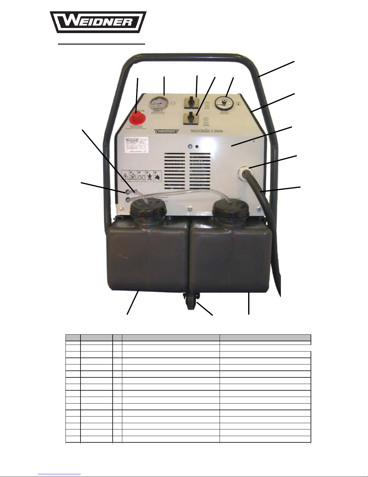
Pos. No. Bezeichnung Description
1 4561 664 xx 8 Kabeltü llen dopps. 9 X 11 X 16 Cable sleeve
2 E TG111055 PV C-S c h l auc h 5 x 2, Länge angeb. PVC hose order leng ht y o u need
3 E TG204500 Dosie rventil für Reini gung s m i t tel dosi ng valve for 2 det ergent
4 ETD260200 1 Druckma nom e ter 0-250 bar, 63mm pressure gauge 0 -250 bar
5 3652 827 502 Ei n-Aus schalter 1 pol i g f. Frontbefestigu ng swit ch off/on 0 / 1
6 3652 827602 Gruppens chal t er 1pol i g f. Fro nt befes tig ung swi t ch 0/ 1/2/ 3 for Heati n g
7 ETE186200 Temperat urregl er 0 -95°C m it Tauch hül se t em pe rature regula tor with dipping cas e
8 E TA200 035 S c hi e bebügel Wasc hbä r ab 06/ 1999 9 handle , V ersion aft er 06/1999
9 E TA190 100 1 Kant ensc hutz ,k l . Länge angeben protect i on profil e order le nght y ou need
10 3882800030 Armaturblech Was chbär S E m ontageferti g front pane l
11 3654899108 Kabel verschra ubung M 32 aus P ol y a mi d cable gla nd M 32
12 3655005100 Gummi kabel H07RN-F 5G1 0 rubber wire 5 G 10mm ²
13 ETB110601 Chemiet ank ant hrazit-grau dtergent tank anth raz i t - grey
14 3759900019 Lenkrol l e 10 0 x 30, 4 Loch Fl a nsch jockey whe el 4 h ol e fixing
15 ETB110701 Heizöl tank anthraz i t -gra u fuel tank ant h raz i t - grey
15 14 13
8
9
10
11
12
3 4 5 6 7
2
1
HWY 118EXT_Frontansicht

C:\\HWY_HWYSE112/118EXT
Reinigungssysteme
...die sauberste Lösung
HWY 118EXT_Schwimmerventil
Pos. No. Bezeichnung Desc ription
1305 39 09900 153 1 PVC Kunststoffschwi m mer 65 x 130 pvc ball 65 x 130
1304 39 09900103 1 Schwim m erventi l 3/ 8" 12m m , 170 mm floatvalve 3/ 8" 12mm ,1 70 m m
1
2

C:\\HWY_HWYSE112/118EXT
Reinigungssysteme
...die sauberste Lösung
Pos. No. Bezeichnung Description
1 ETE504300 Elekt romoto r 3,0 K W 400V, 50Hz, 1420 E l e ct rom o tor 3, 0 KW, 4 00V, 50 Hz, 1420
2 56 80301 580 1 Sc hlauc h tüll e, 3/8" AG x 13 m m brass n i pple 3/ 8" x 13 m m
3 37 80000030 2 1/2" S chl auch (Länge angeb en) 1/2" ho s e (order l enght y ou need)
4 ETE180500 Wass e rm an gel schalter f. Waschbär S E l ow water swic h
5 56 84901 208 1 WE-15 x 3/ 8 Wi nkel verschraubung, h.p. fit ting
6 ETD500100 Unloaderventil VB 9 m. Druck schalter unloaderventil VB 9 w. swit ch
7 56849 01 060 1 GE 12-PLR-R3/8 G erade E ins chraubvers. hp fitting
8 ETD161600 1 12 x 3/8" WE RST S onder - Winke l versc h raubung hp fit ting
9 56 80301500 Schlaucht ü ll e 1/2" A G x 6 mm l ow pr. F i t t i ng 1/2" A G x 6 mm
10 5680301350 T-S tück 1/2" Mes s. AG x IG x IG T-pc 1/2"
11 ETA350040 4 Gummi-Metall puffer, 40 x 30 mm 2xM 8 AG rubber el e m e nt
12 ETD345010 1 V erl änge rung, 60m m, 1/2" AG x 1/ 2 " IG M ext e ntion brass 1/2" x 60 m m
13 5680301630 1 1/ 2" V ersc hrau bung,k eg. 1/2" A g.x A G . M ess . union 1/2" m x m brass
14 5680301410 Winkel 90° 1/2" IG x A G M essing ellbow 90° 1/2" m a. x fe.
15 3708500518 Hochdrucksch l auch 600 m m 2S T 10, es A G R 3/8" hp hose 600m m 2S T 10, es A G R 3 / 8 "
16 3686904003 Muffenschi eber 1/2" sl eeve valve
17 5680301490 3 Schl aucht ü l l e ,1/ 2"AG . x 13mm brass ni ppl e 1/2" x 13 mm
18 3882800040 Rückwand Waschbär S E mon tageferti g rear panel
HWY 118EXT_Pumpenaggregat
1 2 3 4 5
6
7
8
9
18
17
16
15 14 13 12 11 10

C:\\HWY_HWYSE112/118EXT
Reinigungssysteme
...die sauberste Lösung
1
2 3 4 5
6
7
8
9
10
11
12
13
14
15
16
17
18
1920
21
HWY 118EXT_Schaltkasten
Pos. No. Bezeichnung Description
1 3652458110 Miniat urrelais MY 4 24VAC miniat ur relais
2 3652473404 S chütz 12A 1S + 1Ö 24V 50/ 60Hz contac t or 12 A
3 3651427520 Haupts chal ter für Bode nbefes ti gun ng m ai nswi t ch
4 E TE116200 1 Zeitrelais rückfallverzögernd Typ 51183 elect ronic ti m er relais delayed
5 3659151425 1 Verdrahtungskanal LK 4 40/25 PV C ins t all at i on t ube
6 3652291002 12 Durchgangsk lem m e terminal bl oc k
7 3652299000 S chut zleiter Kl em m e ground terminal bl ock
8 3652251201 S chutzlei terk l em me US LK G16N earth terminal
9 3652251110 Reihenk l em me UKN16BU terminal block
10 3652251100 Reihenklemme UK N5B U terminal block
11 3652251200 Schut z l ei t erk lem m e USLK G4 earth terminal
12 E TE600000 1 Transformator RST 100 400V / 24 AC transformer
13 3652299100 3 S i cherungshalter fuse holder
14 3652051951 Glasrohrsicherung 5x20 3,15A t r fuse 5 x 20 3, 15 A tr
15 E TE153500 1 Gl as rohrs icherung 5 x 20 1,0 A t r fuse
16 E TE153500 1 Gl as rohrs icherung 5 x 20 1,0 A t r fuse
17 E TE151300 Glasrohrsicherung 5 X 20 0,5A träge fuse 0, 5A
18 3651773209 Motorschutzs chalt er 6-10A circuit break er
19 3651251300 Dreiphasensc hine 1065mm S Z PS B 4N power rail 3 ~
20 3651851010 Leitungssc hut zs chalt er B10 1polig fus e automat B10
21 3651268220 1 K l emm kasten power panal
 Loading...